Submitted:
09 July 2025
Posted:
10 July 2025
You are already at the latest version
Abstract
Reliable real-time and uninterrupted data tele-communication between subsystems in a Cyber Physical System (CPS) is at the core of secure operation of the CPS. Time-delay and Denial-of-Service (DoS) cyberattacks are among CPS cyber threats that could impair normal functioning in the CPS, through intentional latency in the data tele-communication systems by infliction of data congestion, routing issues, parasitic electro-magnetic interference, etc. Load Frequency Control (LFC) in smart grids are among critical CPS controllers where certain time-delays in the transmission of remote system parameters could cause instability and pervasive havocs within seconds, if not detected and contained promptly. This paper considers a general interconnected CPS of heterogenous subsystems where information is randomly delayed from one subsystem to another. The paper circumvents time-delays caused at the tele-communication layer by augmenting a Multi-Agent System (MAS) of cooperative filters that restore random information delays with negligible and controllable time-delays. Consequently, real-time information would be accessible by the subsystem controllers at all times, regardless of the delays inflicted in the tele-communication layer. The LFC problem has been considered as an example of a challenging CPS that is highly vulnerable to time-delay cyberattacks, and the proposed cooperative filters were used to validate the theoretical results through numerical simulations.
Keywords:
cyber physical systems
; cybersecurity
; time-delay cyberattacks
; multi-agent systems
; load frequency control
; cooperative filters
1. Introduction
Cyber-Physical Systems (CPS) are usually networked systems composed of a number of heterogeneous systems characterized by independent system dynamics, coupled through a set of signals that are transmitted to other systems, where information is exchanged between the systems to enable computation of control commands, in order to regulate or track desired outputs in the systems with reference to an overall control objective in the CPS. In cases where large number of interconnecting nodes are involved it is often advantageous to administer exchange of information merely among adjacent neighbours (i.e., distributed control), rather than deploying a central control architecture that communicates with all the individual nodes. This is particularly important in order to ensure security and reliability, since in this case communication signals can be kept covert and contained in a local fashion. The dispersed nature of CPS often requires public tele-communication infrastructures to be employed for information exchange, rather than dedicated (i.e., leased) communication lines (due to cost and operating expenses). This especially poses threat to the CPS in the form of cyberattacks, and may encounter highly unwanted consequences [1,2]. Therefore, the security of the CPS has to be considered and addressed properly in the CPS design phase. A CPS with a distributed control philosophy in which the systems take part in a cooperative control network to achieve a common goal is referred to a Multi-Agent System (MAS), and the systems are referred to as the agents. Specifically, power generating stations in the LFC problem are subsystems (or agents) of the power system (i.e., the CPS) where system states are collected from remote locations and tele-metered to the controllers through a communication system, in order to regulate the frequency of the grid, and exact the desirable amount of electric power to be traded between the power areas.
Cyberattacks are broadly categorized in the literature into deception, and time-delay or DoS attacks [4]. In deception attacks an adversary attempts to maliciously alter the information packets that are transmitted among the agents in order to cause an intended consequence in the CPS, while time-delays and DoS attacks are obstructive means conducted by adversaries to delay or interrupt in the normal flow of information. The authors in [3,4] have considered the cooperative output regulation problem for heterogeneous linear multi-agent systems in the presence of communication constraints. Cooperative output regulation is a generalization of the leader-follower consensus problem in MAS. Load sharing in power systems as explained in [5] can be formulated from a MAS point of view, in which the area power systems are considered as agents, and limited information are exchanged among the agents to achieve a secondary coordinated control in a decentralized fashion. In [6] the authors have presented a distributed secondary control scheme for power allocation and voltage restoration in islanded DC micro-grids employing MAS consensus control techniques. As far as the LFC problem is concerned, the authors in [24] have performed a thorough literature review with respect to the inadequacies in the literature with regard to LFC with time-delays and packet dropouts. According to their studies "existing works have incorporated either DoS cyberattacks, or time-delays in the control loops", where time-delay resiliency methods in the literature either aim at major modifications in the existing communication systems and controllers (such as in [26]), or suggest gain re-adjustments in PLC controllers [24], or complicated LMI equations that require precise knowledge of system models [25,27,28].
2. Contributions
The contribution of this paper is in the transformation of a "time-delayed CPS" (i.e., a system of systems in which certain information are transmitted from one subsystem to another subsystem through tele-communication channels with random and unknown time-delays) into a "delay-resilient" CPS (that is a CPS with negligible and controllable time-delays in all tele-communication channels), and (importantly) without any modification to any of the existing physical systems, nor with any required knowledge of the constituting subsystems. This is particularly important in industrial CPS where state owned and privately owned systems are involved and intertwined, and where the dynamic models of physical systems are unknown to others (either due to security reasons, or due to the nature of the CPS). Certain examples include the LFC problem in a smart grid, where there are privately owned power generating units with certain security constraints, or in Advanced Air Mobility where anonymous aerial vehicles randomly join and disconnect from the air traffic system. In these cases, various system dynamics with unknown characteristics are involved and it is impractical to modify subsystem’s internal controllers (due to certification, privacy, security issues, etc.). Hence, it is fundamental to involve delay-resilient methodologies at the tele-communication system layer, in a way that is independent of the internal dynamics of the physical subsystems. The authors of this paper strongly believe that such solutions are unprecedented state-of-the-art, and not available in the literature as of this date.
3. Related Works
The conditions for "consensusability" in linear homogenous MASs has been presented in [7,8], where output feedback consensus protocols were given and the closed-loop MAS was shown to be achieving asymptotic consensus if the topology had a spanning tree. Output consensus for heterogeneous MAS with Markovian switching network topologies has been discussed in [9] and can be used as the basis for studying MAS under DoS cyberattacks assuming that DoS attacks can be represented as switching topologies. Unfortunately, [9] does not address communication time-delays and instability issues that can be caused due to information reception delays. The authors in [11] have also attempted to solve the output consensus problem in a leader-follower heterogenous MAS under DoS attack. Unfortunately, the solution proposed in [11] can neither be applicable in real-world, since leader’s dynamic is unknown to the follower agents in most scenarios (especially, in a MAS where the leader is randomly switched from time to time, such as in a MAS of UAVs where the leader may have to be switched randomly from one agent to another for the system to be robust against the leader’s internal faults and outages).
The subject of distributed consensus of heterogenous MAS subject to switching topologies and communication time-delays has been a recent research problem in the literature (as in [10]) with a focus on power systems. This article provides a comprehensive solution for stability and control of heterogenous MAS systems considering a switching controller that alters the controller gain based on the knowledge that a time-delay attack has taken place. The authors in [3] have investigated cooperative resilient output regulation problem with time-delay constraints for a specific class of heterogenous MAS with uniform exogenous inputs (following a LTI dynamics with pure imaginary eigenvalues). Unfortunately, the authors have assumed an exogenous signal that has a predetermined dynamics, which violates a fully arbitrary output trajectory condition for the leaders (as we discussed earlier), due to the fact that the followers are assuming a consensus law that is based on some predefined system parameters. The authors in [4] have recently addressed the same subject for a class of CPS systems with non-uniform but bounded communication delays under denial-of-service (DoS) attacks, where a switching resilient control approach is proposed. However, the proposed controller is only functional for DoS attacks (where agents are assumed to understand "missing" information from neighbour agents) but does not address time-delay attacks.
The authors in [12] have studied consensus in a homogenous MAS, where the agents are expected to follow a given reference command under intrinsic and communication time-delays and disturbances. The authors in [13] have considered consensus problem for discrete-time homogenous multi-agent systems over an undirected, fixed network communication graph, focusing on the robustness of consensus with respect to communication delay. The authors in [15,16] have discussed the problem of output synchronization in a multi-agent system subject to time-delays, with linear right-invertible agents that is subject to arbitrary time-delays. The authors in [17] have addressed adaptive consensus tracking for a class of nonlinear multi-agent systems under time varying actuator faults. Several other recent publications have also paid attention to time-delayed nonlinear MAS output regulation using data-driven consensus [18]. The authors in [19] have discussed consensus problem in a discrete-time nonlinear MAS using sliding mode control laws. The authors in [20] have investigated the consensus problem of MAS with time-varying delays subject to switching topologies with less conservative consensus conditions. The authors in [21] have very recently investigated the group consensus problem for heterogeneous MAS with time-delays via pinning control in the frequency domain. For the LFC problem subject to time-delays which nowadays continues as an ongoing and challenging problem in the literature, the authors in [23] have addressed cybersecurity using linear feedback control employing a set of LMIs. The authors in [24] have used a filtered PID controller that is tuned in the LFC using the particle swarm optimization (PSO) algorithm to solve the problem. More recent research works on the same topic include [26]-[28] to name a few.
4. Definitions and Assumptions
Let us consider an interconnected CPS , and its N constituent subsystems , hereinafter referred to as "subsystems". Generally, subsystems in a CPS may (or may) not involve states that are shared with other subsystems.
Definition 1.
We define an "exogenous state" as a shared state between dynamically coupled subsystems whose value is transmitted from one subsystem to another subsystem through a tele-communication channel. On the other hand "endogenous states" are defined as subsystem states when the coupling between the subsystems are removed. Therefore, one may assume that exogenous states are prone to cyberattacks, and endogenous states are immune against cyberattacks.
- Exogenous states are distinct from exogenous signals in a sense that time-delays in exogenous states can cause instability in the systems. The dynamic couplings between the subsystems can be physical (such as in interconnected power systems) or non-physical (such as in automated air traffic systems in advanced air mobility).
Definition 2.
Let denote the state of , and denote the value of after transmission to , and denote the exogenous state vector of that is transmitted from to . In a delayed communication system and , where is a random time-delay of the communication link from . Therefore, represents the full state vector of which is the sum of the endogenous (i.e., ) and exogenous states .
- When the subsystems in a CPS are dynamically coupled, in order to model subsystem dynamics the state of other subsystems involve. One can imagine a very heavy load that is chained and transported by multiple helicopters, or a power system that involves interconnected power areas, which are examples of physically and dynamically coupled subsystems. Autonomous air traffic control in urban air mobility is another example where the coupling between subsystems are non-physical.
Remark 1.
It is generally problematic to model a dynamically coupled CPS in which randomly time-delayed exogenous states are involved, and where the dynamic model of the subsystems are unavailable to other subsystems.
In this article we consider a multi-agent system framework in order to facilitate time-delay recovery in the CPS. Therefore, we consider an undirected graph where is the set of nodes representing N number of subsystems (or agents), as the set of edges (or communication links between the subsystems), and , representing the adjacency matrix. The elements of are defined such that , if , and , if . Let denote the neighbour set of agent i (where, ). The Laplacian matrix , associated to is defined such that,
where is the diagonal in-degree matrix. Generally, a heterogeneous linear subsystem with a time-delay tele-communication system can be defined by the equations,
where denotes the exogenous states of according to Definition 2. Furthermore, denotes the endogenous state vector of , denotes the local control command vector, and denotes a vector of bounded unknown disturbances, and finally denotes the output vector of , where matrices , and have appropriate dimensions. System matrices are such that when there is no time-delay present in the tele-communication system Equation (2) could be represented as,
as later exemplified in Remark 5 (in Section 8).
Definition 3.
Time-delay resiliency in a CPS is defined as a condition where , and for all , where is an arbitrarily small number, where from Definition 2 we had .
Assumption A1.
We assume that the network is a connected network with N agents, where all subsystems are stable when there in no time-delay in the tele-communication channels. In other words, the endogenous states are continuous Lipchitz functions of time, and there exists a small , such that , for an arbitrarily small .
Assumption A2.
Let us assume that constitute a controllable pair, and constitute an observable pair, for all .
Assumption A3.
We assume that a Denial of Service (DoS) attack on agent i from j is equivalent to the condition in a finite duration in time. This is due to the fact that is equivalent to the edge being removed from , implying no communication service from j to i, hence DoS on i from j.
5. The Load Frequency Control (LFC) Example
The LFC example clarifies the definitions raised in the previous section, and explains the complexities behind modelling of a CPS. The literature [5] models the states of a generating station as denoting the fluctuations and variations in the area frequency, the mechanical power of the prime mover, the governor valve position, the integrated Area Control Error (ACE) of the equivalent generating units, where ACE , and the interconnecting tie-line power, respectively, as in Figure 1, where,
where are positive constants, and where is a control variable calculated by the Central Control Station (CCS) and transmitted to as shown in Figure 1. in the figure denotes variations in the power of the area transmission lines and intermittent renewable energies, and is considered as a random variable. The objective of the LFC as the name implies is to control the area frequency with respect to changes in , while maintaining the preset amount of energy exchange between the areas (i.e., ). In other words, the objective of the LFC is that,
This is due to the fact that is often a time-varying contracted variable between two areas and is set by the main input in Figure 1, where one area commits to supply a regulated amount of energy to the other area, irrespective of the variations in area load. and are exogenous states for , and the first three entries of are endogenous states for .
A time-delay cyberattack on the tele-communication channels of causes the actual to be observed by the controller in as , where is an unknown random time-delay. Similarly, let denote the desirable power to be traded between and its adjacent power area . The sensor collecting the instantaneous power is often remote from the controller in . Therefore, the practice is to install Remote Terminal Units (RTUs) inside the power substations (controlling circuit breakers, disconnector switches, and other electric apparatus associated with transmission lines) to continuously read and transmit the value to the CCS through a tele-communication line for the computation of . However, the tele-communication time-delays result in , and being observed in the CCS. Therefore, time-delays affect the computed value , and is further delayed by to finally affect . In the LFC example of Figure 2, ’s are the only exogenous states that are actually required by the generating areas for the operation. However, the CCS requires the tie-line power values (i.e., ’s) and the area frequencies ’s to compute the ’s. Figure 2 depicts the interconnection of the area generating stations in an LFC through power transmission lines and the flow of information, as an example of a CPS.
6. Problem Statement
Before we formally state the problem let us note from the definitions and the assumptions that , resulting , where is a vector of ones. Through substitution in Equation (2) it follows that,
where , and due to the controllability condition in Assumption A2 one would be able to design a feedback control law such as using methods, so that , and for an arbitrarily small , ensuring stability of the CPS in a Lyapunov sense. This would be always possible since could be considered as a small disturbance similar to and rejected through an appropriate state feedback. Therefore,
Remark 2.
A time-delay resilient CPS as in Definition 3 guarantees stability of the CPS under all random time-delays , including the objective in Equation (5).
Let denote a connected graph of a CPS with random communication delays between the constituent subsystems . Let be an endogenous state of to be transmitted to all other subsystems , and let denote the delayed value of at , respectively, where .
The problem is to recover the real-time value of at all recipient subsystems , with an arbitrarily negligible time-delay , by cooperative-filtering of the delayed signals. In particular, the objective is to find an LTI filter with impulse response so that,
for all , where ’s are real constant coefficients, is an arbitrarily small transient time for the filter , and where is the input of the filter, and are auxiliary inputs from the neighbouring subsystems of .
Definition 4.
A CPS that incorporates the exchange of information among constituent subsystems in order to achieve a common goal (i.e., time-delay resiliency) in a distributed system framework is referred to as a Multi Agent System (MAS), and the processing component (e.g., the filter) in each subsystem that involves the exchange of information is referred to as an "agent". Therefore, the cooperative filter proposed in Equation (6) is a MAS.
7. Main Results
The multi-agent filtering structure in Figure 3 guarantees time-delay resiliency in the CPS despite of the random time-delay cyberattacks on the communication channels, and the objective is to attain the real-time value of a state in agent .
The filters are identical in all agents and are located immediately after the data receivers. The internal block diagram of the filter is as shown in the box for where the input can be if there is a direct communication link between , or any arbitrary conjecture available to . The output of the filter is where is a controllable transient time for the filter that can be arbitrarily adjusted through the filter gain , and is fed to the internal controller in and simultaneously shared with the neighbouring agents. The interesting and important characteristic of the multi-agent filtering scheme is that the outputs of all filters will become identical after lapse of the filter transients and within a negligible settling time . In particular, for any arbitrary set of inputs one will have,
regardless of the time delays in the tele-communication channels. Consequently, if any single agent such as temporarily maintains its output at , then it follows that,
which satisfies the objective in Equation (6). This implies that any single agent in the MAS such as where its output follows its input for a time period will act as the leader in the MAS and all other agents in will follow and track the output . More specifically,
Remark 3.
The connected MAS shown in Figure 3 will achieve consensus as in Equation (7) regardless of the time-delays in the tele-communication links, and the consensus value will be equal to the output of the leader only if there is a single leader such as available in the MAS, and where the leader is characterized by the equation .
Remark 4.
Clearly, realization of time-delay resiliency through the cooperative filters does not involve dynamic models of the subsystems (as it is evident from Figure 3). Furthermore, can be arbitrarily reduced to improve the error ϵ in Definition 3 by increasing the filter gain γ (refer to [30] Theorem-2). Finally, cooperative filters are components that can be added to existing communication systems without necessary modifications to the existing subsystems.These characteristics are unique advantages that would make the presented technique an ideal solution for CPS time-delay security.
However, in case there are multiple leaders in the MAS the consensus output will be the centroid of the leaders outputs. In what follows the statement in Remark 3 will be justified mathematically, which constitutes firstly, proof of the stability of the MAS filter scheme in the presence of time-delays, and secondly, the output consensus of the MAS under all random time-delays. The following equations can be derived from the schematics of in Figure 3.
or,
which follows that,
In order to simplify the notations let and . With this simplification, the input/output equation of the MAS in Figure 3 reduces in a compact form to,
where is the diagonal in-degree matrix as defined earlier, , and is the adjacency matrix of the nodes with time delay , where . Note that in case of no time delay, the input-output relation of Figure 3 could be simply represented as , where the laplacian matrix would be .
Lemma 1.
For a connected MAS with no time-delays, the cooperative filter in Figure 3 with a sufficiently large gain ensures that , as , if is not filtered, while all other agents use to filter their inputs as depicted in the figure.
- The proof is straightforward and can be found in standard MAS textbooks. The implication of Lemma 1 is that the schematics in Figure 3 guarantees that the agents filter outputs simultaneously converges to if all the agents except use to filter their inputs, and if the output of is simply connected to the input of , when there is no time-delay in the system. Theorem 1 and Theorem 3 below will prove that this would be the case even if there is a time-delay in the communication channels, and this would prove time-delay resiliency of the MAS in Figure 3. The condition would be equivalent to for an arbitrarily small and a sufficiently large .
Theorem 1.
Proof.
Assume the Lyapunov candidate function,
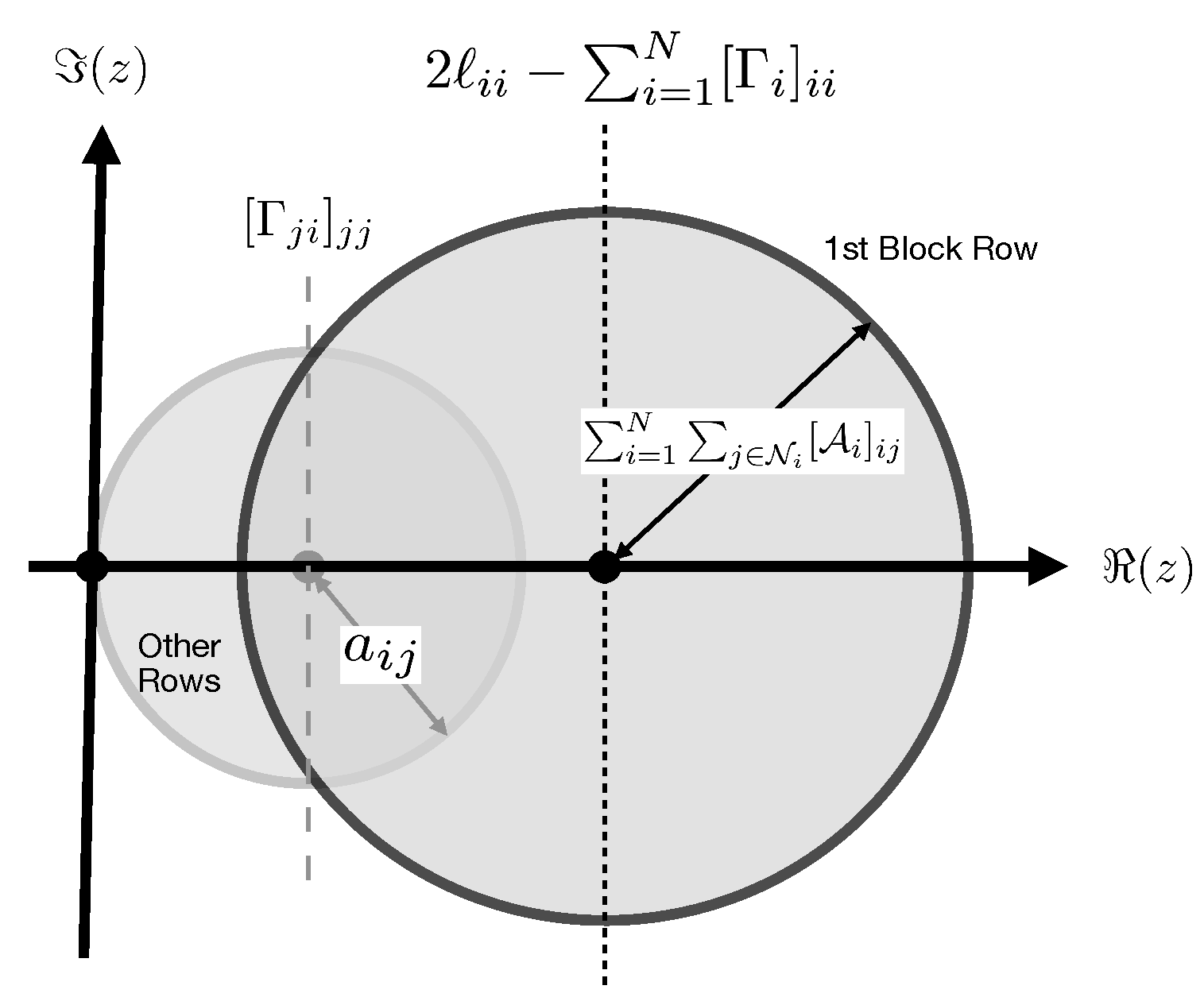
- In order to prove the theorem it would be sufficient to show that , since in this case , or , or , implying boundedness of . However, from Equation (10) it follows that,which can be written in a compact form as,where, , excluding , and , excluding , and , excluding , where is a diagonal matrix with all entries being zeros except . Therefore, one can write,where it is denoted that,and the sufficient condition for marginal stability is to have . We use the Gershgorin disk theorem to evaluate the eigenvalues of , which states that "if is an real matrix, then all the eigenvalues of M are located in the union of the following sets",
- Consequently, the condition is equivalent to satisfying the following conditions simultaneously,or,where the second condition always hold since . On the other hand , where , validating the first condition for all i. In conclusion, for all finite one may assume , which completes the proof of the theorem. □
Figure 4.
Spectrum of with reference to the Gershgorin disk theorem, is the union of several disks where each disk corresponds to a row in . The bigger circle represents the first N rows, referred to as the first block row, where the center of the disk is on the real axis and at to the right, with a radius . The smaller disk represents the set of other block rows where each row is represented by a disk with its center on the real axis at and a radius , and a set of null disks located at the origin.
- Theorem 2 below will examine consensus in a delayed cyber-system that is governed by the control protocol in Theorem 1.
Theorem 2.
The connected MAS with finite time-delays in Theorem 1 achieves consensus. In other words, there exists some , such that , as , where is a column vector with all unit entries.
Proof.
One can prove consensus if at (i.e., the equilibrium), and if equilibrium point is at . Therefore, consensusability would be equivalent to the condition, where firstly, the sum of all the entries in every row of is zero, and secondly, if .
In Theorem 1, it was specified that , and , (with every other entry being zero), and (with every other entry being zero). This implies that and , or , and . On the other hand, since , and , it follows that, , and finally, and , which proves that is an equilibrium for V. On the other hand, since is the only solution for , it follows that is the only equilibrium, which completes the proof of the theorem. □
Theorem 3.
A time-delayed connected MAS with the cooperative filter scheme in Figure 3 is time-delay resilient with respect to against all bounded time-delay attacks, if is the output of . In other words .
We omit the proof of this lemma due to space constraints. However, one can have a non-rigorous proof to this theorem from the implication of Theorem 2, which states that the output of all the agents in Figure 3 at is necessarily equal regardless of their inputs at time t, and since the output of is for all t including , it follows that the output of all the filters at is , which proves the theorem.
As discussed in the Assumptions, a DoS cyberattack from agent i to j can be represented by the assumption . Therefore, a DoS cyberattack on a random set of edges (where represents the attack on some edges) in the time duration would result a random subgraph and a new Laplacian matrix where, .
Theorem 4.
The cooperative filter scheme in Figure 3 achieves asymptotic consensus under arbitrarily random DoS cyberattacks, if there is no infinite DoS attack that disconnects the graph.
Proof.
Let us denote that , and . Let us also denote the Laplacian matrix of the MAS comprising the leader and the followers as . We have seen from Theorem 1 that for a non switching topology and therefore are asymptotically stable for all . However, in case of random DoS attacks (refer to [14]) we assume that there are possible topologies that an adversary may inflict in the network as a result of DoS attack on one or more communication channels, including disconnections in the grid among the followers as well as the leader. Let us consider Laplacian matrices corresponding to each scenario, denoted by where (where implies disconnections in the network). Corresponding to each scenario let us consider a symmetric positive definite matrix with the same dimension (i.e., ), and let us additionally consider a Lyapunov function .
We will further assume that a random switching scenario takes place for where is finite for all . In order to prove Theorem 4 it would be sufficient to prove that for an arbitrary and an arbitrary topology (denoted by and ), one could find a up to the next switching scenario (with topology ) such that . For this, one could simply derive and as,
and,
Substituting in Equation (13), one could obtain,
However, if
or equivalently,
then , or simply , for all , implying that , which further implies that , as , or , as .
This could always be possible even if or , which proves that there always exists positive symmetric matrices for all such that the Lyapunov function uniformly decays for all scenarios , under the condition that a disconnection does not last infinitely, which completes the proof of the theorem. □
8. Simulations and Case Studies
The results derived in Section 7 can be validated by examining the LFC problem discussed in Figure 2, when the CPS is under time-delay attacks and multiple tele-metered variables such as are simultaneously attacked by different random time-delays, and when is a random non-predictable bounded disturbance in the area load. To the best of the knowledge of this authors the above problem is yet a state-of-the-art open problem constituting an open challenge in the literature. The objective is to guarantee that for all bounded load variations , regardless of the time-delay cyberattacks. The time-delayed LFC equation for area can be represented by,
where is the state vector of the endogenous states in , is the vector of the exogenous states in from (i.e., the central control station CCS) as in Figure 1, and where,
and where is a disturbance in the LFC representing the variations in the area load, and the renewable energies that contribute to the area power generation.
Remark 5.
Clearly, in a real-time LFC without time-delays is the state vector for as explained in outset of Section 5, and is the state matrix of the LTI system.
- Refer to the explanations provided prior to Definition 3 for details.
In the simulation results below, a relatively significant and sudden load change in ( of the nominal area load at time and , as per the dashed line Figure 6) that triggers swings in the power system which has to be contained automatically. Time-delay attacks (if present) are capable of inducing severe instability in the power system if not appropriately circumvented as shown by the thinner line in Figure 5, which depicts the variations in the area frequency when resilient filters are not present.
The solid curve in Figure 5 illustrates the simulation results in the presence of cooperative filters (outlined in Figure 3), where all tele-metered signals were conditioned by before they were applied to the agents . Corresponding to each exogenous state variable (i.e., , and ) a cooperative filter is deployed to recover time-delays in the signals. As a result, the instability in the power system can be maintained and the swings in the frequency in result to load variations are rapidly contained.
The thick line in Figure 6 depicts the ACE in response to a load variations (the dashed line). The ACE is the control parameter telemetered by the CCS to all individual power generating units participating in the LFC. In the absence of a resilient filter mechanism, time-delay attacks on tele-communication links cause delayed inputs to CCS and delayed commands transmitted to the generating units.
This inflicts uncontrollable swings in the area power system that disseminates to the entire power system as exemplified in 5. For the purpose of comparison, the time-delayed ACE signal without deploying delay-resilient cooperative filters would be as in Figure 7. It is important to note that the CCS requires to be transmitted from (as explained in Figure 2), as well as to be transmitted from , in order to compute according to Equation (3). Without employment of a time-delay resilient methodology, the delayed information and would cause instability in the CCS controlled which will be disseminated to , which indeed is the phenomenon taking place in our case studies. Clearly, being at it appears to be heuristically impossible to recover the real-time signal from , since the instability observed in stems from a delayed signal transmitted from . Consequently, recovery of (while being at ) requires information that is clearly beyond the reach of . The significance of the proposed methodology in this paper would now become clear, as it has been possible to restore normality in the entire CPS without requirement of subsystem’s information, and only through the filtering of available signals at the subsystems.
Figure 8 depicts the electric signal to the governor servo-valve of the generator in in response to the disturbance in the area load. It is evident that the load change triggers a command to the servo-valve in order to compensate for the load, ensuring complete balance in the supply-demand, which expectedly guarantees that and .
However, satisfactory functioning of the time-delay resilient LFC control scheme proposed in this paper strictly depends on the bandwidth of the tele-communication system and the speed of data transported between the system controllers, in comparison to the natural frequency of the system states. Figure 9 illustrates the importance of the tele-communication system bandwidth by comparing two scenarios. In the first scenario (thick line) a high bandwidth system is deployed, and in another attempt low bandwidth communication channels were being used. It is evident that inadequate bandwidth gives rise to instability in the power system (as depicted by the thin line in Figure 9).
Finally, Figure 10 is a general schematic of a part of an interconnected CPS with a random topology. It is assumed that the subsystems are transmitting equivalent reference signals to others, where each signal is subject to a random time-delay.
Figure 11 is the simulation result of the cooperative filters for five interconnected subsystems in a discrete-time framework. It is evident that the filters can track the real-time reference signal despite of the unknown time-delays within a time-duration .
9. Conclusion
Resiliency against time-delay and DoS cyberattacks on CPS, and in particular, the LFC problem in smart grids have been investigated in this paper. It has been shown that augmentation of the tele-communication receivers with certain cooperative filters that exchange their outputs with neighbouring filters (in a multi-agent system framework) can circumvent time-delay sabotage, without any modification to the systems internal controllers. In essence, the cooperative filters receive the time-delayed outputs of their neighbouring filters and augment this information with a locally derived conjecture of the real-time value of some exogenous state that is under time-delay cyberattack, to derive the true real-time value of the attacked state under question. The paper has also shown that finite-time denial of service (DoS) cyberattacks cannot distract the convergence of the cooperative filters and invalidate the results. Theoretical results of the proposed methodology has been examined through a case study in a simulation platform that involves a load frequency control problem in a multi-area power system. Complicated control problems such as random time-delays in the transportation of data packets in the LFC that normally elevate instability issues and severe frequency swings had been successfully contained through the proposed cooperative filtering scheme as a result of the simulation.
References
- Feng, G. Wen, and G. Hu, Distributed Secure Coordinated Control for Multiagent Systems under Strategic Attacks, IEEE Trans. Cybern., Vol. 47, No. 5, Pages 1273-1284, May 2017. [CrossRef]
- D. R. Ding, Z. D. Wang, D. W. C. Ho, and G. L. Wei, Observer Based Event-Triggering Consensus Control for Multiagent Systems with Lossy Sensors and Cyber-Attacks, IEEE Trans. Cybern., Vol. 47, No. 8, Pages 1936-1947, Aug. 2017. [CrossRef]
- A. Abdessameud, A. Tayebi, Cooperative Output Regulation of Linear Multi-Agent Systems with Communication Constraints, IEEE 55th Conference on Decision and Control (CDC), Las Vegas, USA, December 12-14, 2016.
- C. Deng, C. Wen, MAS Based Distributed Resilient Control for a Class of Cyber-Physical Systems With Communication Delays Under DoS Attacks, IEEE Transactions on Cybernetics, Early Access, March 2020. [CrossRef]
- S. Shahkar, K. Khorasani, A Resilient Control Against Time-Delay Switch and Denial of Service Cyber Attacks on Load Frequency Control of Distributed Power Systems, 4th IEEE Conference on Control Technology and Applications (CCTA 2020), Montréal, Canada, August 24-26, 2020.
- F. Guo, Q. Xu, C. Wen, L. Wang, P. Wang, Distributed Secondary Control for Power Allocation and Voltage Restoration in Islanded DC Micro-grids, IEEE Trans. Sustain. Energy, Vol. 9, No. 4, Pages 1857-1869, Oct. 2018. [CrossRef]
- S. E. Tuna, LQR-Based Coupling Gain for Synchronization of Linear Systems [Online]. Available: http://arxiv.org/abs/0801.3390.
- C. Ma, J. Zhang, Necessary and Sufficient Conditions for Consensusability of Linear Multi-Agent Systems, IEEE Transactions on Automatic Control, Vol. 55, No. 5, May 2010.
- M. Meng, L. Liu, G. Feng, Output Consensus for Heterogeneous Multiagent Systems with Markovian Switching Network Topologies, International Journal of Robust and Nonlinear Control, DOI: 10.1002/rnc.3918, Feb. 2018. [CrossRef]
- M. Meng, G. Xiao, C. Zhai, G. Li, Z. Wang, Distributed Consensus of Heterogeneous Multi-Agent Systems Subject to Switching Topologies and Delays, Journal of the Franklin Institute 357, 6899-6917, 2020. [CrossRef]
- D. Zhang, G. Feng, A New Switched System Approach to Leader-Follower Consensus of Heterogeneous Linear Multiagent Systems With DoS Attack, IEEE Transactions on Systems, Man, and Cybernetics: Systems, February 2019. [CrossRef]
- Z. Ahmed, M.M. Khan, M.A. Saeed, W. Zhang, Consensus Control of Multi-Agent Systems with Input and Communication Delay: A Frequency Domain Perspective, ISA Transactions 101, Pages 69-77, 2020. [CrossRef]
- T. Qi, L. Qiu, J. Chen, Fellow, MAS Consensus and Delay Limits Under Delayed Output Feedback, IEEE Transactions on Automatic Control, Vol. 62, No. 9, Sep. 2017. [CrossRef]
- J. C. Geromel, P. Colaneri, Stability and Stabilization of Continuous-Time Switched Linear Systems, SIAM J. Control Optimization, Vol. 45, No. 5, Pages 1915-1930, 2006. [CrossRef]
- M. Zhanga, A. Saberia, A. A. Stoorvogel, Synchronization in the Presence of Unknown, Nonuniform and Arbitrarily Large Communication Delay, European Journal of Control 38, Pages 63-72, 2017. [CrossRef]
- Z. Liu, D. Nojavanzadeh, A. Saberi, A. A. Stoorvogel, Scale-Free Collaborative Protocol Design for Output Synchronization of Heterogeneous Multi-Agent Systems With Nonuniform Communication Delays, IEEE Transactions on Network Science and Engineering, Vol. 9, No. 4, August 2022. [CrossRef]
- C. Wang, C. Wen, L. Guo, Adaptive Consensus Control for Nonlinear Multiagent Systems With Unknown Control Directions and Time-Varying Actuator Faults, IEEE Transactions on Automatic Control, Vol. 66, No. 9, September 2021. [CrossRef]
- S. Xiong, Z. Hou, L. Fan, Consensus Control of Unknown Nonlinear Discrete-Time Multi-Agent Systems with Nonuniform Time-Delays, IEEE 12th Data Driven Control and Learning Systems Conference, Xiangtan, China, May 12-14, 2023.
- L. Yuan, J. Li, Consensus of Discrete-Time Nonlinear Multiagent Systems Using Sliding Mode Control Based on Optimal Control, IEEE Access, Vol.10, 2022. [CrossRef]
- X. J. Peng, Y. He, Consensus of Multi-Agent Systems With Time-Varying Delays and Switching Topologies Based on Delay-Product-Type Functionals, IEEE Transactions on Cybernetics, Digital Object Identifier, 2022. [CrossRef]
- F. Sun, X. Wu, J. Kurths, W. Zhu, Group Consensus for Heterogeneous Multi-Agent Systems With Time Delays Based on Frequency Domain Approach, IEEE Transactions on Systems, Man, and Cybernetics: Systems, Vol. 53, No. 5, May 2023. [CrossRef]
- L. Solyman, A. Elbadawy, A. Meroth, Single Model Scheme Based Smith Predictor for the Mitigation of the Effects of Network Imperfections in Consensus Control of Multi Agent Systems, 10th International Conference on Control, Decision and Information Technologies (CoDIT), 2024.
- Z. Cheng, D. Yue, S. Hu, X. Xie, C. Huang, Detection-Based Weighted H-Infinity LFC for Multi-Area Power Systems under DoS Attacks, IET Control Theory Applications, Vol. 13, Issue 12, Pages 1909-1919, 2019.
- D.K. Panda, S. Das, S. Townley, Towards a More Renewable Energy Based LFC under Random Packet Transmissions and Delays with Stochastic Generation and Demand, IEEE Transactions on Automation Science and Engineering, http://hdl.handle.net/10871/124292, 2021.
- X. Zhao, Z. Ma, S. Li and S. Zou, Robust LFC of Power Systems With Wind Power Under Packet Losses and Communication Delays, in IEEE Journal on Emerging and Selected Topics in Circuits and Systems, Vol. 12, No. 1, Pages 135-148, March 2022. [CrossRef]
- X. C. Shangguan, C.K. Zhang, Y. Zhao, Resilient Load Frequency Control of Power Systems to Compensate Random Time Delays and Time-Delay Attacks, IEEE Transactions on Industrial Electronics, Vol. 70, No. 5, Pages 5115-5128, May 2023. [CrossRef]
- J. Yang, Q. Zhong, K. Shi, S. Zhong, Distributed Coordination LFC Approach for Interconnected Power Systems Under Detection and Compensation Mechanism Targeting DoS Attacks, IEEE Transactions on Industrial Informatics, Vol. 19, No. 11, Pages 11008-11018, Nov. 2023. [CrossRef]
- Y. Wang, Z. Wang, J. Gan, H. Zhang and R. Wang, Switched Observer-Based Adaptive Event-Triggered Load Frequency Control for Networked Power Systems Under Aperiodic DoS Attacks, IEEE Transactions on Smart Grid, Vol. 14, No. 6, Pages 4816-4826, Nov. 2023. [CrossRef]
- K. Karoui, F.B. Ftima, H.B. Ghezala, A Multi-Agent Framework for Anomalies Detection on Distributed Firewalls Using Data Mining Techniques, In: Cao, L. (eds) Data Mining and Multi-agent Integration, Springer, Boston, MA, 2009. [CrossRef]
- S. Shahkar, Cooperative Localization of Multi-Agent Autonomous Aerial Vehicle (AAV) Networks in Intelligent Transportation Systems, IEEE Open Journal of Intelligent Transportation Systems (OJITS), Digital Object Identifier, 2025. [CrossRef]
Figure 1.
Block diagram of a frequency control mechanism for a generating station contributing the LFC in a multi-area power system. The solid lines are hard-wired measurements/commands that are presumably immune from cyberattacks (as they are confined in ), where the dashed lines represent tele-metered data that are subject to TDS/DoS cyberattacks. Borrowed from [5].
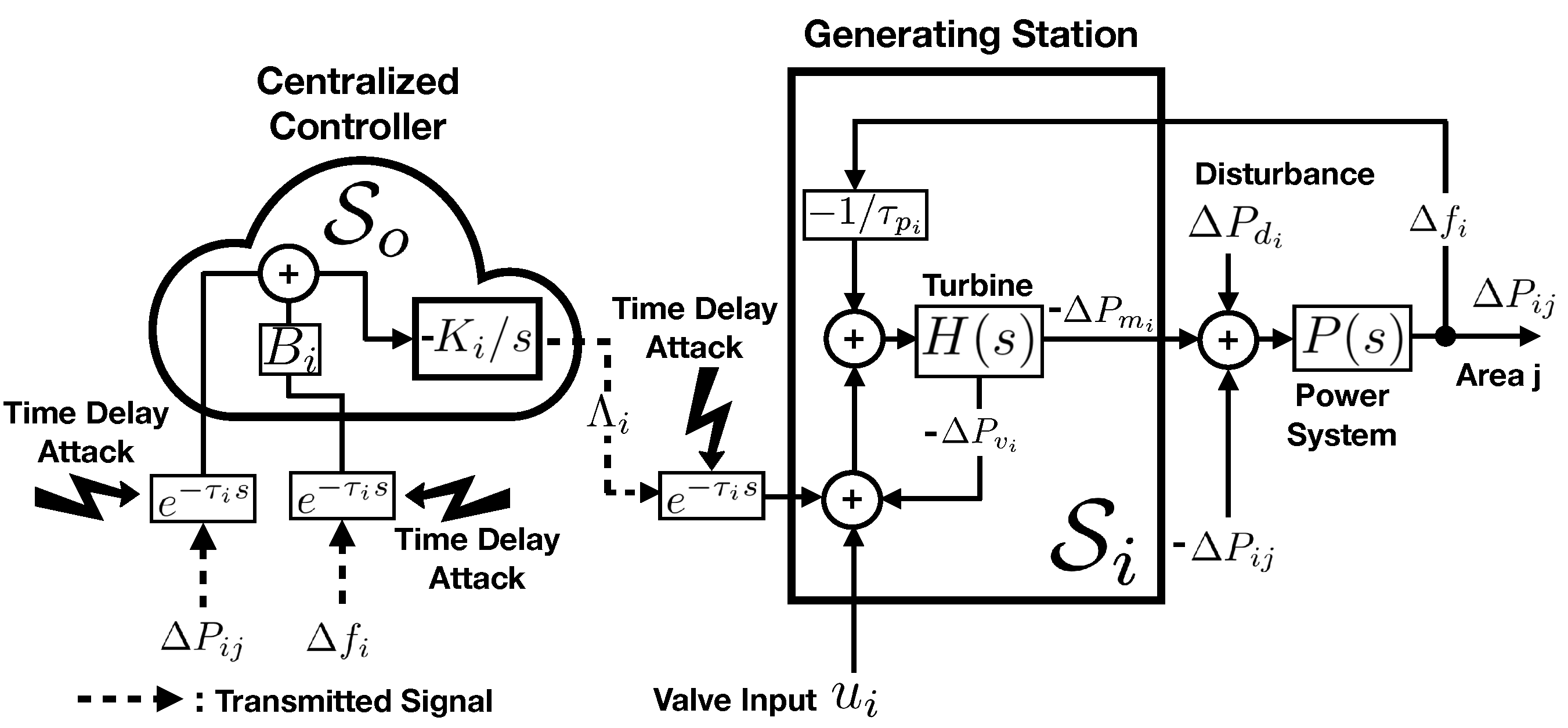
Figure 2.
Schematics of a LFC power system with three area generating stations and the Centralized Control Station . The CPS in this figure can be represented as where denote the two substations, each also considered as a subsystem of the CPS. The tele-communication system can be further regarded as a subsystem in a more comprehensive model. However, this is not considered in this paper. The CCS and the tele-communication system comprise the cyber part of the system that is responsible for the data collection and processing, and the power system comprises the physical part of the CPS. The Front-End Processors (FEPs) are electronic apparatus inside the CCS that transmit/receive tele-communication signals and demodulate the state variables. The Remote Terminal Unit (RTU) is a micro-scale FEP with a similar function located in every substation. is a system state whose sensor (i.e., current and voltage power transformers) is located in a substation, and whose instantaneous value is transmitted to the CCS through an RTU. The CCS receives all , and computes for individual generating stations.
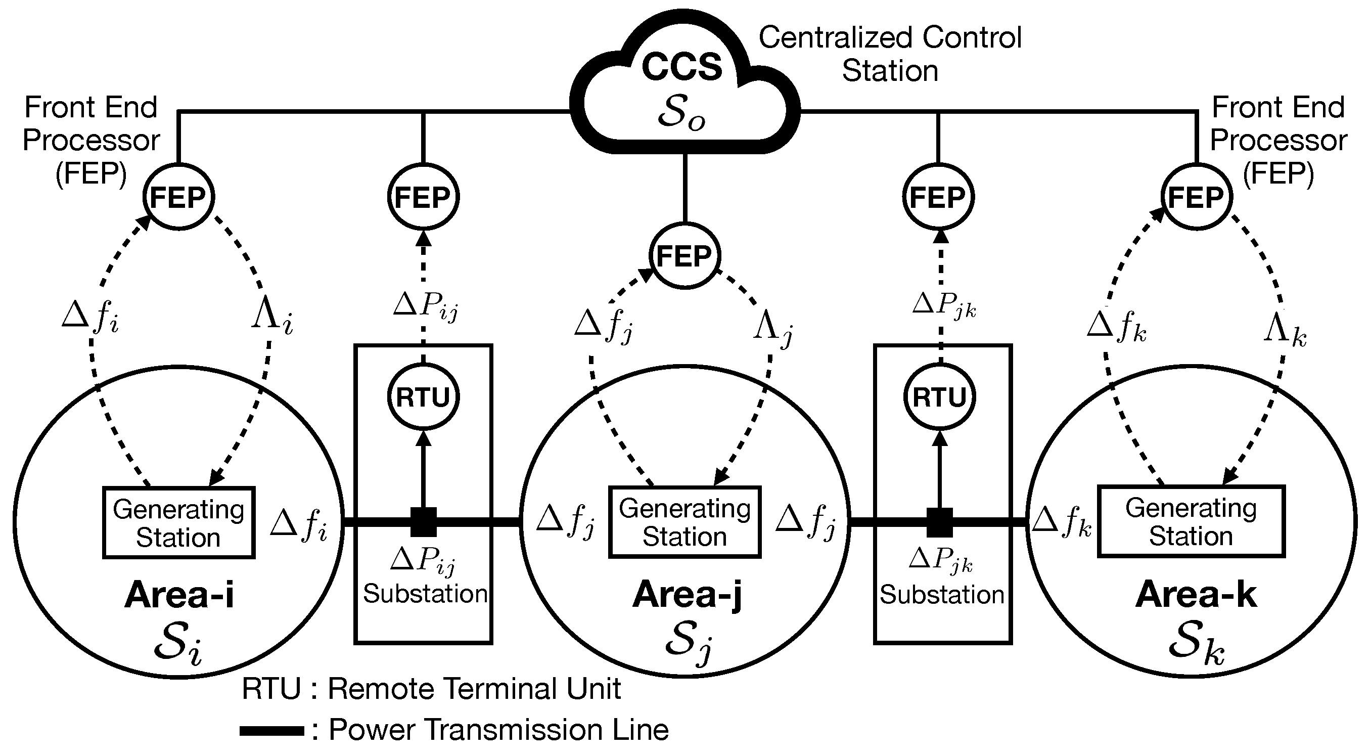
Figure 3.
Schematics of a MAS time-delay resilient CPS, and the schematics of the cooperative filter . The agents in the MAS exchange information in order to recover a time-delayed state . is the input of the filter in (if , or can be any other conjecture available to which needs not be a correct estimate), and the output of the filter is , where is a small response time. It will be shown that , where is a negligible arbitrary settling time for the filter that will be controlled by the filter gain .
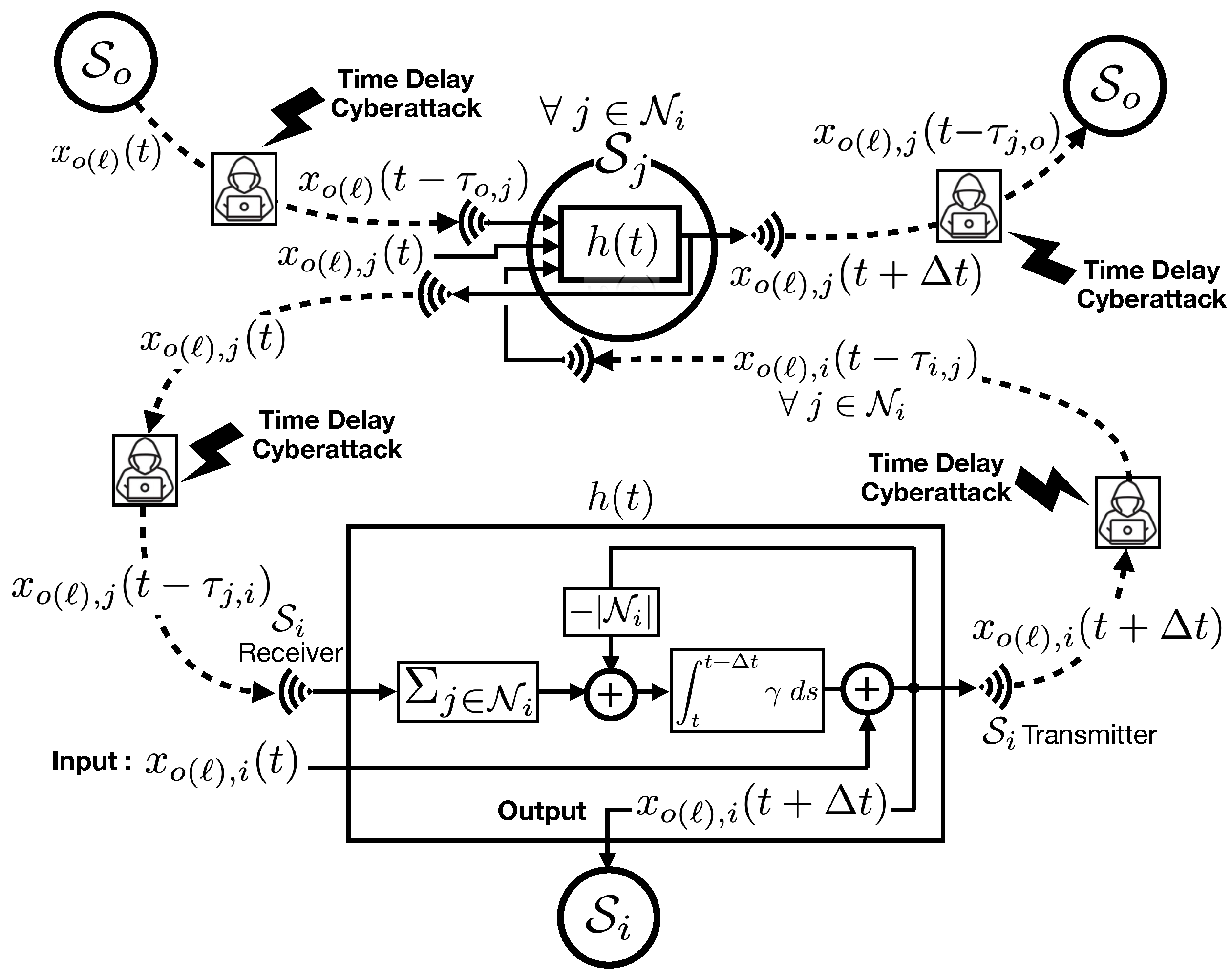
Figure 5.
Performance of the time-delay resilient filter. The thin line represents in response to a load variation in , at and back to 0 at , for the case where a conventional LFC is in operation. Perilous swings in the system frequency are clear when the telemetered data are attacked by sufficiently long time-delays, resulting in pervasive instability in the power system (thinner line). The same scenario is repeated when resilient cooperative filters are deployed (solid thicker line) which demonstrates stability and a satisfactory LFC control.
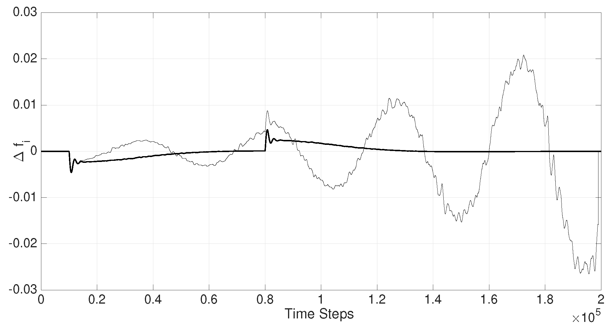
Figure 6.
Variations in as a result of .
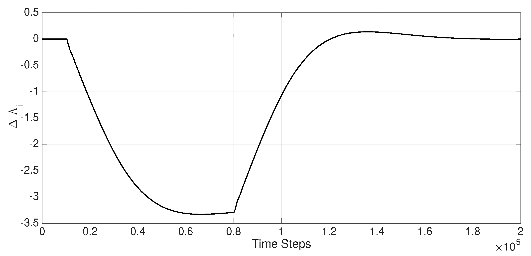
Figure 7.
Time-Delayed ACE signal transmitted from without the employment of a delay-resilient cooperative filter system, and as a result of a 10% load disturbance .
Figure 7.
Time-Delayed ACE signal transmitted from without the employment of a delay-resilient cooperative filter system, and as a result of a 10% load disturbance .
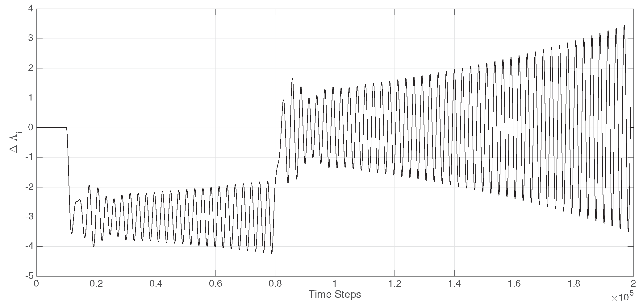
Figure 8.
Adjustment of the servo-valve electric signal in response to the area load variations depicted in Figure 5.
Figure 8.
Adjustment of the servo-valve electric signal in response to the area load variations depicted in Figure 5.
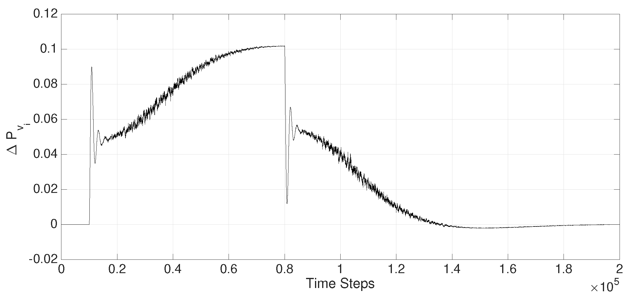
Figure 9.
Affect of the tele-communication bandwidth. Inadequate bandwidth in tele-communication channels result in marginal instability as depicted by the thin line.
Figure 9.
Affect of the tele-communication bandwidth. Inadequate bandwidth in tele-communication channels result in marginal instability as depicted by the thin line.
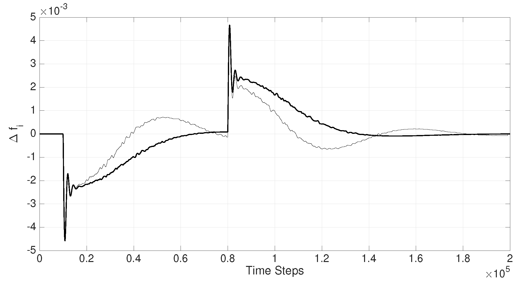
Figure 10.
General architecture of a CPS, subject to adversarial time-delay cyberattacks. The exogenous states of the systems () are transmitted to adjacent subsystems with unknown time-delay and the output of filters in each subsystem transmits the conditioned signal back to the source, hence, cooperative filters. The architecture shown in this figure results in time-delay resiliency in the CPS as demonstrated in Figure 11.
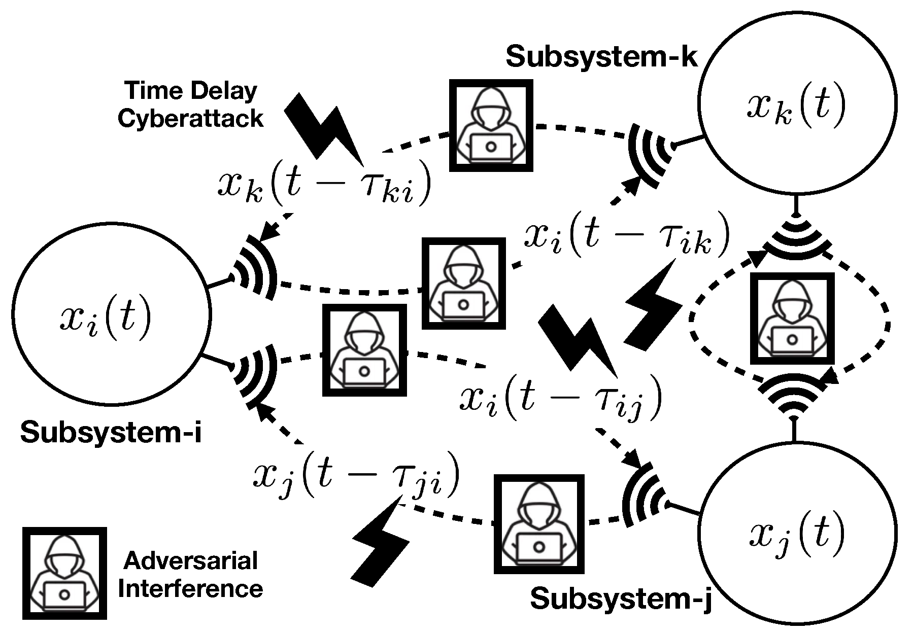
Figure 11.
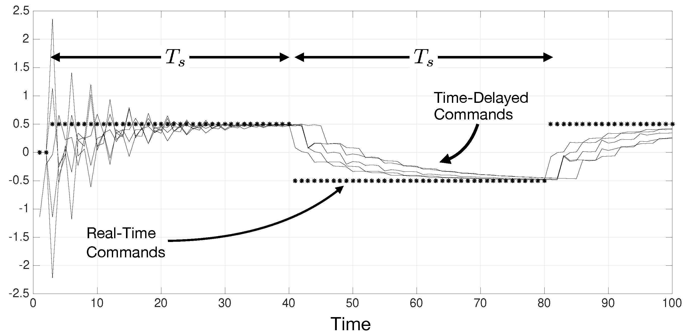
A discrete-time network of five interconnected agents transmitting equivalent reference signals (shown by the asterisks) to adjacent subsystems. The tele-communication channels are randomly delayed and the output of the cooperative filters are shown by thinner lines for each subsystem. It is evident that the delayed signals follow the real-time reference signal in a time-duration that is dependent of the filter gain and the topology of the network.
Figure 11.
A discrete-time network of five interconnected agents transmitting equivalent reference signals (shown by the asterisks) to adjacent subsystems. The tele-communication channels are randomly delayed and the output of the cooperative filters are shown by thinner lines for each subsystem. It is evident that the delayed signals follow the real-time reference signal in a time-duration that is dependent of the filter gain and the topology of the network.
Disclaimer/Publisher’s Note: The statements, opinions and data contained in all publications are solely those of the individual author(s) and contributor(s) and not of MDPI and/or the editor(s). MDPI and/or the editor(s) disclaim responsibility for any injury to people or property resulting from any ideas, methods, instructions or products referred to in the content. |
© 2025 by the authors. Licensee MDPI, Basel, Switzerland. This article is an open access article distributed under the terms and conditions of the Creative Commons Attribution (CC BY) license (http://creativecommons.org/licenses/by/4.0/).
Copyright: This open access article is published under a Creative Commons CC BY 4.0 license, which permit the free download, distribution, and reuse, provided that the author and preprint are cited in any reuse.


