Submitted:
11 July 2025
Posted:
15 July 2025
You are already at the latest version
Abstract
Gate dam and earth–rock dam systems have many advantages, such as minimal ecological impact and good terrain adaptability, making them the preferred dam type for low-head, high-flow river areas with thick overburden layers. This study, based on an ongoing construction project, pioneers a comprehensive three-dimensional stress–deformation characteristic analysis of a gate dam and earth–rock dam system. The results indicate that the spatial non-uniformity of dam deformation is significant, with the earth–rock dam section exhibiting greater deformation than the gate dam section, which is related to the uneven distribution of dam loads and soil layers. Joint displacements in the gate dam section are larger on the two banks, while deformation consistency is better in the central section. In addition, the lack of coordination between the deformation of the cutoff wall and the overlying soil layer results in significant bending stress on the cutoff wall, causing a tensile state in the top of the cutoff wall. Due to the gravitational force of the top earth–rock dam, the underground continuous wall exhibits an uneven settlement deformation pattern. Additionally, the strong constraint effect of the gravity-retaining wall above it leads to the formation of tensile stress zones at the top and bottom of the underground continuous wall within a certain range. This study effectively identifies the mutual influences among the components of the gate dam and earth–rock dam system, obtains the spatial deformation characteristics of the mixed dam structure, accurately locates the weak zones in the dam system, and provides important references for engineering design improvements.
Keywords:
SBFEM
; deep overburden
; gate dam and earth-rock dam system
; refined analysis
1. Introduction
As China’s western hydropower development strategy continues to progress, the requirement for deep overburden foundations at dam sites become unavoidable [1]; in addition, river areas typically feature low-head and high-flow characteristics. Gate dam and earth–rock dam systems offer advantages such as minimal ecological impact, short construction periods, and good terrain adaptability, making them the preferred dam type for such sites. Several key regional projects, including Duobu, Futang, Shawan, and Yingliangbao, have been carried out, playing an important and positive role in regional power generation, irrigation, ecological protection, and navigation. However, there is limited research on the three-dimensional deformation characteristics of an entire gate dam and earth–rock dam system, making it difficult to accurately assess and quantitatively evaluate the safety status of these structures during construction and operation. Therefore, studying the deformation characteristics of the hybrid dam system and exploring the mechanisms of deformation interaction between structures is of great significance for dam management decision-making.
To this end, relevant scholars have conducted a series of studies targeting different engineering issues. For example, Wei Kuangmin et al. [2] introduced the settlement control method of gate dam foundation on the complex thick overburden, and a simplified method for simulating large-scale pile groups were proposed. Kong Ke et al. [3] used the Tongzilin Hydropower Station as a case study to investigate the influence of the joint form at the end of the frame-type underground continuous wall on its stress deformation. Jiang Yunlong et al. [4] investigated the stress–strain characteristics of the dam section at Dagu Tan. Wang Dengyin et al. [5] used a three-dimensional finite element model to analyze the static stress–strain characteristics of the dam at Danba. Wu Mengxi et al. [6] successfully simulated the seepage and deformation of spillway dams throughout their entire construction and operational lifecycle. Ren Wei et al. [7] addressed the key issues in settlement control for the Duobu Dam, proposing reasonable standards for uneven settlement, settlement control, and differentiated foundation treatment technologies. Overall, the aforementioned research findings provide important reference value for accurately understanding the deformation characteristics of weir dams. However, due to the limitations of conventional modeling and analysis methods in precision analysis [8], it is challenging to simultaneously consider important components such as earth–rock dams, gravity-retaining walls, spillway weir dams, cutoff walls, underground continuous walls, and unevenly distributed overburden layers within a hydropower plant hub. Therefore, the aforementioned studies primarily focused on local structural analysis and simplified models, specifically on the mechanical response of isolated components, which makes it difficult to reasonably identify the deformation interactions between components within the system.
Given this, this research uses an ongoing mixed dam project as its basis and employs self-developed refined modeling and analysis methods to conduct a three-dimensional deformation characteristic study of a gate dam and earth–rock dam system, exploring the deformation patterns and distribution characteristics of different components, which could act as a reference for improving and optimizing future dam design schemes.
2. Cross-Scale Refinement Analysis Method
2.1. Octree Grid Discretization Algorithm
An octree is a hierarchical tree-like data structure used for dividing three-dimensional space, suitable for mesh partitioning [9]. The basic principle of octree grid partitioning is to recursively divide the root cell into eight interconnected subcells according to a 2:1 balanced division principle, continuing until all grid cells meet the size criteria and the division stops. The advantages of the octree grid discretization algorithm include the ability to perform cross-scale grid partitioning, rapid unit size scaling, good mechanical matrix properties of the grid, high grid quality, and simple algorithm construction [10,11]. Figure 1a shows the schematic structure of an octree grid discretization with a partitioning level of 3.
2.2. SBFEM Analysis Method
The octree discretization algorithm specifies that the size of adjacent cells varies by a factor of , resulting in cubic cells and polyhedral cells with hanging edge nodes after discretization (with a total number of cell nodes greater than 8 and a number of faces greater than 6), as shown in Figure 1b. Cubic cells can be solved using FEM, but the number of nodes in polyhedral cells is not fixed, making it difficult to calculate using conventional FEM.
Wolf and Song [12] proposed the scale-boundary finite element method (SBFEM) based on a semi-analytical numerical solution method. This method combines the advantages of the finite element method and the boundary element method, offering a simple data structure, ease of constructing polyhedra, and convenient program implementation. This has been proven by multiple authors [8,13,14,15] to be an effective method for solving cross-scale grid computations. SBFEM has been applied in various fields, including elastic–plastic analysis [12,13], crack analysis [16,17], free vibration analysis [18], and soil–structure interactions [19,20]. For readers’ convenience and to better understand the work presented in this paper, detailed information concerning the SBFEM method can be found in [14,21].
3. Numerical Model of the Gate Dam and Earth–Rock Dam System
3.1. Geometric Model
The project examined here is a hybrid hydraulic engineering project consisting of a concrete gate dam and a concrete-face rockfill dam. The main components include the gate dam section, a cutoff wall, an underground continuous wall, a gravity-retaining wall, and a rockfill dam section with a concrete face, which contains multiple layers of covering soil. The project is characterized by numerous irregular structures, intersecting components, and complex connections, posing a serious challenge to conventional modeling methods and requiring extensive simplification in the analysis. Based on the design parameters, this report describes efficient BIM (building information modeling) technology that is used to establish a geometric entity model of the entire dam system, accurately reflecting the spatial characteristics of the terrain and key components, as shown in Figure 2.
3.2. Grid Discretization
Using the refined modeling method developed by the authors, an efficient cross-scale discretization of the geometric model was achieved. Local grid refinement was performed on key components in dam design, such as gates, cutoff walls, gravity walls, and panels, resulting in a total of 778,195 elements, 842,876 nodes, and more than 2.5 million degrees of freedom, thereby enhancing the reliability of the analysis results. The three-dimensional grid used in this discretization is shown in Figure 3.
3.3. Grid Discretization
Concrete structures are modeled using a linear elastic model, while soil is modeled using an improved generalized plasticity model developed by the authors. Parameters are calibrated based on relevant experimental results (see Table 1), where is the elastic shear modulus; is the elastic bulk modulus; is the slope of the critical state line in the plane; is the material constant; is the plastic modulus coefficient; is the initial unloading modulus; and , , , , , , , , , , and are model parameters. and can be determined based on the initial slope of the stress–strain relationship curve under different confining pressures; and are determined by fitting the stress–strain relationship curves under different confining pressures; and is determined based on cyclic loading tests [22]. The soil–structure interface uses a state-dependent generalized plastic contact model [23]. The aforementioned constitutive models were integrated into the research team’s self-developed high-performance geotechnical engineering analysis software system, GEODYNA8.0. This software has been applied to the seismic analysis of several world-class high dams in China [24,25,26,27,28].
4. Calculation Results and Analysis
4.1. Dam Deformation
Figure 4 shows the vertical deformation patterns of three representative cross-sections of the mixed dam system, which exhibit two main characteristics: (1) The maximum vertical settlement of the earth–rock dam section is approximately 0.32 m, while that of the gate dam section is approximately 0.23 m. The deformation difference between the two dam sections is approximately 28.1%. This is because the earth–rock dam has a larger volume, resulting in greater soil deformation caused by its construction compared to the gate dam section. (2) The dam exhibits significant non-uniform settlement deformation along the dam axis, primarily due to the uneven spatial distribution of soil layers. The gate dam section has relatively few weak soil layers at the lower section, while the earth–rock dam section has a more extensive distribution of weak soil layers. Additionally, the larger volume of the earth–rock dam section results in relatively greater soil deformation.
4.2. Joint Displacement in the Gate Dam Section
Figure 5 shows the location of the indirect joints between the gate piers in the gate dam section and the deformation patterns of each joint after impoundment. The following can be observed: Joints ① and ⑦ exhibit significant lateral displacement along the river axis; the vertical displacement and opening displacement of joints ①, ②, and ③ on the left bank are relatively large, primarily due to the thickness of the overlying soil layer at the base of the left bank gate piers, increasing gradually along the dam axis, resulting in slight differences in vertical settlement between the gate piers. Additionally, joint ⑦ also exhibits significant vertical displacement, primarily due to the greater vertical deformation of the panel dam section compared to the gate dam section, which causes joint displacement deformation. Overall, the deformation of the joints in all directions is relatively small and remains within the design allowable range.
4.3. Stress and Deformation of the Cutoff Wall
Figure 6 shows the distribution pattern of deformation in the cutoff wall after impoundment. Due to the uplift effect of the bedrock in both banks, the vertical direction is subjected to the gravitational force of the upper gravity retaining wall and the dam body load. The maximum vertical settlement of the cutoff wall occurs in the middle of the river valley, reaching 0.07 m. Due to the influence of vertical settlement deformation, the walls on both banks tend to deform toward the middle of the river valley, with the maximum deformation along the dam axis on the right bank being 0.02 m. Figure 7 shows the stress distribution characteristics of the cutoff wall, with the maximum compressive stress of 9.0 MPa primarily occurring in two regions: ① the lower part of the gravity retaining wall, due to vertical settlement of the cutoff wall causing compressive stress along the dam axis and in the river direction, and ② the bottom of the right bank cutoff wall, primarily due to the strong supporting effect of the bedrock on both banks of the cutoff wall, causing mismatched deformation between the wall bodies and the surrounding soil layers, thus resulting in significant stress concentration at the wall base. Similarly, this uneven settlement deformation pattern also causes a large tensile stress zone at the top of the right bank wall, with a maximum tensile stress of 2.6 Mpa, which can be addressed through reinforcement measures such as adding reinforcing bars.
4.4. Stress and Deformation of Underground Continuous Walls
Figure 8 shows the spatial distribution of deformation patterns for the gravity retaining walls. Due to the uneven spatial distribution of loads on the upper part of the underground continuous wall ①, the wall exhibits a spatial distribution characterized by greater deformation on the downstream side and the left bank. Similarly, since the loads in the earth–rock dam section are primarily concentrated at the top of the upstream side of the underground continuous wall ②, the upstream side of the wall experiences greater deformation, accompanied by clockwise rotation in the river direction. Figure 9 and Figure 10 illustrate the stress distribution characteristics of the wall under the aforementioned deformation mode. Firstly, for the underground continuous wall ①, since the upstream side deformation is smaller than the downstream side deformation, the wall bottom exhibits bending deformation in the XOY plane, resulting in tensile stress along the river direction. Secondly, due to the rigid contact between the top and the gravity retaining wall, the upstream side of the wall tends to bend along the XOY plane under this deformation pattern, resulting in significant tensile stress at the top of the wall, with a maximum of 5.0 Mpa, primarily caused by vertical stress. Similarly, for the underground continuous wall ②, due to uneven vertical settlement, the upstream side of the wall bottom exhibits bending deformation in the XOY plane, resulting in tensile stress of 3.0 Mpa, primarily caused by stress parallel to the river.
5. Conclusions
Taking a specific construction project as our background and using independently developed cross-scale detailed modeling and analysis methods combined with a generalized plasticity model of soil, we conducted a comprehensive three-dimensional stress–deformation characteristic analysis of a gate dam and earth–rock dam system with deep overburden. The results show the following:
- Due to the uneven distribution of dam body loads and soil layers, the spatial unevenness of deformation in the mixed dam system is obvious. This is the main reason why the displacement of the indirect joints between the gate piers in the gate dam section is large on both sides of the dam but small in the middle section.
- The vertical cutoff wall in the middle of the river valley is subjected to the gravitational force of the upper gravity retaining wall and the load of the dam body, while the embedded sections on both sides are constrained by the rock foundation. This results in uneven settlement deformation, with more deformation in the middle and less deformation on both sides. This causes a certain amount of tensile stress at the top of the cutoff wall in the right bank, which can be reinforced.
- The spatial non-uniformity of deformation in the underground continuous wall is pronounced. In the region where the maximum vertical deformation occurs, the bottom of the wall exhibits significant tensile stress, primarily caused by in-line stress. Additionally, due to the rigid contact between the top of the wall and the gravity retaining wall, the deformation of the underground continuous wall along the in-line direction is restricted. Consequently, tensile stress appears at the top of the wall on the side with the smallest vertical deformation, primarily caused by vertical stress.
In the future, the authors will investigate the dynamic response characteristics of gate dam and earth–rock dam systems and will explore the impact of liquefaction of weak soil layers on the superstructure. Additionally, by combining a concrete plastic damage model and a generalized plastic constitutive model of soil, the authors will elucidate the failure evolution patterns of concrete structures, such as cutoff walls and gate dams, providing theoretical references for seismic safety assessments of engineered structures.
Author Contributions
Conceptualization, B.L. and D.Z.; methodology, B.L. and D.Z.; software, D.Z.; validation, F.W. and Y.Z.; formal analysis, B.L. and Y.Z.; investigation, F.W.; resources, D.Z.; data curation, S.P.; writing—original draft preparation, B.L. and Y.Z.; writing—review and editing, D.Z. and F.W.; visualization, S.P.; supervision, D.Z.; project administration, F.W.; funding acquisition, D.Z. All authors have read and agreed to the published version of the manuscript.
Funding
This research was funded by the National Natural Science Foundation of China, grant number 52350393.
Data Availability Statement
The original contributions presented in this study are included in this article. Further enquiries can be directed to the corresponding author.
Conflicts of Interest
Feng Wang was employed by the POWERCHINA Chengdu Engineering Corporation Limited. The remaining authors declare that the research was conducted in the absence of any commercial or financial relationships that could be construed as a potential conflict of interest.
References
- Tang, C.; Qu, Y.Q.; Zou, D.G.; Kong, X.J. Investigation of the Effective Numerical Model for Seismic Response Analysis of Concrete-Faced Rockfill Dam on Deep Overburden. Water 2024, 16, 3257. [Google Scholar] [CrossRef]
- Wei, K.M.; Zhou, H.; Mi, Z.K.; Ren, Q.; Li; G.Y. Research on Deformation Control of Gate Dam Foundation With Complex and Thick Overburden. Water Resources and Power 2022,40,104-107. (In Chinese).
- Kong, K.; Wang, X.B.; Xu, Y.J.; Pan, J.J. Influence of Joints on Stress and Displacement of Sash-shaped Diaphragm Wall by FEM Analysis. J. Yangtze River Sci. Res. Inst. 2014, 31, 69–73. (In Chinese) [Google Scholar]
- Jiang, Y.L.; Zhan, L.Y.; Ding, Z.; Liao, M.Y. Three dimensional finite element deformation stress analysis of dam of dagutan hydropower station. Yellow River 2016, 38, 89–93. (In Chinese).
- Wang, D.Y.; Zang, Y.; Xu, Y.; Xiang, H.J. Study on static characteristics of high concrete gate dam on deep overburden. Power Gener 2020, 46, 51–54. (In Chinese) [Google Scholar]
- Wu, M.X.; Song, S.X.; Fang, B.; Zhang, H.R. Coupling simulation method and application for seepage deformation of gate dam on deep overburden. Water Resources and Power 2023, 41, 113–117. (In Chinese) [Google Scholar]
- Ren, W.; Wang, J.L.; Li, G.Y. Research and Practice on key technology of settlement control of high gate dam on thick overburden. J. Hydropower Pumped Storage 2019, 5, 36–39. (In Chinese) [Google Scholar]
- Cen, K.; Zou, D.G.; Kong, X.J.; Zou, Y. Global concurrent cross-scale nonlinear analysis approach of complex CFRD systems considering dynamic impervious panel-rockfill material-foundation interactions. Soil Dyn. Earthq. Eng. 2018, 114, 51–68. [Google Scholar] [CrossRef]
- Flaherty, J.E.; Loy, R.M.; Shephard, M.S.; Szymanski, B.K.; Teresco, J.D.; Ziantz, L.H. Adaptive local refinement with octree load balancing for the parallel solution of three-dimensional conservation laws. J. Parallel Distrib. Comput. 1997, 47, 139–152. [Google Scholar] [CrossRef]
- Olshanskii, M.A.; Terekhov, K.M.; Vassilevski, Y.V. An octree-based solver for the incompressible Navier-Stokes equations with enhanced stability and low dissipation. Comput. Fluids 2013, 84, 231–246. [Google Scholar] [CrossRef]
- Li, B.X.; Wang, J.X.; Zhang, Y.; Sun, Y.K. Innovative Adaptive Multiscale 3D Simulation Platform for the Yellow River Using Sphere Geodesic Octree Grid Techniques. Water 2024, 16, 1791. [Google Scholar] [CrossRef]
- Wolf, J.P.; Song, C.M. Finite-Element Modelling of Unbounded Media; Wiley: Chichester, UK, 1996. [Google Scholar]
- Chen, K.; Zou, D.G.; Kong, X.J.; Chan, A.; Hu, Z.Q. A novel nonlinear solution for the polygon scaled boundary finite element method and its application to geotechnical structures. Comput. Geotech. 2017, 82, 201–210. [Google Scholar] [CrossRef]
- Zou, D.G.; Chen, K.; Kong, X.J.; Liu, J.M. An enhanced octree polyhedral scaled boundary finite element method and its applications in structure analysis. Eng. Anal. Bound. Elem. 2017, 84, 87–107. [Google Scholar] [CrossRef]
- Chen, K.; Zou, D.G.; Yi, G.Y.; Nie, X.P.; Qu, Y.Q. A flexible mixed-order formula for tetrahedron elements based on SBFEM. Comput. Geotech. 2024, 171, 106390. [Google Scholar] [CrossRef]
- Du, C.B.; Huang, W.C.; Ghaemian, M.; Jiang, S.Y.; Zhao, Z.M. New nonlocal multiscale damage model for modelling damage and cracking in quasi-brittle materials. Eng. Fract. Mech. 2023, 227, 108927. [Google Scholar] [CrossRef]
- Zhuo, Y.; Zou, D.G.; Chen, K.; Qu, Y.Q.; Yi, G.Y.; Tian, S.L. Improved double-phase-field algorithm based on scaled boundary finite element method for rock-like materials. Theor. Appl. Fract. Mech. 2025, 138, 104916. [Google Scholar] [CrossRef]
- Liu, J.; Hao, C.K.; Ye, W.B.; Yang, F.; Liu, G. Free vibration and transient dynamic response of functionally graded sandwich plates with power-law nonhomogeneity by the scaled boundary finite element method. Comput. Meth. Appl. Mech. Eng. 2021, 376, 113665. [Google Scholar] [CrossRef]
- Zhang, G.L.; Zhao, M.; Du, X.L.; Zhang, J.Q. Time-domain scaled boundary perfectly matched layer for elastic wave propagation. Int. J. Numer. Meth. Eng. 2023, 124, 3906–3934. [Google Scholar] [CrossRef]
- Zhang, J.Q.; Wang, P.G.; Zhao, M.; Liu, L.; Qu, Y.L.; Du, X.L. A scaled boundary finite element method for soil dynamic impedance of pile groups using hybrid quadtree mesh considering horizontal vibration. Eng. Anal. Bound. Elem. 2023, 153, 226–241. [Google Scholar] [CrossRef]
- Wolf, J.P.; Song, C.M. The scaled boundary finite-element method—A primer: Derivations. Comput. Struct. 2000, 78, 191–210. [Google Scholar] [CrossRef]
- Kong, X.J.; Zou, D.G.; Xu, B.; Zhou, Y.; Liu, J.M. Three-dimensional finite element elasto-plastic analysis of Zipingpu concrete faced rock-fill dam. J. Hydroelectr. Eng. 2014, 32, 213–222. (In Chinese) [Google Scholar]
- Chen, K.; Zou, D.G.; Kong, X.J.; Liu, J.M. Elasto-plastic fine-scale damage failure analysis of metro structures based on coupled SBFEM-FEM. Comput. Geotech. 2019, 108, 280–294. [Google Scholar] [CrossRef]
- Xu, J.J.; Xu, H.; Yan, D.M.; Chen, K.; Zou, D.G. A Novel Calculation Method of Hydrodynamic Pressure Based on Polyhedron SBFEM and Its Application in Nonlinear Cross-Scale CFRD-Reservoir Systems. Water 2022, 14, 867. [Google Scholar] [CrossRef]
- Yu, X.; Lai, Y.P.; Qu, Y.Q.; Wang, Y.K.; Li, M.H. Study on seismic wave propagation regularity and dam-foundation interaction characteristics of earth-rock dam on deep overburden. Comput. Geotech. 2023, 164, 105803. [Google Scholar] [CrossRef]
- Xu, B.; Zhou, Y.; Zhou, C.G.; Kong, X.J.; Zou, D.G. Dynamic responses of concrete-faced rockfill dam due to different seismic motion input methods. Int. J. Distrib. Sens. Netw. 2018, 14, 10. [Google Scholar] [CrossRef]
- Qu, Y.Q.; Zou, D.G.; Kong, X.J.; Xu, B. A novel interface element with asymmetric nodes and its application on concrete-faced rockfill dam. Comput. Geotech. 2017, 85, 103–116. [Google Scholar] [CrossRef]
- Xu, H.; Xu, J.J.; Yan, D.M.; Chen, K.; Zou, D.G. An Efficient Dynamic Coupling Calculation Method for Dam–Reservoir Systems Based on FEM-SBFEM. Water 2023, 15, 3095. [Google Scholar] [CrossRef]
Figure 1.
Octree grid: (a) schematic of the discrete structure of the octree grid; (b) schematic of hanging nodes in the octree grid.
Figure 1.
Octree grid: (a) schematic of the discrete structure of the octree grid; (b) schematic of hanging nodes in the octree grid.
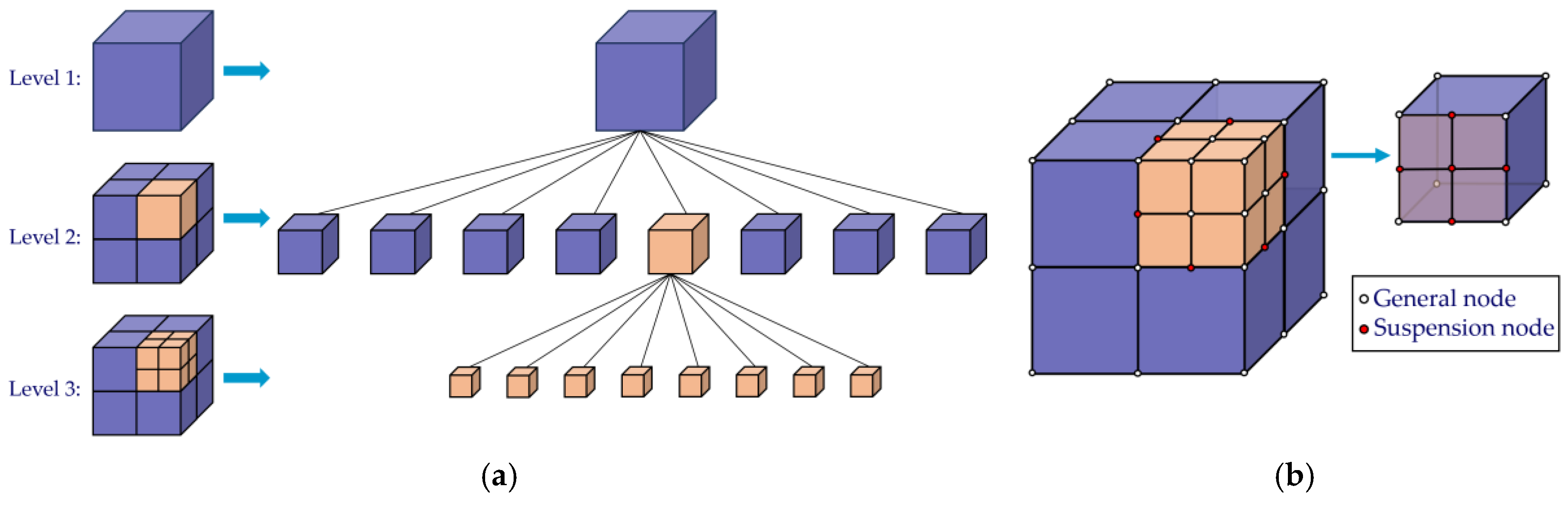
Figure 2.
Three-dimensional geometric model diagram: (a) overall model; (b) partial model.
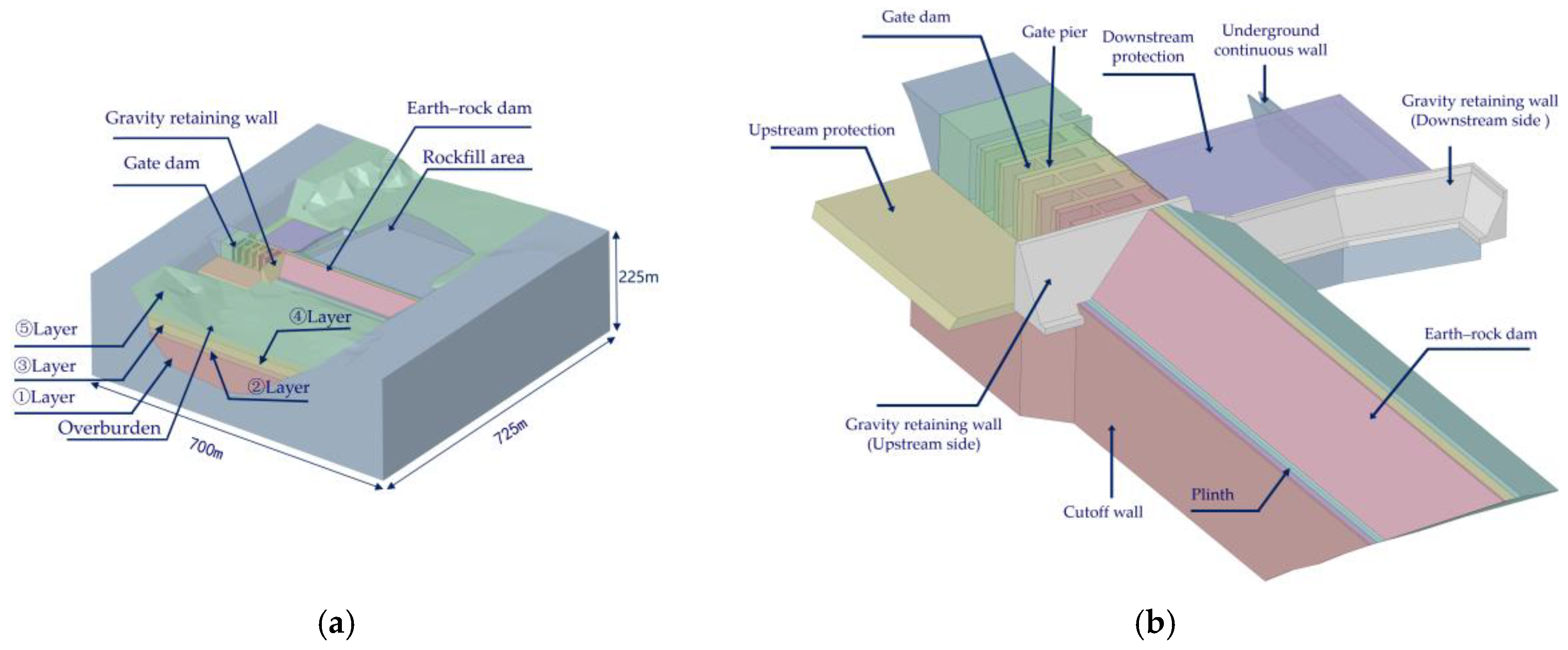
Figure 3.
Three-dimensional grid diagram of the dam (number of cells: 778,195; number of nodes: 842,876): (a) overall model; (b) partial model.
Figure 3.
Three-dimensional grid diagram of the dam (number of cells: 778,195; number of nodes: 842,876): (a) overall model; (b) partial model.
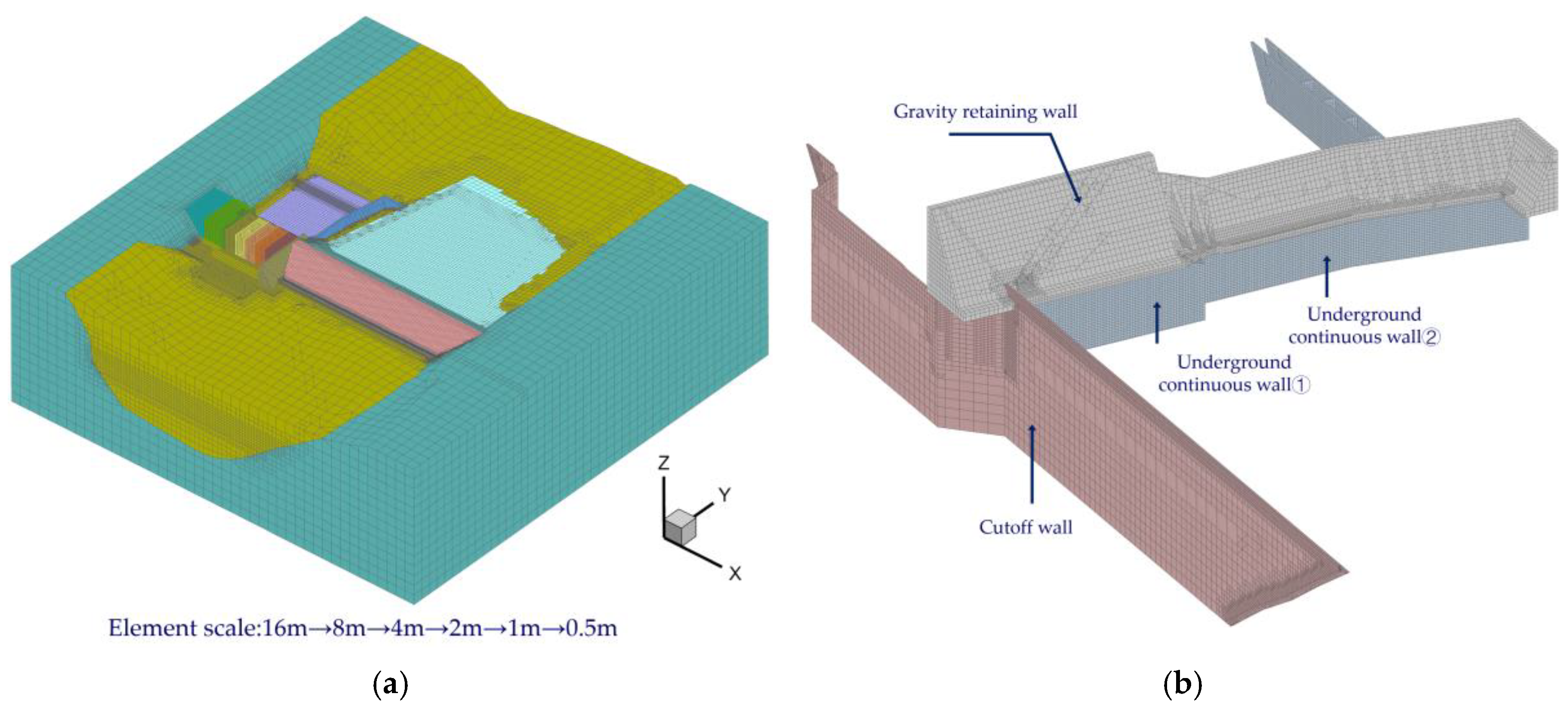
Figure 4.
Distribution pattern of vertical deformation of dams after impoundment (unit: m): (a) schematic diagram of slice position; (b) vertical deformation of the dam at different slice locations.
Figure 4.
Distribution pattern of vertical deformation of dams after impoundment (unit: m): (a) schematic diagram of slice position; (b) vertical deformation of the dam at different slice locations.
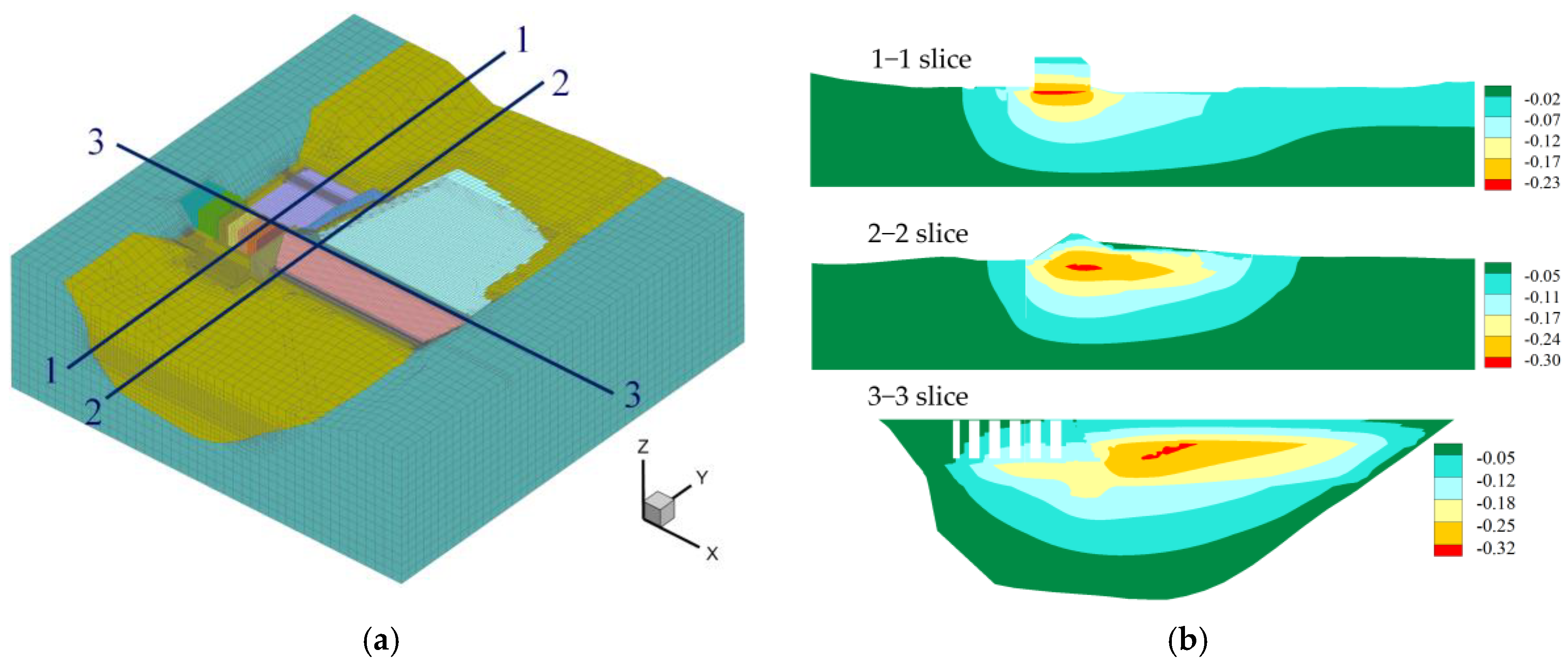
Figure 5.
Joint locations and deformation of the gate dam section after impoundment: (a) schematic diagram of joint locations; (b) seam deformation patterns.
Figure 5.
Joint locations and deformation of the gate dam section after impoundment: (a) schematic diagram of joint locations; (b) seam deformation patterns.
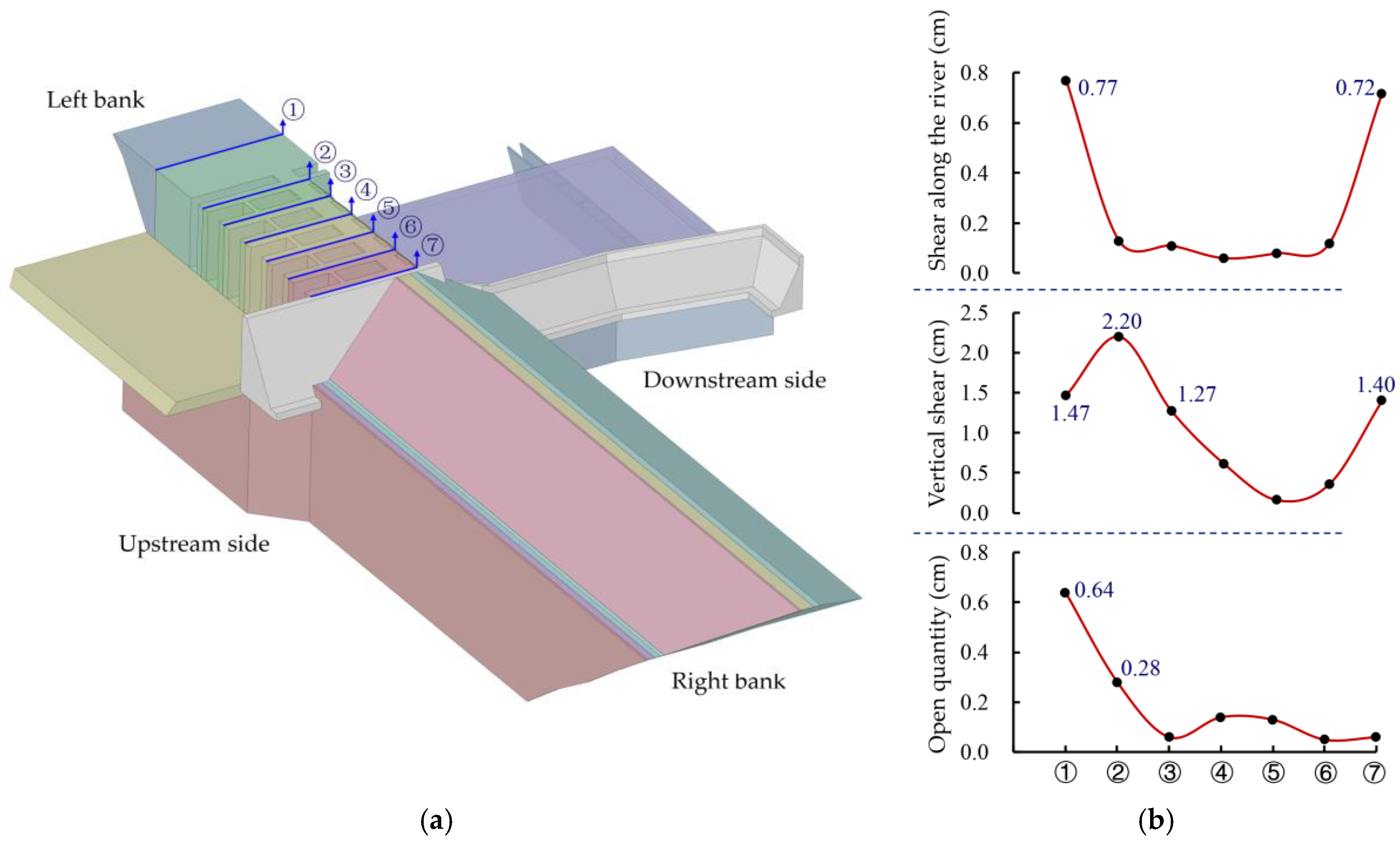
Figure 6.
Deformation patterns in the cutoff wall after impoundment (unit: m): (a) vertical settlement; (b) dam axial deformation.
Figure 6.
Deformation patterns in the cutoff wall after impoundment (unit: m): (a) vertical settlement; (b) dam axial deformation.
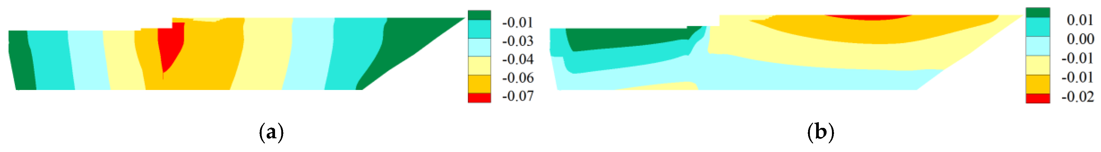
Figure 7.
Stress distribution in the cutoff wall after impoundment (unit: MPa, compressive stress is positive): (a) major principal stress; (b) minor principal stress.
Figure 7.
Stress distribution in the cutoff wall after impoundment (unit: MPa, compressive stress is positive): (a) major principal stress; (b) minor principal stress.
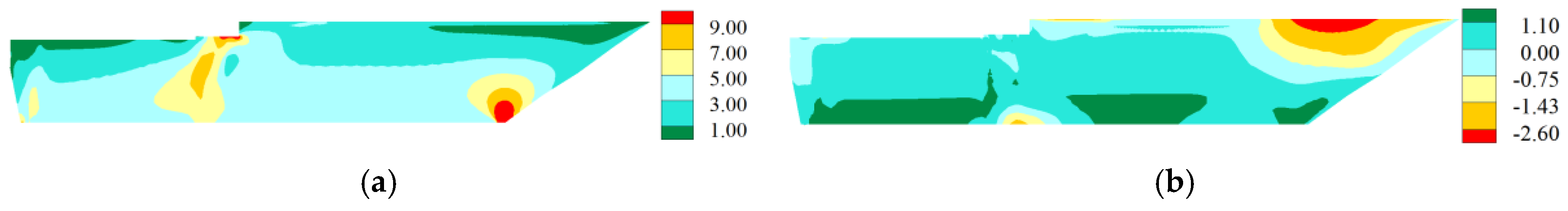
Figure 8.
Spatial deformation mode of underground continuous walls after impoundment: (a) underground continuous wall ①; (b) underground continuous wall ②.
Figure 8.
Spatial deformation mode of underground continuous walls after impoundment: (a) underground continuous wall ①; (b) underground continuous wall ②.
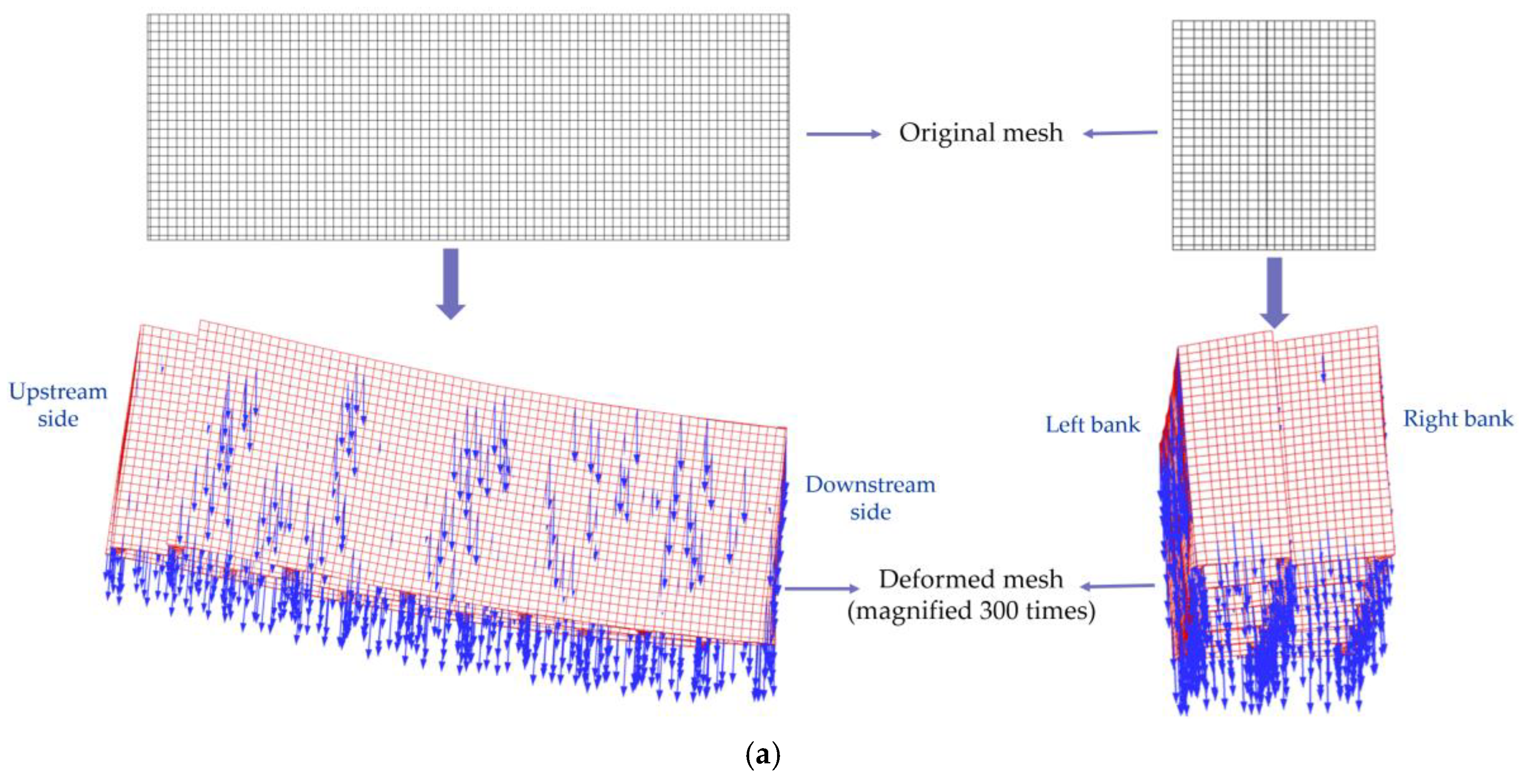
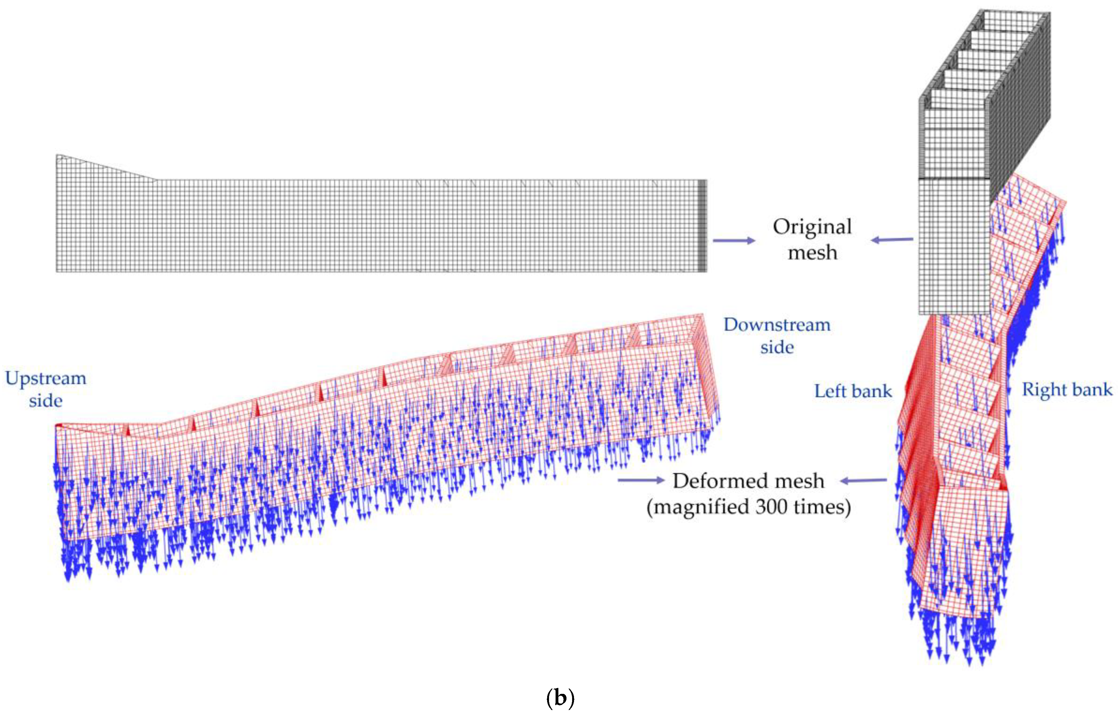
Figure 9.
Stress distribution of the underground continuous wall ① after impoundment (unit: MPa, compressive stress is positive): (a) major principal stress; (b) minor principal stress.
Figure 9.
Stress distribution of the underground continuous wall ① after impoundment (unit: MPa, compressive stress is positive): (a) major principal stress; (b) minor principal stress.
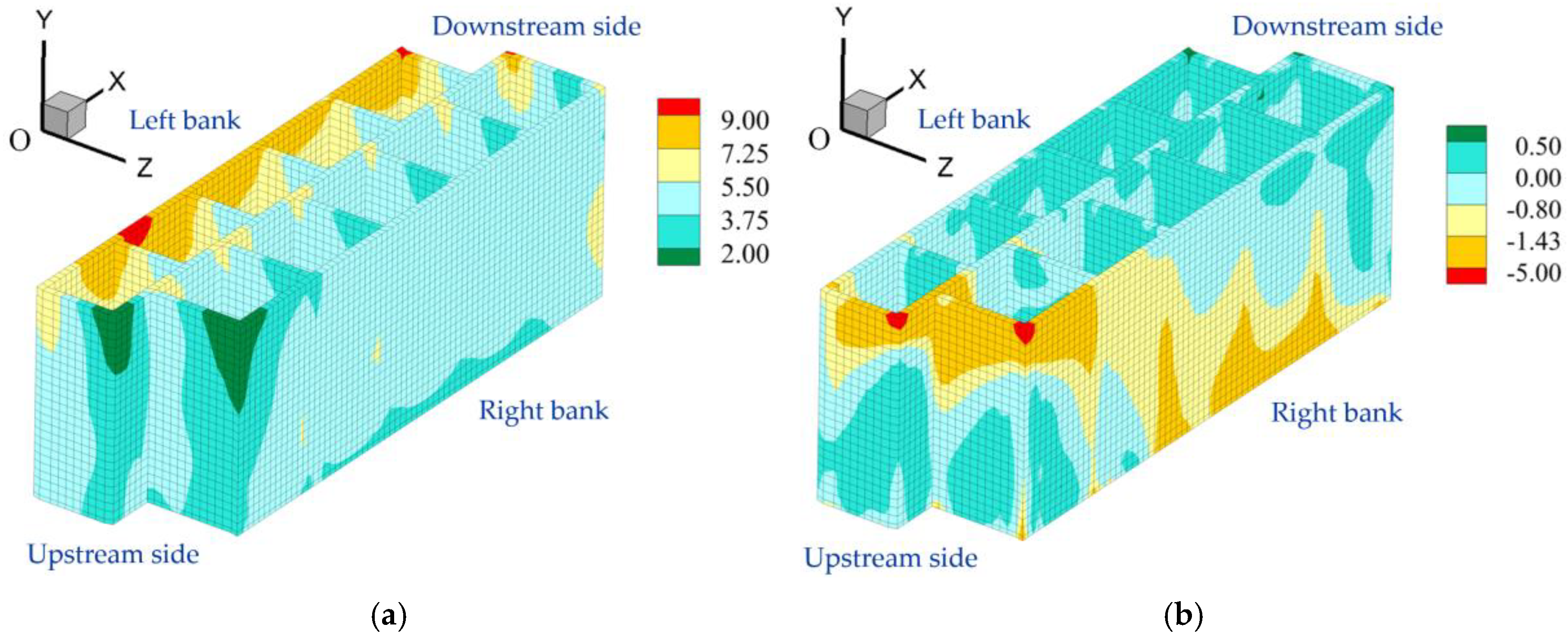
Figure 10.
Stress distribution of the underground continuous wall ② after impoundment (unit: MPa, compressive stress is positive): (a) major principal stress; (b) minor principal stress.
Figure 10.
Stress distribution of the underground continuous wall ② after impoundment (unit: MPa, compressive stress is positive): (a) major principal stress; (b) minor principal stress.
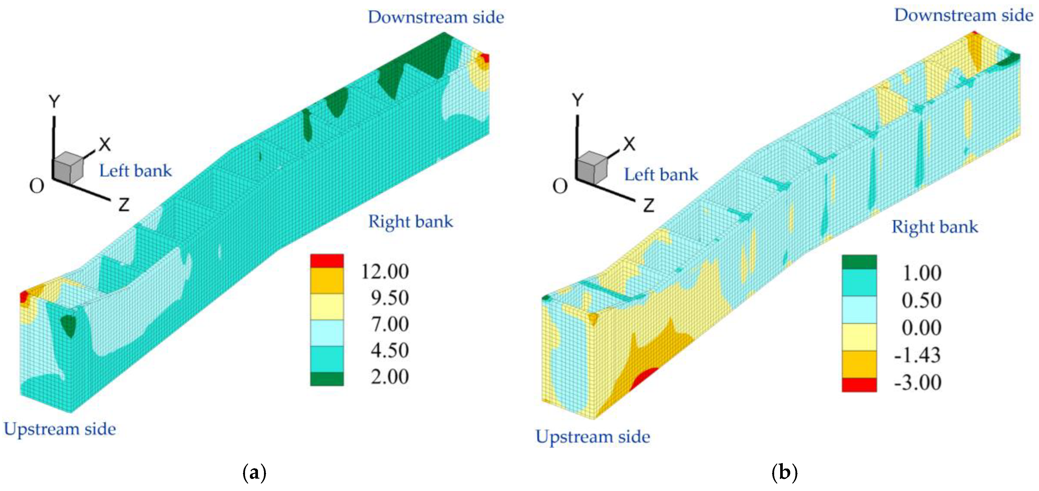

Table 1.
Parameters of the generalized plasticity model.
| Parameters | Materials for Deep Overburden | Materials for Dam | ||||||
|---|---|---|---|---|---|---|---|---|
| ①Layer | ②Layer | ③Layer | ④Layer | ⑤Layer | Cushion | Transition | Rockfill | |
| 800 | 500 | 800 | 500 | 800 | 1131 | 1131 | 1131 | |
| 700 | 450 | 700 | 450 | 700 | 1041 | 1041 | 1041 | |
| 1.68 | 1.45 | 1.68 | 1.45 | 1.68 | 1.67 | 1.67 | 1.67 | |
| 1.3 | 1.2 | 1.3 | 1.2 | 1.3 | 1.6 | 1.6 | 1.6 | |
| 0.3 | 0.3 | 0.3 | 0.3 | 0.3 | 0.12 | 0.12 | 0.12 | |
| 0.3 | 0.3 | 0.3 | 0.3 | 0.3 | 0.56 | 0.56 | 0.56 | |
| 800 | 750 | 800 | 350 | 800 | 850 | 850 | 850 | |
| 800 | 750 | 800 | 350 | 800 | 850 | 850 | 850 | |
| 0.5 | 0.5 | 0.5 | 0.5 | 0.5 | 0.2 | 0.2 | 0.2 | |
| 0.5 | 0.5 | 0.5 | 0.5 | 0.5 | 0.2 | 0.2 | 0.2 | |
| 0.5 | 0.5 | 0.5 | 0.5 | 0.5 | 0.4 | 0.4 | 0.4 | |
| 0.5 | 0.5 | 0.5 | 0.5 | 0.5 | 0.4 | 0.4 | 0.4 | |
| 10 | 10 | 10 | 10 | 10 | 5 | 5 | 5 | |
| 15 | 15 | 15 | 15 | 15 | 10 | 10 | 10 | |
| 5 | 5 | 5 | 5 | 5 | 5 | 5 | 5 | |
| 40 | 30 | 40 | 30 | 40 | 12 | 12 | 12 | |
| 0.025 | 0.02 | 0.025 | 0.02 | 0.025 | 0.015 | 0.015 | 0.015 | |
Disclaimer/Publisher’s Note: The statements, opinions and data contained in all publications are solely those of the individual author(s) and contributor(s) and not of MDPI and/or the editor(s). MDPI and/or the editor(s) disclaim responsibility for any injury to people or property resulting from any ideas, methods, instructions or products referred to in the content. |
© 2025 by the authors. Licensee MDPI, Basel, Switzerland. This article is an open access article distributed under the terms and conditions of the Creative Commons Attribution (CC BY) license (http://creativecommons.org/licenses/by/4.0/).
Copyright: This open access article is published under a Creative Commons CC BY 4.0 license, which permit the free download, distribution, and reuse, provided that the author and preprint are cited in any reuse.


