
Submitted:
02 July 2025
Posted:
03 July 2025
You are already at the latest version
Abstract
The Type IV hydrogen storage cylinder has become the preferred component for hydrogen fuel cell vehicles owing to its high hydrogen storage density, lightweight characteristics, and resistance to hydrogen embrittlement. Nevertheless, the sealing structure at the cylinder neck and its dynamic sealing performance during hydrogen refueling are critical factors governing the sealing reliability of the hydrogen storage cylinder neck. To address the sealing reliability challenges of the Type IV cylinder neck, a novel sealing structure was proposed based on principles of theoretical mechanics and mechanical design. A three-dimensional numerical model of the seal ring under hydrogen absorption-induced expansion was developed to systematically investigate the influences of the seal ring’s material properties, cross-sectional shape and radial dimensions, and groove geometry on sealing performance. Results demonstrate that a smooth transitional arc combined with a large radial cross-sectional dimension of the seal ring markedly reduces internal stress. The chamfer at the groove top exerts minimal impact on sealing characteristics (ΔP< 1.37MPa), whereas reducing the fillet radius at the groove bottom effectively mitigates stress concentration. Concerning material parameters, the elastic modulus of the seal ring exhibits a negative correlation with the sealing performance at the cylinder neck. Under cooperative sealing with double O-rings, the uniformity of contact pressure distribution improves by 10-17% relative to a single ring, accompanied by a one order of magnitude reduction in leakage rate.
Keywords:
Type IV hydrogen storage cylinders
; Sealing ring
; Sealing performance
; Structure optimization
1. Introduction
Against the backdrop of the persistent global energy crisis and escalating environmental pollution [1], hydrogen has become a vital alternative energy source due to its zero carbon emissions and renewability [2,3,4,5]. The Type IV hydrogen storage cylinder serves as a critical connecting component in onboard hydrogen storage systems, exhibiting superior overall performance. Nevertheless, challenges such as hydrogen-induced failure of the cylinder neck seal ring-including stress relaxation and blister rupture-and seal failure caused by thermal expansion urgently require resolution. Given that the sealing reliability of the cylinder neck decisively impacts the safety of onboard hydrogen storage systems, it is essential to advance research into the sealing performance of the cylinder neck.
In recent years, numerous researchers have conducted simulation and experimental studies on the sealing structure of Type IV hydrogen storage cylinders, as well as investigations into failure mechanisms and temperature rise behavior, yielding significant results. In terms of structural simulation of hydrogen storage cylinders: Xie et al.found that the valve port structure of the plastic liner significantly affects the sealing performance of hydrogen storage cylinders. Subsequently, they carried out studies on the influence of plastic liner material, valve port wall thickness, and circumferential groove machining parameters on the stress-strain behavior at the valve port of the plastic liner. Their work revealed that structural optimization of the plastic liner’s valve port contributes to enhancing the sealing reliability of Type IV hydrogen storage cylinders and provides theoretical support for the structural design of plastic liners. Su et al.proposed a novel sealing structure featuring full encapsulation of the plastic liner. Using finite element analysis, they systematically investigated the effects of O-ring clearance tolerance, hydrogen pressure, and compression ratio on the sealing performance of Type IV hydrogen storage cylinders. The results demonstrated that applying an appropriate pre-compression ratio to the O-ring significantly improves the sealing performance of the structure. Zhou et al. [8,9,10] conducted finite element analysis to investigate the sealing performance of combined sealing structures composed of O-rings, D-rings, X-rings, and wedge blocks under hydrogen-induced swelling conditions, providing theoretical guidance for the design of such composite sealing systems. Yuan et al.developed a two-dimensional axisymmetric numerical model for Type IV hydrogen storage cylinders, integrating the k-ε turbulence model and a real-gas equation of state for hydrogen. Their study revealed that optimized structural parameters and material heat capacity can effectively mitigate temperature rise during rapid hydrogen refueling, offering a theoretical foundation for the structural optimization of hydrogen storage cylinders and the safe, high-speed operation of hydrogen refueling stations. Li et al.proposed a three-dimensional thermal-fluid-structure progressive failure analysis method, which incorporates a conjugate heat transfer model, multi-field data interaction, and nonlinear damage evolution mechanisms. Their findings clarified the relationship between failure pressure degradation and rupture locations of composite gas cylinders under localized fire exposure, and demonstrated that the application of thin glass fiber/epoxy resin layers markedly enhances the fire resistance duration of composite cylinders. Wu et al.established a fatigue life prediction approach for high-pressure hydrogen storage cylinders, employing a parameterized finite element model to reveal the optimization strategy for autofrettage pressure ranges. Additionally, they elucidated the synergistic effects of metal liner thickness and fiber winding layers on fatigue failure modes under cyclic loading, providing valuable insights into improving the durability of hydrogen storage systems. In the field of experimental studies on sealing ring failure, Yamabe et al. [14,15] developed a high-pressure hydrogen durability testing platform for O-rings to investigate the effects of hydrogen pressure and temperature on blister cracking damage, hydrogen permeability, tensile properties, and hydrogen-induced swelling behavior. Bernard et al.using photoelastic experiments, discovered that under uniform compression and internal pressure, the dual bulges at the contact interface of extruded X-ring seals coalesce into a single bulge, yet the sealing performance remains effective. Shin et al. [17,18] designed a transparent photoelastic experimental loading device to systematically analyze the contact behavior and failure mechanisms of O-rings, D-rings, and X-rings under combined compression and internal pressure conditions. Their findings clarified the relationships between sealing characteristics and failure criteria for different sealing structures. In terms of failure testing of hydrogen storage cylinders, Cheng et al.investigated the multiscale structural evolution mechanisms of long-chain polyamide liners fabricated by rotational molding and injection molding during hydrogen cycling in Type IV hydrogen storage cylinders. The study revealed that the rotational molding process effectively stabilizes the α’ crystalline phase, thereby achieving uniform crystal size distribution, which contributes to enhancing the structural reliability of composite hydrogen storage cylinders. Qin et al. developed an experimental platform to investigate hydrogen leakage in onboard hydrogen supply pipelines and quantitatively analyzed the evolution of hydrogen mass leakage rates under the coupled influence of loosening angles, orifice geometry, and system pressure. Furthermore, they proposed a correction method for the leakage flow coefficient based on extrapolated experimental data. In terms of hydrogen storage cylinder refueling thermal response studies, N. de Miguel et al.proposed an inverse prediction method for internal gas temperature evolution by monitoring the external wall temperature field. Through cyclic high-pressure hydrogen charge-discharge experiments, they revealed the thermo-mechanical coupling mechanisms of Type III and Type IV hydrogen storage cylinders, and validated the influence of filling rate, cylinder materials, and initial thermal state on the internal gas temperature dynamics and structural thermal response. Daniele et al.combining CFD simulations with experimental data, elucidated the regulatory effect of pre-cooling strategies on the evolution of the thermal field during the rapid refueling process of high-pressure hydrogen storage cylinders. Jun-ichi Tomioka et al.experimentally investigated the mechanisms governing fatigue strength variation of hydrogen storage cylinders under different ambient temperatures. The study clarified that the mismatch in thermal expansion coefficients between carbon fiber reinforced composites and aluminum alloys induces a temperature-dependent self-reinforcing mechanism, which accelerates carbon fiber fatigue and significantly reduces the service life of Type IV hydrogen storage cylinders in high-temperature environments.
In summary, existing research has predominantly concentrated on failure tests of hydrogen storage cylinder bodies and the strength of sealing structures, with extensive studies on hydrogen temperature rise characteristics and fatigue burst tests. However, investigations into factors influencing the sealing performance of the hydrogen storage cylinder neck and the internal damage mechanisms of the seal ring remain limited. The sealing structure of the cylinder neck and the sealing properties of the seal ring exert a significant impact on the sealing reliability of the Type IV hydrogen storage cylinder neck. To explore the sealing characteristics of onboard Type IV hydrogen storage cylinders, a three-dimensional numerical model of the seal ring under hydrogen absorption-induced expansion was developed based on a novel cylinder neck sealing structure. This model was employed to analyze the effects of the seal ring’s elastic modulus, cross-sectional shape, radial dimensions, and sealing groove structural parameters on the sealing performance of the Type IV hydrogen storage cylinder.
2. Basic Equations
Based on hydrogen diffusion theory, the constitutive equation of the seal ring is established. As shown in Figure 1, the seal structure of a Type IV hydrogen storage bottle is assumed to be affected only by hydrogen pressure and hydrogen-induced strain, without considering the cumulative fatigue damage of the seal ring caused by temperature. According to Fick’s second law, the control equation for hydrogen diffusion is given in Equation (1):
In the equation, DH is the hydrogen diffusion coefficient, ∂CH/∂τ is the time derivative, and CH is the hydrogen concentration function.
In the finite element model, the material of the PTFE seal ring was set as hyperelastic for research purposes. To examine the hyperelastic properties of the seal ring material, the three-parameter Mooney-Rivlin model was used, whose function can be expressed as Equation (2):
where W is the strain energy density, I1 and I2 are the first and second strain tensor invariants, and C10, C01, and C20 are the Mooney-Rivlin coefficients.
The stress-strain relationship of the seal ring can be described by Equation (3) [27]:
Considering hydrogen-induced strain on the seal ring, the total strain on the seal ring is determined by Equation (4):
In the formula, εij is the total strain of the seal ring, εije is the superelastic strain of the seal ring, and εijH is the hydrogen-induced strain of the seal ring.
Assuming that hydrogen-induced strain is pure strain and that the volume increase caused by swelling is linearly proportional to hydrogen concentration, the hydrogen-induced strain of the seal ring is determined by Equation (5) [15]:
In the equation: αH is the linear proportional coefficient, ∆CH is the change in hydrogen concentration, and δij is the Kronecker delta.
Under the action of high-pressure hydrogen gas and pre-compression ratio, the contact stress generated by the sealing ring is:
Substituting equations (4) and (5) into equation (6) gives:
In the formula, E is the elastic modulus of the seal ring, MPa; μ is the Poisson’s ratio of the seal ring.
3. Model Building
3.1. Design of the Sealing Structure
Figure 1 presents a schematic of the sealing structure of a Type IV hydrogen storage cylinder, comprising a carbon fiber winding layer, plastic liner, metal valve seat, sleeve, pressure relief ring, and sealing ring. Enclosed by the sleeve, a composite sealing structure consisting of the O-ring and pressure relief ring is formed. When high-pressure hydrogen is introduced into the storage cylinder, sealing is achieved by axially compressing the O-ring. The pressure relief ring reduces the load on the sealing ring, protecting the sealing assembly and mitigating damage to the sealing ring. The design dimensions are provided in Table 1.
3.2. Building of Finite Element Models
3.2.1. Material Parameters
The sealing structure of the Type IV hydrogen storage cylinder examined in this study is established based on a literature review. The plastic liner material is HDPE (high-density polyethylene), the carbon fiber material is T395, the pressure relief ring is made of aluminum alloy, the sealing ring material is PTFE (polytetrafluoroethylene), and the sleeve is made of PEEK (polyether ether ketone). Detailed parameters are listed in Table 2.
3.2.2. Grid Independence Verification
To ensure a balance between computational accuracy and efficiency, a mesh independence verification was performed for the sealing structure of the Type IV hydrogen storage cylinder. A local coordinate system was established, and the sealing ring region was meshed with tetrahedral elements. As shown in Figure 2, mesh sizes of 0.5mm, 1mm, 1.5mm, 2mm, 2.5mm, and 3mm were selected for the sealing ring, with the corresponding number of mesh elements listed in Table 3. The peak internal stress and contact stress were used to evaluate the appropriateness of the mesh size. When the relative error of stress results falls below 5%, the mesh is considered sufficiently accurate. It was found that when the mesh size of the sealing ring is 2mm, the errors in peak internal stress and contact stress converge, and both the element count and mesh distribution reach optimal levels. Therefore, a mesh size of 2mm was adopted for the sealing ring.
3.2.3. Boundary Condition Settings
In the three-dimensional numerical model of the Type IV hydrogen storage cylinder port structure, a total of five contact pairs are defined, including metal valve seat-carbon fiber, metal valve seat–plastic liner, and metal valve seat–sealing ring. The contact between the sleeve and the plastic liner is defined as bonded. The friction coefficient between the plastic liner and the sealing ring is set to 0.02, while the friction coefficient for all other contact pairs is set to 0.1. Small deformation and sliding effects are considered, and the penalty contact algorithm is used for the contact calculations. Under ultimate operating conditions, a circumferential load of 70MPa is applied to the inner surface of the plastic liner, and an axial load of 35MPa is applied to the metal valve seat. In the numerical model, circumferential constraints are imposed on the outer surface of the valve seat, and fixed constraints are applied to the external metal bands of the cylinder.
3.2.4. Finite Element Model Verification of Sealed Structures
Assuming that the finite element model of the Type IV hydrogen storage cylinder is a thin-walled cylinder, according to the thin-film theory [6], the circumferential stress and axial stress are calculated as follows:
In the formula, σθ is the circumferential stress, MPa; σφ is the axial stress, MPa; P is the internal pressure, MPa; D is the outer diameter of the inner cylinder, m; δ is the thickness of the carbon fibre winding layer, m.
The theoretical values of the hoop stress and axial stress calculated from the above equations are 896MPa and 448MPa, respectively. As shown in Figure 3, finite element analysis was conducted to assess the hoop and axial stresses along the S1 plane path of the hydrogen storage cylinder. The finite element results show that the hoop stress and axial stress at the S1 plane are 882.4MPa and 476.2MPa, respectively, demonstrating good agreement with the theoretical values and validating the accuracy of the finite element model for the Type IV hydrogen storage cylinder.
4. Results Analysis and Discussion
The internal stress, deformation, and contact stress of the sealing ring are critical indicators characterizing the sealing reliability of the cylinder port. Fluid leakage is likely to occur when the maximum contact stress of the sealing ring is lower than the sealing medium pressure [24,25]. Excessive internal stress within the sealing ring may lead to crack initiation and stress relaxation, posing potential safety risks to the Type IV hydrogen storage cylinder. Therefore, a parametric optimization study was conducted on the sealing structure of the cylinder port by investigating the effects of the sealing ring’s elastic modulus, cross-sectional shape, radial dimensions, and sealing groove structural parameters on the sealing performance.
4.1. Seal Cross-Section Shape
As shown in Figure 4, under conditions of equal cross-sectional area, the effects of O-shaped, elliptical, trapezoidal, and rectangular cross-sectional shapes on sealing performance were analysed.
Figure 4a illustrates the contact stress distribution for sealing rings with different cross-sectional geometries. The contact stress on the innermost side of the sealing ring is greater than that on the outermost side, primarily due to the significantly higher elastic modulus of the metal valve seat compared to the plastic liner. The elastic deformation of the plastic liner increases the contact area between the liner and the sealing ring, whereas the limited deformation of the valve seat results in a smaller contact area, leading to localized stress concentrations at the sealing interface. The results reveal that sealing rings with trapezoidal and rectangular cross-sections exhibit higher and more uniform contact stress distributions compared to elliptical and O-ring cross-sections. In the case of the trapezoidal sealing ring, the difference in contact area between the inner and outer surfaces results in elevated contact stress on the outer side.
Figure 4b illustrates the internal stress distribution for sealing rings with different cross-sectional geometries. In the rectangular and trapezoidal sealing rings, stress concentrations occur at the corners, accompanied by fracture-prone damage propagating inward along the diagonal directions. The maximum internal stress in these regions exceeds the compressive strength limit of the PTFE material, posing a significant risk of structural failure. In contrast, the O-ring and elliptical sealing rings exhibit stress concentrations primarily in the interior, with the stress propagating outward. The overall stress distribution presents a characteristic dumbbell-shaped pattern, indicating two symmetric stress peaks along the inner and outer contact regions. This distribution is more favorable for mitigating localized damage compared to sharp corner geometries.
Figure 4c presents the internal deformation contour maps of sealing rings with different cross-sectional shapes. The internal deformation uniformly decreases from the outer contact surface toward the inner contact surface and exhibits vertical symmetry. In terms of deformation magnitude, the largest deformation occurs at the contact interface between the sealing ring and the plastic liner, while the smallest deformation occurs at the interface between the sealing ring and the sealing groove, which is attributed to the material’s elastic modulus. Furthermore, as shown in Figure 4d, the stress and strain responses of the O-ring remain within the allowable material strength limits. Therefore, O-rings and elliptical sealing rings exhibit superior sealing performance compared to rectangular and trapezoidal designs. However, localized stress concentrations and non-uniform deformation are observed in the elliptical sealing ring, which may lead to potential fracture initiation along the slip direction.
4.2. O-Ring Cross-Sectional Radial Dimensions
The machining size of the sealing groove in the proposed Type IV hydrogen storage cylinder port sealing structure is constrained, with the radial dimension of the O-ring cross section designed within the range of 6 mm to 10mm. Figure 5 illustrates the effect of the O-ring cross-sectional radial dimension on its sealing performance. As the radial dimension increases, the radius of curvature correspondingly increases, leading to reductions in maximum contact stress and internal stress, while the deformation magnitude increases. This phenomenon is attributed to the increased radial dimension enlarging the contact area between the O-ring, the plastic liner, and the sealing groove, which simultaneously alters the compression rebound behavior, thus reducing the compression ratio.
4.3. Sealed Groove Structure
Due to the yield strength limitation of the O-ring and the machining constraints of the sealing groove, an O-ring with a 9mm radial dimension was selected to investigate the influence of the sealing groove bottom fillet radius and the groove top chamfer size on the sealing performance of the cylinder port.
As shown in Figure 6a, as the sealing groove bottom fillet radius increases, the contact and internal stresses of the O-ring increase, while the deformation magnitude decreases. When the fillet radius reaches 3.75mm, all three parameters sharply increase. This phenomenon occurs because the O-ring is fully compressed and completely fills the groove once the fillet radius exceeds a critical value, resulting in constrained deformation and significantly intensified stress concentration, thus accelerating damage to the O-ring.
As shown in Figure 6b, as the sealing groove top chamfer size increases, the O-ring maximum contact stress initially increases and then stabilizes, while the maximum internal stress initially decreases before rising, and the deformation magnitude remains relatively stable. Given that the magnitudes of variation in contact and internal stresses are minor, their effects on the sealing performance of the Type IV hydrogen storage cylinder port are negligible. Therefore, a chamfer facilitating assembly can be machined at the groove top without affecting the stress distribution of the valve seat.
4.4. Sealing Groove Machining Position
The machining position of the sealing groove is defined as the distance between its center plane and surface S2 shown in Figure 1. Figure 7 illustrates the influence of the sealing groove machining position on the sealing performance of the O-ring. As the machining position moves farther away, the O-ring maximum contact stress initially increases and then stabilizes, while the maximum internal stress gradually decreases and then stabilizes. The deformation magnitude remains nearly constant. This behavior results from the constant and uniformly distributed hydrogen pressure condition, under which the O-ring experiences approximately constant pressure and compression ratio regardless of the machining position.
4.5. Double O-Ring Installation Spacing
Due to the machining dimensional limitations of the metal valve seat, the effect of double O-ring installation spacing on sealing performance is investigated. To ensure uniform stress distribution on the valve seat, increasing the installation spacing appropriately can significantly reduce the internal stress within the sealing rings. Therefore, the maximum installation spacing for the double O-rings is set to L=23mm for analysis. As shown in Figure 8 and Figure 9, the stress and strain evolution trends of the double O-rings are similar to those of the single O-ring in Figure 4a–c, although slight differences in magnitude are observed. Furthermore, compared to the single O-ring configuration, the cooperative double O-ring sealing exhibits fewer stress concentration points in the contact region.
Figure 10 illustrates the sealing performance curves of the double O-rings at the port of the hydrogen storage cylinder under different installation spacings. As the installation spacing between the double O-rings increases, the maximum contact stress, internal stress, and deformation magnitude of the O-rings gradually decrease accordingly. This is because the contact surface between the double O-rings and the plastic liner can be modeled as a simply supported beam, where the bending moment acting on the O-ring is minimal, resulting in reduced stress and deformation values. The cooperative sealing effect of multiple O-rings significantly reduces the internal stress within the sealing rings and improves sealing performance by an order of magnitude.
4.6. O-Ring Elastic Modulus
Under the action of high-pressure hydrogen, the elastic modulus of the O-ring varies proportionally with its hardness [26,27]. The elastic modulus values of the O-rings studied in this paper are 560MPa, 660MPa, and 760MPa. When the elastic modulus exceeds 760MPa, the internal stress within the O-ring surpasses the compressive strength of the material, thereby accelerating the failure process of the sealing structure at the cylinder port.
As shown in Figure 11a–c, the stress and deformation contours under different elastic modulus conditions exhibit diagonal symmetry. The results indicate that both the maximum internal stress and contact stress of the O-rings increase with the elastic modulus, while the corresponding deformation decreases. Under the cooperative sealing effect of the double O-rings, it is recommended to minimize the radial cross-sectional size of each O-ring within the allowable machining range. A reduction in radial cross-sectional size leads to higher internal stress and contact stress, while the maximum deformation occurs when the radial cross-sectional diameter of the double O-rings is 8mm. Under identical loading conditions, the double O-ring cooperative sealing demonstrates superior performance compared to single O-ring configurations, as it not only ensures stable contact stress distribution along the sealing interface but also effectively reduces the internal stress within the O-rings.
Figure 11a–c present stress and deformation contour maps under varying elastic moduli, exhibiting symmetric distribution along the diagonal. Both the maximum internal and contact stresses of the O-ring increase with rising elastic modulus, whereas the deformation magnitude decreases. Within the manufacturable range, the cross-sectional radial dimension of double O-rings should be minimized to optimize sealing performance. Under this condition, contact and internal stresses increase, with deformation peaking at a radial dimension of 8mm. Compared to a single O-ring, the cooperative sealing effect of double O-rings is more pronounced under identical conditions, primarily by maintaining stable contact stress at the sealing interface while significantly reducing internal stress.
Figure 12, Figure 13 and Figure 14 demonstrate that variations in elastic modulus do not affect the patterns of stress and deformation. However, at elastic moduli of 660MPa and 760MPa, the maximum internal stress of the double O-rings approaches the yield strength of the PTFE material. As shown, the maximum internal stress nears 100MPa, thereby accelerating O-ring failure. When the elastic modulus is 560MPa, the maximum internal stress is 82.6MPa. Consequently, analyzing the stress-strain behavior of the O-rings at an elastic modulus of 560MPa holds greater practical significance.
5. Conclusions
In this study, a numerical model was developed to investigate the influence mechanisms of sealing ring hydrogen-induced expansion and key structural parameters on the sealing performance of Type IV hydrogen storage cylinders following hydrogen filling. The study systematically revealed how the sealing groove structure, elastic modulus of the sealing ring, cross-sectional shape, and radial dimensions affect the sealing performance. These findings provide important theoretical support for optimizing the sealing structures of high-pressure hydrogen storage systems. The results indicate that:
(1) A sealing ring cross-section with smooth transition arcs and a large radial dimension can significantly reduce internal stress, thus enhancing the sealing performance of Type IV hydrogen storage cylinders. Additionally, the curvature radius of the outer arc of the sealing ring should be smaller than that of the inner arc.
(2) During the fabrication of the sealing groove, increasing the groove spacing and its distance from the cylinder’s outer end face is favorable for enhancing sealing performance. The chamfer at the top of the groove has a negligible influence on sealing characteristics (ΔP < 1.37 MPa), whereas reducing the bottom fillet radius effectively mitigates stress concentration.
(3) For O-rings made of PTFE material, those with an elastic modulus value less than 760 MPa should be selected as sealing components, and the elastic modulus of the O-ring is negatively correlated with sealing performance.
(4) The dual O-ring cooperative sealing improves the uniformity of contact pressure distribution by 10-17% compared to a single O-ring, while the leakage rate is reduced by an order of magnitude. Furthermore, the radial cross-sectional dimension of the first O-ring has a significant impact on sealing failure.
References
- Chen, M.; Hu, Z.; et al. Progress of key technology research on Ⅳ type on-board hydrogen storage cylinders. Pressure Vessel Technology 2020, 37, 39–50. [Google Scholar]
- Zheng, J.; Liu, X.; et al. Development of high pressure gaseous hydrogen storage technologies. Int J Hydrogen Energy 2012, 37, 1048–1057. [Google Scholar] [CrossRef]
- Dodds, P.E.; Staffell, I.; et al. Hydrogen and fuel cell technologies for heating: A review. Int J Hydrogen Energy 2015, 40, 2065–2083. [Google Scholar] [CrossRef]
- Sharma, S.; Ghoshal, S.K.; et al. Hydrogen the future transportation fuel: From production to applications. Renew Sustain Energy Rev 2015, 43, 1151–1158. [Google Scholar] [CrossRef]
- Marchi, C.S.; Somerday, B.P.; Robinson, S.L.; et al. Permeability, solubility and diffusivity of hydrogen isotopes in stainless steels at high gas pressures. Int J Hydrogen Energy 2007, 32, 100–116. [Google Scholar] [CrossRef]
- Xie, P.; Chen, Y.; Wang, X.; et al. Type Ⅳ High Pressure Hydrogen Storage Cylinder Seal Structure Design and Performance Simulation Research. Pressure Vessel Technology 2023, 40, 37–44. [Google Scholar]
- Su, H.; He, C.; et al. 70 MPa Vehicle Type IV Hydrogen Storage Cylinder Bottle mouth sealing technology research. China Special Equipment Safety 2023, 39, 9–15. [Google Scholar]
- Zhou, C.; Zheng, J.; Gu, C.; Zhao, Y.; et al. Sealing performance analysis of rubber O-ring in high-pressure gaseous hydrogen based on finite element method. Int J Hydrogen Energy 2017, 42, 11996–12004. [Google Scholar] [CrossRef]
- Zhou, C.; Chen, G.; Liu, P.; et al. Finite Element Analysis of Sealing Performance of Rubber D-Ring Seal in High-Pressure Hydrogen Storage Vessel. J Fail. Anal. and Preven. 2018, 18, 846–855. [Google Scholar] [CrossRef]
- Zhou, C.; He, M.; Chen, G.; et al. Numerical study on sealing characteristic of rubber X-ring exposed to high-pressure hydrogen by considering swelling effect. Industrial Lubrication and Tribology 2019, 71, 133–138. [Google Scholar] [CrossRef]
- Yuan, K.; Liu, Z.; Li, X.; et al. Effects of structure parameter and material property on thermal performance of on-board hydrogen storage tanks during fast refueling. Int J Hydrogen Energy 2024, 81, 1145–1155. [Google Scholar] [CrossRef]
- Li, Q.; Huang, G.; Qi, L.; et al. Thermal-fluid-structure coupling progressive failure analysis for the type III composite cylinder under localized fire. Int J Hydrogen Energy 2023. [CrossRef]
- Wu, E.; Zhao, Y.; Zhao, B.; et al. Fatigue life prediction and verification of high pressure hydrogen storage vessel. Int J Hydrogen Energy 2021, 46, 30412–30422. [Google Scholar] [CrossRef]
- Yamabe, J.; Koga, A.; Nishimura, S.; et al. Failure behavior of rubber Oring under cyclic exposure to high-pressure hydrogen gas. Eng Fail Anal 2013, 35, 193–205. [Google Scholar] [CrossRef]
- Yamabe, J.; Fujiwara, H.; Nishimura, S. Fracture analysis of rubber sealing material for high pressure hydrogen vessel. J Environ Eng 2011, 6, 53–68. [Google Scholar] [CrossRef]
- Bernard, A.; Hawong, J.; et al. Contact behavior analysis of elastomeric X-ring under uniform squeeze rate and internal pressure before and after forcing-out using the photo elastic experimental hybrid method. J Mech Sci Technol 2015, 29, 2157–2168. [Google Scholar] [CrossRef]
- Lim, H.; Hawong, J.; Shin, D.; et al. A study on the behaviors of the D-ring with a curvature radius using the photoelastic experimental hybrid method. J Mech Sci Technol 2015, 29, 3395–3404. [Google Scholar] [CrossRef]
- Shin, D.; Hawong, J.; et al. Contact behavior analysis of X-ring under internal pressure and uniform squeeze rate using photo elastic experimental hybrid method. J Mech Sci Technol 2014, 28, 4063–4073. [Google Scholar] [CrossRef]
- Cheng, L.; Qi, L.; et al. Effects of hydrogen cycling on the performance of 70 MPa high-pressure hydrogen storage tank liners formed by different processes. Int J Hydrogen Energy 2024, 83, 499–511. [Google Scholar] [CrossRef]
- Qin, C.; Tian, Y.; et al. Quantitative analysis of hydrogen leakage flow measurement and calculation in the on-board hydrogen system pipelines. Int J Hydrogen Energy 2024, 89, 1025–1039. [Google Scholar] [CrossRef]
- de Miguel, N.; Ortiz Cebolla, R.; et al. Compressed hydrogen tanks for on-board application: Thermal behaviour during cycling. Int J Hydrogen Energy 2015, 40, 6449–6458. [Google Scholar] [CrossRef]
- Melideo, D.; Baraldi, D.; et al. CFD model performance benchmark of fast filling simulations of hydrogen tanks with pre-cooling. Int J Hydrogen Energy 2014, 39, 4389–4395. [Google Scholar] [CrossRef]
- Tomioka, J.-I.; Kiguchi, K.; et al. Influence of temperature on the fatigue strength of compressed-hydrogen tanks for vehicles. Int J Hydrogen Energy 2011, 36, 2513–2519. [Google Scholar] [CrossRef]
- Zhang, H.; Zhang, J.; et al. Static and Dynamic Sealing Performance Analysis of Rubber D-Ring Based on FEM. J Fail. Anal. and Preven 2016, 16, 165–172. [Google Scholar] [CrossRef]
- Li, X.; Peng, G.; et al. Prediction of seal wear with thermal–structural coupled finite element method. Finite Elements Anal. Des 2014, 83, 10–21. [Google Scholar]
- Singh, H.K.; et al. Lifetime prediction and durability of elastomeric seals for fuel cell applications [Doctoral thesis]. Virginia Polytechnic Institute and State University 2009.
- Zahabi, S.R.; et al. The micro/macro mechanical approach of reinforced braid composite used in tribology. J. Compos. Mater 2021, 55, 3813–3825. [Google Scholar] [CrossRef]
Figure 1.
Type IV hydrogen storage cylinder sealing structure.
Figure 2.
Verification of seal ring grid independence.
Figure 3.
Finite element model verification and boundary conditions for Type IV hydrogen storage cylinders.
Figure 3.
Finite element model verification and boundary conditions for Type IV hydrogen storage cylinders.
Figure 4.
(a) Stress cloud diagram of seal ring contact; (b) Deformation cloud diagram of seal ring; (c) Internal stress cloud diagram of seal ring; (d) Bar chart of peak contact stress, deformation, and internal stress of seal ring.
Figure 4.
(a) Stress cloud diagram of seal ring contact; (b) Deformation cloud diagram of seal ring; (c) Internal stress cloud diagram of seal ring; (d) Bar chart of peak contact stress, deformation, and internal stress of seal ring.
Figure 5.
Effect of cross-sectional radial dimensions on sealing performance.
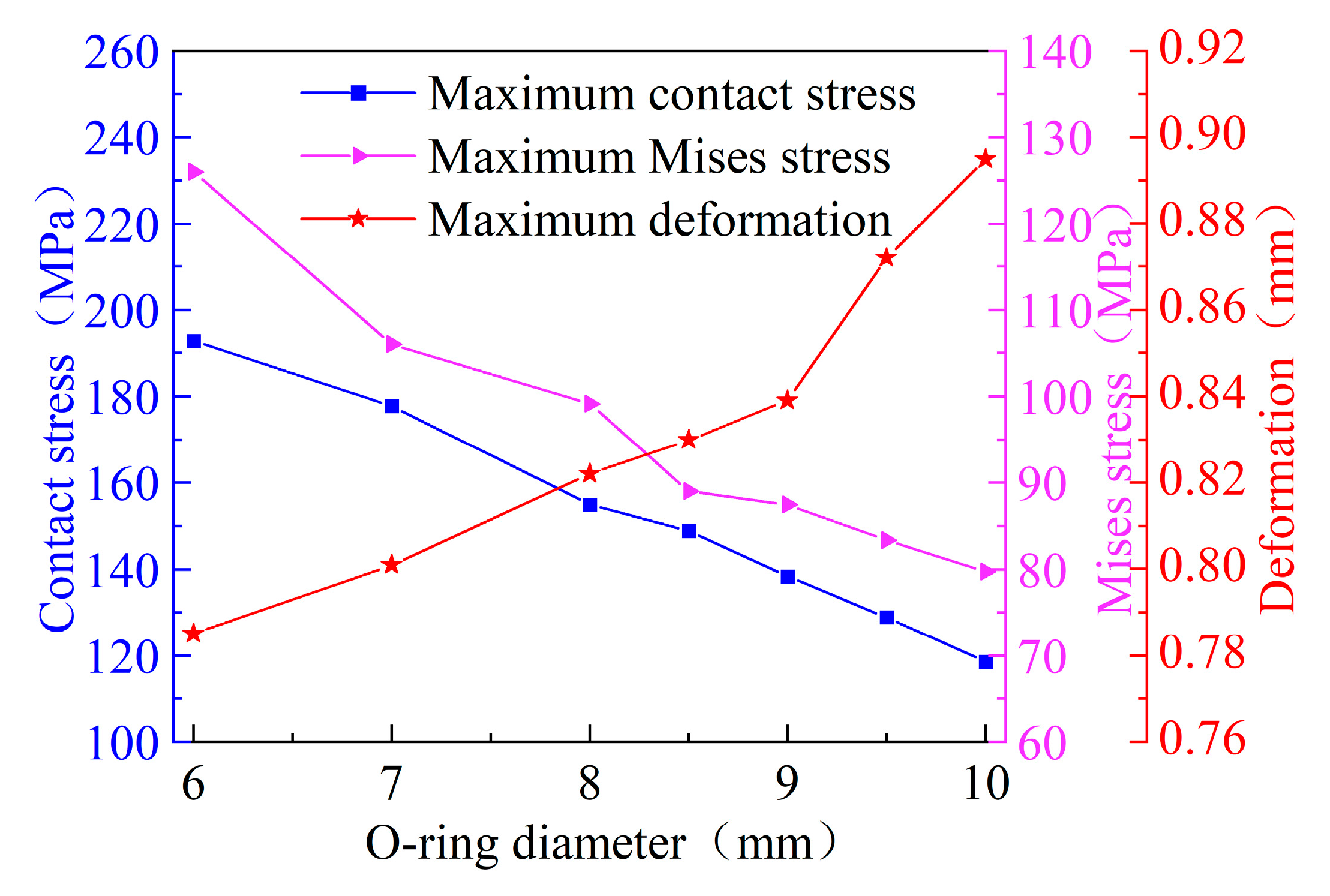
Figure 6.
Effect of groove structure parameters on sealing performance.
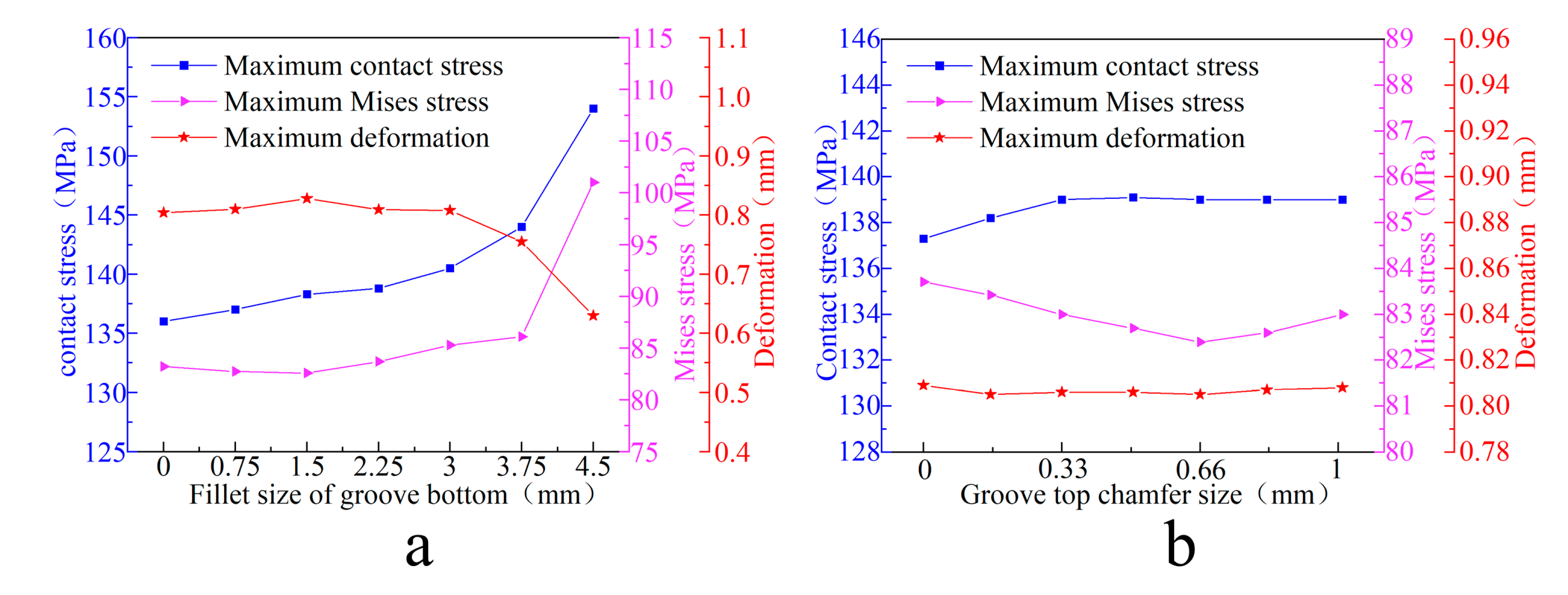
Figure 7.
The effect of machining position on sealing performance.
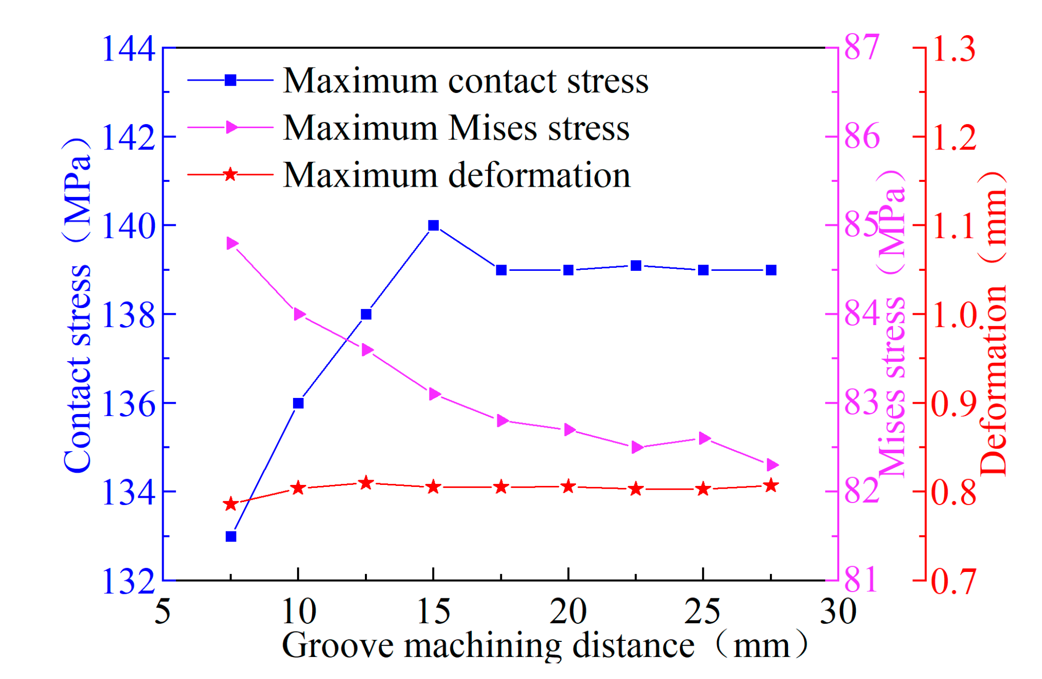
Figure 8.
Contact stress cloud of seal spacing L=23mm.
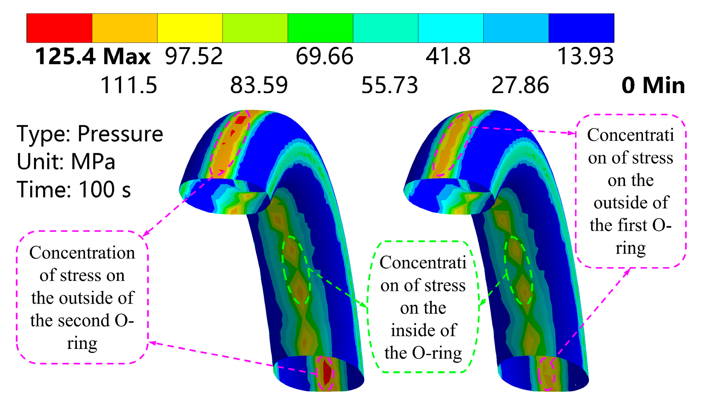
Figure 9.
(a) Deformation cloud of seal spacing L=23mm;(b) Stress cloud of sealing ring spacing L=23mm.
Figure 9.
(a) Deformation cloud of seal spacing L=23mm;(b) Stress cloud of sealing ring spacing L=23mm.
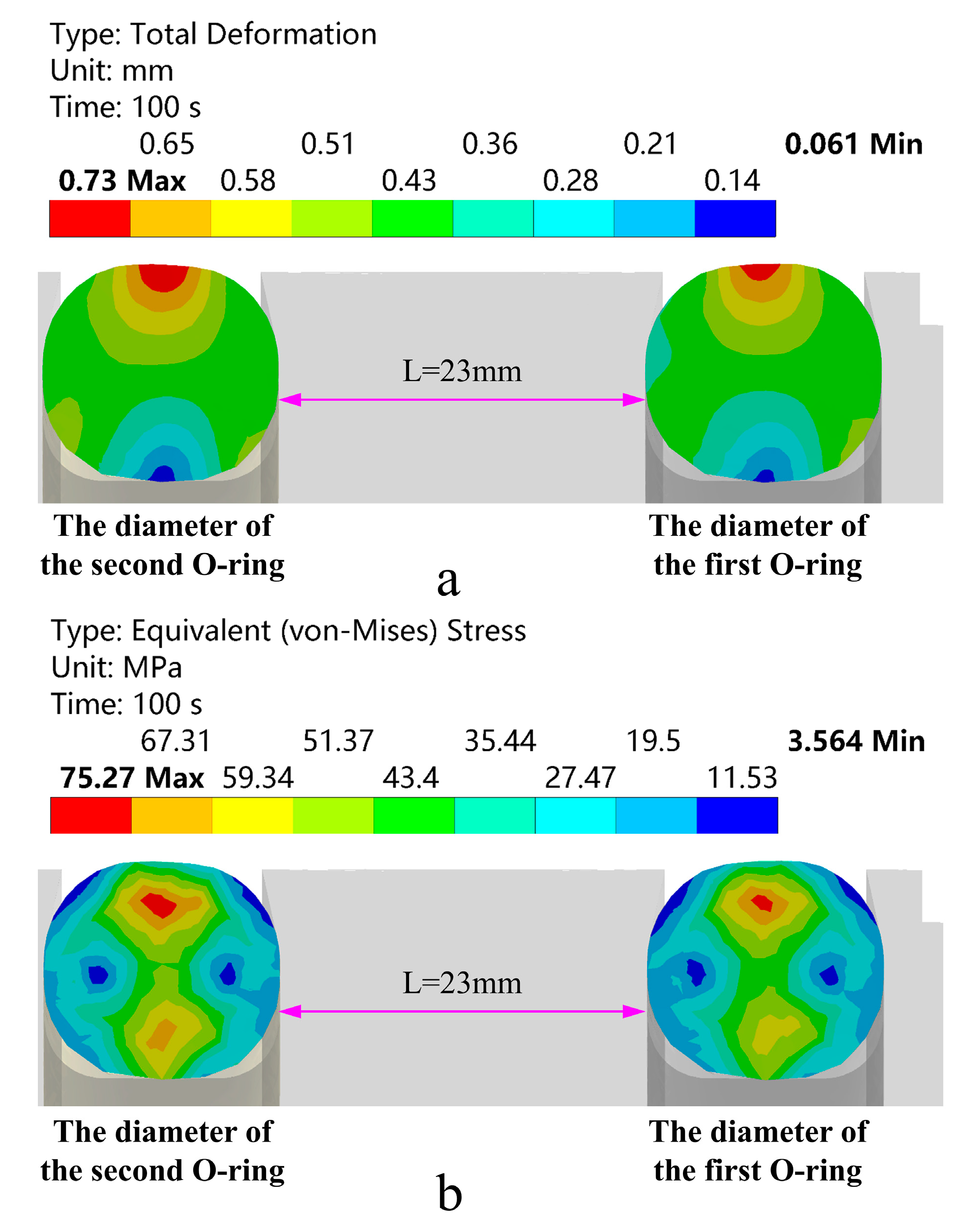
Figure 10.
Influence of sealing ring installation spacing on bottle mouth sealing performance.
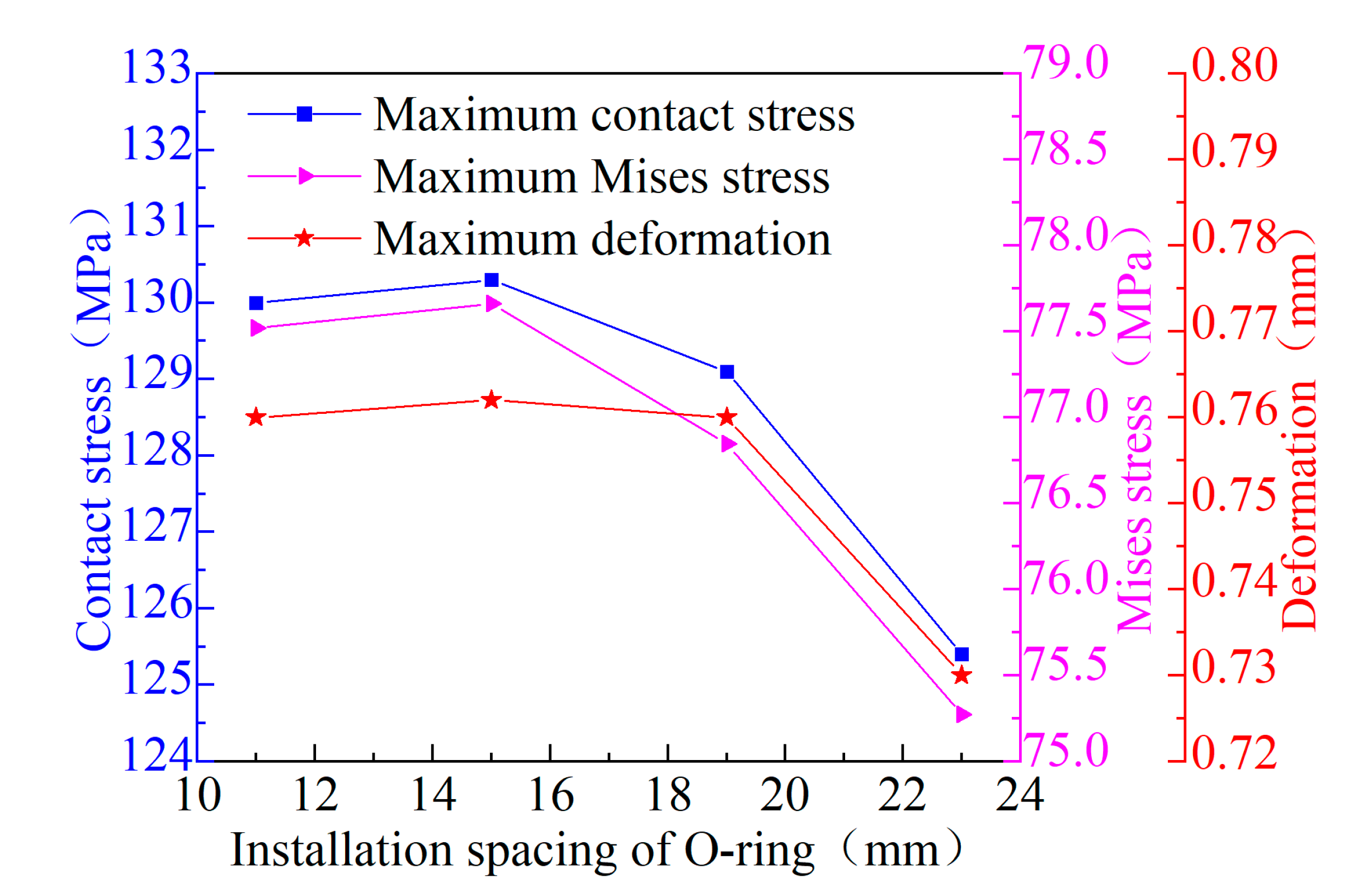
Figure 11.
(a) Stress peak distribution diagram of O-ring; (b) Deformation peak distribution diagram of O-ring; (c) Contact stress peak distribution diagram of O-ring.
Figure 11.
(a) Stress peak distribution diagram of O-ring; (b) Deformation peak distribution diagram of O-ring; (c) Contact stress peak distribution diagram of O-ring.

Figure 12.
(a) Stress peak distribution cloud map of the O-ring at E = 760 MPa; (b) Deformation peak distribution cloud map of the O-ring at E = 760 MPa; (c) Contact stress peak distribution cloud map of the O-ring at E = 760 MPa.
Figure 12.
(a) Stress peak distribution cloud map of the O-ring at E = 760 MPa; (b) Deformation peak distribution cloud map of the O-ring at E = 760 MPa; (c) Contact stress peak distribution cloud map of the O-ring at E = 760 MPa.
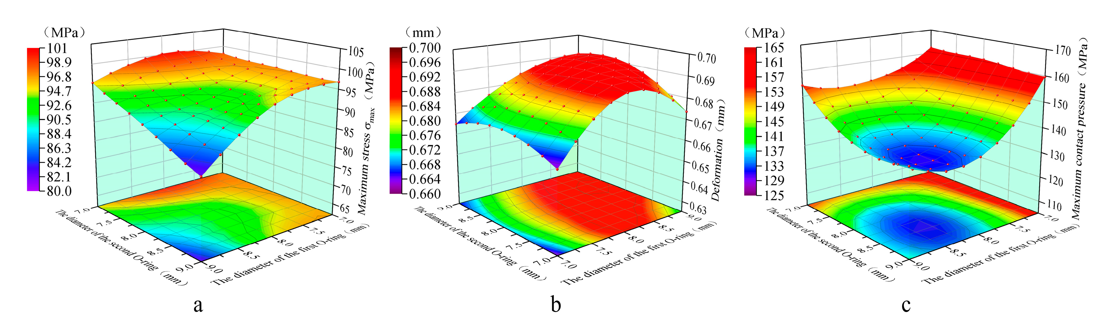
Figure 13.
(a) Stress peak distribution cloud map of the O-ring at E = 660 MPa; (b) Deformation peak distribution cloud map of the O-ring at E = 660 MPa; (c) Contact stress peak distribution cloud map of the O-ring at E = 660 MPa.
Figure 13.
(a) Stress peak distribution cloud map of the O-ring at E = 660 MPa; (b) Deformation peak distribution cloud map of the O-ring at E = 660 MPa; (c) Contact stress peak distribution cloud map of the O-ring at E = 660 MPa.
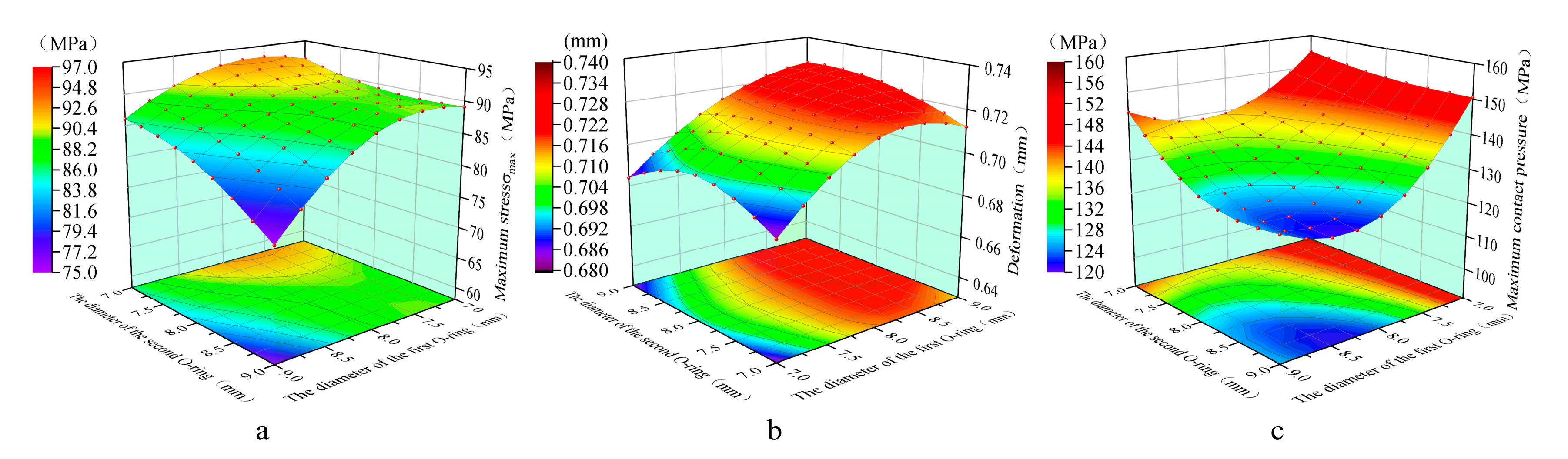
Figure 14.
(a) Stress peak distribution cloud map of the O-ring at E = 560 MPa; (b) Deformation peak distribution cloud map of the O-ring at E = 560 MPa; (c) Contact stress peak distribution cloud map of the O-ring at E = 560 MPa.
Figure 14.
(a) Stress peak distribution cloud map of the O-ring at E = 560 MPa; (b) Deformation peak distribution cloud map of the O-ring at E = 560 MPa; (c) Contact stress peak distribution cloud map of the O-ring at E = 560 MPa.

Table 1.
Main design dimensions of the sealing structure.
| Name | Unit (mm) |
|---|---|
| inner diameter of the inner cylinder | 373 |
| inner cylinder thickness | 6 |
| Thickness of carbon fibre winding layer | 15 |
| Metal valve seat bore diameter | 50 |
| Outer diameter of sleeve | 96 |
| O-ring diameter | 5-10 |
Table 2.
Performance parameters of bottle mouth sealing structure materials.
| Name | value |
|---|---|
| HDPE elastic modulus, E1 | 1080MPa |
| HDPE poisson ratio, μ1 | 0.4183 |
| Plastic inner cylinder density, ρ1 | 958.5 kg/m3 |
| PTFE density, ρ2 | 2.2 g/cm3 |
| PTFE elastic modulus, E2 | 560MPa-760MPa |
| PTFE poisson ratio, μ2 | 0.4532 |
| PTFE yield strength, σlim1 | 97MPa |
| Aluminium alloy pressure relief ring, ρ3 | 2770 kg/m3 |
| Pressure relief ring elastic modulus, E3 | 71GPa |
| Poisson’s ratio of pressure relief ring, μ3 | 0.33 |
| Pressure relief ring compressive strength limit, σlim2 | 280MPa |
| PEEK elastic modulus, E4 | 4.2GPa |
| PEEK density, ρ4 | 1.3 g/cm3 |
| PEEK Poisson ratio, μ4 | 0.42 |
| PEEK Yield strength limit, σslim | 125MPa |
Table 3.
Relationship between the number of grid cells.
| Grid size (mm) | Number of grids | Number of grid nodes |
|---|---|---|
| 3 | 138000 | 193000 |
| 2.5 | 142000 | 199000 |
| 2 | 150000 | 212000 |
| 1.5 | 172000 | 244000 |
| 1 | 276000 | 392000 |
| 0.5 | 465000 | 650000 |
Disclaimer/Publisher’s Note: The statements, opinions and data contained in all publications are solely those of the individual author(s) and contributor(s) and not of MDPI and/or the editor(s). MDPI and/or the editor(s) disclaim responsibility for any injury to people or property resulting from any ideas, methods, instructions or products referred to in the content. |
© 2025 by the authors. Licensee MDPI, Basel, Switzerland. This article is an open access article distributed under the terms and conditions of the Creative Commons Attribution (CC BY) license (http://creativecommons.org/licenses/by/4.0/).
Copyright: This open access article is published under a Creative Commons CC BY 4.0 license, which permit the free download, distribution, and reuse, provided that the author and preprint are cited in any reuse.


