
Submitted:
02 July 2025
Posted:
02 July 2025
You are already at the latest version
Abstract
The mechanical performance of natural fiber-reinforced polymer composites depends on fiber characteristics, matrix properties, and interfacial modifications. Although surface treatments such as polishing, coatings, and film lamination are commonly applied to enhance appearance, durability, or functionality, their effects on mechanical properties remain underexplored. This study investigates the influence of polypropylene (PP) and polyethylene terephthalate (PET) film lamination on the tensile behavior of wood fiber-reinforced polypropylene composites. Dumbbell-shaped specimens of neat PP and PP reinforced with 25 wt% wood fiber were fabricated via injection molding, then laminated with 0.1 mm PET or PP films using a plastic-compatible adhesive. Laminations were applied in four configurations: unlaminated (0S), single-sided lamination covering half the specimen length (1S-H), single-sided full-length lamination (1S-F), and double-sided full-length lamination (2S-F). PET film significantly improved tensile strength, with the 2S-F configuration yielding increases of 12% and 21% for neat PP and wood-filled PP, respectively. In contrast, PP film generally had minimal or negative effects, except in the 2S-F wood-filled case, which exhibited a 5% gain. Enhancements were attributed to PET’s superior stiffness and to surface homogenization, which reduced surface defects and improved stress distribution—effects supported by rule-of-mixtures predictions and morphological analysis. Surface roughness measurements and SEM confirmed smoother profiles and sealed surface voids, while fractographic evidence indicated that lamination mitigated crack initiation at specimen corners. These findings demonstrate that film lamination, particularly with PET, is an effective post-processing strategy for improving the mechanical integrity of wood-plastic composites.
Keywords:
wood plastic composites
; film lamination
; injection molding
; tensile test
1. Introduction
Eco-friendly composites reinforced with natural fibers such as wood flour (WF), hemp, jute, and kenaf, in combination with recyclable thermoplastics like polypropylene (PP), polyvinyl chloride (PVC), polystyrene (PS), and polyethylene (PE), have emerged as promising alternatives to conventional synthetic composites, particularly glass fiber-reinforced polymers, which pose significant environmental challenges due to their non-biodegradability and high embodied energy [1,2,3]. These natural fiber-reinforced polymer composites (NFRPCs) offer several advantages, including low density, renewability, cost-effectiveness, high specific strength, and reduced energy consumption during processing [4,5]. Despite these merits, their widespread adoption is constrained by several inherent limitations. Chief among these is the hydrophilic nature of lignocellulosic fibers, which impairs interfacial adhesion with hydrophobic polymer matrices, resulting in poor stress transfer and suboptimal mechanical performance. Furthermore, their hygroscopic behavior leads to moisture absorption even within the matrix, causing dimensional instability, swelling, and microcracking under cyclic environmental exposure. These effects not only compromise structural integrity but also reduce long-term durability. In addition, natural fibers are susceptible to microbial degradation and fungal growth in humid conditions, further limiting their service life. Variability in fiber morphology and properties, arising from differences in plant species, cultivation conditions, and processing methods, also contributes to inconsistency in composite performance.
To overcome the inherent limitations of natural fiber-reinforced composites, extensive research has focused on enhancing their mechanical performance, moisture resistance, and long-term durability through various material and processing innovations. One of the most widely adopted and effective strategies is the incorporation of compatibilizing agents, notably maleic anhydride-grafted polypropylene (MAPP), which promotes covalent or secondary bonding between the hydrophilic fiber surfaces and hydrophobic polymer matrices, thereby improving interfacial adhesion and stress transfer [6,7,8,9,10,11]. Complementary to this approach, fiber surface modification techniques—including alkali treatment, silanization, acetylation, and enzymatic functionalization—serve to reduce fiber hydrophilicity, increase surface roughness, and introduce reactive functional groups, all of which contribute to enhanced fiber-matrix compatibility [12,13,14,15,16,17,18,19,20,21,22]. The use of regenerated cellulose fibers, such as Cordenka, has also gained traction due to their consistent morphology and improved interfacial affinity with thermoplastics [23,24,25,26,27]. In addition, advanced fiber pre-treatment processes like the Multi-Pin Assisted Resin Impregnation (M-PaRI) technique have demonstrated the ability to increase fiber hydrophobicity prior to compounding, thereby promoting superior fiber-matrix integration and composite performance [23,28]. Modifying the polymer matrix itself—through reactive extrusion or blending with more polar polymers—offers another pathway to reinforce interfacial interactions [21,29,30,31,32,33,34]. Furthermore, composite-level surface treatments such as lamination, plasma activation, and functional coatings have been employed to impart additional benefits, including improved flame retardancy via insulating barrier formation, enhanced dimensional stability by mitigating moisture uptake, and increased resistance to microbial attack [35,36,37,38,39,40,41,42,43,44,44].
To further clarify the current state of research, several notable studies may be highlighted, each addressing key aspects of material selection, fiber treatment, and processing techniques to improve composite performance. For instance, Yang et al. investigated the combined use of ammonium polyphosphate (APP) and self-assembled montmorillonite/layered double hydroxide (MMT/LDH) nanosheets as a flame-retardant system for wood plastic composites (WPCs) [45]. Recognizing the limitations associated with high APP loading—namely, increased smoke emission and compromised mechanical strength—they introduced a two-dimensional hybrid additive to counteract these drawbacks. The incorporation of MMT/LDH nanosheets, known for their catalytic charring and smoke-suppressing capabilities, enhanced the dispersion and synergistic action of APP. This approach significantly reduced peak heat release rate (pHRR), total heat release (THR), and total smoke production (TSP) by 35.6%, 21.0%, and 13.8%, respectively, compared to neat WPCs. Importantly, the modified composites also exhibited a modest improvement in mechanical properties, underscoring the potential of this phosphorus–nitrogen–inorganic hybrid system for producing safer, structurally reliable flame-retardant WPCs.
Widiastuti et al. examined the influence of polymer matrix type, wood species, and fabrication method on the mechanical and physical performance of wood plastic composites (WPCs) developed using wood waste and recycled polypropylene [46]. Their study compared composites fabricated from virgin and recycled polypropylene (v-PP and r-PP) matrices combined with teakwood or ironwood flour, using both compression moulding (CM) and injection moulding (IM) techniques. Results from tensile testing revealed that specimens produced via injection moulding exhibited notably higher tensile strength and lower water absorption than their compression-moulded counterparts. Among IM samples, composites reinforced with teakwood showed better mechanical performance than those incorporating ironwood. Additionally, virgin polypropylene matrices generally outperformed recycled ones in tensile strength, especially under CM processing. Water immersion tests in both freshwater and seawater further demonstrated that moisture uptake was significantly affected by both the type of polymer and the processing route. These findings highlight the critical roles of material selection and processing method in optimizing the structural integrity and durability of sustainable WPCs.
Pokhrel et al. explored the viability of using wood pellets as an alternative lignocellulosic filler in polypropylene-based wood plastic composites, aiming to reduce transportation costs associated with raw material supply [47]. Their study compared WPCs fabricated from conventional wood flour and ground wood pellets derived from four hardwood and softwood species, with and without the incorporation of maleic anhydride polypropylene (MAPP) as a coupling agent. Microscopic analysis revealed a more uniform dispersion of particles in the polymer matrix when wood pellets were used, although tensile strength, modulus, and impact resistance were slightly lower compared to the composites reinforced with wood flour. Flexural performance showed mixed results: pellet-based composites exhibited higher strength in the absence of MAPP, but slightly lower values when MAPP was included. Nonetheless, most mechanical property differences remained within a 0.5–10% range, and statistical evaluation confirmed that the differences were not significant. These results suggest that wood pellets can be a practical substitute for wood flour in WPC manufacturing, offering comparable mechanical performance with the added advantage of reduced transportation expenses.
Zárate-Pérez et al. examined how different coupling agents influence the mechanical and thermal performance of polypropylene composites reinforced with wood flour, aiming to overcome the inherent incompatibility between hydrophilic fibers and the hydrophobic polymer matrix [48]. Their investigation compared graft and masterbatch-type compatibilizers within a melt intercalation processing route. The study found that grafted agents promoted more effective molecular interaction with the matrix, resulting in improved elastic modulus—rising by approximately 82% compared to neat PP—though tensile strength gains were limited due to inadequate interfacial adhesion. Despite the mechanical limitations, wood flour enhanced the crystallinity of the composites, acting as a nucleating agent and thereby influencing thermal behavior. The processing route also played a significant role: melt blending encouraged molecular alignment, whereas injection molding appeared to erase the material’s previous thermal history. Morphological analysis revealed that weak fiber-matrix adhesion hindered stress transfer, contributing to reduced ductility, with failure occurring soon after yielding at strains of just 2–4%. Overall, the findings emphasized that while stiffness and thermal properties can be enhanced through appropriate compatibilization and processing, tensile strength remains constrained by interfacial bonding limitations.
Luo et al. proposed a crystallization-based strategy to enhance the toughness of polypropylene composites filled with wood flour, addressing a common limitation of such materials [49]. Their approach involved incorporating self-assembling -nucleating agents into the PP matrix, specifically comparing the performance of an aryl amide compound (TMB5) and a rare-earth-based complex (WBG II) at various concentrations. Both agents proved highly efficient in promoting -phase crystallization, with the -phase fraction (k) reaching as high as 0.8 at a minimal loading of 0.05 wt%. This modification refined the crystalline structure by reducing spherulite size and elevating crystallization temperature, thereby accelerating solidification. The altered crystalline morphology led to marked gains in toughness; with 0.3 wt% of either additive, the notched impact strength rose by about 28% and the elongation at break improved by roughly 40%. While the WBG-modified composites exhibited a slightly higher -content, TMB yielded a finer crystalline network, contributing to superior tensile strength and stiffness. This study underscores the potential of nucleation-induced crystallinity control as an effective means to simultaneously enhance both the ductility and structural integrity of wood-filled thermoplastic composites.
Zhu et al. developed a fully bio-based intumescent flame retardant, termed VR-PA, to improve the fire safety of wood flour/polypropylene (WFPP) composites [50]. VR-PA was synthesized through a Schiff base reaction between vanillin and l-arginine, followed by the introduction of phytic acid via electrostatic interaction. When incorporated into WFPP at 20 wt%, this novel flame retardant significantly enhanced the composite’s fire performance, raising the limiting oxygen index (LOI) to 28.2% and reducing both the peak heat release rate and total heat release by 35.4% and 20.6%, respectively. A 15 wt% loading also yielded a pronounced 42.1% reduction in total smoke production. These improvements are attributed to VR-PA’s dual action: in the gas phase, it captures free radicals during combustion, and in the condensed phase, it promotes the formation of a robust, expanded char layer. The findings demonstrate that VR-PA offers an environmentally friendly strategy for enhancing the flame retardancy and smoke suppression of WFPP composites without compromising sustainability.
Gairola et al. investigated the use of boron-based cross-linking to enhance the flame retardancy of natural fiber-reinforced polypropylene composites [51]. In this study, jute-sisal fabrics were modified using borax and subsequently integrated into a PP matrix to fabricate fire-retardant biocomposites. The borax pretreatment significantly elevated flame resistance, reflected in a 25.28% rise in limiting oxygen index (LOI), a 60.16% reduction in peak heat release rate (pHRR), and a 3.59% drop in average heat release rate (av-HRR) relative to untreated counterparts. When used as reinforcement in PP, the borax-treated fibers yielded composites with markedly improved thermal and flammability properties, including a 22.01% gain in LOI, and reductions of 22.29% and 22.23% in pHRR and av-HRR, respectively. Additional enhancements were observed in dimensional thermal stability, evidenced by favorable shifts in heat deflection temperature and thermal expansion coefficients. Post-combustion residue analysis revealed that the treated fibers formed a compact char structure, which likely acted as an effective thermal barrier, limiting heat transfer and delaying material degradation during combustion.
Ondiek et al. [35] examined the mechanical response of wood–plastic composites (WPCs) subjected to plasma surface modification followed by nanocellulose-based surface coating. The composites were fabricated via injection molding, employing polypropylene (PP) as the thermoplastic matrix and short wood fibers (WF) as reinforcement at 0 wt%, 25 wt% (WP25), and 50 wt% (WP50) loadings, conforming to JIS K7139-A32 standards. Plasma irradiation was first applied to the tensile specimens to activate the surface, followed by immersion in an acrylic resin containing uniformly dispersed TEMPO-oxidized cellulose nanofibers (CNFs). Surface topography analysis revealed that plasma treatment increased surface roughness, whereas subsequent coating significantly reduced it—by nearly 50% relative to untreated samples. In terms of mechanical behavior, the combination of plasma and CNF-based surface coating led to moderate increases in tensile strength: 5.4–7.1% for neat PP, 3.5–3.7% for WP25, and 3.0–3.6% for WP50, though these gains were accompanied by slight reductions in fracture strain. The coated specimens consistently outperformed their uncoated counterparts in tensile strength, emphasizing that enhanced interfacial bonding between the coating and substrate—rather than surface roughness alone—played a more decisive role in mechanical reinforcement. These results underscore the potential of surface-engineering strategies to improve the structural integrity of WPCs.
The foregoing review highlights a representative selection of studies that collectively reflect the sustained and multifaceted efforts to enhance the performance of wood–plastic composites (WPCs). Across the literature, the predominant objective has been to optimize WPCs such that their intrinsic advantages—such as low cost, renewability, and environmental compatibility—are preserved, while their inherent drawbacks, particularly in comparison to synthetic fiber-reinforced composites like carbon, glass, or aramid, are systematically mitigated. Despite this considerable progress, critical knowledge gaps remain. In particular, the role of surface treatment techniques—such as lamination or coating—on the mechanical performance of WPCs has received minimal attention. Surface treatments have traditionally been employed to serve ancillary functions, including moisture resistance, microbial inhibition, thermal and electrical functionality, or improved visual appearance. However, their potential as a route to mechanically reinforce WPCs has been largely overlooked. This study, therefore, seeks to address this gap by investigating the influence of thin film lamination—using polypropylene (PP) and polyethylene terephthalate (PET) films—on the mechanical properties of WPCs.
2. Materials and Methods
2.1. Raw Materials
Wood flour masterbatch (Celbrid N, comprising 68.1 wt% wood flour (WF), 29.2 wt% polypropylene (PP), and 2.7 wt% maleic anhydride-grafted polypropylene (MAPP); Toklas Co., Ltd.) was used as the reinforcement material. Pelletized PP (J108M; Prime Polymer Co., Ltd.) served as the matrix resin. MAPP (Kayabrid 006PP; Kayaku Akzo Co., Ltd.), added at 2 wt% of the base material, was used as a compatibilizer to enhance interfacial adhesion. For surface lamination of the specimens, 0.1 mm PP film (735H10; King Jim Co., Ltd., Tokyo, Japan) and 0.1 mm PET film (HBF-321BN; Iris Ohyama Inc., Tokyo, Japan) were applied using a plastic adhesive (Cemedine PPX CA-522; Cemedine Co., Ltd., Tokyo, Japan).
2.2. Preparation of Neat PP and WF/PP Composite Specimens
WF/PP composite specimens containing 25 wt% wood fiber (WF) were prepared by melt compounding polypropylene (PP) pellets, wood flour masterbatch (Celbrid N), and maleic anhydride-grafted polypropylene (MAPP; Kayabrid 006PP) in a kneading machine (DS0.5-3MHB-E, Satake Chemical Machinery Industry Co., Ltd.) at 210°C for 10 minutes to ensure homogeneous dispersion of the constituents. The formulation was calculated based on the known composition of the masterbatch—comprising 68.1 wt% WF, 29.2 wt% PP, and 2.7 wt% MAPP—so that the resulting composite contained exactly 25 wt% WF in the PP matrix, taking into account the PP and MAPP contributed by the masterbatch. The compounded material was then cooled and pelletized into granules approximately 2 mm in length using a pulverizing machine (U-280, ZI-420 type, Horai Co., Ltd.).
Prior to injection molding, silicone spray (Kure Industry Co., Ltd., Japan) was applied to the mold surface of the injection molding machine (Babyplast 6/10P, Rambaldi + Co. I. T. Srl) to reduce friction and facilitate easy removal of the molded specimens. The granules were then injection molded into dumbbell-shaped specimens. After molding, the specimens were allowed to cool at room temperature for 24 hours. Subsequently, silicone remover (Musashi Holt Corporation, Japan) was used to clean the specimen surfaces and eliminate any residual silicone spray prior to further processing such as surface lamination. Neat PP specimens were prepared following the same procedure, using only PP pellets (PP J108M; Prime Polymer Co., Ltd.), and processed under identical injection molding and cooling conditions. The dumbbell-shaped specimens were prepared in accordance with JIS K7139-A32 specifications. A schematic diagram showing the dimensions of the A32-type specimen is presented in Figure 1 [35].
2.3. Preparation of 0.1-mm PP and PET Film Specimens
PP and PET films, each with a thickness of 0.1 mm, were manually cut into rectangular strips measuring 75 mm in length and 5 mm in width using a sharp hand-held cutting blade. To facilitate secure gripping during tensile testing and to reduce the likelihood of slippage or edge failure, rigid plastic plates (gripping plastics) were prepared from a 2 mm thick plastic sheet and cut into 10 mm × 5 mm pieces. These gripping plastics were bonded to both the top and bottom surfaces at each end of the film strips. To ensure effective adhesion, a primer (Cemedine PPX Primer; Cemedine Co., Ltd., Tokyo, Japan) was first applied to the bonding regions of the film strips. Within 30 seconds of applying the primer, a cyanoacrylate-based adhesive designed for polyolefins (Cemedine PPX CA-522; Cemedine Co., Ltd., Tokyo, Japan) was applied, and the gripping plastics were immediately positioned. Gentle finger pressure was used to maintain full surface contact and proper alignment. The bonded specimens were then left at room temperature for 24 hours to allow complete curing. A dimensioned schematic of the prepared film specimen is shown in Fig. 2.
2.4. Film Lamination of Tensile Specimens
To prepare the laminated dumbbell specimens, the same PP and PET films described in the previous section—each with a thickness of 0.1 mm—were cut into narrow strips 5 mm in width, corresponding to the gauge section of the tensile specimens. Likewise, the same primer used for attaching the gripping plastics in the film specimens was applied to the surface of both neat PP and 25 wt% wood fiber-reinforced PP composite specimens at room temperature. Within 30 seconds of primer application, the previously introduced cyanoacrylate-based adhesive was applied to the primed surface. The film strips were then carefully positioned and laminated onto the adhesive-coated surfaces by pressing manually with finger pressure to ensure intimate contact.
Lamination was performed in four distinct configurations: no lamination (0S), full-surface lamination on one side (1S-F), full-surface lamination on both sides (2S-F), and partial lamination on one side extending from one end to the specimen midspan (1S-H). In all laminated configurations, the film extended continuously across the full specimen length, including the gripping sections—except in (1S-H), where it covered only half the length. A schematic illustration of the lamination configurations is shown in Figure 3. All laminated specimens were left to cure under ambient conditions for 24 hours to ensure complete bonding. No external pressure or thermal treatment was applied during the curing period
Representative images of the film and tensile specimens are provided in Figure 4 and Figure 5, respectively. To avoid redundancy, only PET film specimens are shown for the film samples, and PP film-laminated specimens are shown for the dumbbell tensile specimens. Among the various lamination configurations, only specimens laminated in the 1S-F configuration are presented, as their external appearance is representative of all other laminated types.
2.5. Surface Roughness Measurements
Surface roughness was measured using a surface roughness and contour measuring machine (SURFCOM NEX 031/041 DX2/SD2, Tokyo Seimitsu, Japan). For the unlaminated neat PP and WF/PP composite specimens, measurements were taken in both the longitudinal and transverse directions to comprehensively assess surface topography. The analysis focused specifically on the bonding surfaces, where adhesive would typically be applied. In contrast, for the 0.1 mm-thick PP and PET laminating films, measurements were conducted in randomly selected directions. This approach was appropriate given that the films were manufactured via biaxial processing, resulting in isotropic surface characteristics that obviate the need for directional constraints. Surface roughness measurements were not performed directly on the laminated specimens. Instead, the surface profiles of the laminating films were considered representative of the surface condition of the laminated composites. For each surface, measurements were taken at three randomly selected locations, and the average surface roughness () was calculated. Scans were performed over a length of 4.0 mm at a speed of 0.150 mm/s. A least-squares line was used for form removal, and a Gaussian filter with a cutoff wavelength () of 0.8 mm was applied during data processing.
2.6. Scanning Electron Microscopy (SEM)
The surface morphologies of both unlaminated and laminated 25 wt% WF/PP composite specimens were examined using a field emission scanning electron microscope (FE-SEM; JSM-7000F, Japan Electron Optics Laboratory Co., Ltd., Akishima, Tokyo, Japan). In addition, fractured surfaces obtained after tensile testing were observed to evaluate interfacial characteristics and fracture mechanisms. Prior to imaging, all samples were sputter-coated with a thin layer of platinum to enhance surface conductivity and minimize charging effects. SEM observations were carried out at an accelerating voltage of 15.0 kV. Magnification levels were varied depending on the morphological features of interest to enable both general surface assessment and detailed interfacial analysis.
2.7. Mechanical Testing
Tensile tests were performed on both laminated and unlaminated injection-molded specimens, as well as on the laminating films (PP and PET), to evaluate their mechanical properties. All tests were conducted using an LSC-1/30D universal testing machine (JT Tosi) equipped with a 1 kN load cell, operated at room temperature (25 °C) and a constant crosshead speed of 10 mm/min. For each material and test condition, five to seven specimens were evaluated. The load–displacement data were converted to engineering stress–strain curves using established formulations, as detailed in standard references [52,53]:
where is the engineering tensile stress (MPa), P is the applied load (N), A is the original cross-sectional area of the specimen (), is the engineering tensile strain (dimensionless), is the elongation (mm), and is the original gauge length (mm).
3. Results & Discussion
3.1. Surface Roughness of Unlaminated Specimens and Laminating Films
Table 1 presents the average surface roughness () values for the unlaminated neat PP and 25 wt% WF/PP composite specimens, while Table 2 presents the surface roughness values for the 0.1 mm thick PP and PET laminating films. For all materials, the coefficient of variation (CV)—expressed as a percentage of the mean—is shown in parentheses to indicate measurement variability. Representative surface roughness profiles for the specimens and films are illustrated in Figure 6 and Figure 7, respectively.
As shown in Table 1 and Figure 6, the surface roughness () in the transverse direction was substantially higher than in the longitudinal direction for both unlaminated neat PP and 25 wt% WF/PP specimens. Specifically, the transverse roughness was approximately 13 times greater for neat PP and 2.8 times greater for 25 wt% WF/PP compared to their respective longitudinal values. In the longitudinal direction, neat PP exhibited lower roughness than 25 wt% WF/PP, whereas in the transverse direction, the opposite trend was observed. This pronounced increase in transverse roughness is likely due to scratches and flaws on the mold die surface, which were replicated on the specimen surface during fabrication. Notably, neat PP specimens appeared more sensitive to these surface imperfections.
For the 0.1 mm PP and PET films (see Table 2 and Figure 7), surface roughness values differed significantly from those of the neat PP and 25 wt% WF/PP specimens. The films exhibited low and uniform surface roughness, with average values of 0.10 and 0.03 µm for the PP and PET films, respectively. In contrast, the neat PP and 25 wt% WF/PP specimens showed higher roughness values of 1.56 and 0.86 µm, respectively, in the longitudinal direction—the direction with maximum surface roughness. The low roughness and small coefficients of variation observed in the films confirm their homogeneous surface texture, which contributed to the smoothing and homogenization of the composite surface upon lamination. These results demonstrate that both PP and PET films are effective laminating materials for reducing surface roughness and masking surface defects in PP and WF/PP composites.
A comparison of the two laminating films (PP and PET) based on Table 2 and Figure 7 shows that the 0.1 mm PET film exhibits a smoother surface than the 0.1 mm PP film. The PET film recorded a lower average value of 0.03 µm, compared to 0.10 µm for the PP film. In addition, the surface profile of the PET film (Figure 7b) appears finer and more uniform than that of the PP film (Figure 7a), indicating a higher degree of surface homogeneity. Although both films effectively reduced the surface roughness of the neat PP and WF/PP specimens when applied as laminating layers, the PET film proved more effective in achieving a smoother and more uniform laminated surface. This superior performance can be attributed to the intrinsic smoothness and finer microtexture of the PET film, which likely enhanced its ability to conform to and mask surface irregularities in the substrate during lamination.
3.2. SEM Surface Morphology of WP Composites
Figure 8 presents scanning electron micrographs of 25 wt% WP composites, comparing surface morphologies of unlaminated samples with those laminated using a 0.1 mm PET film. Each image includes a scale bar to provide accurate dimensional context. The unlaminated surfaces (Figure 8a and b) exhibit a visibly rough morphology. At increased magnification (Figure 8b), distinct surface irregularities become apparent, including a prominent void partially bridged by embedded wood fibers within the PP matrix. This feature suggests limited fiber–matrix interfacial bonding; however, the void remains only partially filled, likely due to inadequate wetting or insufficient fiber dispersion during processing. In contrast, the laminated specimens (Figure 8c and d) display a markedly smoother and more continuous surface profile. Even under higher magnification (Figure 8d), the surface maintains a uniform texture with minimal observable defects.
These findings affirm the effectiveness of PET film lamination in mitigating surface irregularities, sealing surface voids, and significantly enhancing the overall surface homogeneity of WF/PP composites. This observed improvement in surface morphology aligns with reports on WPCs treated with nanodispersed cellulose nanofiber (CNF)-reinforced acrylic resin coatings [35], where both plain and TEMPO-oxidized CNFs also contributed to improved surface homogeneity. However, the degree of surface refinement achieved through PET film lamination in the present study appears to surpass that obtained with these CNF-based treatments. This suggests that the continuous physical barrier provided by film lamination offers a more comprehensive and robust approach for optimizing surface characteristics in WF/PP composites compared to dispersed nanofiller coatings.
3.3. Tensile Properties of Unlaminated and Laminated PP and WF/PP Specimens and Their Laminating Films
Table 3 details the tensile properties of 0.1 mm PP and PET films, while Table 4 presents those of neat PP and 25 wt% WF/PP composites under their various lamination configurations (0S, 1S-H, 1S-F, and 2S-F), with coefficients of variation shown in parentheses beside the respective values. Figure 9 illustrates representative tensile stress–strain curves for the films, and Figure 10 depicts the stress–strain behavior of neat PP and WF/PP composites under these different lamination conditions. Additionally, a Lamination Strength Ratio (LSR) column is provided in Table 4. This ratio, calculated as , represents the tensile strength of each laminated specimen () relative to its unlaminated reference (). LSR values greater than one indicate enhanced tensile strength due to lamination.
The tensile properties of the 0.1 mm PET and PP films (Figure 9) reveal a marked contrast, underscoring their differing suitability for use as surface laminates in composite structures. The PET film exhibits a tensile strength of 113.2 MPa—approximately 3.8 times greater than the 29.5 MPa recorded for the PP film—attributable to the inherently higher stiffness and molecular orientation of PET. While both films display large fracture strains, the PP film is more ductile, with strains exceeding 100% of the original gauge length, compared to an average of 88.1% for PET. These results demonstrate that PET offers superior strength, whereas PP contributes more to flexibility. Moreover, the PET film undergoes significant strain hardening after yielding, with its maximum strength approximately 42% higher than the yield point. In contrast, the PP film exhibits strain softening, characterized by a reduction in stress after peak strength, followed by stable plastic deformation. These contrasting behaviors are critical in evaluating their performance as laminating materials. The strain hardening of PET enhances its load-bearing capability and resistance to plastic deformation under tensile loading, making it more effective in reinforcing the structural integrity of laminated composites. Conversely, the higher ductility of PP may offer advantages in applications requiring flexibility but contributes less to overall stiffness and strength. Accordingly, PET is the more suitable choice for applications where mechanical reinforcement of the substrate is a primary requirement.
In the case of neat PP specimens, lamination with the 0.1 mm PP film resulted in a reduction in tensile strength, as indicated by LSR values below unity. Specifically, the 1S-F configuration exhibited a 4.0% decrease in tensile strength, while the 2S-F configuration showed a more pronounced 6.4% reduction compared to the unlaminated PP specimen. This decline is primarily attributed to the lower tensile strength of the laminated PP film relative to the bulk PP substrate, which introduced a mechanically weaker surface layer and consequently diminished the overall load-bearing capacity of the specimens. This interpretation is further supported by the observed trend: the reduction in tensile strength correlates with the extent of laminated surface area, as evidenced by the progressive decline from the 0S to the 1S-F and 2S-F configurations. Thus, although PP film lamination may offer certain surface-related advantages—such as homogenization, void sealing, and improved surface smoothness—the overriding influence of its low intrinsic strength ultimately led to a net reduction in tensile performance.
Another contributing factor may be the high sensitivity of polypropylene to stress concentrations, which are often introduced by notches or microcracks that can form on the film surface due to firm adhesive bonding during lamination. Given that PP–PP adhesion is relatively strong compared to bonding with dissimilar materials, any initial crack in the adhesive layer can easily propagate through the film and into the underlying substrate. Because the adhesive bond between the film and the specimen is strong, delamination does not occur, allowing the crack to transfer directly to the specimen surface. This mechanism likely contributes to the observed reduction in tensile strength. This behavior is particularly evident in the 2S-F configuration, which unexpectedly exhibits a markedly low fracture strain. It is inferred that double-sided lamination imposes significant constraints on the specimen during tensile loading. In the absence of debonding, as previously discussed, cracks originating from the film or adhesive interface are rapidly transferred to the substrate, resulting in premature rupture and fracture. This explains the anomalous fracture behavior observed in the 2S-F configuration.
In contrast, the other configurations—namely 0S and 1S-F—exhibited normal ductile behavior, with fracture strains exceeding 200% of the original gauge length. Such extensive elongation is consistent with the well-known ductility of polypropylene and aligns with expectations for unreinforced or single-laminated PP specimens. The 1S-F configuration, in particular, retains an unlaminated surface, which allows greater deformation freedom on one side. This reduces the constraining effect associated with film bonding, thereby mitigating premature crack transfer and enabling fracture strain behavior comparable to that of the unlaminated specimen.
The lamination of neat PP specimens with the 0.1 mm PET film, however, resulted in improved tensile strength, as reflected by LSR values exceeding one. The tensile strength increased progressively with greater surface coverage—by 1.9% for the 1S-H configuration, 2.9% for 1S-F, and 12.3% for 2S-F—relative to the unlaminated specimen. This positive correlation is primarily attributed to the superior intrinsic strength and stiffness of PET, which imparts a reinforcing effect akin to that of a composite layer when firmly bonded to the PP substrate. Further evidence is provided by surface roughness measurements and SEM observations (Figure 7 and Figure 8), which indicate that PET lamination effectively sealed surface voids and irregularities, producing a more uniform and defect-free surface. This morphological improvement likely reduced stress concentrations and delayed the onset of crack initiation under tensile loading. The most significant enhancement was observed in the 2S-F configuration, which benefited from full surface coverage on both sides—minimizing the number of flaw sites and maximizing structural reinforcement, thereby yielding the highest tensile strength improvement among the tested configurations. Additionally, although the adhesive bond between the PET film laminate and the PP substrate is relatively weaker than that observed with PP film lamination, the reinforcement provided by the PET film’s superior intrinsic strength appears to outweigh the drawbacks associated with the weaker interfacial bonding. This indicates that the mechanical advantage conferred by the PET layer is primarily governed by its own strength and stiffness, rather than by adhesive performance alone.
With respect to fracture strain, all PET-laminated configurations—except for 1S-H—exhibited pronounced ductility, with elongation exceeding 200% prior to failure. This behavior is consistent with the inherent ductility of polypropylene, as previously discussed. In contrast, the 1S-H configuration showed a markedly reduced fracture strain. This anomaly is attributed to stress concentration localized at the specimen midspan, where the PET film coverage terminates. The abrupt interface between the laminated and unlaminated regions likely acted as a stress riser, initiating crack formation at the substrate surface. The crack then propagated rapidly through the specimen, leading to premature rupture. This explanation is supported by the observation that, in all tested specimens within the 1S-H configuration, fracture consistently occurred at the midspan—precisely at the transition point between the bonded and unbonded regions.
For the 25 wt% WF/PP composite specimens, lamination with the PP film exhibited a distinct behavior compared to neat PP. Under the 1S-F configuration, tensile strength remained essentially unchanged, as reflected by LSR value of 1.00. However, the 2S-F configuration showed a significant increase of 5.0% in tensile strength relative to the unlaminated composite. This contrasts with the trend observed in neat PP specimens, where lamination with the same PP film consistently reduced tensile strength across all configurations. This difference suggests that, despite the intrinsically low tensile strength of the PP film, its lamination on the rougher surface of the WF/PP composite produced a net positive effect. The presence of wood fibers inherently increases surface roughness and introduces interfacial voids or micro-defects during molding. When laminated with PP film, these surface irregularities were effectively smoothed and sealed, resulting in enhanced surface homogeneity. This likely reduced stress concentration sites and delayed crack initiation under tensile loading.
Moreover, although the lamination introduces a relatively weaker surface layer and restricts local deformation due to the strong but brittle adhesive bond, these drawbacks appear to be outweighed in the case of WF/PP composites by the reduction in surface flaws and improved load distribution at the interface. Especially in the 2S-F configuration, where both surfaces are covered, the cumulative effect of void sealing and stress mitigation becomes more pronounced, resulting in a net gain in tensile performance. These results underscore that surface modification through PP film lamination can be more beneficial for composite materials—where stress concentration is a greater concern—than for homogeneous polymers.
Regarding the fracture strains of the 25 wt% WF/PP specimens, film lamination generally led to increased ductility across all configurations, as evidenced by higher fracture strains compared to the unlaminated specimen (Table 4, Figure 10). This enhancement is attributed to the synergistic interaction between the ductile laminating films and the brittle WF/PP substrate, whereby the films absorbed part of the applied strain and redistributed stress more uniformly, effectively delaying fracture initiation. An exception was observed in the 1S-H configuration, which exhibited a noticeably reduced fracture strain. As discussed earlier in the case of neat PP specimens laminated with PET film, this reduction is likely due to asymmetric surface coverage—specifically, the film terminating near the specimen’s midspan—creating a localized stress concentration that served as a crack initiation site. The consistent midspan fracture location observed in this configuration supports this interpretation.
In summary, the results demonstrate that film lamination—particularly with PET—can significantly enhance the tensile strength of both PP and WF/PP specimens, with improvements strongly influenced by the film’s mechanical properties, bonding effectiveness, and surface coverage. Notably, PP film, despite its lower intrinsic strength, offered modest benefits for WF/PP composites by mitigating surface flaws that act as stress concentrators.
3.4. Fractography of WF/PP Composites after Tensile Testing
Figure 11 presents the fracture morphology of 25 wt% WF/PP composites after tensile testing. Based on the SEM micrographs, there was no observable evidence of macroscale fiber pull-out or interfacial debonding on the fracture surfaces, suggesting relatively strong interfacial adhesion between the wood fibers and the polypropylene matrix. Visual inspection of the fractured surfaces revealed two distinct regions that could be differentiated only by color: a smaller, whitened area and a larger, brown region. However, differences in surface texture were not detectable by the naked eye. Upon examination with a stereoscopic microscope, the larger brown region appeared rougher and more topographically irregular, whereas the smaller white region appeared comparatively smoother. These morphological differences were further confirmed by SEM imaging, which—despite not capturing color—clearly revealed two distinct fracture surface textures: a rough, bumpy region occupying a larger portion of the surface, and a smoother region covering a smaller area. To facilitate interpretation, the boundaries between these regions have been clearly demarcated and labeled in the SEM micrographs shown in Figure 11a–c.
This fracture pattern—comprising a larger rough, brown region and a smaller, smoother, whitened region—is consistent with the findings of Nordin et al.[54], who observed the reverse morphology under fatigue loading conditions. The whitened zone is indicative of polypropylene fibrillation, as suggested by its characteristic appearance and previously confirmed by Nordin et al.[54] through high-magnification SEM imaging. In addition, a distinct flat region was consistently observed near the corner edges of the fracture surface, located exclusively within the whitened area across all specimen configurations—unlaminated, PP-laminated, and PET-laminated—as illustrated in Figure 11.
In the context of fracture mechanics, crack propagation is broadly classified into two regimes: stable and unstable. In stable crack growth, the crack advances gradually under increasing load, while in unstable crack growth, rapid and catastrophic failure occurs once a critical crack length is reached [53,55]. Based on the morphology and location of the distinct regions, it is inferred that the whitened area corresponds to the zone of stable crack growth, and the brown, rough region represents the zone of unstable crack propagation. The flat feature within the whitened region is considered the likely site of crack initiation, from which the fracture subsequently propagated across the cross-section of the specimen. As previously noted, Nordin et al. [54] reported a dominant white fibrillated region and a relatively smaller brown area in fatigue-tested specimens. This discrepancy is attributed to the nature of loading: fatigue failure occurs at lower stress amplitudes but over longer durations, allowing cracks to propagate extensively before final failure. In contrast, tensile failure, as in the present study, occurs under higher stress levels where the critical crack length is reached more rapidly, resulting in a comparatively smaller stable fracture zone and a more extensive unstable region.
To assess the effect of film lamination on the suppression of fracture initiation, it is essential to consider the proportion of the specimen’s surface area covered by the laminate. Given that all specimens share an identical gauge length, the analysis can be normalized by considering a unit gauge length and focusing on the cross-sectional perimeter. For a specimen measuring 5 mm in width and 2 mm in thickness, the cross-sectional perimeter is 14 mm. The lamination film, also 5 mm wide, is applied to the broader (5 mm) surfaces of the specimen. Based on this configuration, the fraction of the perimeter covered by the laminate corresponds to approximately 10/14 for double-sided full-length lamination (2S-F), 5/14 for single-sided full-length lamination (1S-F), and 2.5/14 for single-sided half-length lamination (1S-H).
Among these configurations, 2S-F provides the most extensive surface coverage and correspondingly yielded the greatest improvement in tensile strength. This trend indicates a clear correlation between the fraction of laminated surface and the degree of mechanical reinforcement. While this enhancement is partly attributable to the inherent stiffness and strength of the laminate, scanning electron microscopy (SEM) images of the fracture surfaces suggest a complementary mechanism: surface shielding. Lamination appears to mitigate fracture initiation by covering surface irregularities and defects—particularly at or near the corners—that typically serve as sites for crack initiation under tensile loading.
As the laminated area increases, a larger number of these critical surface features are shielded, thereby reducing the likelihood of premature failure. Although the 2 mm side faces remain unlaminated in all configurations, the 2S-F specimens still exhibit notable resistance to fracture, underscoring the effectiveness of shielding the broader 5 mm faces. This observation implies that further gains in mechanical performance could potentially be achieved by extending the film to wrap around or encapsulate the side faces. Future studies should therefore explore full-surface encapsulation strategies, including coverage of the narrow sidewalls, to assess their influence on crack suppression and overall mechanical reliability.
In summary, the SEM analyses reinforce the conclusion that surface lamination enhances fracture resistance by improving surface smoothness, uniformity, and morphological integrity. By effectively sealing topographical defects and reducing the number of accessible fracture initiation sites, lamination contributes to the observed improvements in tensile strength for both neat PP and WF/PP composite systems. These findings underscore the significance of surface engineering as a viable strategy for enhancing the mechanical reliability of polymer-based composites.
3.5. Prediction of Tensile Properties Using the Rule of Mixtures and Comparison with Experimental Results
To quantitatively evaluate the influence of 0.1 mm PP and PET surface laminates on the tensile properties of neat PP and 25 wt% WF/PP composites, theoretical predictions were made using the classical rule of mixtures. This established analytical model estimates the effective macroscopic mechanical properties of a composite system by assuming a linear relationship between the properties of its individual constituents and their respective volume fractions.
In this analysis, the laminated specimens were idealized as two-phase composite systems consisting of a surface film bonded to a polymeric substrate—either neat PP or 25 wt% WF/PP. The different lamination configurations employed—1S-H, 1S-F, and 2S-F—were accounted for by calculating the effective thickness of the film layer contributing to each configuration. Given the uniform film thickness of 0.1 mm, the equivalent average thicknesses for lamination were taken as 0.05 mm for 1S-H, 0.1 mm for 1S-F, and 0.2 mm for 2S-F. These values were then used to compute the corresponding volume fractions of the film () and the substrate () based on the total cross-sectional area, as summarized in Table 5. This framework enabled a consistent and physically grounded comparison between theoretical tensile strengths and experimental results across all configurations.
As shown in Table 5, the calculated volume fractions for the laminated 25 wt% WF/PP specimens are identical to those of the neat PP counterparts. This consistency reflects the high dimensional precision achieved during injection molding, which yielded specimens with closely matched cross-sectional geometries across both material systems. Although slight variations in cross-sectional area were observed among individual specimens, these deviations were statistically negligible and did not warrant the differentiation of volume fraction values between the two material types. The application of uniform volume fraction assumptions is therefore justified and appropriate for the comparative analysis of tensile behavior.
The theoretical tensile strength of the laminated composite, denoted as , was estimated using the classical rule of mixtures:
where and represent the tensile strengths of the unlaminated substrate and the laminating film, respectively, and and denote their corresponding volume fractions.
As reported in Section 3.3, the measured tensile strengths of the 0.1 mm PP and PET films were 29.5 MPa and 113.2 MPa, respectively. However, since all laminated specimens failed within the substrate—either neat PP or 25 wt% WF/PP—without evidence of rupture or delamination in the bonded films, it was deemed inappropriate to use the films’ ultimate tensile strengths in the predictive model. Instead, a more representative approach was adopted by determining the stress sustained by each film at the strain corresponding to the maximum tensile stress of the respective unlaminated substrate.
To implement this correction, the strain values at which the unlaminated substrates reached their tensile strength maxima were first identified from their stress–strain curves. These critical strain values were determined to be 8.2% for neat PP and 6.7% for 25 wt% WF/PP. Given the negligible deviation in deformation behavior between laminated and unlaminated specimens—as illustrated in Figure 10—these strain values were considered applicable to the laminated configurations as well. This refinement ensured a more accurate representation of the stress contribution of the film under actual loading conditions.
The tensile stresses corresponding to the critical strain values were then extracted directly from the stress–strain curves of the respective PP and PET films. At 8.2% strain—corresponding to the tensile strength of neat PP—the PET film sustained a stress of 80.0 MPa, while the PP film reached 26.9 MPa. Similarly, at 6.7% strain—corresponding to the tensile strength of the 25 wt% WF/PP substrate—the PET and PP films exhibited tensile stresses of 80.0 MPa and 27.0 MPa, respectively. These nearly identical values across the two substrate types reflect the comparable deformation levels and validate the use of these adjusted film stress values in the predictive model. The refined stress values were substituted into Equation 3 to generate more realistic theoretical estimates of the tensile strength for each lamination configuration. These predictions were then systematically compared with the experimentally obtained tensile strengths reported earlier in Section 3.3.
Table 6 summarizes the theoretically predicted and experimentally measured tensile strengths for all configurations. To quantify the degree of enhancement achieved through surface lamination beyond what is anticipated by simple mechanical blending, the Model Strength Ratio (MSR) was calculated. The MSR is defined as the ratio of the experimentally observed tensile strength () to the theoretically predicted strength (), i.e., MSR = . Values greater than unity indicate a strengthening effect beyond rule-of-mixtures expectations, potentially attributable to interfacial effects, load redistribution, or morphological improvements induced by lamination.
For the PP film-laminated neat PP specimens, the Model Strength Ratios (MSRs) were consistently less than 1 across all lamination configurations, indicating that the experimentally measured tensile strengths fell below the values predicted by the rule of mixtures. This deviation suggests that additional factors, beyond the relatively lower tensile strength of the PP film compared to the PP substrate, may have contributed to the reduced mechanical performance. One plausible explanation involves the behavior of the adhesive layer. Although the adhesive for plastics provided a robust bond between the PP film and the PP substrate—owing to the chemical compatibility of identical materials—it may also have introduced mechanical vulnerabilities. Specifically, its inherent brittleness could have facilitated the early onset and propagation of cracks. Given the strong interfacial bonding, delamination was unlikely; instead, once the adhesive fractured, the crack may have quickly advanced through both the film and substrate, precipitating premature failure.
Another contributing factor may lie in the relatively low stiffness of the PP film. Its compliant nature makes it more susceptible to conforming to minor topographical undulations in the adhesive layer. These long-wavelength surface fluctuations, though subtle, can act as loci for stress concentration. Even without visible defects, such mechanical heterogeneity can lower the effective strength of the composite laminate. While this hypothesis remains to be experimentally validated, it presents a credible mechanism for the systematic underperformance of the PP-laminated neat PP specimens relative to theoretical predictions. Future investigations employing techniques such as digital image correlation (DIC), finite element analysis (FEA), or fracture surface microscopy could help elucidate the precise mechanisms at play and determine whether microstructural features at the interface contribute significantly to early failure.
For the PET film-laminated neat PP specimens, the MSR values for the 1S-H and 1S-F configurations were slightly below unity, at 0.99 and 0.98, respectively. These results indicate that the experimentally measured tensile strengths were marginally lower than the theoretical values predicted by the rule of mixtures. However, the deviations are minimal and fall within a range that may be considered practically consistent with theoretical expectations. In contrast, the 2S-F configuration yielded an MSR of 1.02, slightly exceeding unity but still very close to the theoretical value. Collectively, these results suggest that the tensile strength of PET-laminated neat PP specimens is largely in agreement with the rule of mixtures.
The relatively good agreement can be attributed to the high stiffness of the PET film, which likely suppresses surface undulations arising from the adhesive layer, thereby minimizing stress concentrations at the film-substrate interface. In the 1S-H and 1S-F configurations, however, part of the PP substrate remains unlaminated. Consequently, surface irregularities or defects on the exposed substrate may act as local stress concentrators, slightly reducing the overall tensile strength. This effect is expected to be minor, but it could account for the small deviations observed. In the 2S-F configuration, full lamination on both surfaces may contribute to a more uniform stress distribution, explaining the slightly higher experimental strength. On the whole, the PET film-laminated PP specimens exhibit behavior that is consistent with theoretical predictions.
For the PP film-laminated 25 wt% WF/PP specimens, the MSR values exceeded unity across both configurations, indicating that the experimentally measured tensile strengths were higher than the theoretical values predicted by the rule of mixtures. Given the inherently low tensile strength of the PP film relative to the WF/PP substrate, this enhancement cannot be ascribed to direct reinforcement by the film. Instead, it is more plausibly attributed to surface homogenization effects, wherein the laminated PP film may have sealed microvoids, masked surface flaws, and mitigated stress concentrations, thereby improving the overall stress distribution. This interpretation aligns with the mechanisms discussed earlier in Section 3.3.
A closer look at the 1S-F configuration shows that while the rule of mixtures predicts a 2% increase in tensile strength relative to the unlaminated specimen, the experimental results show no significant enhancement—yielding an MSR close to 1. This suggests general agreement with the rule of mixtures, with only minor influence from the laminated film. The modest improvement can be attributed to the limited surface coverage provided by single-sided lamination, which restricts the extent of surface homogenization. In contrast, the 2S-F configuration demonstrated a 5% strength gain, compared to a theoretical prediction of 8%. This shortfall reflects the limited mechanical contribution of the PP film, which, despite improving surface integrity, lacks sufficient strength to fully realize the potential reinforcement suggested by the model.
For the PET film-laminated 25 wt% WF/PP specimens, the MSR values consistently exceeded unity, with the highest enhancement in tensile strength observed in the 2S-F configuration—mirroring the trend seen in the PP film-laminated counterparts. This outcome suggests that surface homogenization induced by the PET film contributed to mechanical improvements beyond the predictions of the rule of mixtures, particularly when both surfaces were fully laminated. In contrast, the MSR values for the 1S-H and 1S-F configurations remained close to one, indicating a more limited effect likely due to the smaller proportion of laminated surface area and consequently reduced surface modification.
As detailed in Table 4, a comparison of MSR and LSR values reinforces this interpretation. In the 2S-F configuration, the LSR reached 1.21, indicating a 21% experimental increase in strength over the unlaminated specimen, whereas the MSR was 1.10, reflecting a theoretical increase of only 10%. This 11% discrepancy is attributed entirely to surface homogenization effects—specifically, the PET film’s ability to seal voids, blunt surface defects, and suppress crack initiation, thereby facilitating more uniform stress transfer during loading. These beneficial surface-related contributions, which are not captured by the rule of mixtures, underscore the importance of interfacial and morphological considerations in laminated composite performance.
4. Conclusions
This study investigated the mechanical and morphological effects of post-processing film lamination using polypropylene (PP) and polyethylene terephthalate (PET) films on injection-molded wood fiber-reinforced polypropylene composites. The application of thin film laminates, particularly PET in a double-sided full-coverage configuration, led to marked enhancements in tensile strength, achieving gains of up to 21% in wood-filled composites compared to their unlaminated counterparts. These improvements are attributed to the superior intrinsic stiffness of PET and its capacity to seal surface defects, thereby promoting more uniform stress distribution and delaying fracture initiation. Morphological and fractographic evidence confirmed a reduction in surface roughness and void visibility, supporting the notion that lamination acts not merely as a passive covering but as an active contributor to structural performance through surface homogenization. While the rule of mixtures adequately predicted most outcomes, deviations in fully laminated specimens suggest the presence of beneficial interfacial phenomena beyond linear additive effects. These findings establish film lamination—particularly with structurally robust films like PET—as a viable strategy for reinforcing polymer composite surfaces, offering both mechanical and aesthetic advantages. Future studies should explore long-term durability under environmental loading and extend the approach to other fiber–matrix systems to evaluate its broader applicability in advanced composite design.
Author Contributions
Conceptualization, W.O. and K.G.; methodology, W.O.; validation, W.O.; resources, W.O., A.M. and K.G.; data curation, W.O.; writing—original draft preparation, W.O.; writing—review and editing, W.O. and K.G.; visualization, W.O.; supervision, K.G. and A.M.; project administration, W.O. and K. G. All authors have read and agreed to the published version of the manuscript.
Funding
This research received no external funding.
Institutional Review Board Statement
Not applicable.
Informed Consent Statement
Not applicable.
Data Availability Statement
The data that support the findings of this study are available from the corresponding author upon request.
Acknowledgments
The authors express their gratitude to the Ministry of Education, Culture, Sports, Science and Technology (MEXT), Japan, for the scholarship that supported this research. Further appreciation is extended to Egerton University, Kenya, for granting the necessary study leave, and to Yamaguchi University, Japan, for providing a supportive research environment and essential equipment throughout the investigation.
Conflicts of Interest
The authors declare no conflicts of interest.
Abbreviations
The following abbreviations are used in this manuscript:
| APP | Ammonium Polyphosphate |
| CM | Compression Molding |
| CNF | Cellulose Nanofiber |
| IM | Injection Molding |
| JIS | Japanese Industrial Standards |
| LDH | Layered Double Hydroxide |
| LOI | Limiting Oxygen Index |
| LSR | Lamination Strength Ratio |
| MAPP | Maleic Anhydride Grafted Polypropylene |
| MMT | Montmorillonite |
| M-PaRI | Multi-Pin-Assisted Resin Impregnation |
| MSR | Model Strength Ratio |
| NFRPC | Natural Fiber Reinforced Polymer Composite |
| PCL | Polycaprolactone |
| PE | Polyethylene |
| PET | Polyethylene Terephthalate |
| PHA | Polyhydroxyalkanoates |
| pHRR | Peak Heat Release Rate |
| PP | Polypropylene |
| PS | Polystyrene |
| PVC | Polyvinyl Chloride |
| r-PP | Recycled Polypropylene |
| rCF | Recycled Carbon Fiber |
| RWF | Recycled Wood Fiber |
| SEM | Scanning Electron Microscopy |
| TEMPO | 2,2,6,6-Tetramethylpiperidine-1-oxyl |
| THR | Total Heat Release |
| TMB | Thermomechanical Bleaching |
| TSP | Total Suspended Particulates |
| VR-PA | Vapor-Reduced Polyamide |
| v-PP | Virgin Polypropylene |
| WF | Wood Fiber |
| WP | Wood-Polypropylene Composite |
| WPC | Wood Plastic Composite |
References
- Elfaleh, I.; Abbassi, F.; Habibi, M.; Ahmad, F.; Guedri, M.; Nasri, M.; Garnier, C. A comprehensive review of natural fibers and their composites: An eco-friendly alternative to conventional materials. Results in Engineering 2023, 19, 101271. [Google Scholar] [CrossRef]
- Moustafa, H.; Youssef, A.M.; Darwish, N.A.; Abou-Kandil, A.I. Eco-friendly polymer composites for green packaging: Future vision and challenges. Composites Part B: Engineering 2019, 172, 16–25. [Google Scholar] [CrossRef]
- Abera, Y.A. Sustainable building materials: A comprehensive study on eco-friendly alternatives for construction. Composites and Advanced Materials 2024, 33, 26349833241255957. [Google Scholar] [CrossRef]
- Nagaraju, S.B.; Priya, H.; Girijappa, Y.G.T.; Puttegowda, M. Lightweight and sustainable materials for aerospace applications. In Lightweight and sustainable composite materials; Elsevier, 2023; pp. 157–178. [Google Scholar]
- Dhakal, H.N.; Ismail, S.O. Sustainable composites for lightweight applications 2020.
- Teramoto, Y. Recent advances in multi-scale experimental analysis to assess the role of compatibilizers in cellulosic filler-reinforced plastic composites. Journal of Composites Science 2021, 5, 138. [Google Scholar] [CrossRef]
- Jubinville, D.; Tzoganakis, C.; Mekonnen, T.H. Simulated recycling of polypropylene and maleated polypropylene for the fabrication of highly-filled wood plastic composites. ACS Applied Polymer Materials 2022, 4, 2373–2383. [Google Scholar] [CrossRef]
- Souissi, S.; Lachtar, F.; Elloumi, A.; Bergeret, A. Properties of wood polymer composites based on polypropylene/olive wood flour: effects of fiber treatment and compatibilizer. Iranian Polymer Journal 2022, 31, 1511–1521. [Google Scholar] [CrossRef]
- Zhan, K.; Elder, T.; Peng, Y. Enhancing Polypropylene/Polyethylene Blend Performance Through Compatibilization for A Sustainable Future: A Mini Review Focusing on Establishing Bio-Derived Filler Based Hybrid Compatibilizer System. Macromolecular Rapid Communications 2024, 2400724. [Google Scholar] [CrossRef] [PubMed]
- Sanadi, A.R.; Guna, V.; Hoysal, R.V.; Krishna, A.; Deepika, S.; Mohan, C.; Reddy, N. MAPP compatibilized recycled woodchips reinforced polypropylene composites with exceptionally high strength and stability. Waste and Biomass Valorization 2024, 15, 301–312. [Google Scholar] [CrossRef] [PubMed]
- Hao, X.; Xu, J.; Zhou, H.; Tang, W.; Li, W.; Wang, Q.; Ou, R. Interfacial adhesion mechanisms of ultra-highly filled wood fiber/polyethylene composites using maleic anhydride grafted polyethylene as a compatibilizer. Materials & Design 2021, 212, 110182. [Google Scholar]
- Ayana, K.D.; Ha, C.S.; Ali, A.Y. Comprehensive overview of wood polymer composite: Formulation and technology, properties, interphase modification, and characterization. Sustainable Materials and Technologies 2024, 40, e00983. [Google Scholar] [CrossRef]
- Yang, J.; Zhang, K.; Chen, D.; Zhang, Y.; Zhang, X.; Yang, Z. Effect of alkali treatment on water absorption deterioration and mechanism of wheat straw/PVC composites. Polymer Testing 2024, 131, 108348. [Google Scholar] [CrossRef]
- Wang, Z.; Yu, M.; Sun, Z.; Zou, W.; Sun, D.; Zhao, S.; Song, L.; Liu, W.; Liu, F. Enhanced interfacial bonding strength of superhydrophobic wood through chemical etching and silane coupling agent treatment. Construction and Building Materials 2024, 411, 134825. [Google Scholar] [CrossRef]
- Li, C.; Liao, H.; Gao, H.; Cheng, F. Enhancing interface compatibility in high-filled coal gangue/polyethylene composites through silane coupling agent-mediated interface modification. Composites Science and Technology 2024, 251, 110546. [Google Scholar] [CrossRef]
- Shunmugapriya, K.; Kandavalli, S.R.; Rajeshkannan, S.; Lenin, V. Load bearing investigations on silane coupling grafted PET core and pineapple leaf fibre-vinyl ester sandwich composite building material. Polymer Bulletin 2025, 82, 543–561. [Google Scholar] [CrossRef]
- Mei, Z.; Su, Y.; Shi, P.; Sheng, J.; Kong, F.; Xiao, H.; Dai, H.; Han, J.; Yang, W. Hydrophobic modification of wood membrane via dual silanes in aqueous system: Constructing efficient oil-water separation materials. Composites Communications 2025, 56, 102341. [Google Scholar] [CrossRef]
- Yang, Z.; Sun, K. Enhanced characterization of wheat straw-PLA composites with silane coupling agent and alkali pretreatment. Ecotoxicology and Environmental Safety 2025, 290, 117612. [Google Scholar] [CrossRef]
- Al Abdallah, H.; Abu-Jdayil, B. Enhancement of water absorption properties of date palm fibers-based composites via alkaline treatment. Sustainable Chemistry and Pharmacy 2024, 37, 101375. [Google Scholar] [CrossRef]
- Bachtiar, D.; Mohammed, A.A.; Palanisamy, S.; Imran, A.I.; Siregar, J.P.; bin Mat Rejab, M.R.; Syaubari, S.; Cionita, T.; Fitriyana, D.F.; Al-Farraj, S.A.; et al. Effect of alkaline treatment on the thermal and mechanical properties of sugar palm fibre reinforced thermoplastic polyurethane composites. Scientific Reports 2025, 15, 14085. [Google Scholar] [CrossRef]
- Wan, H.; Sun, C.; Xu, C.; Wang, B.; Chen, Y.; Yang, Y.; Tan, H.; Zhang, Y. Synergistic reinforcement of polylactic acid/wood fiber composites by cellulase and reactive extrusion. Journal of Cleaner Production 2024, 434, 140207. [Google Scholar] [CrossRef]
- Zielińska, D.; Rydzkowski, T.; Thakur, V.K.; Borysiak, S. Enzymatic engineering of nanometric cellulose for sustainable polypropylene nanocomposites. Industrial Crops and Products 2021, 161, 113188. [Google Scholar] [CrossRef]
- Ondiek, W.; Ridzuan, A.; Iwamoto, M.; Macadre, A.; Goda, K. Comparative Analysis of Mechanical and Morphological Properties of Cordenka and Ramie Fiber-Reinforced Polypropylene Composites. Materials 2024, 17, 5519. [Google Scholar] [CrossRef] [PubMed]
- Jain, N.; Czasny, M.; Butzmann, T.; Kober, D.; Karl, D.; Schmiedjell, D.; Hild, S.; Gurlo, A. Additive manufacturing of continuous regenerated cellulose fiber reinforced polylactic acid composites using in-situ impregnation material extrusion technique. Composites Part C: Open Access 2025, 17, 100594. [Google Scholar] [CrossRef]
- Huber, T.; Pang, S.; Staiger, M.P. All-cellulose composite laminates. Composites Part A: Applied Science and Manufacturing 2012, 43, 1738–1745. [Google Scholar] [CrossRef]
- Al-Maqdasi, Z.; Joffe, R.; Ouarga, A.; Emami, N.; Chouhan, S.S.; Landström, A.; Hajlane, A. Conductive regenerated cellulose fibers for multi-functional composites: mechanical and structural investigation. Materials 2021, 14, 1746. [Google Scholar] [CrossRef]
- Tu, H.; Zhu, M.; Duan, B.; Zhang, L. Recent progress in high-strength and robust regenerated cellulose materials. Advanced Materials 2021, 33, 2000682. [Google Scholar] [CrossRef] [PubMed]
- Kim, H.B.; Goda, K. Production of a single ramie spun yarn/PP composite tape and reliability analysis in elastic modulus. Seikei-Kakou 2020, 28, 343–349. [Google Scholar] [CrossRef]
- Hirai, T. Modification of fiber-reinforced composites using polymer blends as matrices. Polymer Journal 2025, 57, 79–86. [Google Scholar] [CrossRef]
- Gopalakrishnan, J. Compatibilization of Natural Rubber-Based Composites and Nanocomposites. In Rubber Based Bionanocomposites: Applications; Springer, 2025; pp. 107–143. [Google Scholar]
- Cichosz, S.; Masek, A. Thermal behavior of green cellulose-filled thermoplastic elastomer polymer blends. Molecules 2020, 25, 1279. [Google Scholar] [CrossRef]
- Hejna, A.; Przybysz-Romatowska, M.; Kosmela, P.; Zedler, Ł.; Korol, J.; Formela, K. Recent advances in compatibilization strategies of wood-polymer composites by isocyanates. Wood Science and Technology 2020, 54, 1091–1119. [Google Scholar] [CrossRef]
- Wang, R.; You, X.; Qi, S.; Tian, R.; Zhang, H. Enhancing mechanical performance of high-lignin-filled polypropylene via reactive extrusion. Polymers 2024, 16, 520. [Google Scholar] [CrossRef]
- Shakil, F. Reactive Extrusion: Filled Polymer Compounds and Its Applications. In Polymer Composites: From Computational to Experimental Aspects; Springer, 2024; pp. 245–268. [Google Scholar]
- Ondiek, W.; Kondo, M.; Adachi, M.; Macadre, A.; Goda, K. Effect of surface coating and plasma treatment on mechanical properties of wood plastic composites. Journal of Composites Science 2023, 7, 296. [Google Scholar] [CrossRef]
- Zhou, X.; Fu, Q.; Zhang, Z.; Fang, Y.; Wang, Y.; Wang, F.; Song, Y.; Pittman Jr, C.U.; Wang, Q. Efficient flame-retardant hybrid coatings on wood plastic composites by layer-by-layer assembly. Journal of Cleaner Production 2021, 321, 128949. [Google Scholar] [CrossRef]
- Rejeb, M.; Koubaa, A.; Elleuch, F.; Godard, F.; Migneault, S.; Khlif, M.; Mrad, H. Effects of coating on the dimensional stability of wood-polymer composites. Coatings 2021, 11, 711. [Google Scholar] [CrossRef]
- Wang, X.; Huang, Y.; Li, S.; Li, W.; Xu, Z.; Yu, C.; Wang, J. Improving the mechanical properties of heat-treated wood bonding interphase via plasma treatment. Industrial Crops and Products 2024, 218, 118940. [Google Scholar] [CrossRef]
- Rachtanapun, P.; Sawangrat, C.; Kanthiya, T.; Thipchai, P.; Kaewapai, K.; Suhr, J.; Worajittiphon, P.; Tanadchangsaeng, N.; Wattanachai, P.; Jantanasakulwong, K. Effect of plasma treatment on bamboo fiber-reinforced epoxy composites. Polymers 2024, 16, 938. [Google Scholar] [CrossRef]
- Ma, Z.; Wu, Y.; Wang, H.; Zhang, J.; Yuan, S. The Effect of Plasma Treatment on the Mechanical Properties of HDPE/Bamboo Fiber Composites. Polymers 2025, 17, 983. [Google Scholar] [CrossRef]
- Harianingsih, H.; Astuti, W.; Widyastuti, C.R.; Wulandari, R.; Puzi, A.A. Surface Treatment of Wood Polymer Composites from Straw Fiber Using Argon Plasma Jet Injection: Enhancing Adhesion Properties. Jurnal Bahan Alam Terbarukan 2024, 13, 108–116. [Google Scholar] [CrossRef]
- Thongcharoen, N.; Khongtong, S.; Srivaro, S.; Wisadsatorn, S.; Chub-Uppakarn, T.; Chaowana, P. Development of structural insulated panels made from wood-composite boards and natural rubber foam. Polymers 2021, 13, 2497. [Google Scholar] [CrossRef]
- Chen, G.; Chen, C.; Pei, Y.; He, S.; Liu, Y.; Jiang, B.; Jiao, M.; Gan, W.; Liu, D.; Yang, B.; et al. A strong, flame-retardant, and thermally insulating wood laminate. Chemical Engineering Journal 2020, 383, 123109. [Google Scholar] [CrossRef]
- Shakil, F. Reactive Extrusion: Filled Polymer Compounds and Its Applications. In Polymer Composites: From Computational to Experimental Aspects; Sethi, S.K., Gupta, H.S., Verma, A., Eds.; Springer Nature Singapore: Singapore, 2024; pp. 245–268. [Google Scholar] [CrossRef]
- Yang, R.; Fu, Y.; Zhu, J.; Li, G.; Yan, C.; Fang, Y.; Bai, X.; Wang, W.; Song, Y.; Wang, Q. Fabrication of montmorillonite wrapped with layered double hydroxide synergistic APP to improve the flame retardancy and mechanical properties for wood flour/polypropylene composites. Composites Communications 2025, 102438. [Google Scholar] [CrossRef]
- Widiastuti, I.; Panuntun, A.B.; Eko Bayu, S.; Sutrisno, V.L.P.; Pramesti, G.; et al. Mechanical Properties and Water Absorption Behaviour of Virgin/Recycled Polypropylene Wood Waste Composites: A Comparative Analysis of Injection and Compression Moulding. Journal of the Korean Wood Science and Technology 2025, 53, 164–176. [Google Scholar] [CrossRef]
- Pokhrel, G.; Gardner, D.J.; Han, Y. Properties of wood–plastic composites manufactured from two different wood feedstocks: Wood flour and wood pellets. Polymers 2021, 13, 2769. [Google Scholar] [CrossRef]
- Zárate-Pérez, C.; Ramírez-Aguilar, R.; Franco-Urquiza, E.A.; Sánchez-Alvarado, C. The role of coupling agents in the mechanical and thermal properties of polypropylene/wood flour composites. Macromol 2023, 3, 65–78. [Google Scholar] [CrossRef]
- Luo, S.; Lv, C.; Chang, L.; Guo, W. Enhancing crystallization and toughness of wood flour/polypropylene composites via matrix crystalline modification: a comparative study of two β-nucleating agents. Polymers 2022, 14, 3561. [Google Scholar] [CrossRef] [PubMed]
- Zhu, J.; Fang, Y.; Yang, R.; Fu, Y.; Li, G.; Bai, X.; Wang, W.; Song, Y.; Wang, Q. A fully bio-based intumescent flame retardant for enhancing the flame retardancy and smoke suppression properties of wood flour polypropylene composites. Polymer Degradation and Stability 2025, 231, 111072. [Google Scholar] [CrossRef]
- Gairola, S.; Sinha, S.; Singh, I. Improvement of flame retardancy and anti-dripping properties of polypropylene composites via ecofriendly borax cross-linked lignocellulosic fiber. Composite Structures 2025, 354, 118822. [Google Scholar] [CrossRef]
- Dowling, N.E.; Kampe, S.L.; Kral, M.V. Mechanical Behavior of Materials, 5 ed.; Pearson: Upper Saddle River, NJ, 2019. [Google Scholar]
- Anderson, T.L. Fracture Mechanics: Fundamentals and Applications, 4th ed.; CRC Press: Boca Raton, FL, 2017. [Google Scholar]
- Nordin, M.; Makino, Y.; Goda, K.; Ito, H. Fatigue Fracture Properties of Wood-Plastic Composites. Journal of the Society of Fiber Science and Technology, Japan 2015, 71, 339–344. [Google Scholar]
- Sih, G.C. Mechanics of Fracture Initiation and Propagation; Springer Netherlands: Dordrecht, 1991. [Google Scholar]
Figure 1.
Dimensional drawing of the dumbbell-shaped tensile test specimen prepared in accordance with JIS K7139-A32.
Figure 1.
Dimensional drawing of the dumbbell-shaped tensile test specimen prepared in accordance with JIS K7139-A32.
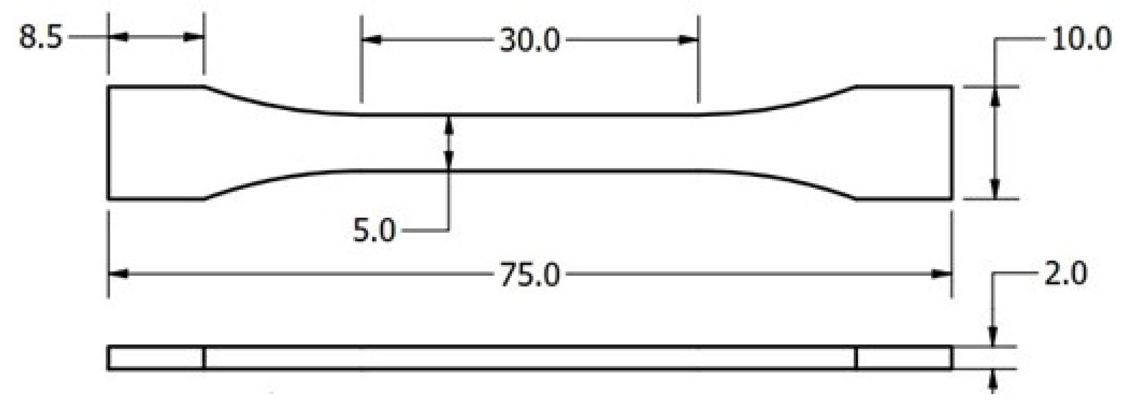
Figure 2.
Plan and front elevation views of a tensile test film specimen. The film is mm thick and 5 mm wide, with plastic gripping plates (2 mm thick) bonded on both top and bottom faces at each end.
Figure 2.
Plan and front elevation views of a tensile test film specimen. The film is mm thick and 5 mm wide, with plastic gripping plates (2 mm thick) bonded on both top and bottom faces at each end.
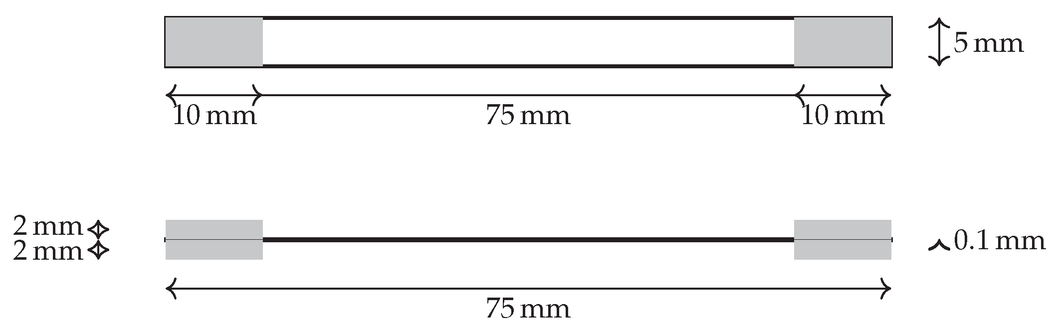
Figure 3.
Schematic diagram showing the four lamination configurations: unlaminated (0S), one-side half lamination (1S-H), one-side full lamination (1S-F), and two-side full lamination (2S-F). Hatched areas indicate the applied laminating film on the substrate surfaces.
Figure 3.
Schematic diagram showing the four lamination configurations: unlaminated (0S), one-side half lamination (1S-H), one-side full lamination (1S-F), and two-side full lamination (2S-F). Hatched areas indicate the applied laminating film on the substrate surfaces.
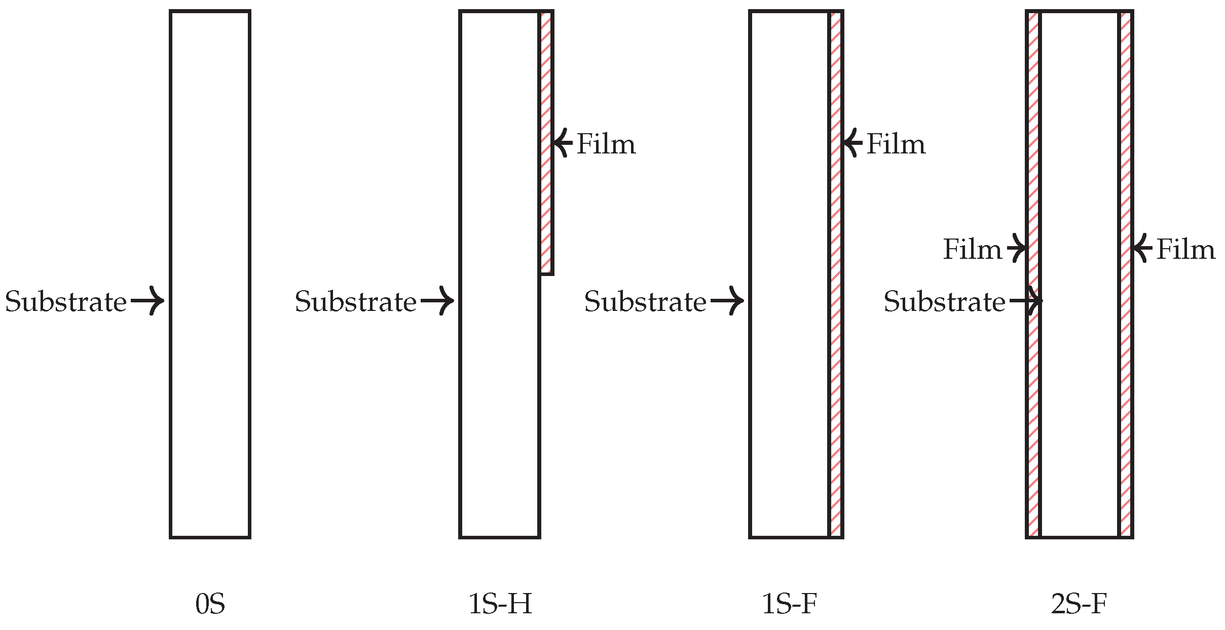
Figure 4.
Representative images of the 0.1-mm PET film tensile test specimens.
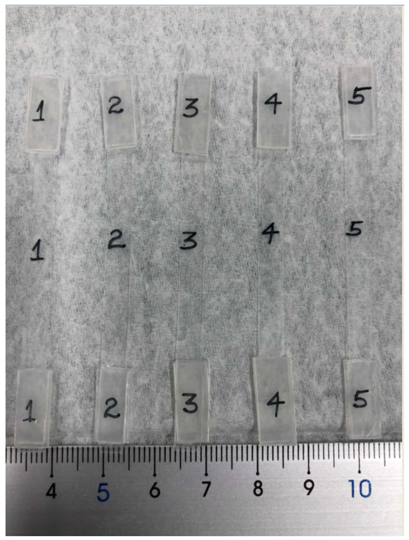
Figure 5.
Representative images of unlaminated and film-laminated tensile specimens. The 1S-F configuration shown in (b) and (d) is representative of other laminated specimen configurations. Lamination was performed using 0.1 mm thick PP or PET films bonded to the specimen surfaces with a plastic-compatible adhesive.
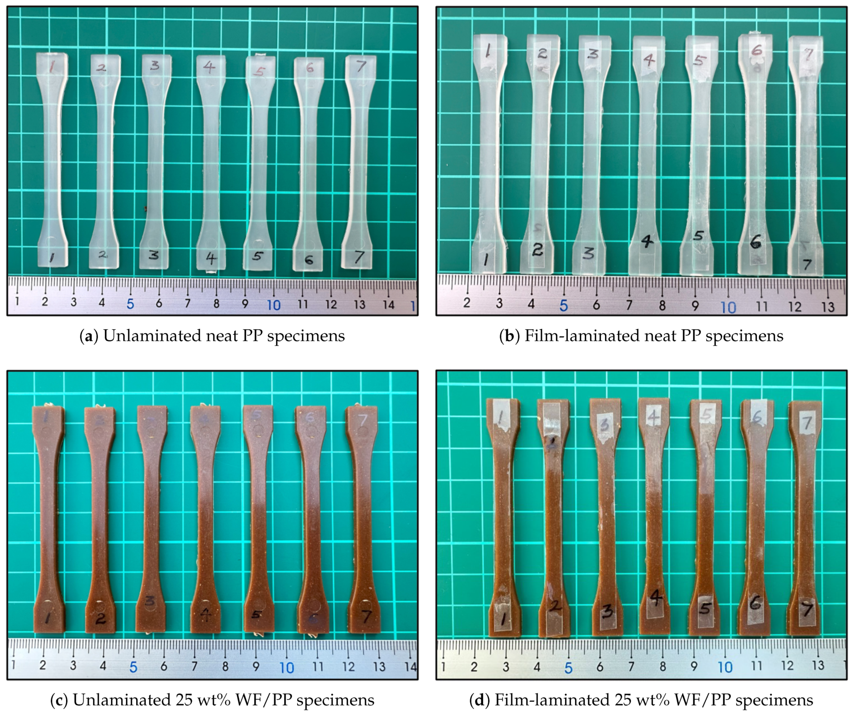
Figure 6.
Surface roughness profiles of unlaminated neat PP and 25 wt% WF/PP specimens, plotted for both transverse and longitudinal directions.
Figure 6.
Surface roughness profiles of unlaminated neat PP and 25 wt% WF/PP specimens, plotted for both transverse and longitudinal directions.
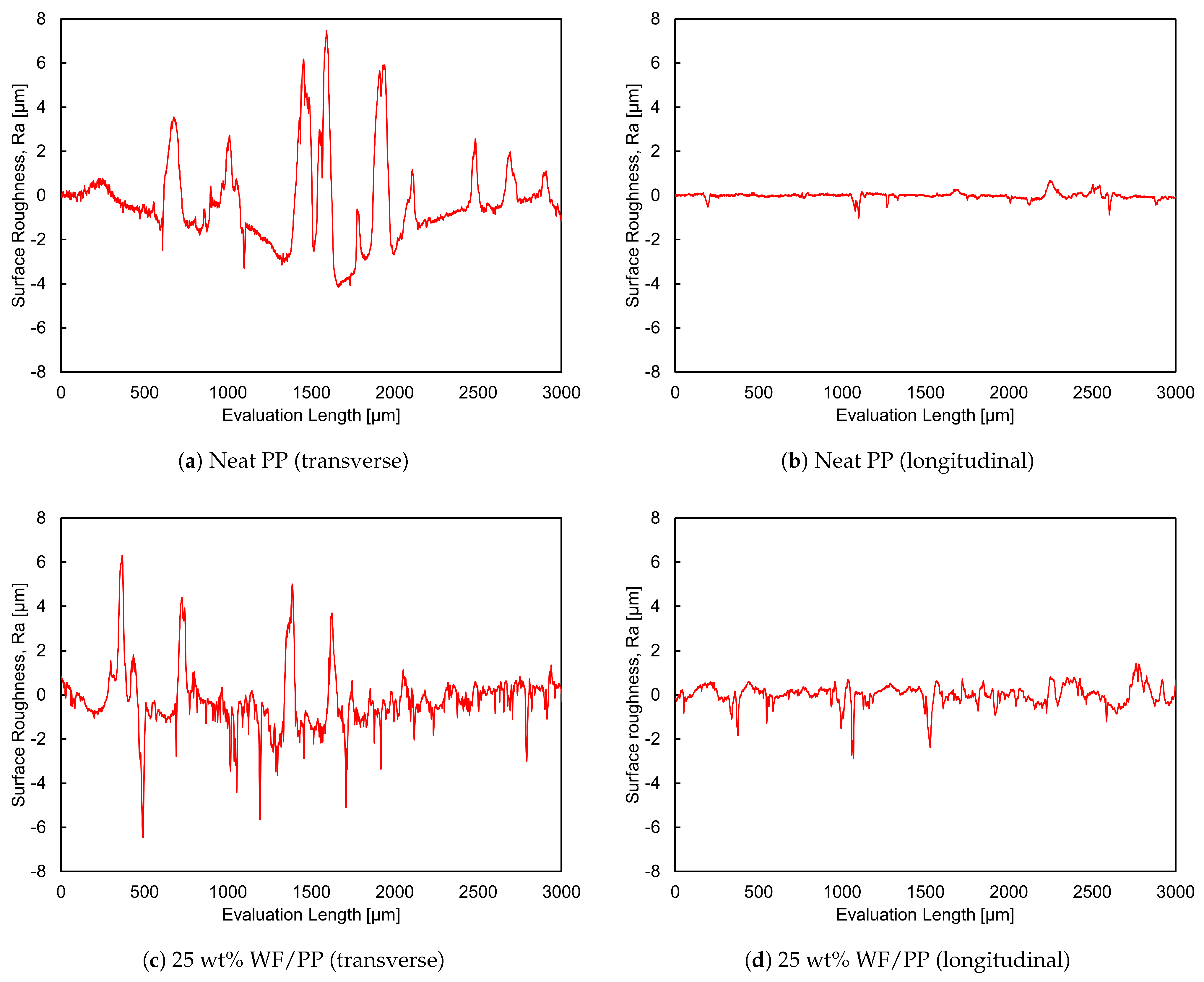
Figure 7.
Representative surface roughness profiles of 0.1 mm PP and PET laminating films. Measurements were conducted without a specific orientation relative to the film’s production direction.
Figure 7.
Representative surface roughness profiles of 0.1 mm PP and PET laminating films. Measurements were conducted without a specific orientation relative to the film’s production direction.
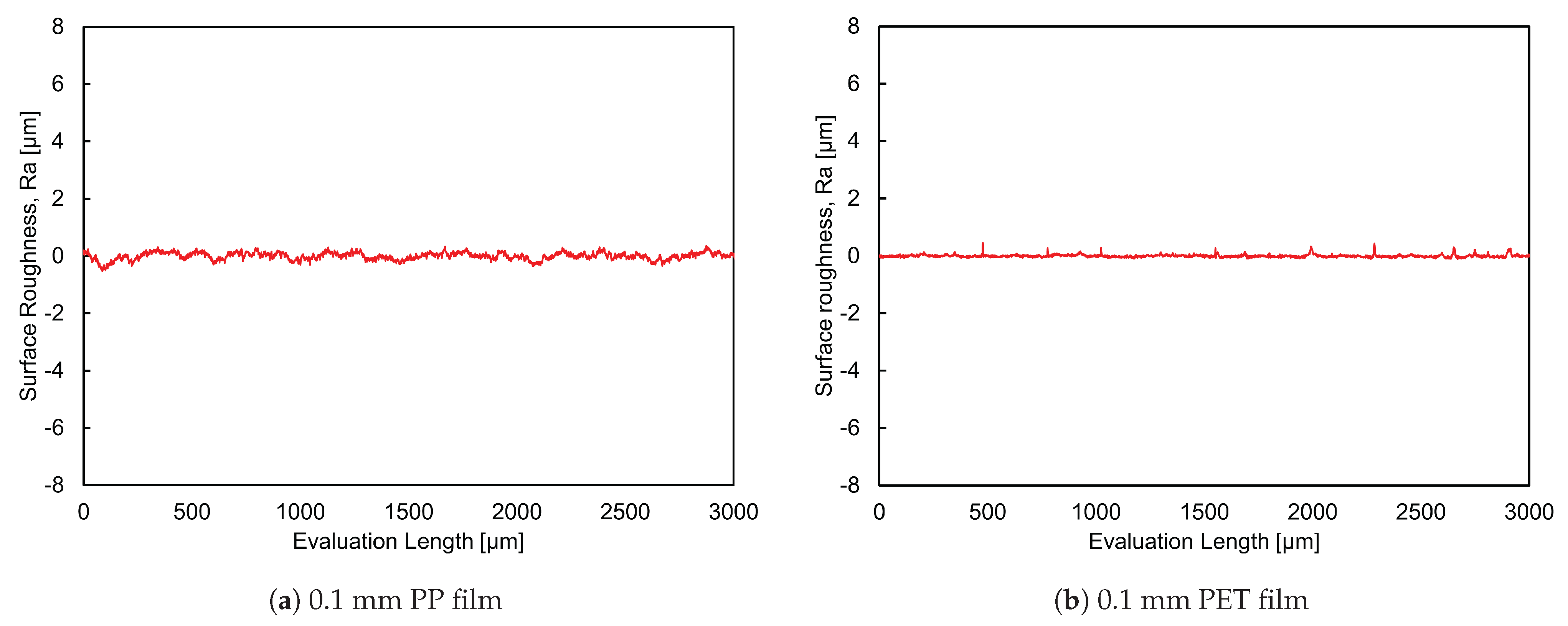
Figure 8.
Scanning electron micrographs showing the surface morphology of 25 wt% WF/PP composites. Panels (a) and (b) show the unlaminated surface at two different magnifications. Panels (c) and (d) show the surface of composites laminated with a 0.1 mm PET film, also at two different magnifications. Scale bars are provided in each image for reference.
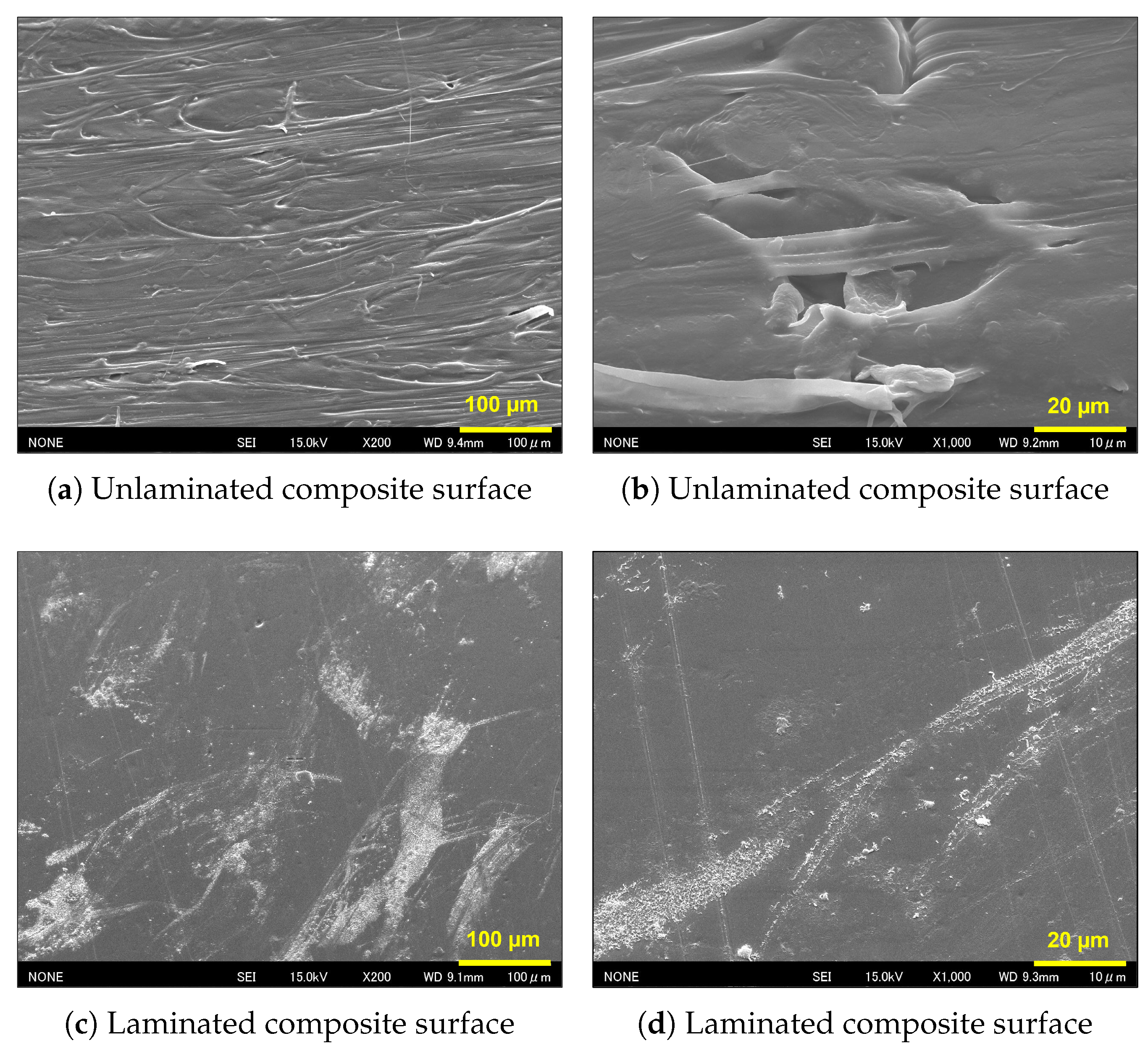
Figure 9.
Tensile stress–strain curves of 0.1 mm PP and PET films.
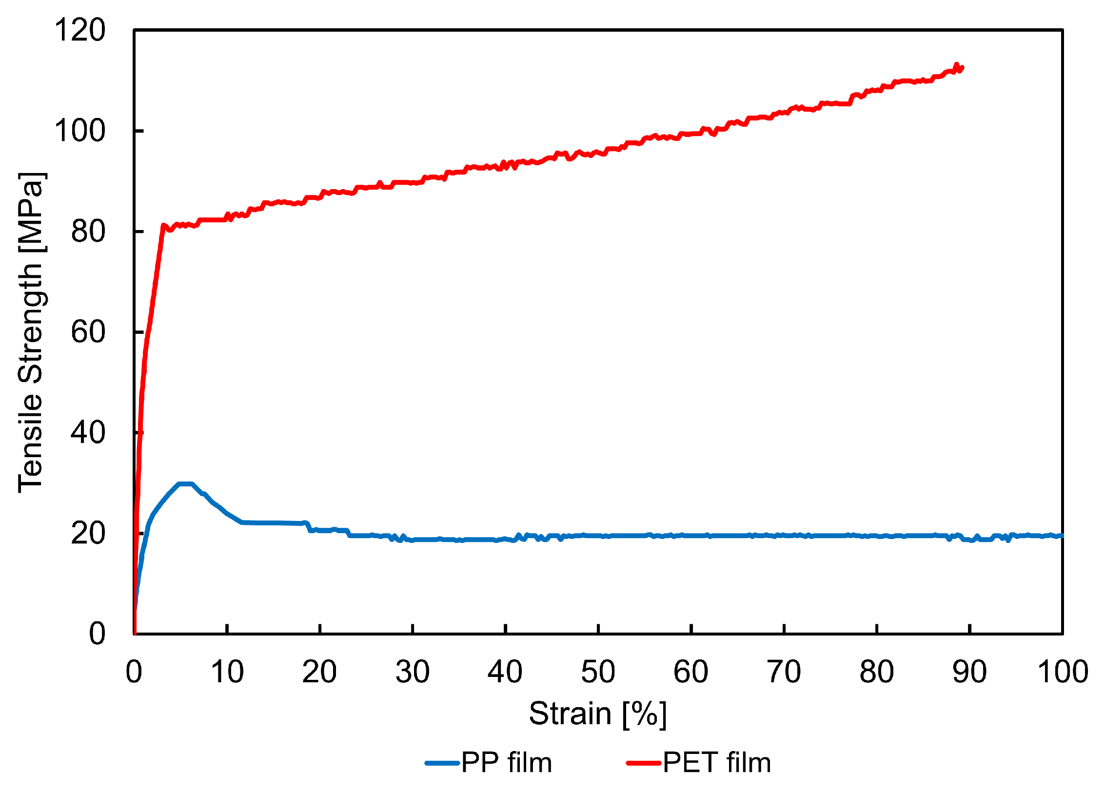
Figure 10.
Representative stress–strain curves of neat PP and 25 wt% WF/PP composites laminated with 0.1 mm PP or PET films across different lamination configurations (0S, 1S-H, 1S-F, 2S-F). (a) Neat PP laminated with PP films. (b) Neat PP laminated with PET films. (c) 25 wt% WF/PP laminated with PP films. (d) 25 wt% WF/PP laminated with PET films.
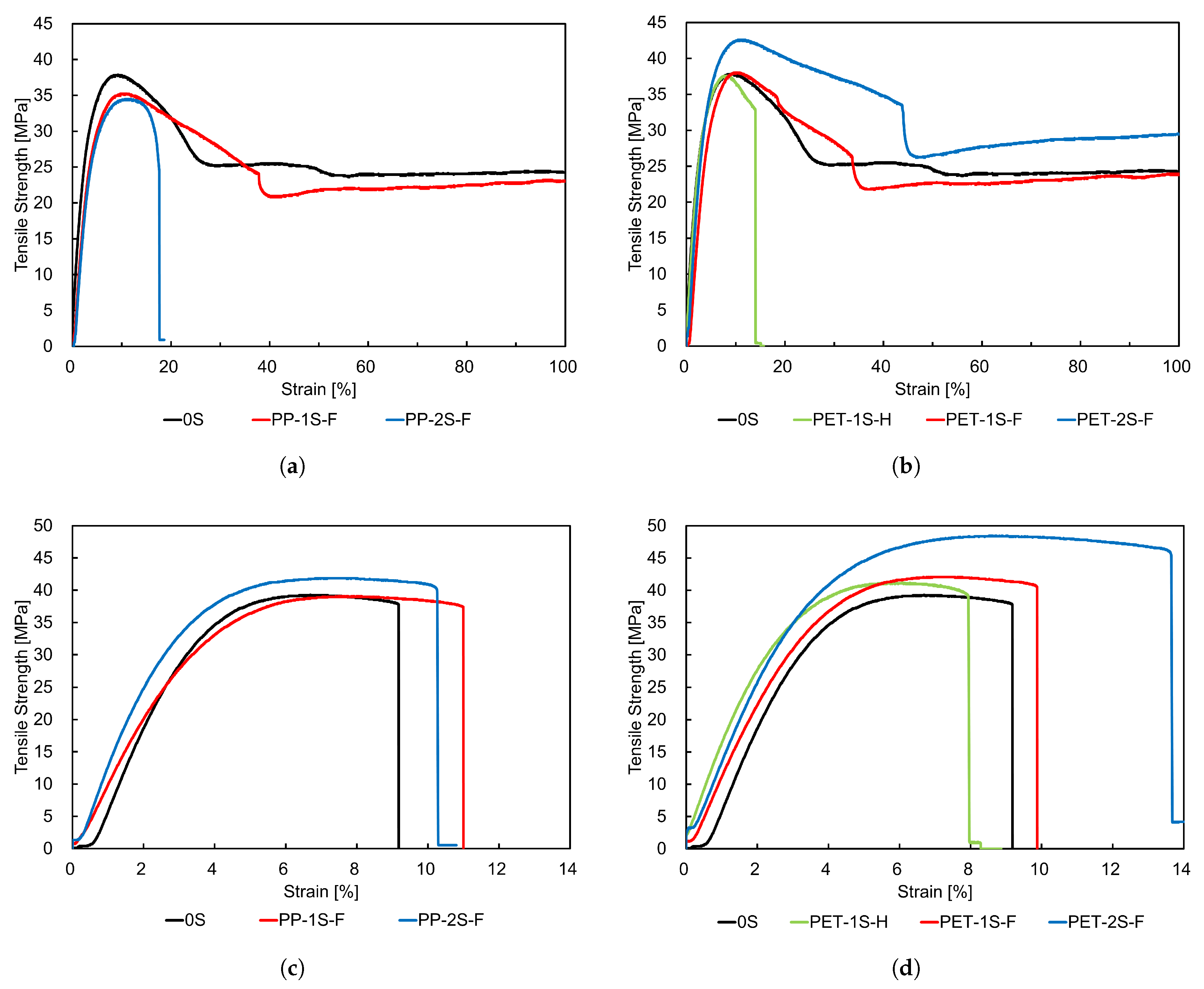
Figure 11.
Scanning electron micrographs of the fracture surfaces of 25 wt% WF/PP composites after tensile testing. Panels (a), (b), and (c) correspond to unlaminated, PP-laminated, and PET-laminated specimens, respectively. The fractured cross-section reveals two distinct areas: a rough, bumpy region and a smoother, whitened region.
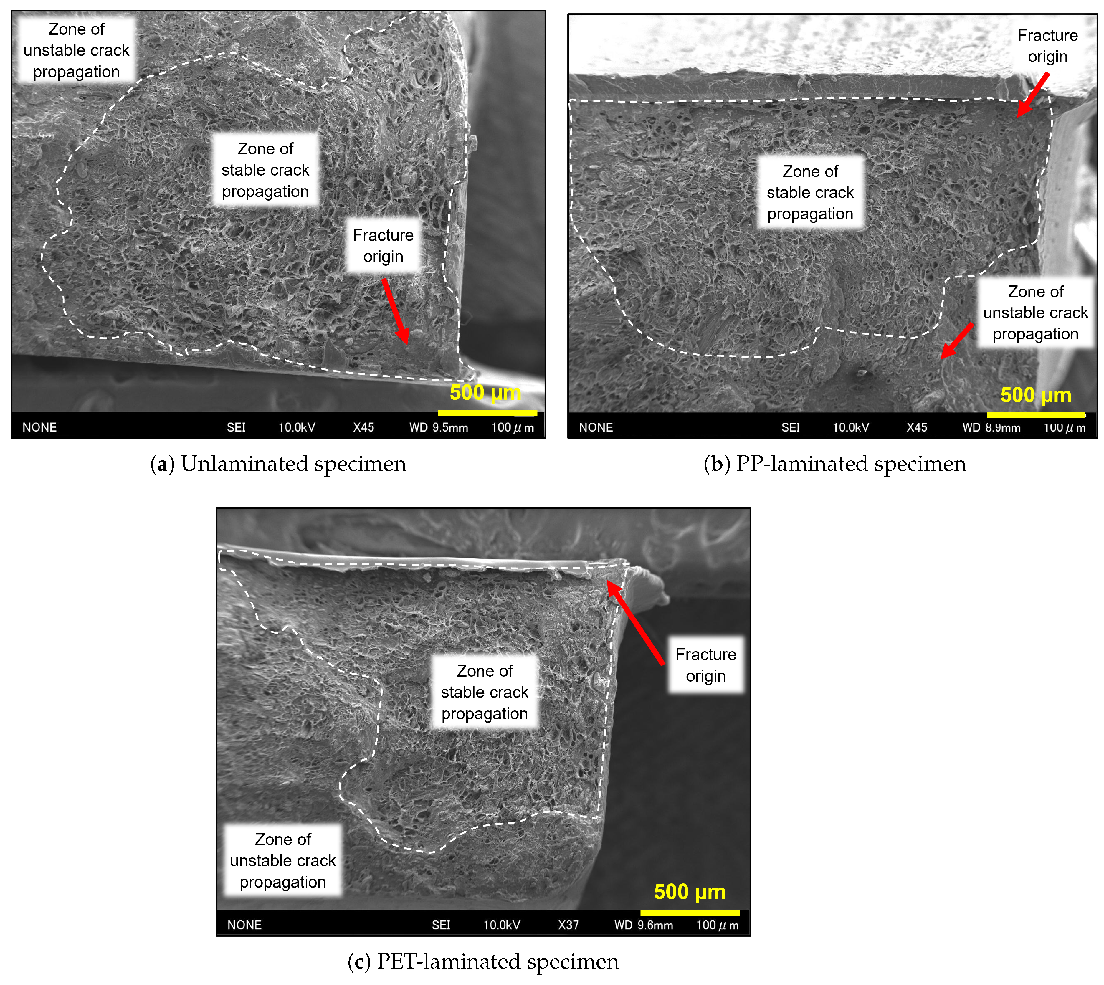

Table 1.
Surface roughness of unlaminated specimens measured in transverse and longitudinal directions
Table 1.
Surface roughness of unlaminated specimens measured in transverse and longitudinal directions
| Material | Transverse [µm] | Longitudinal [µm] |
|---|---|---|
| Neat PP-0S | 1.56 (12.00) | 0.12 (10.58) |
| 25 wt% WF/PP-0S | 0.86 (6.14) | 0.31 (2.53) |
Note: Values in parentheses indicate the coefficient of variation (CV%) based on replicate measurements.
Table 2.
Surface roughness of laminating films
| Film | [µm] |
|---|---|
| PP film | 0.10 (2.44) |
| PET film | 0.03 (1.40) |
Note: Values in parentheses indicate the coefficient of variation (CV%) based on replicate measurements.
Table 3.
Tensile properties of PP and PET films
| Film Type | Tensile Strength (MPa) |
Fracture Strain (%) |
|---|---|---|
| PP film | 29.5 (2.31) | NF (>100) |
| PET film | 113.2 (2.80) | 88.1 (1.47) |
Note: Values in parentheses are coefficients of variation (CV%) based on replicate tests. "NF" indicates no fracture observed up to 200% strain.
Table 4.
Tensile properties of unlaminated and laminated neat PP and 25 wt% wood fiber-reinforced PP composites.
Table 4.
Tensile properties of unlaminated and laminated neat PP and 25 wt% wood fiber-reinforced PP composites.
| Specimen | Laminating Film | Lamination Type | Tensile Strength [MPa (CV%)] |
Lamination Strength Ratio |
Fracture Strain [%] |
|---|---|---|---|---|---|
| Neat PP | — | 0Sb | 37.3 (1.42) | 1.00 | NFc |
| PP | 1S-F | 35.8 (2.15) | 0.96 | NF | |
| PP | 2S-F | 34.9 (1.70) | 0.94 | 18.61 (4.70) | |
| PET | 1S-H | 38.0 (0.30) | 1.02 | 14.35 (6.05) | |
| PET | 1S-F | 38.4 (1.40) | 1.03 | NF | |
| PET | 2S-F | 41.9 (1.60) | 1.12 | NF | |
| 25 wt% WF/PP | — | 0Sb | 39.3 (0.71) | 1.00 | 9.75 (1.85) |
| PP | 1S-F | 39.3 (0.46) | 1.00 | 10.60 (3.27) | |
| PP | 2S-F | 41.3 (1.86) | 1.05 | 10.35 (6.13) | |
| PET | 1S-H | 40.7 (2.27) | 1.04 | 7.74 (7.83) | |
| PET | 1S-F | 41.6 (1.40) | 1.06 | 10.14 (4.52) | |
| PET | 2S-F | 47.6 (1.18) | 1.21 | 13.19 (8.99) |
a Lamination Strength Ratio (LSR) is defined as , where is the tensile strength of the laminated specimen, and is that of the unlaminated reference specimen. b 0S indicates the unlaminated control specimen used as a reference. c NF: No fracture observed up to 200% strain.Values in parentheses indicate the coefficient of variation (CV%) based on five replicate tests.
Table 5.
Volume fractions of substrate and laminating films for neat polypropylene (PP) and 25 wt% wood fiber-reinforced PP composites.
Table 5.
Volume fractions of substrate and laminating films for neat polypropylene (PP) and 25 wt% wood fiber-reinforced PP composites.
| Specimen Type | Laminating Film |
Lamination Type |
Substrate Volume Fraction () |
Film Volume Fraction () |
|---|---|---|---|---|
| Neat PP | — | 0S | 1.00 | 0.00 |
| PET | 1S-H | 0.98 | 0.02 | |
| PP/PET | 1S-F | 0.95 | 0.05 | |
| PP/PET | 2S-F | 0.91 | 0.09 | |
| 25 wt% WF/PP | — | 0S | 1.00 | 0.00 |
| PET | 1S-H | 0.98 | 0.02 | |
| PP/PET | 1S-F | 0.95 | 0.05 | |
| PP/PET | 2S-F | 0.91 | 0.09 |
[t] Notes: Volume fractions and represent the relative volume of the substrate and laminating film, respectively, within each composite specimen. Lamination types are abbreviated as: 0S = unlaminated; 1S-H = half coverage on one surface; 1S-F = full coverage on one surface; 2S-F = full coverage on both surfaces. "—" indicates no laminating film applied.
Table 6.
Comparison between theoretically predicted and experimentally measured tensile strengths for various lamination configurations.
Table 6.
Comparison between theoretically predicted and experimentally measured tensile strengths for various lamination configurations.
| Specimen | Laminating Film | Lamination Type | Theoretical Strength () [MPa] |
Experimental Strength () [MPa] |
Model Strength Ratioa () |
|---|---|---|---|---|---|
| Neat PP | PP | 1S-H | 37.0 | — | — |
| PP | 1S-F | 36.8 | 35.8 | 0.97 | |
| PP | 2S-F | 36.4 | 34.9 | 0.96 | |
| PET | 1S-H | 38.3 | 38.0 | 0.99 | |
| PET | 1S-F | 39.3 | 38.4 | 0.98 | |
| PET | 2S-F | 41.1 | 41.9 | 1.02 | |
| 25 wt% WF/PP | PP | 1S-H | 39.0 | — | — |
| PP | 1S-F | 38.7 | 39.3 | 1.02 | |
| PP | 2S-F | 38.1 | 41.3 | 1.08 | |
| PET | 1S-H | 40.4 | 40.7 | 1.01 | |
| PET | 1S-F | 41.3 | 41.6 | 1.01 | |
| PET | 2S-F | 43.1 | 47.6 | 1.10 |
a Model Strength Ratio (MSR) is defined as , where is the experimentally measured tensile strength and is the theoretical value estimated using the rule of mixtures. Values above 1.00 indicate that the experimental strength exceeds the theoretical prediction.
Disclaimer/Publisher’s Note: The statements, opinions and data contained in all publications are solely those of the individual author(s) and contributor(s) and not of MDPI and/or the editor(s). MDPI and/or the editor(s) disclaim responsibility for any injury to people or property resulting from any ideas, methods, instructions or products referred to in the content. |
© 2025 by the authors. Licensee MDPI, Basel, Switzerland. This article is an open access article distributed under the terms and conditions of the Creative Commons Attribution (CC BY) license (http://creativecommons.org/licenses/by/4.0/).
Copyright: This open access article is published under a Creative Commons CC BY 4.0 license, which permit the free download, distribution, and reuse, provided that the author and preprint are cited in any reuse.


