
Submitted:
30 June 2025
Posted:
30 June 2025
You are already at the latest version
Abstract
Advancement of compact atomic clocks has centered on reducing footprint and power consumption. Such developments come at the cost of the clock’s stability performance. Various commercial and military applications demand reduced size, weight, and power (SWaP) requirements but desire an enhanced stability performance to what is achieved with the lower-profile standards, such as Microchip’s Chip-Scale Atomic Clock (CSAC) or Miniature Atomic Clock (MAC). Furthermore, a high-performing space-rated clock will enhance small satellite missions by providing capability for alternate PNT, one-way radiometric ranging, and eventual lunar PNT purposes. The MAC is a strong candidate as it has modest SWaP parameters. Enhanced performance improvement to the MAC, particularly in the medium to long-term stability over a day and beyond will strengthen its candidacy as an on-board reference clock in small satellite missions and other ground-based applications. In this work, using thermal methods we demonstrate an improvement of the MAC performance by at least a factor of five, showing a superior stability of σy = 4.2e-13 compared to the best-performing miniaturized standard on the market for averaging intervals of τ>1e4 s up to 4 days.
Keywords:
miniature atomic clock (MAC)
; chip-scale atomic clock (CSAC)
; alternate-PNT
; space navigation
1. Introduction
Atomic clock technology has revolutionized ground and space applications that require precision positioning, navigation, and timing (PNT) [1,2,3]. The development of coherent population trapping coupled with advancements in MEMS devices enables the production of compact atomic clocks [4,5]. The advent of Miniature Atomic Clocks (MACs) and Chip-Scale Atomic Clocks (CSACs) that operate with lower size, weight. And power (SWaP) requirements while maintaining superior long-term performances over their crystal oscillator counterparts has strengthened the PNT field [6]. MACs and CSACs are now ideal candidates for situations in which the stability of an atomic frequency standard was previously inaccessible. Current application of the compact atomic clocks includes ground-based operation as holdover devices for telecommunications base stations [7] and implementation in GNSS receivers for improved positioning performance and security against spoofing and jamming attacks [8,9,10]. Now, the military, space agencies, and commercial developers look to the implementation of the devices on small satellites.
The extensive commercialization of low-Earth orbit (LEO) in recent years and NASA’s plans to establish a sustained lunar presence with the Artemis program has resulted in an accelerating number of small satellite missions. Reduced reliance on ground control for these missions has created a demand for autonomous navigation and positioning capabilities for small spacecraft [11]. In 2019, the International Space Exploration Coordination Group, consisting of 27 national space agencies, marked precise onboard timekeeping for autonomous navigation as a critical technology in their Global Exploration Roadmap [12]. A major limitation to the navigational precision for spacecraft the rely on measurements from an onboard clock is the induced positioning error from the clock instability. The listed requirement for absolute position knowledge is < 0.4 m (GER-027) with an emphasis on longer intervals between synchronization with ground stations. Hence, a space-qualified clock with an excellent long-term stability is necessary to achieve small satellite mission autonomy.
One-way radiometric ranging is a promising method for autonomous spacecraft navigation. Tight synchronization with a ground reference for precise computation of signal transmission time is required in this method. The noise in typical crystal oscillators aboard spacecraft precludes their use as a stable frequency reference [13]. To accommodate the size and power constraints on small spacecraft, compact atomic clocks have been proposed as a stable frequency reference. Multiple studies have characterized the performance of the CSAC as a candidate for one-way radiometric tracking through simulations and technology demonstration missions. Simulations of CSAC-driven one-way radiometric ranging for orbit determination of CubeSats in LEO and lunar orbit demonstrate positioning estimation errors in the solution on the order of hundreds of meters – the errors greatly exacerbated by the degraded clock performance from the temperature variation seen in an orbital period [14,15]. Ground testing and modeling of the CSAC paired with a software defined radio also demonstrated that the resulting range precision could allow for orbit determination, but the long-term stability of the clock directly affected the positioning estimation error [13]. A NASA demonstration of this payload in lunar orbit showed that the orbit determination solution obtained from the one-way range data with the CSAC resulted in positioning estimation errors up to 10 km, an order of magnitude degraded from traditional two-way tracking techniques [16]. The positioning performance demonstrated in these studies is suitable for missions with moderate navigation constraints. Given that the onboard clock was a major contributor to positioning error, a standard with a superior long-term stability, such as the MAC, will expand the capabilities of one-way radiometric ranging to low-SWaP missions with more rigorous navigation demands. These studies also exhibit the impact of the clock’s thermal environment on its stability performance and subsequent stability performance. Further reduction in temperature sensitivity to onboard clocks will enhance their long-term stability as well as alleviate the burden of precise modeling of temperature effects for optimal positioning estimation.
As it stands, Microchip has not released a radiation-tolerant MAC. Outlined above, the production of a space-rated MAC would improve the accuracy of a host of small spacecraft navigation and positioning applications for which the lower-grade CSAC is one of few candidates.
Furthermore, the long-term stability performance (averaging intervals τ > 103 s) of the compact clocks is of notable importance to applications outside of GNSS coverage or requiring enhanced spacecraft autonomy. The impact of thermal cycling over a satellite’s orbital period on clock stability is evident at these longer timescales. The overall temperature variation experienced by the electronics aboard small satellites in Earth or lunar orbit will depend on spacecraft design and orbit type, but the relatively small mass of the spacecraft makes it particularly susceptible to changes in thermal flux [17]. Thermal analyses of small satellites found that temperature swings on the order of tens of degrees are experienced throughout their orbit [18]. Development in the MAC’s thermal sensitivity will therefore improve its long-term stability and strengthen its candidacy as a space clock for one-way ranging missions, lunar PNT applications, and other satellite missions operating with limited GNSS availability.
This work quantifies the stability improvement of the MAC with enhanced thermal confinement. The studies performed in this paper utilize external thermal control, but further improvement to the clock’s thermal isolation through passive methods is another possibility. While these thermal enhancements might come at the expense of the device’s size, weight, and power, the reviews in Section 1 and Section 2 demonstrate the applications that benefit from this superior performance.
Section 2 of this paper evaluates and compares the predicted positioning error of the MAC and other low-SWaP standards and its implication for small-satellite PNT purposes. Section 3 provides an overview of the measurement methods and the implementation of the thermal control systems for this work. Section 4 analyzes the stability performance of the MAC with the applied thermal control. Section 5 then evaluates the positioning performance with the stability improvement from thermal control and discusses the relevance to timing and positioning applications. Finally, Section 6 outlines future work.
2. Position Error of the Low-SWaP Clocks
The estimated positioning error from a clock at any time t can be calculated as the product
where c is the speed of light and x(t) is the predicted time error of the clock. The predicted time error accumulated after an initial synchronization is given as
where x0 is the initial time offset, y0 is the sum of the initial frequency offset and the average environmentally-induced offset, D is the frequency drift, and ε(t) is the time error induced by the random frequency fluctuations on the quadratic [19]. This latter term is dependent on the dominant noise type of the oscillator for a given averaging interval, τ, and is characterized with the Allan Deviation (ADEV), σy(τ). Thus, the positioning error is a function of the averaging interval. For averaging periods sufficiently shorter than the length of the data set and the removal of frequency offset and drift from the data, the random predicted time error for a given averaging interval is
where k is the coefficient dependent on the governing noise type for the averaging period. The dominant noise type is easily observed from the slope of the clock’s Allan Deviation [20]. The value of this coefficient for the given noise type and corresponding ADEV slope is displayed in Table 1.
Since the coefficient is unity for white frequency noise and the time error from the drift term in Equation (1) is negligible at small timescales, the time error over a given averaging interval is commonly taken as τ σy(τ) when estimating clock performance. However, the focus of this work is on clock behavior over longer timescales (τ > 103 s), where flicker frequency eventually becomes dominant. Thus, the resulting positioning error over a specified averaging interval for an oscillator with zero phase and frequency offset can be calculated as
where the values of the coefficient k are taken from Table 1. From Equation (4), the dependence of positioning performance on clock stability and averaging interval is clearly seen.
Now, an evaluation and comparison of the positioning performance of low-SWaP atomic clocks is performed here utilizing Equation (4). A space-rated CSAC was developed by Microchip to act as a stable on-board reference for small satellites in LEO for alternative PNT, geolocation, and communication purposes [21]. Safran released a low-profile rubidium standard, the mRO-50, for aerospace application [22]. However, Microchip has not yet released a space-rated version of its MAC. While the CSAC is the lightest and lowest-power commercially available atomic clock [23], its performance is an order of magnitude worse than that of the MAC. The operating parameters and calculated positioning errors of Microchip’s MAC and CSAC, and Safran’s mRO-50 are compared in Table 2.
The positioning error induced by the instability of the MAC is an order of magnitude less than that of the CSAC and is consistently lower than the mRO-50 across all averaging intervals. No space-rated standard with the stability and profile of the MAC is currently commercially available. There exist many functions which would benefit from a stable clock with a small footprint but aren’t so conservative as to require the tight operating conditions of the CSAC. The MAC is a strong candidate in these cases. However, to achieve the autonomous navigation capability outlines in the Global Exploration Roadmap, further development in the long-term stability of the low-SWaP clocks is necessary to reduce dependence on ground-based or GNSS-based timing corrections [12]. The next portion of this section examens the performance of low-SWaP clocks in notable earth orbit and deep space PNT applications and evaluates the need for further long-term improvements.
Distributed small satellite systems are an active area of research for complementary PNT purposes. Recently, the U.S. Space Force created the Resilient GPS (R-GPS) program to augment the current 31-satellite GPS constellation with several smaller satellites [24]. Four commercial developers were awarded agreements to design lighter spacecraft capable of carrying disaggregated GPS payloads to operate in the constellation’s medium Earth orbit (MEO). A stable low-SWaP clock will be necessary to meet the operational requirements of these satellites. Given the orbiting period and consequently the resynchronization period of satellites in MEO (τ ≈ 12 hrs), the long-term stability of the onboard clock will be vital in maintaining system performance.
Independent of GPS, the development of small satellite constellations in LEO the utilize optical crosslinks (and time transfer) for alternative PNT is of interest for military and commercial application [25]. Spacecraft-to-spacecraft time transfer via a laser link will be demonstrated with the upcoming CubeSat Laser Infrared Crosslink (CLICK) mission [26]. Major constraints to the laser time transfer technique are the laser power consumption and the required precision of the pointing system for each set of lasing measurements. Stable onboard clocks would allow individual satellites to maintain their performance for longer periods, increasing the interval necessary between time corrections. This would conserve laser power and reduce the number of measurements made each orbital period by the instrument. Ground-to-spacecraft optical time transfer has been demonstrated by the CubeSat Handling of Multisystem Precision Timing Transfer (CHOMPTT) mission [27]. This was the first CubeSat satellite mission to operate with a CSAC in LEO. The stability of the CSAC limited the timing performance of the satellite at longer timescales, where one orbital period (τ = 6x10³ s) corresponded to a timing error on the order of tens of nanoseconds. Employment of the MAC would reduce this error by a factor of 3-4 due to its superior stability performance at these longer timescales [28]. The utilization of laser links such as those in the CLICK and CHOMPTT missions demonstrates the communication and PNT capabilities that future distributed small satellites systems will have in LEO [29]. The development of a space-qualified clock with an excellent long-term stability will strengthen these systems through reduced reliance on GNSS or intersatellite timing corrections.
Outside of Earth orbit, low-SWaP clock are potential candidates in cis-lunar and deep space navigation applications. As a method of providing space communication and navigation services on the moon, NASA’s Goddard Space Flight Center has proposed a network of lunar-orbiting satellites capable of providing PNT services to lunar users [30]. Utilization of small satellites (< 180 kg) and consequently low size, weight, and power onboard electronics for a lunar constellation to meet cost constraints is of interest. Compact atomic clocks, such as the CSAC and MAC, are leading onboard clock suggestions due to their minimal operating parameters [31,32]. A requirement on the performance of this PNT service is an absolute position knowledge of ±10m for surface operations (LCRNS.3.0570) [33]. The stability of the onboard clock will directly affect the positioning precision provided by the constellation. While the magnitude of the ranging error will also be dependent on other factors, such as the orbit type, a case study on the design of such a constellation with timing corrections supplemented by the Earth-based GPS demonstrated that Microchip’s MAC resulted in approximately half the lunar User Equivalent Ranging Error (UERE) as the CSAC for all simulated orbit types [34]. Furthermore, the timing errors in these computations primarily depend on the length of the period in which the satellite has no visibility with GPS, which was up to a period of τ = 3.9x10³ s for the studied orbits. This makes the long-term stability of the onboard clock at these timescales critical to achieving the required positioning performance.
Compact atomic clocks have been explored for a variety of other lunar positioning and navigation applications. The CSAC and MAC are candidates for the onboard clock for the autonomous Endurance rover, set to launch in the 2030s [35]. One suggested method to attain the position for this rover is via Doppler shift observables from a single satellite [36]. A clock sensitivity study found that the convergence time to achieve the required sub-10 m lunar surface positioning accuracy was over 50 hours for the CSAC and less than 12 hours for the MAC. The CSAC was thus not a recommended candidate for this method due to its instability. Another proposed PNT scheme is the use of pseudolites to provide regional coverage at the lunar south pole [37]. This method also notes the potential of intermittent GNSS timing corrections, which necessitates the use of precise onboard references to minimize error during outage periods.
The above positioning and performance requirements demonstrate the importance of the long-term stability of the onboard clock in LEO, MEO, and lunar small satellite missions. The current limitations of the low-SWaP clocks must be addressed to meet these performance goals and enhance mission autonomy. Enhanced thermal management of the low-SWaP clocks, particularly in the higher-grade standards such as the MAC, is a method to address the limitations in their long-term performance.
3. Methodology
Perturbation due to thermal variation is a major limiting factor for a clock’s long-term stability. The stability of an atomic clock is tied to the measurement of a microwave resonance frequency between two hyperfine ground states of an alkali atom (rubidium for the MAC and cesium for the CSAC). Temperature changes in the clock’s physics package affect buffer gas collisions, inducing frequency shifts [5]. Furthermore, the AC Stark Shift results from changes in the laser temperature, which causes laser intensity variations affecting the clock stability and drift. Both processes degrade the clock performance. Thus, the employment of more stringent thermal confinement to the device will result in an improved frequency stability. Figure 1 shows the setup of the MAC performance testing in a thermal control box that was designed and built. Three different thermal conditions were tested: without external control, with the Watlow control system, and with the Thorlabs thermal control system.
Microchip’s legacy MAC SA.25m was used for our studies. To determine the improvement in the thermal stability of the MAC, two types of thermal control methods were implemented in addition to the initial characterization of the device.
The preliminary characterization of the MAC was conducted in its ambient environment. This was necessary as the manufacturer’s data is only available for three averaging times (all τ < 102 s) and individual instrument performance shows some variation from the specified values. The first thermal confinement test was designed to achieve an intermediate level of thermal control. A system with a Watlow F4DH Controller [38] was constructed and deployed to gauge clock performance. The datasheet temperature stability of this device for the testing conditions is ±0.75°C. In testing, the controller achieved a better performance with a measured temperature stability of ±0.10°C (calculated as 3-sigma). These tests characterized MAC performance with moderate improvements to thermal sensitivity. For an improved thermal stability, a control system utilizing a Thorlabs TC300B Temperature Controller [39] was implemented. The datasheet temperature stability of the Thorlabs controller is ±0.1°C, and its measured temperature stability was ±0.075°C. These tests characterized MAC performance with further improvements to its thermal sensitivity. The remainder of this section is dedicated to the setup for each system.
3.1. Ambient Characterization of the MAC
Prior to application of external thermal control, several stability performance tests were conducted to characterize the individual behavior of the clock. While the performance values for the device are provided in the manufacturer’s datasheet, individual characterization is necessary to obtain instrument specific values, particularly to evaluate the long-term performance, which is of interest to this study. The preliminary performance runs were conducted with the MAC situated on its evaluation board and exposed to the ambient environment at 23 ± 2°C. This setup is shown as configuration [A] in Figure 1. Several tests were conducted and compared with the Allan Deviation values from the manufacturer’s datasheet. The MAC performed better than the stated datasheet parameters, but its performance was consistent across each run. Thus, the results reflect only one of these preliminary characterization runs.
The overlapping Allan Deviation was used to evaluate clock performance [20]. This metric is the standard measure of clock stability and characterizes the performance of the device from its noise effects independent of systematic errors, such as a constant temperature offset. A Symmetricom 3120A Phase Noise Test Probe was used to measure phase variations of the MAC SA.35m with reference to an SRS FS725 Rubidium Frequency Standard.
The largest temperature fluctuations experienced by the clock occur due to diurnal cycles. Thus, the largest frequency dispersion in the clock due to this cyclical environmental temperature variation will be most extreme around 12-hour intervals (τ ≈ 4x10⁴ s). A performance run of 7 days in length yields an Allan Deviation with sufficiently low uncertainty for this averaging time. Accordingly, all performance runs contained in this paper are at least 7 days in length.
3.2. Enhanced Thermal Management
An aluminum thermal enclosure was designed and fabricated to fit the MAC and its evaluation board. The enclosure shielded the MAC from any direct air currents and stood on insulative PTFE legs to isolate the clock from the ground platform. The enclosure is shown in Figure 2. A CHOTHERM thermally conductive pad was placed at the interface of the MAC’s evaluation board and the enclosure baseplate to prevent metal-to-metal thermal contact resistance. Two 7W thin-film heaters were mounted on the bottom of the baseplate to be operated through one of the external control systems. This enclosure was used for both tests with the Watlow controller and the Thorlabs controller.
3.2.1. Watlow Thermal Control System
Characterization of the clock with moderate thermal confinement will demonstrate the performance improvement of the clock with modest developments to its thermal environment. The relatively small footprint, low cost, and limited temperature stability of the Watlow F4DH controller made it an ideal device for this demonstration.
The Watlow controller functioned as a PID device. It received a temperature input from a PT100 RTD mounted in the vicinity of the heaters on the enclosure baseplate. This setup is shown as configuration [B] in Figure 1. Based upon the programmed PID bands and the setpoint of the system, the Watlow unit switched an external DC SSR in the circuit with the heaters and their power supply. Since no cooling technique was implemented in the system, a setpoint temperature was chosen above the nominal baseplate operating temperature so that it could be maintained in the case of an increase in ambient temperature. The temperature-induced frequency shift in the device arising from this temperature offset will not be reflected in the performance runs as the Allan Deviation removed any bias in the run.
3.2.2. Thorlabs Thermal Control System
To demonstrate the performance of the MAC with more rigid thermal confinement, the Thorlabs TC300B Temperature Controller was chosen for the tests. This characterization will serve as a baseline for the improvement in stability from precise control or enhanced isolation in the clock’s thermal environment.
Unlike the Watlow controller, the Thorlabs controller provided the capability to directly power and switch the heaters, so no external SSR was necessary. This setup is shown as configuration [C] in Figure 1. We note that a simple thermal controller using an Arduino controller can be designed to bring the temperature control down to 1 mK levels. In the same method outlined in Section 3.1, the stability performance of the MAC was measured over runs at least 7 days in length for all tests.
4. Results
Three stability performance runs are compared corresponding to the thermal confinement scenarios outlined in Section 3: ambient characterization, characterization with moderate thermal confinement with the Watlow controller, and characterization with a tight thermal confinement with the Thorlabs controller. The tests range from 7 to 21 days in length. The longer duration tests reduce the uncertainty on a given averaging interval [20], but the averaging intervals of primary interest (τ > 103 s) have sufficient statistical confidence for comparison across all runs. The temperature fluctuations in the MAC are first discussed for each run before the stability data is presented and performance improvement quantified.
The internal temperature variation from each MAC characterization test is displayed in Figure 3. In the ambient test without applied thermal control, the MAC experienced maximum temperature deviations of from its nominal temperature. As predicted for this case, the temperature variation is cyclical with 24-hour periods. The maxima occur around 3:00 in the afternoon. Two reasons can be attributed to this. The first is that the laboratory in which the tests are conducted is located in the Southwest corner of its building, with windows on an outer wall that experience direct sunlight mid-afternoon. The second is that this time corresponds to when the most lab members are at their stations, elevating the overall room temperature.
Both thermal confinement tests demonstrate over an order of magnitude reduction in the overall temperature variation of the MAC. Figure 3 displays the difference in temperature stability achieved by the two controllers. The test of moderate thermal confinement with the Watlow controller displayed maximum temperature deviations of . The test of more rigorous thermal confinement with the Thorlabs controller demonstrates maximum temperature deviations of .
The stability performance for the three thermal control modes is shown in Figure 3 along with the manufacturer’s listed datasheet values. The MAC performed better than the datasheet values across all levels of thermal confinement. However, the manufacturer’s values are only available out to an averaging interval of τ = 102 s, limiting a comparison at longer intervals.
All runs displayed a similar performance at averaging intervals of τ < 103 s. This region of the Allan Deviation curve reflects white frequency noise (behavior following τ-1/2) and thus would not be expected to exhibit change as a result of reduced temperature variation. Beyond an averaging period of τ = 103 s, the ambient characterization of the MAC exhibits flicker and random walk behavior that reflects the thermal sensitivity and other environmental sensitivities causing drift and drift-rate effects to the device. The stability performance of the MAC in both cases of enhanced thermal confinement shows significant improvement over the ambient characterization beyond τ = 103 s. This indicates that the thermal environment of the MAC has a substantial impact on its performance and is effectively remedied by the applied thermal control.
Moderate thermal confinement of the MAC using the Watlow controller improved its stability by a factor of three over its ambient performance, down to a minimum of σy = 7.0x10⁻¹³ at an averaging period of τ = 4x10³ s. Application of more rigorous thermal confinement improved the stability of the MAC by a factor of five over the ambient case, down to σy = 4.2x10⁻¹³ for an averaging period of τ = 4x10⁴ s up to four days. A summary of the results at longer timescales, between averaging periods of 103 s to 105 s is given in Table 3. As discussed in Section 1, clock performance at these timescales is relevant for autonomous spacecraft operation in LEO, MEO, and deep space. The impact of these results on positioning precision applications is discussed in Section 5.
5. Discussion
As per our knowledge, this is the first demonstration of the long-term performance of the MAC (τ > 103 s) improved with tighter thermal confinement, as shown in Figure 4. The tightest level of thermal confinement (with the Thorlabs controller) demonstrated an improvement in thermal control by a factor of 17 over the ambient case and an improvement in the clock stability by a factor of five. This behavior displays the nonlinear relationship between temperature stability and clock stability. The remainder of this paper exclusively discusses the ambient case and the tightest thermal control case as they demonstrate the performance potential of a MAC equipped with enhanced thermal confinement. The results of these characterizations are compared in Table 4 with the datasheet values of the legacy MAC SA.35m (the clock utilized in this work) and the datasheet values of the MAC SA.57m, the top-performing MAC.
The expected positioning performance with the clocks is also displayed in Table 4. The positioning error induced by the clocks is calculated from Equation (4) in Section 2 with the exception of the frequency drift term so that a comparison of the characterization tests and datasheet values can be performed. As detailed in Section 2, the value of the coefficient k in Equation (4) is based upon the dominant noise type for a given averaging interval, which can be determined from the slope of the Allan Deviation curve. For the characterization tests, the Stable32 processing software computed these slopes, and the values were related to Table 1 to obtain k for optimum prediction. For the datasheet values, white frequency noise was assumed for τ < 103 s and random walk frequency noise was assumed for τ > 104 s. From Table 1, the value of k for both of these noise types is unity.
For timescales τ > 104 s, the MAC outperformed Microchip’s highest-performing MAC by a factor of three, achieving an Allan Deviation down to σy = 3.7x10⁻¹³ at τ = 105 s. The excellent performance at these timescales displays the MAC’s potential for implementation on small satellites in MEO. With orbital periods of roughly 12 hours (τ ≈ 4x10⁴ s), these satellites can be resynchronized with ground stations at this interval.
These results demonstrate that thermal variation in the MAC significantly affects its performance at longer averaging intervals, and a superior stability performance is achieved through tight thermal confinement of the clock. Advancement in the clock’s thermal sensitivity through external control or increased thermal isolation will be particularly important to applications where the clock is subjected to thermal cycling, such as on small spacecraft where the thermal variations on the device will be on the order of tens of degrees while facing the Sun and during occultation behind the Earth [17,18]. The long-term stability (τ > 103 s) realized through enhanced thermal confinement of the MAC will be critical to the positioning and navigation performance of future small satellite missions where autonomous navigation or a decreased reliance on GNSS timing corrections are necessary.
6. Conclusions and Future Work
The results of the thermal confinement studies in this work demonstrate the capability of the MAC as an effective oscillator and its potential as a clock for long holdover ground-based applications and toward space applications that require an improved long-term stability performance. However, it is important to note that the MAC is yet to be space qualified but has the potential to perform better than the CSAC. Our studies were conducted with the legacy MAC SA.35m and achieved a performance surpassing that of the top-performing commercially available MAC, particularly for the averaging times beyond 103 s up to 4 days. We believe the stable behavior seen beyond one day reaching up to four days could very well be extended to a week without many changes in the demonstrated design. Additional thermal confinement studies to gauge further improvement in stability performance of the MAC, utilizing the MAC SA.57m, will inform the development of the thermal isolation of the clock in future models.
Future development of a space-rated MAC with enhanced thermal sensitivity will enable autonomy in small satellite missions with stringent navigation requirements, have the potential to serve as a stable onboard reference in a lunar navigation satellite system and other lunar PNT applications, and augment alternate PNT capabilities of satellites in LEO and MEO.
To realize a reference signal with further enhanced stability, the construction of a clock ensemble consisting of several MACs can be explored. In this, the long-term stability would nearly match that of the best performing clock in the ensemble but increase the reliability of the overall system. Recently, a testbed of a small clock ensemble with an OCXO and three CSACs was studied and achieved a performance that matched the short-term stability of the OCXO and the long-term stability of the best CSAC in the ensemble [40]. An atomic clock ensemble in space (ACES) will be deployed on the International Space Station that takes advantage of the stabilities of a hydrogen maser and a cesium standard to create a clock signal with exceptional short-term and long-term stability for fundamental physics tests [41]. Similarly, employment of a MAC ensemble with improved thermal control on small satellites will strengthen alternate PNT services by providing a superior short-term and long-term stability over that of a single clock. As this work has shown, amelioration of the thermal sensitivity of the MACs will be critical in achieving a high-quality stability performance aiding in future PNT based on small satellites for the Earth, Moon, and beyond.
Supplementary Materials
The following supporting information can be downloaded at the website of this paper posted on Preprints.org, Figure S1: title; Table S1: title; Video S1: title.
Author Contributions
Emily Gokie: experimentation, methodology, investigation, data curation, writing – original draft preparation. Thejesh N. Bandi: conceptualization, methodology, investigation, validation, supervision, project administration, writing – review and editing. All authors have read and agreed to the submitted version of the manuscript.
Funding
MAC and CSAC units were supported by Microchip Inc. No other external funding support was part of this research effort.
Institutional Review Board Statement
Not applicable.
Informed Consent Statement
Not applicable.
Data Availability Statement
We The original contributions presented in this study are included in the article. Further inquiries can be directed to the corresponding author(s).
Acknowledgments
Special thanks to Mr. Jon Omarie for constructing the thermal control testing involving the Thorlabs system, to Mr. James Pugh for the fabrication of the MAC’s enclosure, and to Mr. Bryan Owings of Microchip for the supply of the MAC unit for this work.
Conflicts of Interest
The authors declare no conflicts of interest.
Abbreviations
The following abbreviations are used in this manuscript:
| SWaP | Size, weight, and power |
| CSAC | Chip-scale atomic clock |
| MAC | Miniature atomic clock |
| PNT | Positioning, navigation, and timing |
| GNSS | Global Navigation Satellite System |
| LEO | Low-Earth orbit |
| ADEV | Allan Deviation |
| GPS | Global Positioning System |
| MEO | Medium-Earth orbit |
References
- Bandi, T.N. A Comprehensive Overview of Atomic Clocks and Their Applications. BEMS Reports 2023, 9. [Google Scholar] [CrossRef]
- Mallette, L.A.; Rochat, P.; White, J. An Introduction to Satellite Based Atomic Frequency Standards.; Big Sky, MT, 2008; pp. 1–9.
- Ely, T.A.; Seubert, J.; Bell, J. Advancing Navigation, Timing, and Science with the Deep Space Atomic Clock.; Pasadena, CA, 2014.
- Knappe, S.; Shah, V.; Schwindt, P.D.D.; Hollberg, L.; Kitching, J.; Liew, L.-A.; Moreland, J. A Microfabricated Atomic Clock. Applied Physics Letters 2004, 85, 1460–1462. [Google Scholar] [CrossRef]
- Kitching, J. GPS World. November 2007, pp. 52–57.
- Leading-Edge Technology Enables a Chip Scale Atomic Clock; Microsemi.
- SA.31m, SA.33m, and SA.35m Miniature Atomic Clock (MAC) SA.3xm; Microchip, 2019.
- Calero, D.; Fernandez, E. Characterization of Chip-Scale Atomic Clock for GNSS Navigation Solutions.; Prague, Czech Republic, 2015; pp. 1–8.
- Meng, Y.; Weng, D.; Wu, C.; Zhiyu, H. Chip-Scale Atomic Clock (CSAC) Aided GNSS in Urban Canyons. GPS Solutions 2024, 28. [Google Scholar] [CrossRef]
- Cesium Atomic Clocks to Back up GNSS/GPS Receivers in Communicatoins Networks; Microsemi, 2014.
- Turan, E.; Stefano, S.; Gill, E. Autonomous Navigation for Deep Space Small Satellites: Scientific and Technological Advances. Acta Astronautica 2022, 193, 56–74. [Google Scholar] [CrossRef]
- Global Exploration Roadmap Critical Technology Needs 2019.
- Ely, T.; Towfic, Z.; Sorensen, D. Formulation and Characterization of One-Way Radiometric Tracking with the Iris Radio Using a Chip-Scale Atomic Clock. NAVIGATION: Journal of the Institute of Navigation 2024, 71. [Google Scholar] [CrossRef]
- Rybak, M.M.; Axelrad, P.; Seubert, J.; Ely, T. Chip Scale Atomic Clock-Driven One-Way Radiometric Tracking for Low-Earth-Orbit CubeSat Navigation. Journal of Spacecraft and Rockets 2021, 58, 200–209. [Google Scholar] [CrossRef]
- Rybak, M.; Axelrad, P.; Seubert, J.; Ely, T. Estimation of Thermal and Stochastic Variations of Chip Scale Atomic Clocks for Navigation of a Lunar CubeSat.; 2020; pp. 221–233.
- Ely, T.A.; Zara, A.; Sorensen, D.; Towfic, Z.; Ott, C.; Forsman, A.; Baker, J. Orbit Determination Demonstration Using Onboard One-Way Radiometrics from the IRIS Radio on the CAPSTONE Mission.; 2024.
- Versteeg, C.; Cotten, D.L. Preliminary Thermal Analysis of Small Satellites; Small Satellite Research Laboratory, The University of Georgia, 2018.
- Guerra, A.G.C.; Nodar-Lopez, D.; Tubo-Pardavila, R. Thermal Analysis of the Electronics of a CubeSat Mission 2018.
- Allan, D.W.; Hellwig, H. Time Deviation and Time Prediction Error for Clock Specification, Characterization, and Application.; 1978; pp. 29–36.
- Riley, W.J.; Howe, D.A. Handbook of Frequency Stability Analysis; US Dept. of Commerce, National Institute of Standards and Technology, 2008.
- Chip-Scale Atomic Clocks (CSACs) for Breakthrough LEO Space Applications; Microchip, 2021.
- MRO-50 Miniature, Ultra-Portable High Precision & Performance Atomic Frequency Source; Safran, 2023.
- SA.45s Space CSAC; Microchip, 2018.
- Space Force Awards Four “Quick Start” Resilient GPS Agreements Available online: https://www.spaceforce.mil/News/Article-Display/Article/3914829/space-force-awards-four-quick-start-resilient-gps-agreements/.
- ION Quarterly Newsletter. 2022, pp. 1–5.
- Cahoy, K.; Grenfell, P.; Crews, A.; Long, M.; Serra, P.; Nguyen, A.; Fitzgerald, R.; Haughwout, C.; Diez, R.; Aguilar, A.; et al. The CubeSat Laser Infrared crosslinK Mission (CLICK).; 2019; Vol. 11180, pp. 358–369.
- Conklin, J.W.; Nydam, S.; Ritz, T.; Barnwell, N.; Serra, P.; Hanson, J.; Nguyen, A.N.; Priscal, C.; Stupl, J.; Jaroux, B.; et al. Preliminary Results from the CHOMPTT Laser Time-Transfer Mission.; 2019.
- Conklin, J.; Barnwell, N.; Caro, L.; Carrascilla, M.; Formoso, O.; Nydam, S.; Serra, P.; Fitz-Coy, N. Optical Time Transfer for Future Disaggregated Small Satellite Navigation Systems.; 2014.
- Coogan, D.E.; Ritz, T.; Myles, C.; Conklin, J.W. Pulsed Laser Links for Small Satellite PNT and Networking.; St. Louis, MO, 2021; pp. 4002–4011.
- Israel, D.J.; Mauldin, K.D.; Roberts, C.J.; Mitchell, J.W.; Pulkkinen, A.A.; Cooper, L.V.D.; Johnson, M.A.; Christe, S.D.; Gramling, C.J. Lunanet: A Flexible and Extensible Lunar Exploration Communications and Navigation Infrastructure.; 2020; pp. 1–14.
- Batista, A.; Gomez, E.; Qiao, H.; Schubert, K.E. Constellation Design of a Lunar Global Positioning System Using Cubesats and Chip-Scale Atomic Clocks.; 2012.
- Bhamidipati, S.; Mina, T.; Gao, G. Time Transfer from GPS for Designing a SallSat-Based Lunar Navigation Satellite System. NAVIGATION: Journal of the Institute of Navigation 2022, 69. [Google Scholar] [CrossRef]
- NASA Goddard Space Flight Center. Lunar Communications Relay and Navigation Systems: Lunar Relay Services Requirements Document (SRD); 2022.
- Bhamidipati, S.; Mina, T.; Gao, G. A Case Study Analysis for Designing a Lunar Navigation Satellite System with Time Transfer from the Earth GPS. NAVIGATION: Journal of the Institute of Navigation 2023, 70. [Google Scholar] [CrossRef]
- Keane, J.T.; Tikoo, S.M.; Elliott, J. Endurance: Lunar South Pole-Aitken Basin Traverse and Sample Return Rover; National Aeronautics and Space Administration, 2022.
- Coimbra, K.M.; Cortinovis, M.; Mina, T.; Gao, G. Single-Satellite Lunar Navigation via Doppler Shift Observables for the NASA Endurance Mission.; 2024; pp. 3250–3265.
- Wallace, B.; Palo, S.; Axelrad, P.; Mariano, J.; Rainville, N.; DiTomas, J.; Kingsbury, R.; Shihabi, M.; Ogbe, D. A Lunar Surface Pseudolite Architecture for Regional Communication and Radionavigation. IEEE Transactions on Aerospace and Electronic Systems 2024. [Google Scholar] [CrossRef]
- Series F4 1/4 DIN Ramping Controllers; Watlow.
- TC300B Heater and TEC Temperature Controller; Thorlabs.
- Flood, C.; Axelrad, P.; Hinks, J. The Formation of a Chip Scale Atomic Clock Ensemble Using Software Defined Radios. IEEE Open Journal of Ultrasonics, Ferroelectrics, and Frequency Control 2023, 3, 77–87. [Google Scholar] [CrossRef]
- Cacciapuoti, L.; Salomon, C. Space Clocks and Fundamental Tests: The ACES Experiment. The European Physical Journal Special Topics 2009, 172, 57–68. [Google Scholar] [CrossRef]
Figure 1.
The setup of the MAC performance testing for the conditions of [A} no external control, [B] control with the Watlow system, and [C] control with the Thorlabs system.
Figure 1.
The setup of the MAC performance testing for the conditions of [A} no external control, [B] control with the Watlow system, and [C] control with the Thorlabs system.
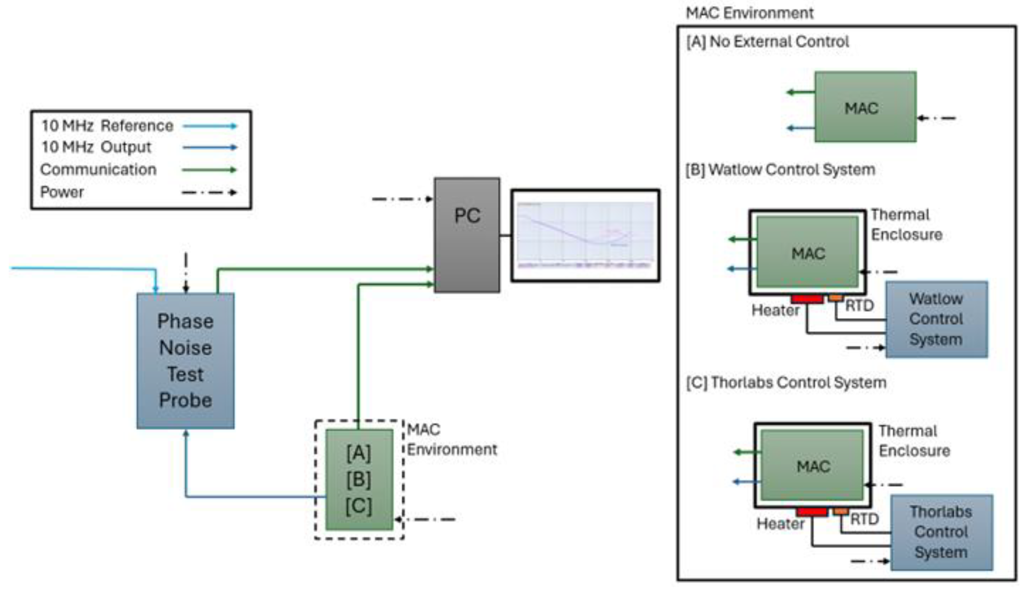
Figure 2.
(a) The CAD model of the thermal enclosure, and (b) the fabricated unit.
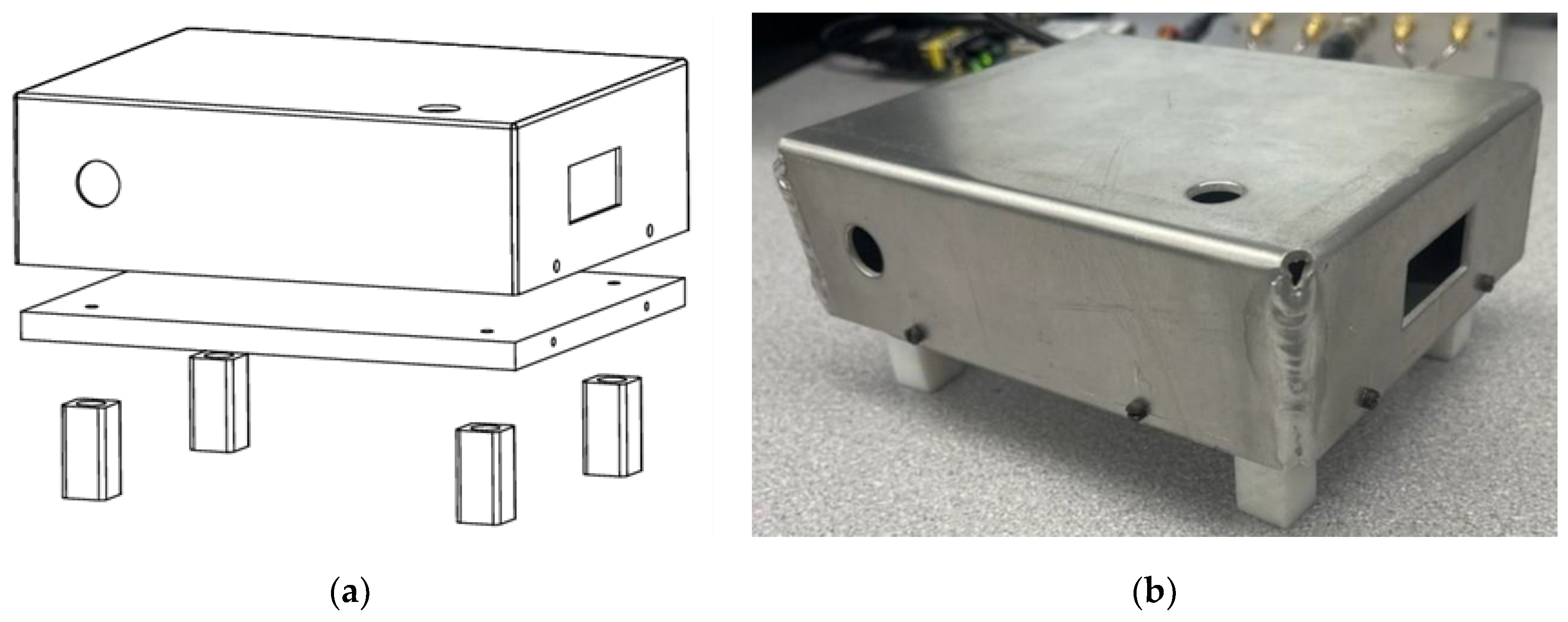
Figure 3.
MAC internal case temperature over 7 days for the ambient characterization (blue), characterization with moderate confinement with the Watlow unit (yellow), and characterization with rigorous confinement with the Thorlabs unit (green).
Figure 3.
MAC internal case temperature over 7 days for the ambient characterization (blue), characterization with moderate confinement with the Watlow unit (yellow), and characterization with rigorous confinement with the Thorlabs unit (green).
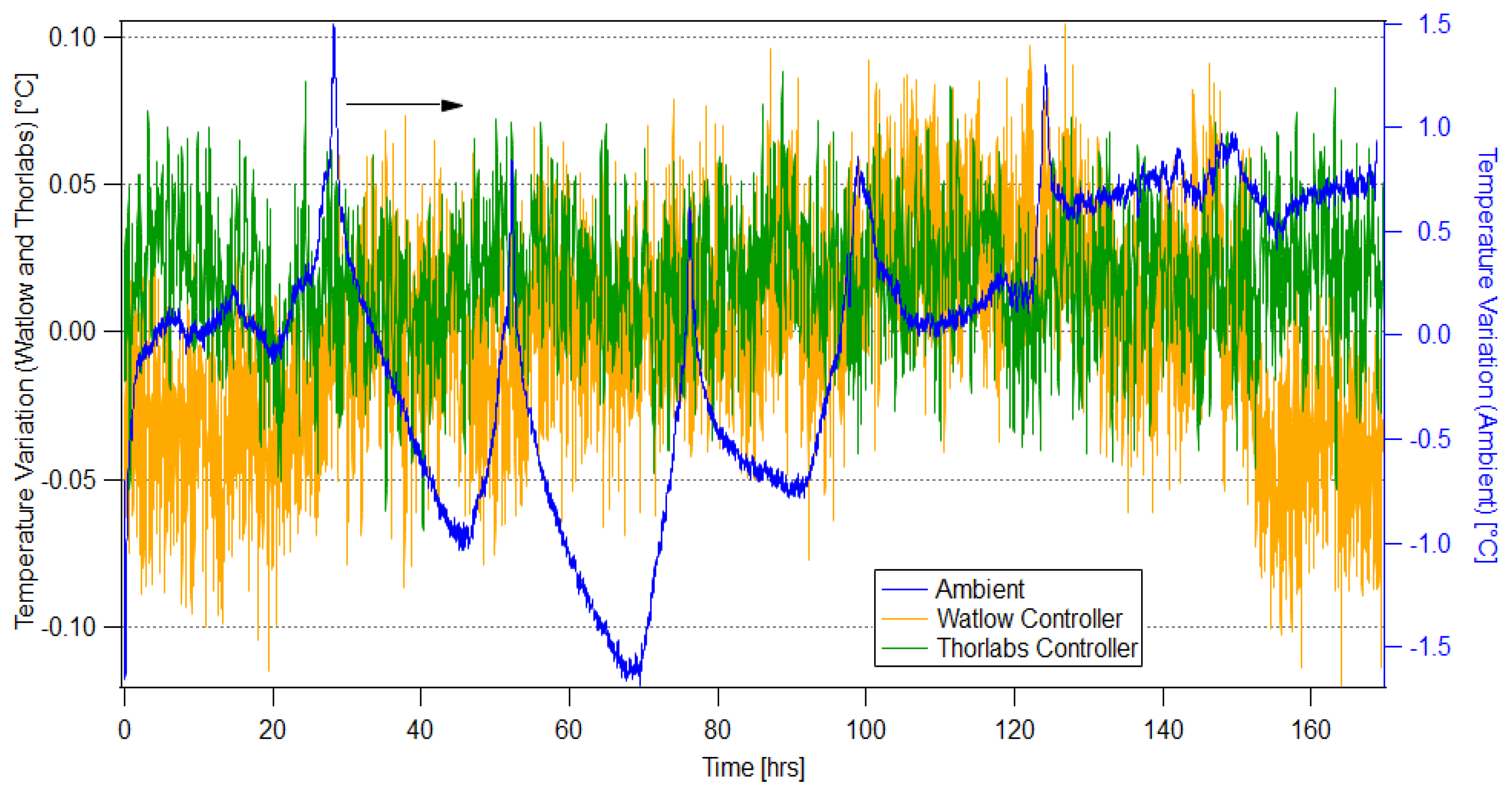
Figure 4.
The stability performance of the MAC for ambient characterization (blue), characterization with moderate confinement with the Watlow unit (yellow), characterization with rigorous confinement with the Thorlabs unit (green), and datasheet values (red).
Figure 4.
The stability performance of the MAC for ambient characterization (blue), characterization with moderate confinement with the Watlow unit (yellow), characterization with rigorous confinement with the Thorlabs unit (green), and datasheet values (red).
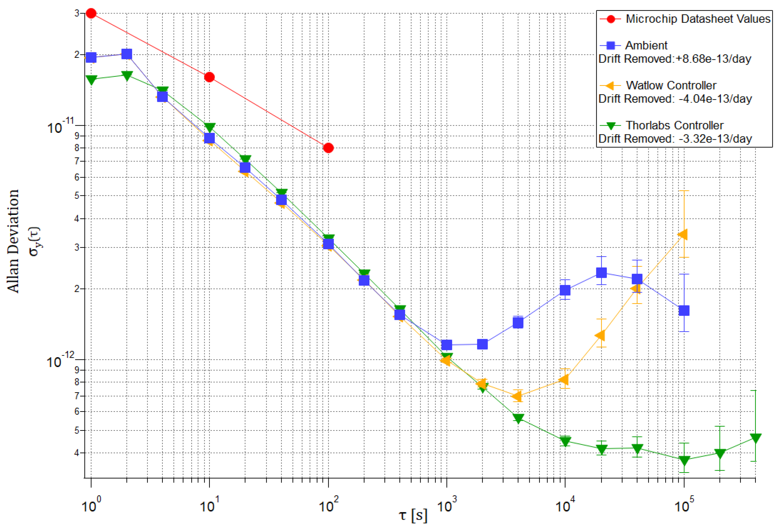

Table 1.
Coefficient for optimum time error prediction [19].
Table 1.
Coefficient for optimum time error prediction [19].
| Noise Type | ADEV Slope | k |
| White & Flicker PM | τ -1 |
|
| White FM | τ -1/2 | 1 |
| Flicker FM | τ 0 |
|
| Random Walk FM | τ 1/2 | 1 |
Table 2.
Comparison of the size, weight, and power parameters, Allan Deviation, and positioning error for the CSAC, MAC, and mRO-50.
Table 2.
Comparison of the size, weight, and power parameters, Allan Deviation, and positioning error for the CSAC, MAC, and mRO-50.
| Clock Type | Size [cm3] | Weight [g] | Power [W] |
Averaging Interval τ [s] |
ADEV | Positioning Error [m] |
| Microchip CSAC SA.45s | 17 | 35 | 0.12 | 10 | 1.00e-10 | 0.30 |
| 102 | 3.00e-11 | 0.90 | ||||
| 103 | 1.00e-11 | 1.78 | ||||
| Microchip MAC SA.35m | 50 | 86 | 5 | 10 | 1.60e-11 | 0.05 |
| 102 | 8.00e-12 | 0.24 | ||||
| 103 | N/A* | - | ||||
| Safran mRO-50 | 50 | 75 | 0.45 | 10 | 3.00e-11 | 0.09 |
| 102 | 1.00e-11 | 0.30 | ||||
| 103 | N/A* | - |
* Tables may have a footer.
Table 3.
Long-term stability performance comparison of the MAC for ambient and enhanced thermal confinement testing.
Table 3.
Long-term stability performance comparison of the MAC for ambient and enhanced thermal confinement testing.
|
MAC SA.35m (averaging time) |
Ambient |
Moderate Thermal Confinement (±0.10°C) [Watlow Controller] |
Rigorous Thermal Confinement (±0.075°C) [Thorlabs Controller] |
| Tau [s] | ADEV | ADEV | ADEV |
| 1.0x10³ | 1.16e-12 | 9.90e-13 | 1.03e-12 |
| 4.0x10³ | 1.44e-12 | 6.98e-13 | 5.66e-13 |
| 1.0x10⁴ | 1.98e-12 | 8.22e-13 | 4.49e-13 |
| 4.0x10⁴ | 2.20e-12 | 2.02e-12 | 4.20e-13 |
Table 4.
Allan Deviation and related positioning error values from the MAC datasheets and individual characterizations of the ambient performance and thermally confined performance.
Table 4.
Allan Deviation and related positioning error values from the MAC datasheets and individual characterizations of the ambient performance and thermally confined performance.
| Model |
Microchip MAC SA.35m |
Microchip MAC SA.57m |
||||||
|
Characterization Conditions |
Datasheet | Ambient† |
Enhanced Thermal Confinement† |
Datasheet | ||||
| Tau [s] | ADEV | Positioning Error [m] | ADEV | Positioning Error [m] | ADEV | Positioning Error [m] | ADEV | Positioning Error [m] |
| 10 102 103 104 105 |
1.60e-11 8.00e-12 N/A* N/A* N/A* |
0.05 0.24 - - - |
8.80e-12 3.12e-12 1.16e-12 1.98e-12 1.62e-12 |
0.03 0.09 0.42 5.94 48.6 |
9.82e-12 3.28e-12 1.03e-12 4.49e-13 3.73e-13 |
0.03 0.10 0.31 1.62 11.2 |
5.00e-12 1.50e-12 5.00e-13 1.50e-12 1.50e-12** |
0.02 0.05 0.19 4.50 45.0 |
† Values taken from individual clock characterization testing. * Values not specified in manufacturer’s datasheet. ** Values not specified in manufacturer’s datasheet, assumed ADEV maintained from τ=104s.
Disclaimer/Publisher’s Note: The statements, opinions and data contained in all publications are solely those of the individual author(s) and contributor(s) and not of MDPI and/or the editor(s). MDPI and/or the editor(s) disclaim responsibility for any injury to people or property resulting from any ideas, methods, instructions or products referred to in the content. |
© 2025 by the authors. Licensee MDPI, Basel, Switzerland. This article is an open access article distributed under the terms and conditions of the Creative Commons Attribution (CC BY) license (http://creativecommons.org/licenses/by/4.0/).
Copyright: This open access article is published under a Creative Commons CC BY 4.0 license, which permit the free download, distribution, and reuse, provided that the author and preprint are cited in any reuse.


