Submitted:
29 June 2025
Posted:
30 June 2025
You are already at the latest version
Abstract
In order to enhance the anti-corrosion property of the epoxy coatings on 7N01 aluminum alloy, cerium nitrate and zeolite particles were incorporated into the bis-(triethoxysilylpropyl)tetrasulfide (BTESPT) silane solution to pretreat the substrate. Scanning electron microscope (SEM), electronic probe microanalyzer (EPMA) were used to characterize microstructure of the composite silane film. The corrosion performances of the epoxy coatings were evaluated by potentiodynamic polarization, electrochemical impedance spectroscopy (EIS) and microstructure of the interfacial region after salt spray tests. The thickness of the composite silane film by 5 % BTESPT doped with 5×10⁻³ M cerium nitrate and 0.5 g/l zeolite particles is about 2.1 μm. The composite silane film can provide active protection to the substrate surface beneath the epoxy coating. It promotes impedance value of the coating at 10-2 Hz by two to three orders of magnitude, and greatly lessens the interfacial region corrosion between the coating and the substrate. This effect can be ascribed to the high barrier effect of the composite silane film and cerium ions releasing from the silane network and the zeolite particles.
Keywords:
Aluminum alloy
; Epoxy coating
; Zeolite
; Cerium nitrate
; Silane
1. Introduction
7N01 aluminum alloy has been widely used in manufacture of components for high-speed trains due to its lightweight, high strength, high fracture toughness and resistance to fatigue, satisfactory welding properties, and excellent extrusion properties [1,2,3]. However, due to its complex chemical composition, numerous intermetallic particles, such as MgZn2 (η phase), AlFeMnSi and Al3Zr, etc. will be formed in the Al matrix. These particles with different electrochemical activities show a high potential difference between them and the surrounding matrix, resulting in galvanic corrosion/localized attack when subjected to the environmental conditions such as temperature, pressure, water, oxygen, and corrosive solution [1,2,3].
Commonly various kinds of protective coatings are adopted to separate surface of the substrates from the corrosion-prone environment to control and prevent the corrosion process. Among them, epoxy-based coatings are widely used as a long-lasting corrosion-resistant coating due to their excellent electrochemical and mechanical properties, making it has outstanding protection to the metal substrates against corrosion by barrier effect to infiltration of corrosive electrolytes onto the metal surface [4,5,6,7].
However, for the epoxy coatings, when the mixture of epoxy and the curing agent like polyamide are applied to the metal surface, the curing agent will be preferentially adsorbed on surface of the metal oxide [8,9,10,11]. In the exposed environments water and the accompanied aggressive media can diffuse rapidly along the interface and accumulate in it, leading to deterioration of the adhesion of epoxy coating to the metal substrate and corrosion of metal surface in the region of reduced adhesion [4,5,8,9,10,11].
Thus in order to promote the long-term durability of the adhesion and the corrosion protection to the metal surface underneath the organic coatings, modification of the interface by surface pretreatment of the metal substrates prior to the coating process is one of the important approaches. During the past decades, several effective methods, including chromate conversion coatings (CCCs), phosphating, anodization, etc., have been made to modify surface of aluminium substrates to strengthen the interface between aluminium and epoxy [4,5,8,9,10,11]. Among these approaches chromate conversion coatings (CCCs) chromating is an effective and widely used approach for surface pretreatment of metal substrates for many years. However, they are banned or strongly restricted due to the hazardous hexavalent chromium compounds.
To this end, van Ooij, et al. pionnered organosilanes as a potential replacement for hexavalent chromating and phosphating pretreatment processes in metals finishing [12,13,14,15,16,17,18]. The silanes of aminopropyltriethoxysilane (APS), tetraethoxysilane (TEOS), methyltriethoxysilane (MTES) and γ-glycidoxypropyltrimethoxysilane (γ-GPS), and several kinds of bis-silanes, such as bis-(trimethoxysilylpropyl)amine (Bis-amino), bis-1,2-(triethoxysilyl)ethane (BTSE) and bis (triethoxysilylpropyl)tetrasulfide (BTESPT), and mixtures of two kinds of silanes as BTESPT/bis-amin and bis-amino/vinyltriacetoxy silane (VTAS), have been used to improve the anti-corrosion property of steels, aluminium alloys, Zn and Zn coated steels, Cu and Cu alloys, etc. [12,13,14,15,16,17,19,20,21,22]. The silane film can strengthen the adhesion bonds between the covering organic coatings and metal substrates and enhance the anti-corrosion ability of the organic coatings on metal substrates [12,13,14,15,16,17,18,19,20,21,22]. Fedel, et al. [23] reported that the corrosion protection properties of the epoxy-polyester powder coating on the galvanized steel by barrier effect against water and oxygen of sol-gel pre-treatment to the substrate with the silane compounds of GPS, TEOS and MTES. Romanoa et al. [24] reported that the barrier properties and filiform corrosion resistance of the cataphoretic epoxy coating on 6016 aluminium alloy was improved by sol-gel pretreatment to the substrate with the silane compounds of GPS, TEOS and MTES. Our previous work [25] showed that the pretreatment to 2A12 aluminum alloy sheet by BTESPT silane is effective to lessen corrosion of the substrate underneath the epoxy coating. These published results show that silane-based pretreatment is a promising technology to replace chromates and phosphates for surface modification and corrosion protection of many metal substrates.
However, the silane films do not have active electrochemical behavior, and the aggressive media can access the interface through the defects, such as micro pores, cracks and low cross-linked zones in the thin silane film [18]. Many efforts have been made to provide the silane film with active self-healing for improvement of the long-term corrosion protection [26,27,28,29,30,31]. Rare earth salts contain Y3+, La3+, Pr3+ and Nd3+ ions, especially Ce3+, are corrosion inhibitors. Therefore incorporation of these rare earth salts into the silane films to improve the corrosion resistance has been attempted [10,11,12]. Baharmi et al. [32] have reported the anti-corrosion property of the Si/Zr sol-gel hybrid coating on 6061 aluminum alloy is improved by doping with cerium nitrate. Cabral, et al. [33] have reported the pre-treatment based on BTESPT solution doped with cerium nitrate has longer lifetime protection to corrosion for dip galvanised steel and AA2024-T3 aluminum alloy. Shi, et al. [34] have reported that the addition of 1×10⁻³ M Ce(NO3)3 into silane solution of GPTMS and TMOS significantly improved the corrosion resistance of the sol-gel coating on 2024-T3 aluminum alloy. Naderi, et al. [27] reported the stability of pure Al interface was improved by incorporation of cerium cations into silane sol-gel coating. Unfortunately, the corrosion inhibitors are prone to be uncontrolled fast leaking [35,36,37,38].
Zeolite particles, microporous cage-structured aluminosilicate crystals, have large amounts of nanoporous channels and high chemical affinity for ion exchange and adsorption and can be used as a reservoir to adsorb a variety of cations including rare earth ions [39]. Dias et al. [35,36] have reported preparation of a sol-gel hybrid coating by doping of cerium-enriched zeolite (NaX) into the hybrid solution of a glycidoxypropyl-trimethoxy-silane (GPTMS) based alkosol and a alkosol containing zirconium tetrapropoxide. The results show that incorporation of cerium ions stored NaX zeolites increases the anti-corrosion performance of the film. Zheludkevich, et al. [37] reported that the sol-gel film of TEOS and GPTMS doped with zirconia nanoparticles and cerium nitrate, or cerium nitrate doped oxide nanoparticles led to improvement of the corrosion protection of AA2024-T3 substrate. The zirconia particles act as nanoreservoirs to prolong release of cerium ions. Urša Tiringer et al. [38] reported that increase of corrosion protection of aluminium alloy 7075-T6 by incorporation of colloidal SiO2 and cerium nitrate to form a GPTMS/TEOS based sol-gel coatings.
In our previous work [40] it has shown that for corrosion protection to 7N01 aluminum sheets the proper bis-[triethoxysilylpropyl]tetrasulfide silane (BTESPT) silane volume is 5% and the optimum cerium nitrate doping in the silane solution is 5×10⁻³ M. Cabral et al. [33] indicated that the silane film, doped with 1×10⁻³ M cerium nitrate in BTESPT solution, on dip galvanised steel and AA2024-T3 aluminum substrates has longer lifetime protection to corrosion.
Therefore, in this work, different contents of zeolite particles were added into 5% silane solution doped with 5×10⁻³ M cerium nitrate to form a composite film on surface of 7N01 aluminum alloy prior to epoxy coating. The work aims to evaluate the corrosion performance of epoxy coatings on 7N01 substrates without and with this pretreatmet. The corrosion properties were assessed by potentiodynamic polarization, electrochemical impedance spectra (EIS), immersion and salt spray tests. Scanning electron microscope (SEM), electronic probe microanalyzer (EPMA) were used to characterize microstructure of the composite silane film and the interfacial region between the epoxy coating and the substrate.
2. Experimental Methods
2.1. Materials and the Coating Process
2.1.1. 7N01 Substrates
The used 7N01 aluminum alloy substrates were rolled sheets with a thickness of 3 mm (wt.: Zn 4.6%, Mg 1.7%, Mn 0.55%, Cu 0.16%, Cr 0.2%, Si 0.2%, Zr 0.15%, balance Al). All the sheet substrates were boiled in boiling water for 20 minutes, polished with SiC paper of grit 320-1500, rinsed by tap water. Then the substrates were immersed in 0.3M NaOH solution for two minutes, cleaned with deionized water and drying at room temperature. Next they were cleaned by ultrasound in ethanol and deionized water for a few minutes, dry in air before used.
2.1.2. Preparation of Silane Solution with Cerium Nitrate and Nano Zeolite Particles
The bis-[triethoxysilylpropyl]tetrasulfide silane ((H5C2O)3Si(CH2)3S4(CH2)3Si(OC2H5)3) solution was prepared by dissolving 5 % (v/v) of the silane in ethanol 90 %(v/v) and deionized water 5 % (v/v), then 5×10⁻³ M cerium nitrate and 0.25 g/L, 0.5 g/L and 2.5 g/L zeolite particles (the average diameter <500 nm) were added into the silane solutions respectively. The mixed silane solutions were stirred for 30 minutes before use.
2.1.3. Preparation of the Composite Silane Film and Top-Coated Epoxy Coating
The substrates were immersed in prepared silane solutions for 3 min and then cured at 120℃for 2 h in blast oven to promote the cross-linking of the composite silane films.
The used epoxy coating is a two components epoxy-polyamide material commercialized by Zhongshan Daoqum Chem. Com., China (epoxy EP160 and polyamide based curing agent A-017 with a weight ratio of 6:1 according to the manufacturer recommendations). The mixture, with an amount of 39 mass% of solvent-mixture (25 vol.% n-butanol and 75 vol.% xylene) was prepared at room temperature (25℃) by stirring for 30 min. The resin mixture was applied on the substrates by spray coating process. The process should be reproducible as much as possible to ensure homogeneous distribution of the coating and a comparable thickness in all samples. The coated samples were allowed to cure for 7 days at room temperature. The thickness of the coating is about 70 μm.
2.2. Characterization
The surface morphologies, microstructure of the different samples were observed by ZEISS and MIRA3 LMH scanning electron microscope (SEM) operated at 20 kV. Energy dispersive X-ray spectroscopy (EDS) analysis was used for the chemical composition. The surface and cross-sectional distribution of typical elements of the samples was performed using the Electron Probe Microanalyzer (JXA-8230).
Soaking tests were carried out in 3.5 wt.% NaCl solution at ambient temperature. Salt spray tests were performed following the standard of ASTM B 117. The coated samples were exposed to 5 wt.% NaCl solution at 35±2℃.
The potentiodynamic polarization and electrochemical impedance spectroscopy (EIS) tests were carried out in 3.5 wt.% NaCl aqueous solution at ambient temperature with a CHI Model 660E electrochemical work station, in a three-electrode system with the sample as the working electrode, a saturated calomel electrode as the reference electrode, and a platinum panel as the counter electrode. The area exposed to the solution of the samples is 1 cm2. The polarization tests were conducted at a scanning rate of 0.002 v/s. The EIS measurements were carried out at the open circuit potential
3. Results and Discussion
3.1. Effect of Zeolite Particles on the Surface Pretreated Substrates
Figure 1 shows surface SEM morphologies of the prepared composite silane films on 7N01 substrates by 5 % BTESPT doped with 5×10⁻³ M cerium nitrate and different contents of zeolite particles. For the case with 0.25 g/l zeolite particles, a lot of white particles can be observed, as shown in Figure 1a). The EDS spectrum of point 29 and the chemical composition in Table 1 show it contains 28.79 wt.% Ce, indicating it is cerium oxides or hydroxides [26,27,30,33,34,35]. In addition, gray particles, marked by 36, can also be found. According to its EDS spectrum and the chemical composition in Table 1, it contains high contents of Si and O, confirming it a zeolite particle doped with Ce. When the zeolite particles increased to 0.5 g/l, a lot of gray particles can be seen in Figure 1b) compared with Figure 1a). They are the zeolite particles doped with Ce (see point 3 in Table 1). When the zeolite particles increased to 2.5 g/l, a great number of gray particles can be seen in Figure 1c). Also they are the zeolite particles doped with Ce (see point 24 in Table 1). However, many agglomerated zeolite particles are aggregated together as shown by magnification in Figure 1c), which will create defects such as micro cracks and voids between the agglomerated zeolite particles [41,42,43].
Figure 2 presents the EPMA surface elemental mapping of the pretreated composite silane film on 7N01 substrate by 5 % BTESPT doped with 5×10⁻³ M cerium nitrate and 0.5 g/l zeolite particles. As for the particles A and B, they contain high Ce and O, indicating they are cerium oxides or hydroxides independently precipitated in the composite silane film [33,34,35]. While for the particles C and D, they contain high O, Si and Ce, indicating they are zeolite particles with Ce adsorbed.
Figure 3 gives cross-sectional morphology of the composite silane film by 5% BTESPT doped with 5×10⁻³ M cerium nitrate and 0.5 g/l zeolite particles and EPMA elemental mapping. The thickness of the composite silane film, determined by Figure 3a), is about 2.1 μm. While for the pure silane films on metal substrates their thickness are below 1 μm, generally around 0.2-0.5 μm [33].
Figure 4 shows surface images of the the pretreated composite silane films on 7N01 substrates by 5 % BTESPT doped with 5×10⁻³ M cerium nitrate and different contents of zeolite particles during immersion in 3.5 wt.% NaCl solution for different time. Our previous work [40] has shown that local corrosion occurred after 28 days immersion for the sample pretreated by the silane film doped with 5×10⁻³ M cerium nitrate. For the sample pretreated by the silane film doped with 5×10⁻³ M cerium nitrate and 0.25 g/l zeolite particles, local corrosion can be observed after 42 days immersion, as shown in Figure 4b), suggesting that addition of zeolite particles improves the corrosion protection of the silane film. When the zeolite particles increases to 0.5 g/l, almost no any change can be observed on surface of the sample even after 60 days immersion, as shown in Figure 4d), demonstrating excellent corrosion protective property of the composite silane film. However, when the zeolite particles increases to 2.5 g/l, obviously local corrosion occurred only after 10 days immersion as shown in Figure 4e), indicating that incorporation of higher zeolite particles into the silane film leads to negative impact on protective property and therefore causes worse corrosion protection. This can be ascribed to aggregation of the agglomerated zeolite particles as shown in Figure 1c), which causes formation of micro defects between the agglomerated zeolite particles [41,42,43]. These defects will favor penetration of the aggressive media through the film and decrease its barrier properties [42,43]. Therefore the following work will focus on corrosion performances of the epoxy coatings on 7N01 substrates without and with pretreatment by 5% BTESPT doped with 5×10⁻³ M cerium nitrate and 0.5 g/l zeolite particles.
3.2. Corrosion Performance of the Epoxy Coated Substrates
Figure 5 shows the cross-sectional morphologies for the sample with epoxy coating on blank 7N01 substrate and the sample with epoxy coating on 7N01 substrate pretreated by the composite silane film doped with 5×10⁻³ M cerium nitrate and 0.5 g/l zeolite particles. It can be seen that both of the interfacial regions are flat without apparent irregularities. No cracks can be observed at the interfacial regions, demonstrating that the adhesion between the epoxy coatings and the substrates are in well adhered state in both cases to endure the mechanical cutting and polishing processes. The thickness of the epoxy coatings on the substrates are measured to be about 70 μm.
3.2.1. Polarization Tests
Figure 6 shows the polarization curves for the samples with epoxy coatings on the blank 7N01 substrates in 3.5 wt.% NaCl solution after different time immersion. The fitted results are listed in Table 2. For the sample with 1 h immersion in 3.5 wt.% NaCl solution, its corrosion potential (Ecorr) is -0.75 V, and the corrosion current density (Icorr) is 1.20×10⁻¹² A/cm2. However, for the sample with 168 h immersion, its Ecorr shifts to -1.15 V, and Icorr increases to 2.83×10⁻⁹ A/cm2, and a pitting point around -0.80 V can be observed. As for the samples with 192, 240 and 288 h immersion, their Ecorr are around -1 V, the pitting points are around -0.87 V, and their Icorr range from 10-9 to 10-8 A/cm2. These demonstrate that 168 h immersion in 3.5 wt.% NaCl solution causes decline of the corrosion protective property of the epoxy coatings on the blank 7N01 substrates, with the measured Ecorr shifts from -0.75 V to about -1.1 V and Icorr increases by 3 orders of magnitude from 10-12 A/cm2 to 10-9 A/cm2.
Figure 7 gives polarization curves for the samples with epoxy coatings on 7N01 substrates pretreated by 5 % BTESPT doped with 5×10⁻³ M cerium nitrate and 0.5 g/l zeolite particles in 3.5 wt.% NaCl solution after different time immersion. The fitted results are listed in Table 3. For the sample with 1 h immersion in 3.5 wt.% NaCl solution, its Ecorr is -0.67 V, and the Icorr is 7.02×10⁻¹³ A/cm2. For the samples with 168 to 288 h immersion, their Ecorr range between -0.76-0.70 V, and Icorr range between 2.78×10⁻¹² to 4.18×10⁻¹² A/cm2. It should be noted that no pitting potential can be observed for all curves. These demonstrate that 168-288 h immersion in 3.5 wt.% NaCl solution causes only a little decline of the corrosion protective property of the epoxy coatings on 7N01 substrates pretreated by 5% BTESPT doped with 5×10⁻³ M cerium nitrate and 0.5 g/l zeolite particles.
3.2.2. EIS Tests
Figure 8 presents the Bode plots of EIS for the sample with epoxy coating on the blank 7N01 substrate in 3.5 wt.% NaCl solution. It can be seen that the impedance spectra for 1 h and 12 h shows very high impedance values (about 1010 Ω·cm2) at 10-2 Hz and high phase angles, suggesting the epoxy coating behave close to a capacitor. However, the impedance value declines rapidly to about 107 Ω·cm2 at 24 h. Then it declines gradually to 1.26×10⁴ Ω·cm2 as the immersion time prolongs to 388 h, demonstrating that the conductive pathways have been developed in the epoxy coating and the aggressive media can penetrate through the pathways to reach the substrate surface. From the phase-frequency plots two time constants can be clearly observed after 24 h immersion. The time constant at high frequency is associated with the barrier property of the epoxy coating, and the second one at medium frequency (10-1-102 Hz) can be ascribed to the substrate surface oxide film and the interfacial layer between the epoxy and the substrate. It should be noted that for the plots of 96 h and 388 h, an inductive behavior at the lowest frequency can be observed, suggesting occurring of corrosion activity by the aggressive media to surface of the substrate.
Figure 9 presents the Bode plots of EIS for the sample with epoxy coating on 7N01 substrate pretreated by 5 % BTESPT doped with 5×10⁻³ M cerium nitrate and 0.5 g/l zeolite particles in 3.5 wt.% NaCl solution. It can be seen that for 1 h and 12 h the impedance values at 10-2 Hz are about 1010 Ω·cm2. For the spectrum at 24 h the impedance value at 10-2 Hz declines rapidly to about 107 Ω·cm2, which is almost the same as that in Figure 8. This means that the conductive pathways have been developed in the epoxy coating and thus the aggressive media can penetrate through the pathways to reach the composite silane film. For the spectra at 24 h and the following immersion times two time constants can be observed. The time constant at high frequency is attributed to the barrier property of the epoxy coating, and the second one at medium frequency (10-1-102 Hz) can be ascribed to the composite silane film doped with cerium nitrate and zeolite particles. At 48 h the impedance value at 10-2 Hz increases, by more than one order of magnitude, to 2×10⁸ Ω·cm2, which can be ascribed to the barrier property of the composite silane film, especially the action of the doped cerium nitrate and zeolite particles in the film. At 96 h the impedance value at 10-2 Hz decreases to 1.5×10⁷ Ω·cm2, and the phase angle at the lowest frequency increases like that at 24 h, also suggesting reactions of the aggressive media to the composite silane film. From 168 h to 388 h, the impedance value at 10-2 Hz remains stable at about 6.2×10⁷ Ω·cm2, which is more than two to three orders of magnitude higher than that of the corresponding spectra in Figure 8, suggesting no corrosion occur to the substrate surface.
3.3. Interfacial Microstructure Between Epoxy Coating and Al Substrate After Salt Spray Test
The samples with epoxy coatings after salt spray test for 30 and 60 days were cut and slightly polished to examine the interface between the epoxy coating and 7N01 substrate. Figure 10 presents the cross-sectional morphologies for the sample with epoxy coating on blank 7N01 substrate and the results of EDS analysis after 30 days salt spray test. Compared to the flat shape without irregularities in Figure 5, 30 days salt spray test changes the interfacial region into apparent irregularity. The results of EDS analysis in the marked region demonstrate that the dark area, the upper part of the marked region, contains relatively low concentration of Al and high amount of O. According to the EIS in Figure 8, at 24 h the aggressive media has penetrated through the developed pathways in epoxy coating to reach at the substrate surface, and after 24 h the impedance value at 10-2 Hz declines gradually to 104 Ω·cm2 due to corrosion of the substrate surface by the aggressive media. Therefore, the dark area could be ascribed to the corrosion activity caused by the aggressive media penetrated through epoxy coating to the substrate surface.
Figure 11 presents the cross-sectional morphologies for the sample with epoxy coating on blank 7N01 substrate and the results of EDS analysis after 60 days salt spray test. It can be seen that after 60 days salt spray test the interfacial region is also in irregularity. The results of EDS analysis in the marked region demonstrate that the gray area, the upper part of the marked region, contains relatively low concentration of Al and high amount of O, which is caused by corrosion activity of the aggressive media to the substrate surface. It should be noted that there is a long crack between the epoxy coating and the substrate, which takes the shape of zig-zag. During the salt spray test the water transports through the epoxy coating to reach the interfacial region, which will cause breaking of Al-O bond and localized dissolution of the oxide layer, then induce passage of ions such as hydroxyl, oxygen and chlorine ions inwards and aluminium ions outwards [4,5,6,7,25]. Considering its shape and the EDS mapping of Al and O in the marked area, it could be concluded that the crack is located in the oxide layer formed during the spray salt process underneath the epoxy coating. These features indicate that the substrate endures more severe corrosion after 60 days test than that of 30 days test as shown in Figure 10.
Figure 12 presents the cross-sectional morphologies for the sample with epoxy coating on 7N01 substrate pretreated by the composite silane film doped with 5×10⁻³ M cerium nitrate and 0.5 g/l zeolite particles after 30 days salt spray test. It can be seen that the interfacial region is still in flat state without apparent irregularities as that of in Figure 5, demonstrating that almost no corrosion occurs to surface of the substrate. According to the EIS in Figure 9, although at 24 h the aggressive media can penetrate through the developed pathways in epoxy coating to reach the composite silane film, the impedance value at 10-2 Hz after 24 h still remains above 107 Ω·cm2. Therefore, it could be concluded it is the composite silane film that avoids penetration of water, oxygen and chloride ions through the film to act on the underneath substrate surface.
Figure 13 presents the cross-sectional morphologies for the sample with epoxy coating on 7N01 substrate pretreated by the composite silane film doped with 5×10⁻³ M cerium nitrate and 0.5 g/l zeolite particles and the results of EDS analysis after 60 days salt spray test. Compared to the flat shape in Figure 12, 60 days salt spray test changes the interfacial region into apparent irregularity. However, no obviously crack like that in Figure 11 can be observed. At the interfacial region, an marked area as shown in Figure 13 b) is selected for EDS analysis. The left upper corner of the marked area is dark, which is the newly formed interfacial region by corrosion activity of aggressive media to the Al substrate. The results of EDS analysis demonstrate it contains high amount of O, Si, S, Ce and low concentration of Al. Elements of S and Ce come from the composite silane film doped with cerium nitrate and zeolite particles, indicating that there is an amount of S especially Ce distributed in the newly formed interfacial region by corrosion activity. This is different to the case for epoxy coating on blank 7N01 substrate as shown in Figure 10 and Figure 11, where there is only the corrosion products by actions of hydroxyl, oxygen and chlorine ions to the Al substrate. During the salt spray test the water, oxygen and chlorine ions reached at the interfacial region through the developed pathways in the epoxy coating will diffuse along the interface and lead to growth of the oxide layer and thus severe corrosion to the substrate surface. While for the case with epoxy coating on 7N01 substrate pretreated by the composite silane film doped with cerium nitrate and zeolite particles, first the water, oxygen and chlorine ions transported through pathways in the epoxy coating are difficult to reach at the interfacial region between the composite silane film and the substrate due to the high barrier effect of the composite silane film, second the aggressive media, penetrated through the composite silane film, are accompanied by cerium ions releasing from the silane network and the zeolite particles, which can provide efficiently active protection to the corrosion zones by forming cerium oxide or hydroxide [33,34,35,36,37,38,42]. Therefore the substrate surface pretreated by the composite silane film endures much slight corrosion during the salt spray test.
4. Conclusions
- (1)
- For the samples with epoxy coatings on the blank 7N01 substrates, 288 h immersion in 3.5 wt% NaCl solution causes Icorr increases from 10-12 A/cm2 to 10-8 A/cm2, while for the samples with epoxy coatings on the 7N01 substrates pretreated by 5 % BTESPT doped with 5×10⁻³ M cerium nitrate and 0.5 g/l zeolite particles 288 h immersion causes only a little increase of Icorr from 10-13 A/cm2 to 10-12 A/cm2.
- (2)
- For the samples with epoxy coatings on the blank 7N01 substrates, 388 h immersion causes the impedance values at 10-2 Hz declines rapidly from 1010 Ω·cm2 to 1.26×10⁴ Ω·cm2. While for the 7N01 substrates pretreated by 5 % BTESPT doped with 5×10⁻³ M cerium nitrate and 0.5 g/l zeolite particles the impedance value at 10-2 Hz remains above 107 Ω·cm2, more than two to three orders of magnitude higher than the former.
- (3)
- The composite silane film greatly lessens the interfacial region corrosion between the coating and the substrate. For the samples with epoxy coatings on the blank 7N01 substrates, salt spray test of 30 and 60 days causes the interfacial region from flat into apparent irregularity, and appearance of crack due to severe corrosion activity. While for the substrate pretreated by the composite silane film it endures only slight corrosion.
- (4)
- The thickness of the composite silane film by 5 % BTESPT doped with 5×10⁻³ M cerium nitrate and 0.5 g/l zeolite particles is about 2.1 μm. Cerium ions are located in the silane film and zeolite particles. The high barrier effect of the composite silane film, and cerium ions releasing from the silane network and the zeolite particles provide active protection to the substrate surface beneath the epoxy coating.
Author Contributions
Lin Sun: Conceptualization, Project administration, Writing-original draft, Formal analysis. Sha Peng: Investigation, Writing-original draft. Han Wang: Investigation,Writing-original draft. Xinyu Lv: Supervision. Jianguo Tang: Conceptualization, Writing-review & editing. Ming-an Chen: Conceptualization, Funding acquisition, Supervision.
Acknowledgments
The authors would like to thank the support from the National Key Research and Development Program of China with grant number of 2017YFB0306301.
Conflicts of Interest
The authors declare that they have no known competing financial interests or personal relationships that could have appeared to influence the work reported in this paper.
References
- Li, B.; Wang, X.; Chen, H.; Hu, J.; Huang, C.; Gou, G. Influence of heat treatment on the strength and fracture toughness of 7N01 aluminum alloy. J. Alloys Compd. 2016, 678, 160–166. [Google Scholar] [CrossRef]
- Wang, S.; Luo, B.; Bai, Z.; He, C.; Jiang, G. Effect of pre-ageing on nucleating of GP zones and precipitation, strength and stress corrosion properties of 7N01 alloy. J. Alloys Compd. 2024, 980, 173681. [Google Scholar] [CrossRef]
- Qin, C.; Gou, G.Q.; Che, X.L.; Chen, H.; Chen, J.; Li, P.; Gao, W. Effect of composition on tensile properties and fracture toughness of Al-Zn-Mg alloy (A7N01S-T5) used in high speed trains. Mater. Des. 2016, 91, 278–285. [Google Scholar] [CrossRef]
- van den Brand, J.; Van Gils, S.; Beentjes, P.C.J.; Terryn, H.; Sivel, V.; de Wit, J.H.W. Improving the adhesion between epoxy coatings and aluminium substrates. Prog. Org. Coat. 2004, 51, 339–350. [Google Scholar] [CrossRef]
- van den Brand, J.; Van Gils, S.; Terryna, H.; Sivel, V.G.M.; de Wit, J.H.W. Changes in epoxy-coated aluminium due to exposure to water. Prog. Org. Coat. 2004, 51, 351–364. [Google Scholar] [CrossRef]
- Anwar, S.; Li, X. A review of high-quality epoxy resins for corrosion-resistant applications. J. Coat. Technol. Res. 2024, 21, 461–480. [Google Scholar] [CrossRef]
- Pessoa, M.O.; Freitas, B.R.; de O, J.; Santos, S.L.B.S.; da Silva, B.P.; Capelossi, V.R.; Cotting, F. Anticorrosion and adhesion performance of a monolayer and double layer silane-epoxy coating systems applied on carbon steel. Surf. Coat. Technol. 2024, 485, 130909. [Google Scholar] [CrossRef]
- Hong, S.G.; Cave, N.G.; Boerio, F.J. Modification of epoxy/metal interphases by adsorbed contaminants. J. Adhesion 1992, 36, 265–279. [Google Scholar] [CrossRef]
- Boerio, F.J.; Hong, P.P. Non-destructive characterization of epoxy-dicyandiamide interphases using surface-enhanced Raman scattering. Mater. Sci. Eng. A 1990, 126, 245–252. [Google Scholar] [CrossRef]
- van Ooij, W.J.; Sabata, A.; Appelhans, A.D. Application of surface analysis techniques to the study of paint/metal interfaces related to adhesion and corrosion performance. Surf. Interface Anal. 1991, 17, 403–420. [Google Scholar] [CrossRef]
- Nakamae, K.; Airu, X.; Asaoka, S. Localization of the curing agent at an epoxy resin/oxidized aluminium interface. Int. J. Adhes. Adhes. 1995, 15, 15–20. [Google Scholar] [CrossRef]
- Van Ooij, W.J.; Zhu, D.; Stacy, M.; Seth, A.; Mugada, T.; Gandhi, J.; Puomi, P. Corrosion Protection Properties of Organofunctional Silanes - An Overview. Tsinghua Sci. Technol. 2005, 10, 639–664. [Google Scholar] [CrossRef]
- Zhu, D.; van Ooij, W.J. Enhanced corrosion resistance of AA 2024-T3 and hot-dip galvanized steel using a mixture of bis-[triethoxysilylpropyl]tetrasulfide and bis-[trimethoxysilylpropyl]amine, Electrochim. Acta 2004, 49, 1113–1125. [Google Scholar] [CrossRef]
- Zhu, D.; van Ooij, W.J. Corrosion protection of AA 2024-T3 by bis-[3-(triethoxysilyl)propyl]tetrasulfide in sodium chloride solution. Part 2: mechanism for corrosion protection. Corros. Sci. 2003, 45, 2177–2197. [Google Scholar] [CrossRef]
- Zhu, D.; van Ooij, W.J. Corrosion protection of AA 2024-T3 by bis-[3-(triethoxysilyl)propyl]tetrasulfide in neutral sodium chloride solution. Part 1: corrosion of AA 2024-T3. Corros. Sci. 2003, 45, 2163–2175. [Google Scholar]
- van Ooij, W.J.; Zhu, D.Q. Electrochemical impedance spectroscopy of bis-[triethoxysilypropyl]tetrasulfide on Al 2024-T3 substrates. Corrosion 2001, 57, 413–427. [Google Scholar] [CrossRef]
- Song, J.; van Ooij, W.J. Bonding and corrosion protection mechanisms of γ-APS and BTSE silane films on aluminum substrates. J. Adhes. Sci. Technol. 2003, 17, 2191–2221. [Google Scholar] [CrossRef]
- Pluddeman, E.P. Silane Coupling Agents, 2nd ed.; Plenum Press: New York, 1990. [Google Scholar]
- Montemor, M.F.; Rosqvist, A.; Fagerholm, H.; Ferreira, M.G.S. The early corrosion behaviour of hot dip galvanised steel pre-treated with bis-1,2-(triethoxysilyl)ethane. Prog. Org. Coat. 2004, 51, 188–194. [Google Scholar] [CrossRef]
- Cabral, A.M.; Duarte, R.G.; Montemor, M.F.; Zheludkevich, M.L.; Ferreira, M.G.S. Analytical characterisation and corrosion behaviour of bis-[triethoxysilylpropyl]tetrasulphide pre-treated AA2024-T3. Corros. Sci. 2005, 47, 869–881. [Google Scholar] [CrossRef]
- Trabelsi, W.; Triki, E.; Dhouibi, L.; Ferreira, M.G.S.; Zheludkevich, M.L.; Montemor, M.F. The use of pre-treatments based on doped silane solutions for improved corrosion resistance of galvanised steel substrates. Surf. Coat. Technol. 2006, 200, 4240–4250. [Google Scholar] [CrossRef]
- Cabral, A.M.; Duarte, R.G.; Montemor, M.F.; Ferreira, M.G.S. A comparative study on the corrosion resistance of AA2024-T3 substrates pre-treated with different silane solutions- Composition of the films formed. Prog. Org. Coat. 2005, 54, 322–331. [Google Scholar] [CrossRef]
- Fedel, M.; Olivier, M.-G.; Poelman, M.; Deflorian, F.; Rossi, S.; Druart, M.-E. Corrosion protection properties of silane pre-treated powder coated galvanized steel. Prog. Org. Coat. 2009, 66, 118–128. [Google Scholar] [CrossRef]
- Romanoa, A.; Fedel, M.; Deflorian, F.; Olivier, M. Silane sol-gel film as pretreatment for improvement of barrier properties and filiform corrosion resistance of 6016 aluminium alloy covered by cataphoretic coating. Prog. Org. Coat. 2011, 72, 695–702. [Google Scholar] [CrossRef]
- Chen, M.A.; Xie, X.; Zhang, X.M. Interactions of BTESPT silane and maleic anhydride grafted polypropylene with epoxy and application to improve adhesive durability between epoxy and aluminium sheet. Prog. Org. Coat. 2009, 66, 40–51. [Google Scholar] [CrossRef]
- Palanivel, V.; Huang, Y.; Van Ooij, W.J. Effects of addition of corrosion inhibitors to silane films on the performance of AA2024-T3 in a 0.5 M NaCl solution. Prog. Org. Coat. 2005, 53, 153–168. [Google Scholar] [CrossRef]
- Naderi, R.; Fedel, M.; Deflorian, F.; Poelman, M.; Olivier, M. Synergistic effect of clay nanoparticles and cerium component on the corrosion behavior of eco-friendly silane sol-gel layer applied on pure aluminum. Surf. Coat. Technol. 2013, 224, 93–100. [Google Scholar] [CrossRef]
- Tian, Z.; Shi, H.; Liu, F.; Xu, S.; Han, E.H. Inhibiting effect of 8-hydroxyquinoline on the corrosion of silane-based sol-gel coatings on AA 2024-T3. Prog. Org. Coat. 2015, 82, 81–90. [Google Scholar] [CrossRef]
- Alinejad, S.; Naderi, R.; Mahdavian, M. The effect of zinc cation on the anticorrosion behavior of an eco-friendly silane sol-gel coating applied on mild steel. Prog. Org. Coat. 2016, 101, 142–148. [Google Scholar] [CrossRef]
- Trabelsi, W.; Cecilio, P.; Ferreira, M.G.S.; Montemor, M.F. Electrochemical assessment of the self-healing properties of Ce-doped silane solutions for the pre-treatment of galvanised steel substrates. Prog. Org. Coat. 2005, 54, 276–284. [Google Scholar] [CrossRef]
- Nikpour, S.; Naderi, R.; Mahdavai, M. Synergistic effect of mentha longifolia and zinc cations in silane primer coating to improve protection properties of the subsequent epoxy coating. Prog. Org. Coat. 2019, 127, 55–69. [Google Scholar] [CrossRef]
- Bahrami, M.; Borhani, G.H.; Bakhshi, S.R.; Ghasemi, A. Optimization of effective processing parameters of hybrid anti-corrosion Si/Zr sol-gel coatings doped with cerium salt for aluminum alloy 6061. J. Sol-Gel Sci. Technol. 2017, 81, 921–933. [Google Scholar] [CrossRef]
- Cabral, A.M.; Trabelsi, W.; Serra, R.; Montemor, M.F.; Zheludkevich, M.L.; Ferreira, M.G.S. The corrosion resistance of hot dip galvanised steel and AA2024-T3 pre-treated with bis-[triethoxysilylpropyl] tetrasulfide solutions doped with Ce(NO3)3. Corros. Sci. 2006, 48, 3740–3758. [Google Scholar] [CrossRef]
- Shi, H.; Liu, F.; Han, E. Corrosion behaviour of sol-gel coatings doped with cerium salts on 2024-T3 aluminum alloy. Mater. Chem. Phys. 2010, 124, 291–297. [Google Scholar] [CrossRef]
- Dias, S.A.S.; Marques, A.; Lamaka, S.V.; Simoes, A.; Diamantino, T.C.; Ferreira, M.G.S. The role of Ce(III)-enriched zeolites on the corrosion protection of AA2024-T3. Electrochim. Acta 2013, 112, 549–556. [Google Scholar] [CrossRef]
- Dias, S.A.S.; Lamaka, S.V.; Nogueira, C.A.; Diamantino, T.C.; Ferreira, M.G.S. Sol-gel coatings modified with zeolite fillers for active corrosion protection of AA2024. Corros. Sci. 2012, 62, 153–162. [Google Scholar] [CrossRef]
- Zheludkevich, M.L.; Serra, R.; Montemor, M.F.; Yasakau, K.A.; Salvado, I.M.M.; Ferreira, M.G.S. Nanostructured sol-gel coatings doped with cerium nitrate as pre-treatments for AA2024-T3 Corrosion protection performance. Electrochim. Acta 2005, 51, 208–217. [Google Scholar] [CrossRef]
- Tiringer, U.; Milošev, I.; Durán, A.; Castro, Y. Hybrid sol-gel coatings based on GPTMS/TEOS containing colloidal SiO2 and cerium nitrate for increasing corrosion protection of aluminium alloy 7075-T6. J. Sol-Gel Sci. Technol. 2018, 85, 546–557. [Google Scholar] [CrossRef]
- Kawai, T.; Tsutsumi, K. Reactivity of silanol groups on zeolite surfaces. Colloid Polym. Sci. 1998, 276, 992–998. [Google Scholar] [CrossRef]
- Peng, S.; Sun, L.; Lin, H.Q.; Deng, Y.L.; Chen, M.A. Preparation and corrosion performance of silane/Ce films on 7N01 aluminum alloy, High Performance Structural Materials, Y. Han (ed.), Springer Nature Singapore Pte Ltd. 2018, pp: 255-267.
- Calabrese, L.; Bonaccorsi, L.; Proverbio, E. Corrosion protection of aluminum 6061 in NaCl solution by silane-zeolite composite coatings. J. Coat. Technol. 2012, 9, 597–607. [Google Scholar] [CrossRef]
- Montemor, M.F.; Ferreira, M.G.S. Analytical characterization of silane films modified with cerium activated nanoparticles and its relation with the corrosion protection of galvanised steel substrates. Prog. Org. Coat. 2008, 63, 330–337. [Google Scholar] [CrossRef]
- Palanivel, V.; Zhu, D.; van Ooij, W.J. Nanoparticle-Filled Silane Films as Chromate Replacements for Aluminum Alloys. Prog. Org. Coat. 2003, 47, 384–392. [Google Scholar] [CrossRef]
Figure 1.
Surface SEM morphologies of the composite silane films by 5% BTESPT doped with 5×10⁻³ M cerium nitrate and different contents of zeolite particles, a) 0.25 g/l, b) 0.5 g/l and c) 2.5 g/l and the EDS spectra of the points.
Figure 1.
Surface SEM morphologies of the composite silane films by 5% BTESPT doped with 5×10⁻³ M cerium nitrate and different contents of zeolite particles, a) 0.25 g/l, b) 0.5 g/l and c) 2.5 g/l and the EDS spectra of the points.
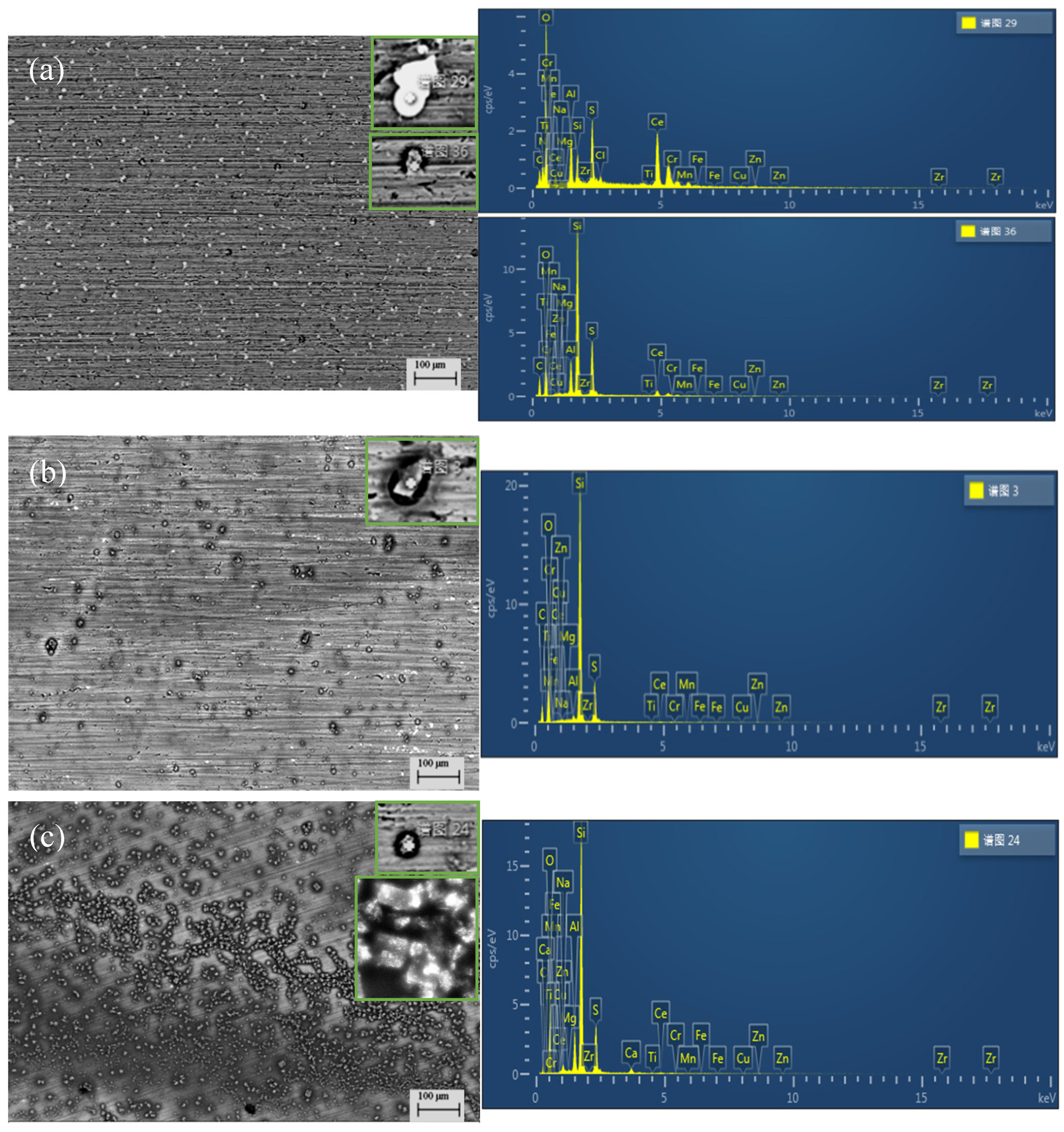
Figure 2.
Surface mapping of the composite silane film by 5 % BTESPT doped with 5×10⁻³ M cerium nitrate and 0.5 g/l zeolite particles.
Figure 2.
Surface mapping of the composite silane film by 5 % BTESPT doped with 5×10⁻³ M cerium nitrate and 0.5 g/l zeolite particles.
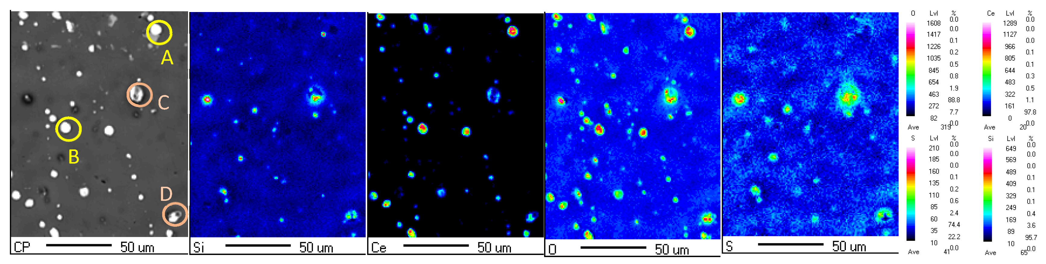
Figure 3.
a) Cross-sectional morphology of the composite silane film by 5 % BTESPT doped with 5×10⁻³M cerium nitrate and 0.5 g/l zeolite particles and b) EPMA elemental mapping.
Figure 3.
a) Cross-sectional morphology of the composite silane film by 5 % BTESPT doped with 5×10⁻³M cerium nitrate and 0.5 g/l zeolite particles and b) EPMA elemental mapping.
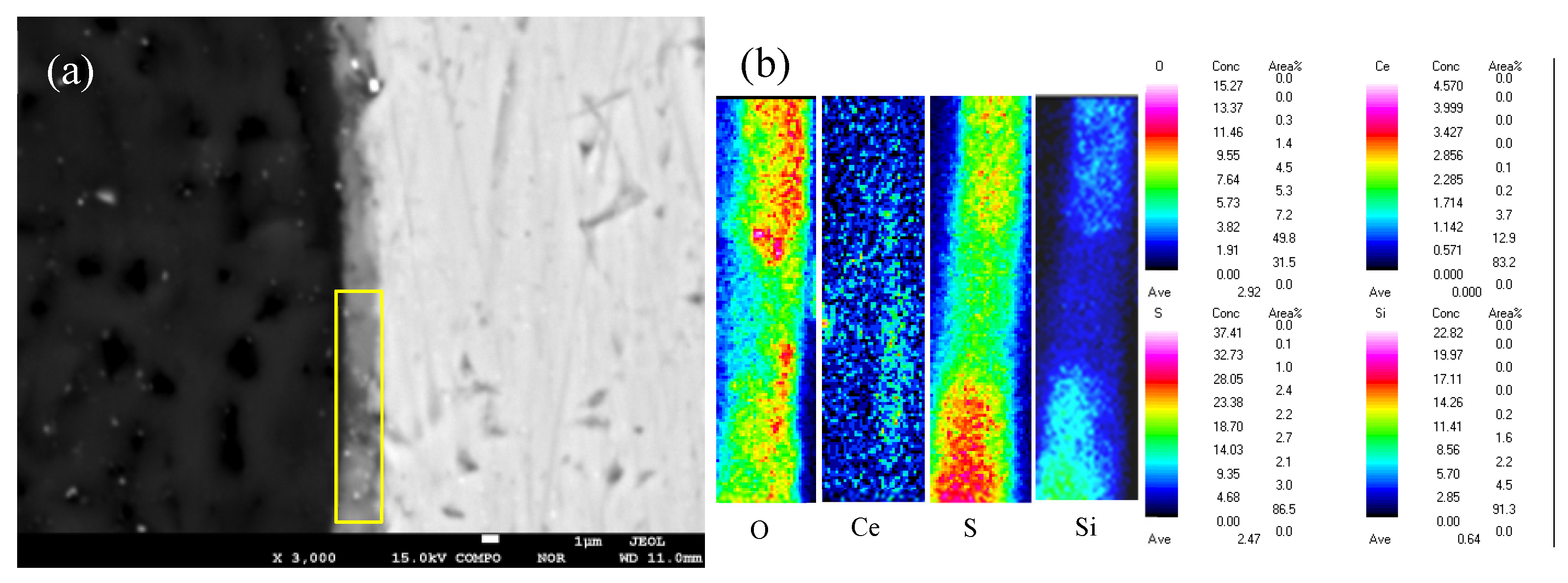
Figure 4.
Surface images of the silane films by 5% BTESPT doped with 5×10⁻³ M cerium nitrate and different contents of zeolite particles during immersion in 3.5 wt% NaCl solution, a-b) 0.25 g/l, c-d) 0.5 g/l and e-f) 2.5 g/l.
Figure 4.
Surface images of the silane films by 5% BTESPT doped with 5×10⁻³ M cerium nitrate and different contents of zeolite particles during immersion in 3.5 wt% NaCl solution, a-b) 0.25 g/l, c-d) 0.5 g/l and e-f) 2.5 g/l.
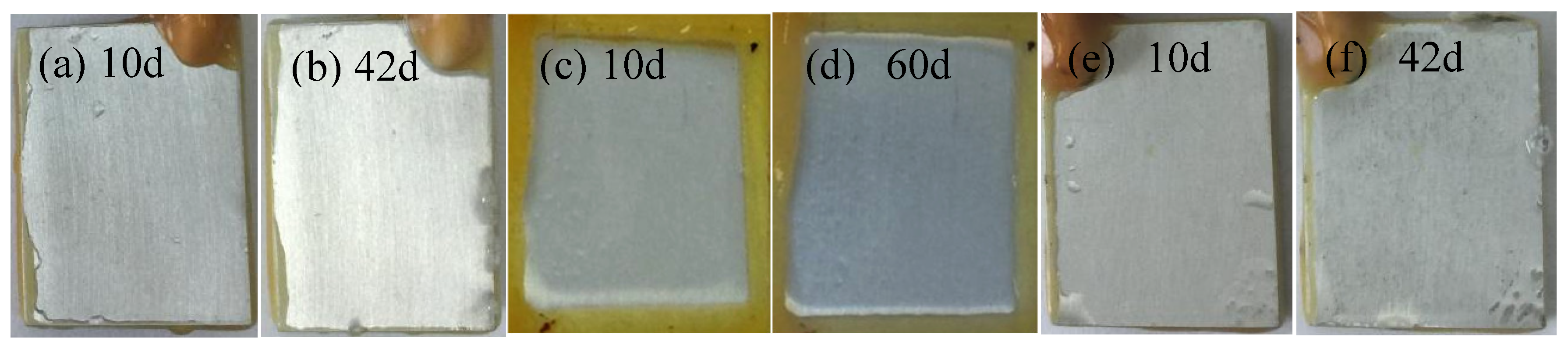
Figure 5.
Cross-sectional morphologies for the samples with epoxy coating on a) 7N01 substrate and b) the 7N01 substrate pretreated by the silane film doped with 5×10⁻³ M cerium nitrate and 0.5 g/l zeolite particles.
Figure 5.
Cross-sectional morphologies for the samples with epoxy coating on a) 7N01 substrate and b) the 7N01 substrate pretreated by the silane film doped with 5×10⁻³ M cerium nitrate and 0.5 g/l zeolite particles.
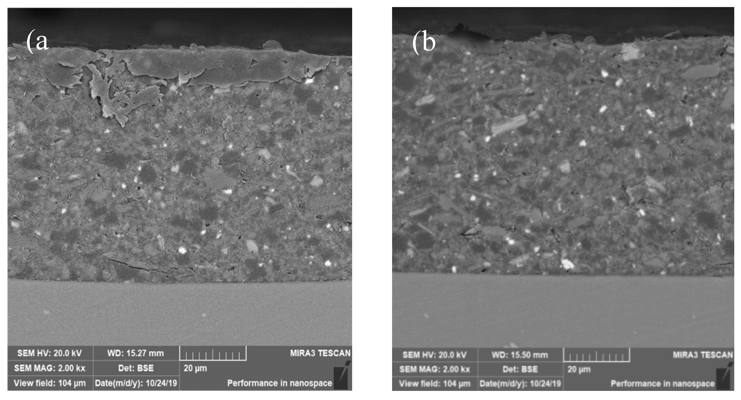
Figure 6.
Polarization curves for the samples with epoxy coatings on the blank 7N01 substrates in 3.5 wt.% NaCl solution after different time immersion.
Figure 6.
Polarization curves for the samples with epoxy coatings on the blank 7N01 substrates in 3.5 wt.% NaCl solution after different time immersion.
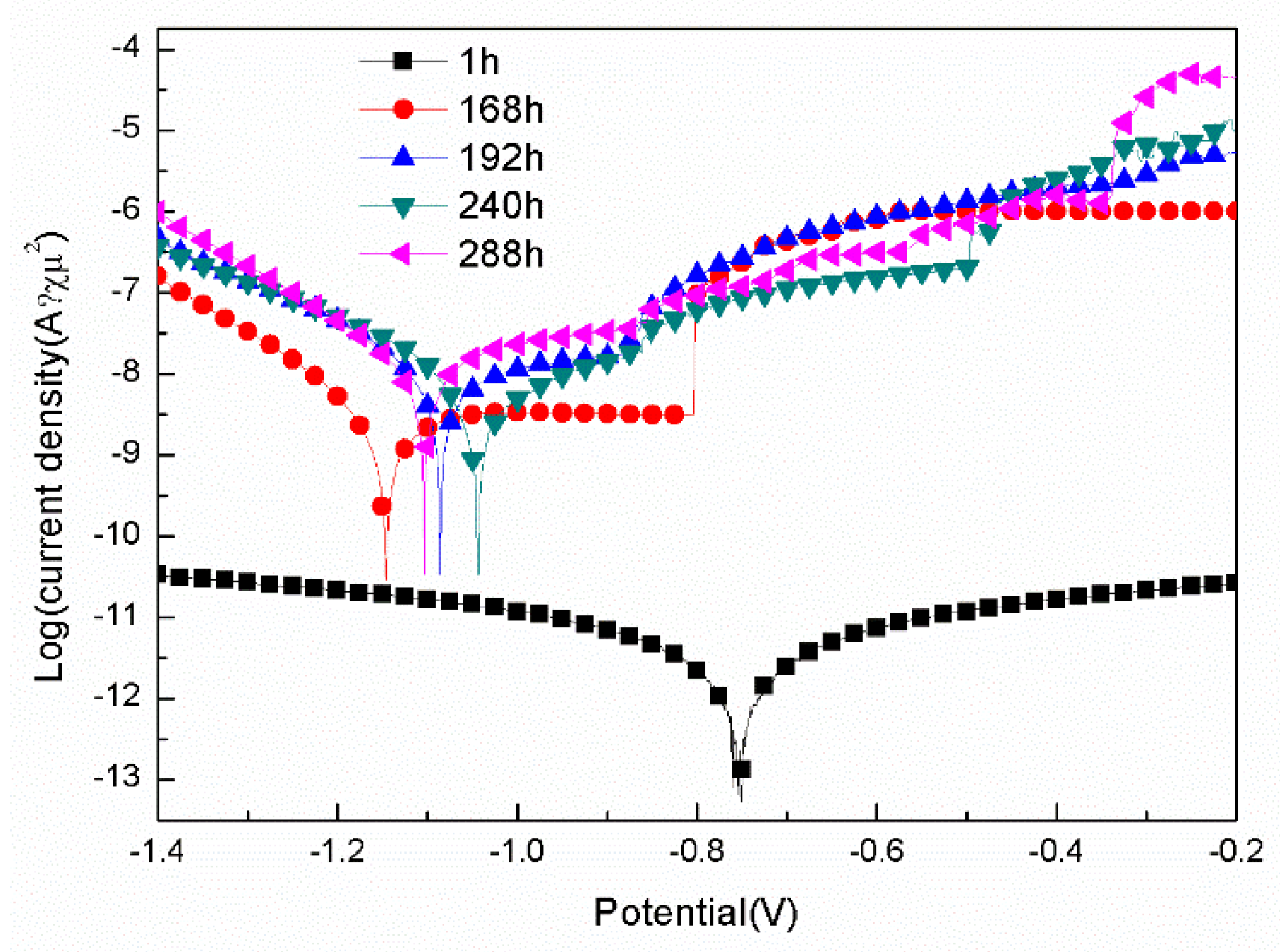
Figure 7.
Polarization curves for the samples with epoxy coatings on 7N01 substrates pretreated by 5 % BTESPT doped with 5×10⁻³ M cerium nitrate and 0.5 g/l zeolite particles in 3.5 wt.% NaCl solution after different time immersion.
Figure 7.
Polarization curves for the samples with epoxy coatings on 7N01 substrates pretreated by 5 % BTESPT doped with 5×10⁻³ M cerium nitrate and 0.5 g/l zeolite particles in 3.5 wt.% NaCl solution after different time immersion.
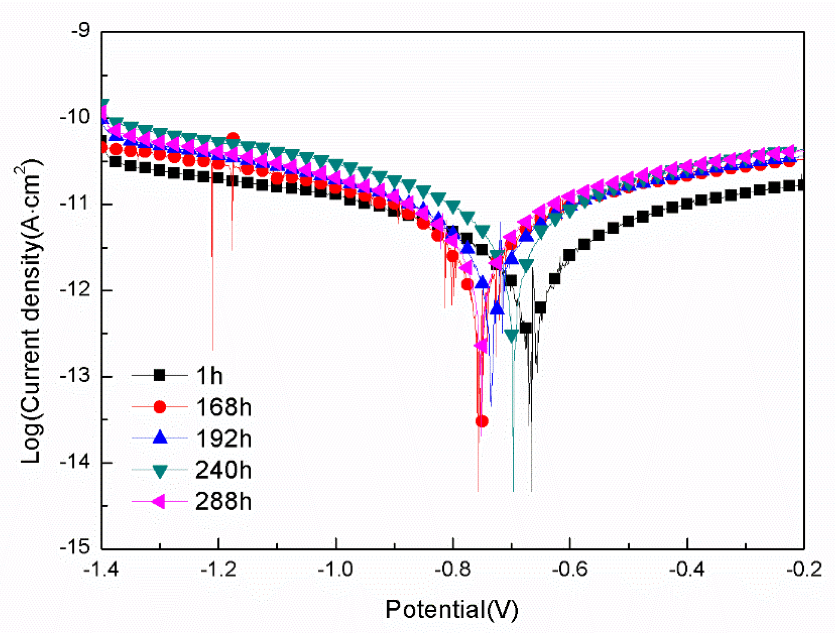
Figure 8.
Bode plots of EIS for the sample with epoxy coating on the blank 7N01 substrate in 3.5 wt.% NaCl solution.
Figure 8.
Bode plots of EIS for the sample with epoxy coating on the blank 7N01 substrate in 3.5 wt.% NaCl solution.
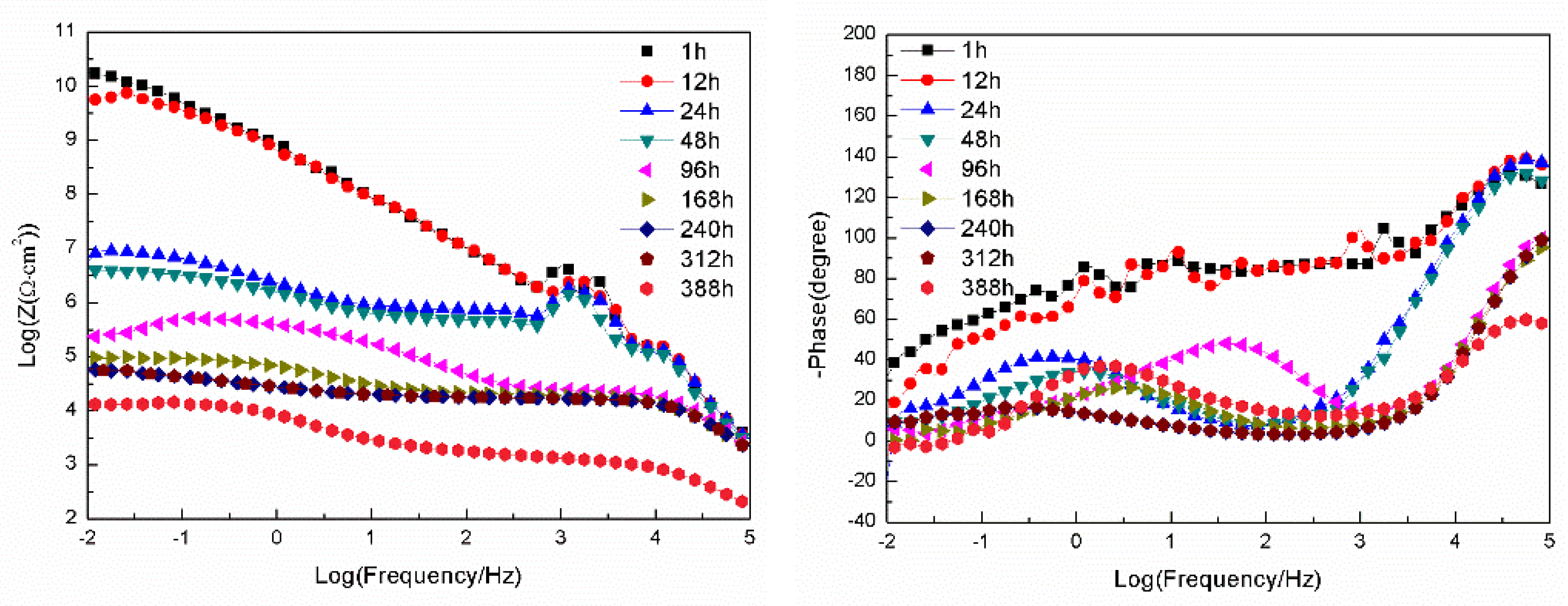
Figure 9.
Bode plots of EIS for the sample with epoxy coating on 7N01 substrate pretreated by 5 % BTESPT doped with 5×10⁻³ M cerium nitrate and 0.5 g/l zeolite particles in 3.5 wt.% NaCl solution.
Figure 9.
Bode plots of EIS for the sample with epoxy coating on 7N01 substrate pretreated by 5 % BTESPT doped with 5×10⁻³ M cerium nitrate and 0.5 g/l zeolite particles in 3.5 wt.% NaCl solution.
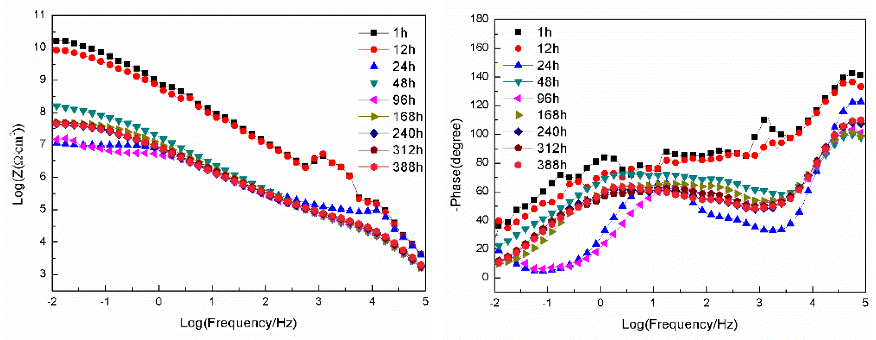
Figure 10.
Cross-sectional morphologies for the sample with epoxy coating on 7N01 substrate after 30 days salt spray test, a)low and b) high magnifications, c)EDS spectrum and mapping of d) Al and e) O in the marked area.
Figure 10.
Cross-sectional morphologies for the sample with epoxy coating on 7N01 substrate after 30 days salt spray test, a)low and b) high magnifications, c)EDS spectrum and mapping of d) Al and e) O in the marked area.
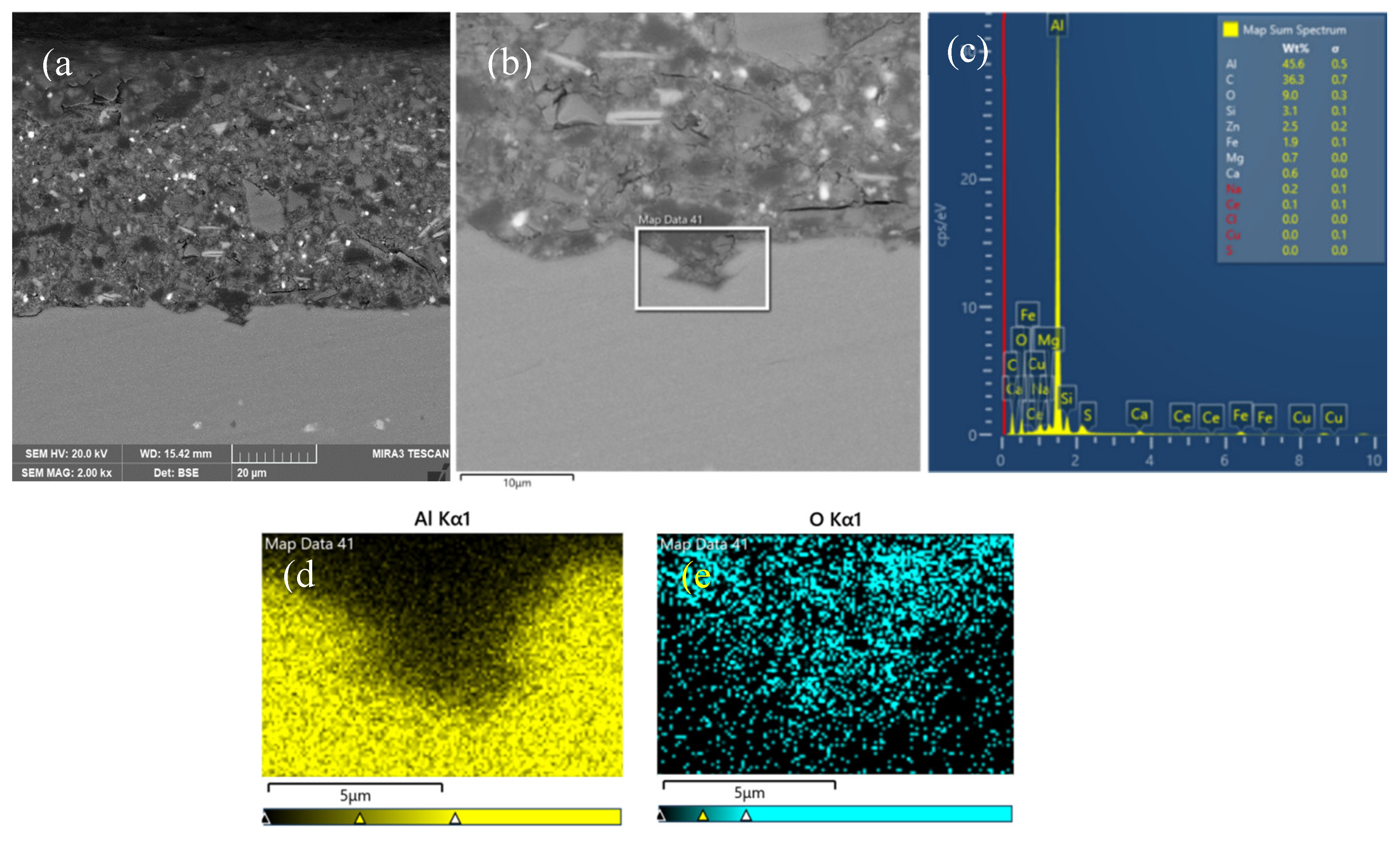
Figure 11.
Cross-sectional morphologies for the sample with epoxy coating on 7N01 substrate after 60 days salt spray test, a)low and b) high magnifications, c)EDS spectrum and mapping of d) Al and e) O in the marked area.
Figure 11.
Cross-sectional morphologies for the sample with epoxy coating on 7N01 substrate after 60 days salt spray test, a)low and b) high magnifications, c)EDS spectrum and mapping of d) Al and e) O in the marked area.
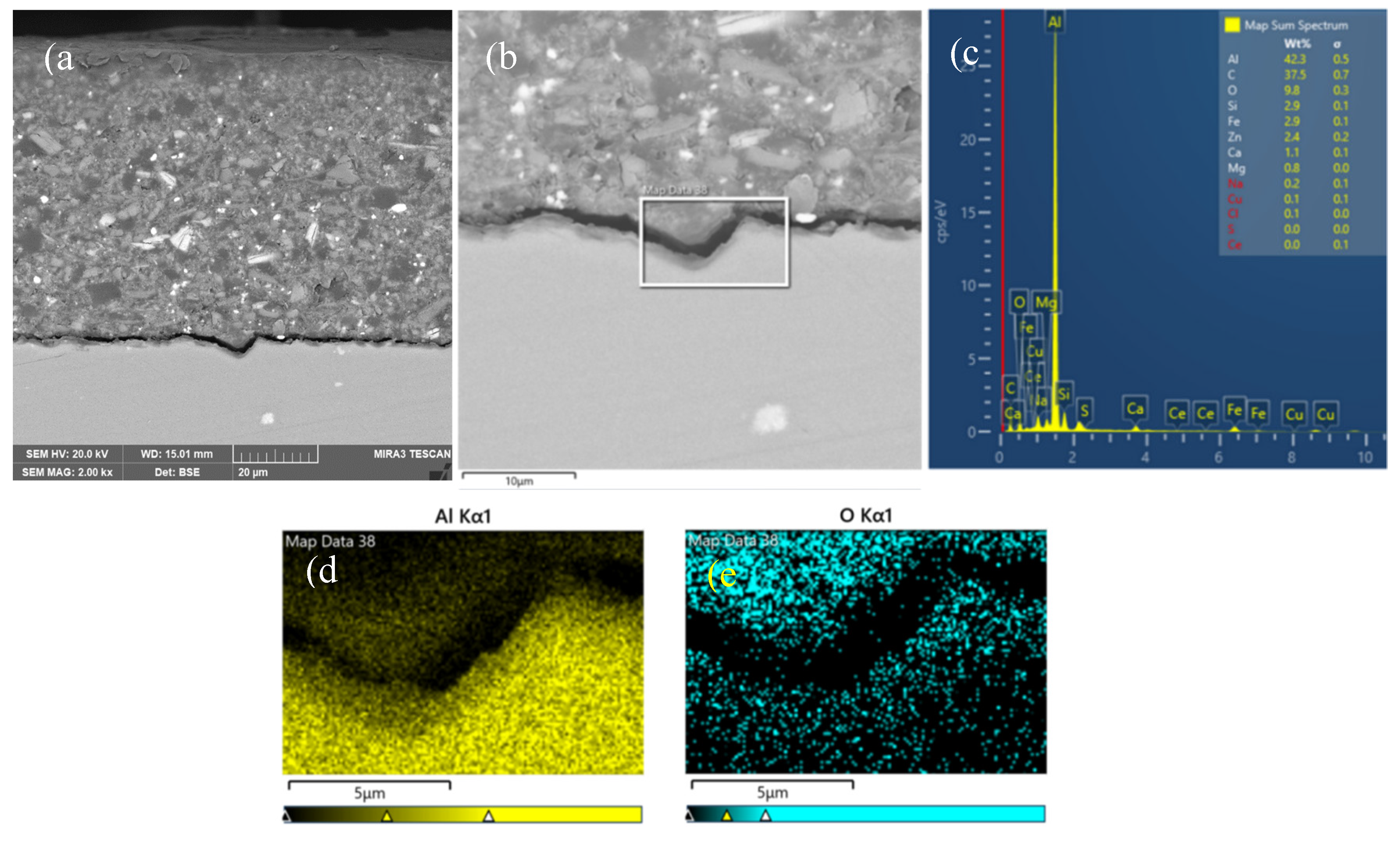
Figure 12.
Cross-sectional morphologies for the sample with epoxy coating on 7N01 substrate pretreated by the silane film doped with 5×10⁻³ M cerium nitrate and 0.5 g/l zeolite particles after 30 days salt spray test, a)low and b) high magnifications.
Figure 12.
Cross-sectional morphologies for the sample with epoxy coating on 7N01 substrate pretreated by the silane film doped with 5×10⁻³ M cerium nitrate and 0.5 g/l zeolite particles after 30 days salt spray test, a)low and b) high magnifications.
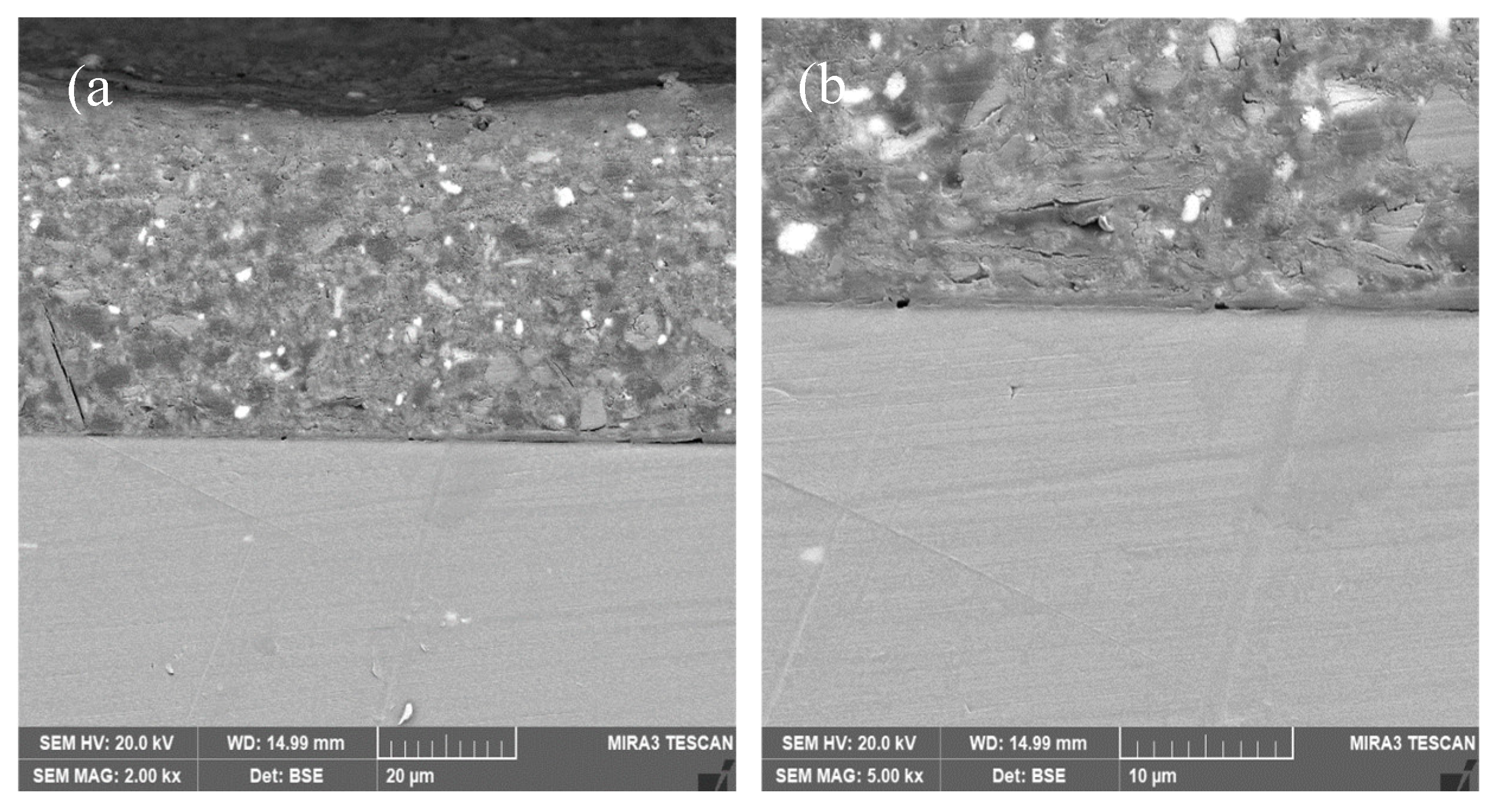
Figure 13.
Cross-sectional morphologies for the sample with epoxy coating on 7N01 substrate pretreated by the silane film doped with 5×10⁻³ M cerium nitrate and 0.5 g/l zeolite particles after 60 days salt spray test, a)low and b) high magnifications, c)EDS spectrum and mapping of d) Al, e) O, f) Si, g) S and h) Ce in the marked area.
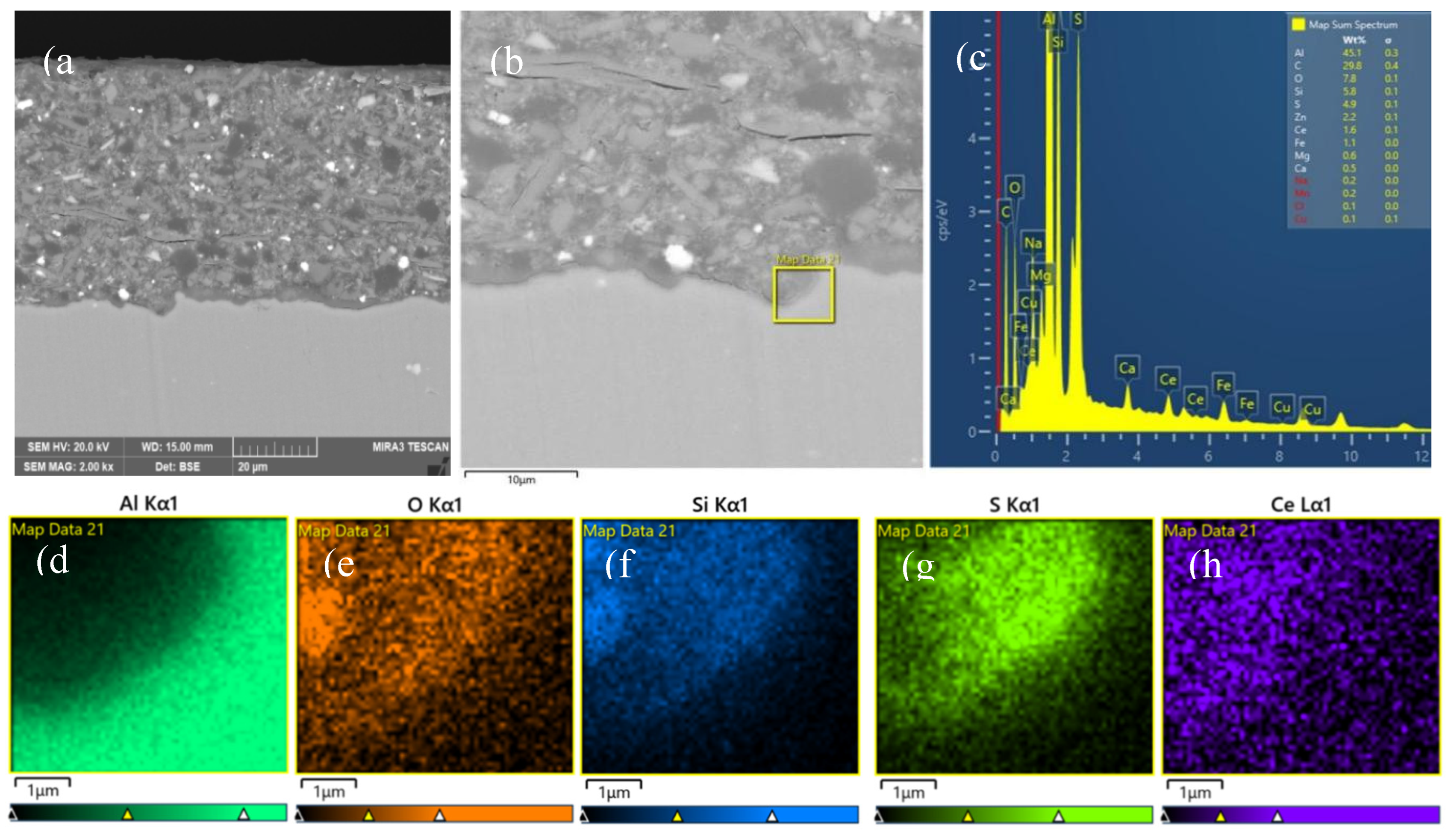

Table 1.
The chemical composition (wt.%) of the marked points in Figure 1.
Table 1.
The chemical composition (wt.%) of the marked points in Figure 1.
| point | C | O | Al | Si | S | Ce | Zn | Mg | Cu | Mn | Zr |
| 29 | 17.56 | 37.33 | 5.87 | 2.69 | 5.83 | 28.79 | 1.04 | 0 | 0.15 | 0 | 0 |
| 36 | 33.31 | 26.81 | 4.06 | 21.08 | 8.79 | 5.12 | 0.43 | 0.08 | 0.01 | 0.11 | 0 |
| 3 | 30.53 | 34.73 | 0.47 | 26.55 | 6.41 | 0.51 | 0.31 | 0.01 | 0.02 | 0 | 0.10 |
| 24 | 19.38 | 38.76 | 4.26 | 27.32 | 7.44 | 0.59 | 0.13 | 0.12 | 0.07 | 0 | 0.08 |
Table 2.
The fitted results of the polarization curves in Figure 6.
Table 2.
The fitted results of the polarization curves in Figure 6.
| Immersion time (h) | Ecorr(V/SCE) | Icorr (A/cm2) | Pitting potential(V) |
| 1 | -0.75 | 1.20×10⁻¹² | None |
| 168 | -1.15 | 2.83×10⁻⁹ | -0.80 |
| 192 | -1.09 | 1.12×10⁻⁸ | -0.87 |
| 240 | -1.04 | 5.58×10⁻⁹ | -0.87 |
| 288 | -1.10 | 1.43×10⁻⁸ | -0.88 |
Table 3.
The fitted results of the polarization curves in Figure 7.
Table 3.
The fitted results of the polarization curves in Figure 7.
| Immersion time (h) | Ecorr(V/SCE) | Icorr (A/cm2) | Pitting potential(V) |
| 1 | -0.67 | 7.02×10⁻¹³ | None |
| 168 | -0.76 | 2.78×10⁻¹² | None |
| 192 | -0.73 | 3.34×10⁻¹² | None |
| 240 | -0.70 | 4.18×10⁻¹² | None |
| 288 | -0.75 | 3.60×10⁻¹² | None |
Disclaimer/Publisher’s Note: The statements, opinions and data contained in all publications are solely those of the individual author(s) and contributor(s) and not of MDPI and/or the editor(s). MDPI and/or the editor(s) disclaim responsibility for any injury to people or property resulting from any ideas, methods, instructions or products referred to in the content. |
© 2025 by the authors. Licensee MDPI, Basel, Switzerland. This article is an open access article distributed under the terms and conditions of the Creative Commons Attribution (CC BY) license (http://creativecommons.org/licenses/by/4.0/).
Copyright: This open access article is published under a Creative Commons CC BY 4.0 license, which permit the free download, distribution, and reuse, provided that the author and preprint are cited in any reuse.


