
Submitted:
24 December 2024
Posted:
25 December 2024
You are already at the latest version
Abstract
The goal of this study was to investigate the surface morphology changes induced by cavitation erosion of a coating based on cordierite with epoxy matrix for aluminium substrate. The literature review shows a certain gap in knowledge regarding coating's resistance to wearing induced by water flow, which is a highly important property of the material immersed in or in contact with water streams. The main idea behind the investigation is that such protective coating will also improve the cavitation erosion resistance of metal substrates. The protective coatings were based on cordierite filler (88 wt.%) and epoxy resin (7 wt.%). The filler made of mixture of kaolin, alumina, and talc is obtained by a sintering procedure that took place at 1350°C. X-ray diffraction analysis and scanning electron microscopy were employed in the characterization of the produced filler. Adherence of the obtained epoxy-based protective coating and resistance to water flow were tested by the ultrasonic vibration method (i.e., cavitation erosion testing). Scanning electron microscopy was used for analysis of the coating's morphology upon cavitation erosion. Based on the value of the cavitation erosion rate and the analyzed final surface damage, it was assessed that the investigated protective coating is resistant to cavitation erosion.
Keywords:
cordierite filler
; metal substrate
; cavitation resistance
; microstructure
1. Introduction
The resistance of the substrate to various types of erosion (e.g., carbonation, chloride ion erosion, cavitation erosion via water) can be significantly increased by applying the epoxy-matrix-based coatings to metal and non-metal surfaces [1,2,3]. Numerous investigations have shown that the high density and stable chemical composition of inorganic film-forming coatings are the most important factors for creating a protective layer on the surface of the material. This layer prevents corrosive media from the environment (water, moisture, CO2, Cl-), from being in direct contact with metal elements or concrete in a structure [4,5,6,7,8,9,10]. In order to guarantee the long-term service performance of either industrial or residential metal and/or composite structures, the protective coatings have grown in importance as an adjunct technology [11,12,13]. Even though traditional coatings perform exceptionally well in terms of protection, the majority of them are produced with organic solvents and contain a number of hazardous volatile organic compounds (xylene and toluene), which does not only harm the environment but also put human health at grave risk [12]. The fundamental objective is to create a protective coating with a low organic content and a high percentage of inorganic filler with a high hardness value and adequate grain size and grain shape distribution to achieve good adherence to metal substrate in a thin layer. The obtained coating has to be non-toxic, highly erosion resistant, and easy to clean. According to the research provided by other authors [14,15], currently, the majority of applications for these coatings are found in the metal structural components of buildings, equipment parts that come into direct contact with water, cars, boats, etc.
The performance of predominantly inorganic coatings has increased over time, and their potential for use in engineering practice has grown, owing primarily to the development of micron- and sub-micron-sized materials. Specifically, materials (fillers for coatings) with different grain size- and grain shape- distributions, including very small particles (micron or sub-micron grains), show advantages in terms of adherence to the substate and evenness of the protective layer. Research has so far showed that adding raw materials such as graphene oxide, nano-silica, nano-Fe2O3, nano-TiO2, and nano-clay may effectively raise the coating density, eliminate microscopic flaws in the coating, improve the coating's mechanical characteristics, and wear resistance [16,17,18,19]. All of these factors strengthen the metal substrate's anti-erosion properties. Cordierite (2MgO·2Al2O3·5SiO2), as filler, offers various advantages regarding its properties needed for a protective coating component. This filler has low coefficient of thermal expansion, good resistance to thermal shock, good physico-mechanical properties such as hardness, flexural and compressive strength, high refractoriness, inertness towards liquid metal, and good corrosion resistance [20]. For instance, the remarkable resistance of cordierite to heat shock is a result of its extremely low coefficient of thermal expansion. Cordierite crystallizes at approximately 830°C in an orthorhombic, pseudohexagonal system to μ-cordierite, and has a comparatively low melting point of 1470°C [21]. Cordierite crystallization causes a shrinkage of about 4.7% [21]. The thermal expansion coefficient of cordierite coatings is 3.21*10−6 K−1 within the 25–400 °C temperature range [21]. Also, in the study conducted by C. Semmler et al. [21] only cordierite coatings could be applied without cracks. Cordierite coatings achieved the lowest thermal conductivity in the 50–200°C temperature range, with values less than 1.2 W/mK [21]. The goal of this work is to employ the micron and sub-micron sized synthetized inorganic filler of high hardness in non-toxic protective coating which can be used as erosion “shield” on metal surfaces. Therefore, raw mineral material – alumina, talc, and kaolin were used in the synthesis of filler which includes certain percentage of cordierite mineral phase.
A particular kind of wear known as cavitation involves the emergence, development, and implosion of vapor in a water flow. Microjets, a cavitation vortex, and intense shock waves induce high temperatures and pressure which can severely damage the substate material [22,23]. The layers on the material's surface gradually harden as a result of the energy build up. Thereby, the material progressively loses its ability to deform further, becomes more brittle, and develops fractures that deepen over time as a result of particles being removed from the fracture surface and the crack's margins, and the risk of smaller or bigger pits (holes) [24,25]. If surface damage expands, indicating cavitation-related degradation, the material may be destroyed. As a result, determining and assessing filler grain sizes and grain shapes in order to optimize them can be critical for producing protective coatings with a low risk of cavitation erosion.
The laboratory-scale synthesis of cordierite filler-based alumina, kaolin, and talc was performed in order to produce as much cordierite phase in coating as possible. Thus, obtained properly dispersed micron and sub-micron particles immersed in an epoxy matrix would provide a non-toxic protective covering that might be used as an erosion "shield" for metal (aluminum) substates. The next step was to systematically investigate the surface morphological changes generated by cavitation erosion on the resulting coating affixed to an aluminum plate. Aluminum substate was proven as non-resistant to low resistant to cavitation erosion [26]. The literature review reveals a significant level of information gap about coatings' resistance to wear caused by water flow, which is an important property of any material submerged in or in contact with water streams. The primary premise of the study is that providing a protective coating can considerably improve metal substrates resistance to cavitation erosion.
2. Materials and Methods
2.1. Raw Materials and Synthesis of the Cordierite Filler
The filler for the protective coating was made experimentally using the following basic raw materials: kaolin (distributor: Jugo Kaolin D.o.o.), aluminium (III) oxide/alumina (distributor: "Alumina" d.o.o. Zvornik), and talc (distributor: Credicom International, Beograd).
The chemical composition of the raw materials was determined by means of atomic absorption spectrometry on a Perkin Elmer Analyst 300 Instrument. The wavelength range of the device is 185-900 nm. AAS instrument has optical dual beam, monochromator with 1800 lines/mm, photo multiplicator detector and a carrier with 6 lamps with automatic positioning. Loss on ignition, measured upon firing at 1000°C, for commercial kaolin, alumina, and talc were 7.95 %, 3.17 %, and 6.91 %, respectively.
The chemical compositions of the raw components were as follows:
- (1)
- Kaolin - SiO2 =53.87 %, Al2O3 = 28.24%, Fe2O3 = 1.48%, CaO = 0.64 %, Na2O = 0.03 %, and K2O = 0.05 %;
- (2)
- Alumina - SiO2 = 0.15 %, Al2O3 = 95.12 %, MgO = 0.01 %, Fe2O3 = 0.1%, CaO = 0.17 %, Na2O = 0.04 %, and K2O = 0.02 %;
- (3)
- Talc - SiO2 = 60.97 %, Al2O3 = 1.68 %, MgO = 28.91 %, Fe2O3 = 2.23 %, CaO = 2.95 %, Na2O = 0.87 %, and K2O = 0.91 %.
The filler mix design included 29 wt.% kaolin, 35 wt.% alumina, and 36 wt.% talc. The raw materials were mixed in the given ratio in an ultra-centrifugal mill (Retsch ZM-1) for 60 minutes. Subsequently, the homogenized mixture was shaped into tablets using a conventional laboratory hydraulic press (the applied load on the machine was 1 MPa). Sintering was conducted in a Carbolite laboratory chamber furnace. The heating temperature increased from ambiental 20° to 1350°C. An oxidizing atmosphere was used. The following heating regime was used: a continuous heating rate of 10°C/min up to 1000°C, followed by a constant heating rate of 5°C/min between 1000°C and 1350°C. A three-hour delay was used at the maximum temperature. The synthetized tablets were crushed upon cooling down and subsequently ground in ultra-centrifugal mill for additional 60 minutes.
2.2. Instrumental Methods for Characterization of the Synthetized Cordierite Filler
In order to determine mineral phase composition of the synthesized filler, X-ray diffraction (XRD) technique was applied on crushed and subsequently pulverized sintered tablets. A Philips X-ray diffractometer, model PW-1710, equipped with a scintillation counter and a curved graphite monochromator was used. The intensities of the diffracted CuKα X-ray radiation (λ=1.54178Å) were measured at room temperature in intervals of 0.02° 2θ and 1 s in the range from 4 to 65° 2θ. The X-ray tube was loaded with a voltage of 40 kV and a current of 30 mA, while the slits for directing the primary and diffracted beams were 1° and 0.1 mm.
Microstructural analysis was conducted via a scanning electron microscope (SEM) - JEOL JSM-6610LV on the pulverized sintered samples. The powdery samples were coated with carbon using table-top sputter coater LEICA SCD005. The magnification of the instrument is 5 to 300,000 times. The electron source is W wire, LaB 6. The voltage is 0.3–30 kV. The instrument works with a vacuum system.
Qualitative mineralogical analysis of the samples were performed under a polarized transmitted light microscope of the brand Jenapol, Carl Zeiss-Jena. The imersion method (xylene immersion) was used for the qualitative identification of the minerals present. The magnification of the objective is 10 to 50x. Measurement of grain size and abundance factor was done on 3500-4000 grains. The analysis of grain shape and size was done using the OZARIA 2.5 software package (interval from 0 to 1), where the shape factor is determined as follows: for 0 – the cross section corresponds to the shape of a needle, for 1 – the cross section corresponds to a circle, while the grain size is given in micrometers (µm). The division according to the grain shape factor is: from 0,0-0,2 – angular; from 0,2-0,4 – subglobose; from 0,4-0,6 – subrounded; from 0,6-0,8 rounded and from 0,8-1,0 – well-rounded grain shape. The photomicrography system Studio PCTV (Pinnacle Systems) was used for recording [27].
2.3. Preparation and Mix-Design of the Protective Coating
The established mix-design of the experimental protective coating was: synthesized filler (88 wt.%), epoxy resin used as coupling agent (7 wt.%), and CoatOSil™ MP 200 (Manufacturer: Grolman Group, Neuss, Germany) used as additive (1.2 wt.%). An epoxy functional silane oligomer called CoatOSilTM MP 200 is useful in urethane, epoxy, acrylic, and polysulfide-based coatings as a crosslinker and adhesion booster. It works well with solvent-borne and water-based coatings, where it can aid in strengthening the crosslinking density to enhance adhesion to the substrate, hardness, and chemical resistance. Water (3.8 wt.%) was used as a solvent. Water causes the epoxy to plasticize, a physically based and reversible breakdown process that increases the mobility of macromolecular chains. Components were gradually added with continual mixing in a laboratory mixer. The acquired viscosity of the coating was 1200 cPs. Viscosity was determined by a laboratory viscometer, where a spindle is rotated in the epoxy fluid, according to Standard ASTM D-2393. The fluid's resistance to flow is accurately measured in centipoise (cPs).
2.4. Instrumental Methods for Characterization of the Protective Coating
The standard test method for cavitation erosion according to ASTM G32-16 [30] was employed on the experimentally prepared protective coating. Since the tested material is brittle, the ultrasonic vibratory cavitation method with a stationary sample was used [31].
The sample holder was fixed to the bottom of the water bath. The mechanical vibratory concentrator was immersed in water bath. The water temperature was maintained constant at 25±1°C. A 0.5 mm gap separated the sample from the front surface of the vibratory concentrator. Mechanical vibrations at a frequency of 20 ± 0.2 kHz were used. The amplitude of mechanical vibrations at the top of the concentrator was 50 ± 2 μm. The gap between test sample and concentrator was 0.5 mm. Under the front surface of the concentrator and the stationary-tested sample, a substantial cavitation zone was formed. The water bath was cooling the sample to keep it at a constant temperature. A pressure field was created by a continuous water flow, which induced the implosion of the cavitation bubbles on the surface of the sample. The water flow rate was 5-10 ml/s, and the temperature in the bathroom is 25±1°C. The cavitation periods employed were: 0, 15, 30, 45, and 60 minutes. Upon each testing of the samples were dried and the mass loss was measured with an analytic accuracy of ±0.1 mg. The test output represents an average of minimum three testing per sample. The cavitation damage results are presented as the mass loss diagram by charting the mass loss values on the ordinate and the time of material exposure on the abscissa. Rate of cavitation erosion was obtained using the least squares method (the tangent of the slope depicts the loss of mass during the period of cavitation activity). The measurements are conducted in accordance with ASTM G32-16. For each set of tested samples, three samples were used, and the findings represent the mean value of these measurements for each test interval.
The morphology of the samples' damaged surfaces was examined using a scanning electron microscope (JEOL JSM-6610LV) (method and instrument specified in the preceding sub-section).
3. Results and Discussion
3.1. Properties of the Synthetized Cordierite Filler
The major oxides identified in the synthesized filler are as follows: SiO2 =39.91%; Al2O3 = 44.05 %; MgO = 11.35 %; Fe2O3 = 1.55 %; and CaO = 1.6 %. LoI measured at 1000°C is 0.63 %. Obtained chemical composition varies from ‘theoretical’ chemical composition of cordierite [32,33,34]: SiO2 ≈ 48 %; Al2O3 ≈ 33 %; MgO ≈ 12 %; Fe2O3 ≈ 2.4 %. The conducted synthesis resulted in cordierite and different mineral phases such as: corundum, quartz, spinel, periclase, which can be seen fromthe X-ray diffractogram, Figure 1.
It can be seen from the diffractogram that the most intense peak of cordierite is at 10°. According to (JCPDS 13-294 (International center for diffraction data (https://www.icdd.com/).)) it can be seen that there are peaks at18°, 19°, 21,5°; 26°, 28°, 29° ect., with the peaks between 25 and 30° being only slightly less intense than the peak at 10°. Quartz (JCPDS 46–1045) reflections were present at ~26°, where the most intense peak is for quartz. The most intense peak for spinel is at ~37°, and smaller peaks are at 19°, 32°, 45°, 70°, 77°, 84° (JCPDS 77–1193). Corundum (JCPDS 46-1212) reflections are observed at 35°, 37°, 44°, 65° and 77°. Peaks for periclase are present at 44°, 61°, 80° (JCPDS 82–0512). Mohs hardness of the observed mineral phases is as follows: cordierite (7-7.5), corundum (9), spinel (10), quartz (7), and periclase (6.5). The obtained mineral phase blend indicates crystalline material with high hardness which a physical property important for a filler used in protective coating.
A SEM microphotograph of synthetized filler is given in Figure 2. From the microphotograph it can be seen that big hexagonal angular grains are present in the observed grain mixture. These particles might correspond to the cordierite mineral phase, since cordierite is characterized by the orthorhombic pseudohexagonal symmetry which gives way to a hexagonal symmetry at temperatures near the melting point [35]. Also, the cordierite particles are predominantly sizing from 10 µm to 20 µm which is in the same dimensional-range as the biggest particles in the observed mixture. Quartz grains are usually classified as very angular [36]. Their diameter is usually around 15 µm [36]. Extremely angular particles of the previously stated average diameter are visible in the observed grain-mixture. Corundum has cubic crystal morphology [37]. The size of corundum particles is below 10 µm. Small cubically-shaped grains are present in the filler mixture. Spinel mineral is characterized by sharp octahedral crystals [38]. Small needle-like or sharp octahedral particles are present in the observed grain mixture (periclase).
The measurement of grain size and shape factor was performed on 3610 grains. The average grain size is 17.16 µm. The smallest and largest measured grain sizes are 1.04 and 57.16 µm, respectively. The standard deviation is σ = 10.46. The average grain shapre factor is 0.67. Based on this data, the grains of this sample belong to the category of rounded grains. The maximum grain shape factor is 0.81 and the minimum grain shape factor is 0.15. The standard deviation is σ = 0.09. Figure 3 and Figure 4 show histograms of grain size and shape factor od cordierite samples.
The prevailing grain shape factors (numeric values are adopted from the literature [27,39,40] are in the range of 0.6 for roundness and 0.8 for sphericity (Grain shapes: http://grippo.pazsaz.com/hg252lab2.html, accessed on 15 May 2024). This means that the analyzed grains are not perfectly round or spherical (e.g. a perfect sphere has a shape factor that is equal to 1). The average grain is pseudo-round but with slightly sharp edges (grains sizing from 20 µm to 30 µm in the SEM microphotograph). Smaller grains (20–10 µm) are predominantly elongated, angular, and thin (grain shape factor 0.3 for both roundness and sphericity). Grains bigger than 30 µm have a 0.8 factor for roundness and sphericity. Namely, it can be said that average grain in the observed mixture is sub-angular to sub-rounded, which makes this inorganic filler suitable for homogenous coating suspensions. The diversity in particle size is useful because the particles with varying granulations help to create a uniform, continuous coating layer when applied to a solid surface.
3.2. Properties of Protective Coating: Superficial Damage Formation and Development
During the preparation and application of the coating on the metal substrate, no delamination was observed. When applied to an aluminum surface, the coating adheres readily and covers the surface well. The fluid does not leak or form lumps, bubbles, or drops due to uncontrolled flow. The coating dries easily in the air, does not break the dry layers, and does not rub.
Changes in the surface of the coated sample (Figure 5) were explored during the analysis of resistance to cavitation using the ultrasonic vibration method. The mechanism of damage caused by cavitation was determined. Figure 5 shows pictures of coated metal surfaces. Figures 5a–e demonstrate the evolution of the cavitation effect on the protective coating. Figure 5a illustrates the starting sample prior to cavitation erosion. The period of no mass loss, known as the incubation period, is brief, lasting approximately 2 minutes. After 15 minutes (Figure 5b), mild damage occurs at the peripheral edges of the sample. A small number of shallow pits are emerging. After 30 minutes of cavitation erosion (Figure 5c), the additional pits emerge around the peripheral part of the sample exposed to the water stream. After 45 minutes (Figure 5d), the number of cavitation pits significantly increased, especially in the central part of the exposed coating (i.e., coated metal substrate). 60 minutes of cavitation (Figure 5e) did not destroy or extremely deteriorate the coating; it produce a small number of deep pits. No cracks or delamination of the coating from the metal substrate are observed.
The formation of superficial pits, i.e., damage that occurs to the surface of the coating, is a result of the slow loss of mass from the coating’s surface. The mass loss depicts the damage outcomes after each cavitation sequence (i.e., 0, 15, 30, 45, and 60 min). After 15 minutes of erosion, the sample lost 3 mg, which is approximately 0.9 % of the total sample weight. 30 and 45 minutes of erosion caused 1.4 % and 2.3 % of mass loss, respectively. The highest mass loss (3.6 %) was registered after 60 minutes of cavitation erosion. The rate of cavitation is calculated from the measured mass loss for every testing period. The points of the diagram are approximated by a straight line using the least squares method. The tangent of the slope depicts the loss of mass during the period of cavitation activity and represents the rate of cavitation erosion. For each set of tested samples, three samples were used, and the findings represent the mean value of these measurements for each test interval. The cavitation rate given in Figure 6 is a quantifiable measurement of the intensity of material degradation caused by cavitation.
The calculated cavitation rate for the synthetized coating based on cordierite is 0.16 mg/min (as seen from the diagram provided in Figure 6). According to the photographs of the coated metal plates (Figue 5) and the mass loss measured during testing, it can be established that small pits arise in the early stages of the cavitation process, and their proportions fluctuate as the process progresses. The mass loss reflects and follows the pit creation process. It is observed that the cavitation erosion of the examined protective coating is a slow-paced process that shows the absence of cracks and no greater loss of coating mass. It can be assumed that there is also no loss of the coating's protective characteristics since the cavitation erosion runs slowly.
Cavitation erosion is a surface deterioration phenomenon that can cause significant damage to hydraulic devices and structural elements. As previously stated in the Introduction chapter, refractory coatings applied to the surfaces of hydraulic system equipment parts or underwater construction elements help to improve the base material's resistance to wear and damage caused by cavitation. To acquire fire-resistant coatings with pre-designed properties, extra attention should be devoted to component selection from the coating composition, as well as study into coating production techniques. Grinding and mechanical activation processes are used to produce refractory fillers with certain grain sizes and shapes. For the synthesis of coatings with high rheological properties for the protection of metal and non-metal surfaces and application in harsh exploitation conditions (effect of wear, corrosion, and cavitation), to which parts of equipment in the process industry are exposed, the choice of binders, organic solvents, and additives to maintain the suspension is crucial. A high-strength, corrosion-resistant filler with high hardness and strength is chosen beforehand to guarantee the substrate's surface protection throughout time. To minimize the rate at which damage to the coated surface forms and progresses, extra care is taken in filler preparation. The test results for various materials can be compared since the ASTM G 32 standard stipulates that the tests conducted under the influence of cavitation must be conducted under identical test settings. This is crucial for the selection of materials to be used in particular exploitation conditions. The cavitation resistance of various materials can be assessed based on the value of the cavitation speed, which is defined by the ASTM G32 standard as the mass loss during the cavitation time. This is crucial for the selection of materials under particular exploitation conditions. The rate of cavitation degradation has no set limits provided in Standard. Both visual inspection and mass loss can be used to detect degradation (supported by microscopic procedures). Real-scale and laboratory-scale models differ from one another as well. In other words, the water force generated in the lab model is practically greater than the force generated on the structural element on a real-sized scale (depending on the size of the tested sample). As a result, testing has been conducted across shorter time periods (e.g., intervals from 15 to 60 minutes). Cavitation erosion would take a lot longer to develop in real scale surrounding. The next phase in our work would be to test different coatings on a pilot model at the semi-industrial level.
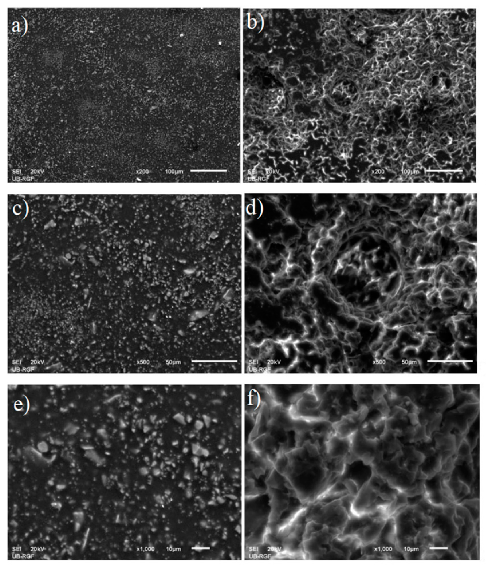
The SEM microphotographs (recorded with different optical zooms) of the protective coating prior to cavitation erosion testing (i.e., 0 minutes (a), c), and e) and after 60 minutes of exposure to water erosion (b), d), and f) are presented in Figure 7.
The original undamaged coating presented on the SEM microphotographs on the left depicts evenly distributed filler particles of different shapes and sizes immersed in the epoxy matrix. There are no damages, bubbles, or delamination of the coating applied to the metal substrate. The samples of protective coating recorded after the final cavitation erosion period of 60 minutes are given on the right. As it can be seen from the microphotographs, the pits are predominantly superficial. There are no void clusters of deeper channels starting from the superficial cavitation pits. The surfaces of the pits are smooth and seemingly shallow. Thereby, the metal substrate could not be damaged by water stream action due to the presence of the protective coating.
The coating is a continuous layer on the substrate because the filler particles and the binder (epoxy matrix) are connected. This is found prior to the onset of cavitation (i.e., this can be seen in SEM micro-photographs of the samples recorded prior to the cavitation erosion – Figure 7 a); c); e)). Both the epoxy matrix and the filler particles are being eroded together at the same time during erosion. Following a 60-minute exposure period, the protective layer's surface sustained damage (Figure 7 b); d); f)). Extensive observation revealed that whole grain tearing, devoid of coating layer plastic deformation, is the primary mechanism of damage. As a result, the preparation of refractory fillers and their pulverization through the operations of grinding and micronization to the desired sizes and shapes of powder grains received particular attention during the planning of sample preparation. Grain crushing helps down the rate of damage to the coating layers, and the applied refractory fillers are highly resilient to cavitation erosion. After 60 minutes of exposure (Figure 7 b); d); f))., the coating developed smooth, acute dimples on its surface. This suggests that the coating mass gradually decreased without plastic deformation of the material.
4. Conclusions
In this study, protective coatings based on cordierite filler (88 wt.%) and epoxy resin (7 wt.%) for metal substates (aluminum) were manufactured and tested for cavitation erosion resistance. The average grain in the filler mixture is sub-angular to sub-rounded, making it suitable for homogeneous coating solutions. The protective coating adhered properly to the aluminum plate, completely covering the surface and leaving no bumps or bubbles. The coating dries quickly in the air and exhibits no delamination. The cavitation rate of 0.16 mg/min suggests a slow deterioration of the coating. The morphology of the protective coating samples following the last cavitation erosion phase of 60 minutes revealed predominantly superficial pits. There are no empty clusters of deeper channels beginning with the surface cavitation pits. The presence of the protective layer prevented the metal substrate from being harmed by water stream action. This study shows that the proposed protective coating may be used in environments with high cavitation loads and provides protection for the substrate material which will be tested on semi-industrial scale as the next step of the study.
Author Contributions
Conceptualization, M.P., M.D., J.C., and S.D..; Methodology, M.P., M.D., S. A., N.T., and Z.Č. ; Investigation, M.P., M.D., J.N.., S.D., Z.Č., and S.A.; Writing—Review & Editing, M.P. and M.D.
Funding
This research was funded by the Ministry of Education, Science and Technological Development of the Republic of Serbia (Contracts No.: 451-03-47/2023-01/200213, 451-03-66/2024-03/200012).
Conflicts of Interest
The authors declare no conflict of interest.
References
- Almusallam, A.; Khan, F.; Dulaijan, S.; Al-Amoudi, O. Effectiveness of surface coatings in improving concrete durability. Cem. Concr. Compos. 2003, 25, 473–481. [Google Scholar] [CrossRef]
- Pan, X.; Shi, Z.; Shi, C.; Ling, T.-C.; Li, N. A review on concrete surface treatment Part I: Types and mechanisms. 2016, 132, 578–590. [CrossRef]
- Korjakins, A.; Kara, P.; Toropovs, N. Improving Quality of High Performance Concrete by Cavitation Treatment of the Raw Materials. Procedia Eng. 2013, 57, 597–604. [Google Scholar] [CrossRef]
- Lu, X.; Wang, L.; Chen, C.; Chen, J.; Zhou, J.; Deng, J. Study on the influence mechanism of material damage on the cavitation erosion properties of hydraulic concrete. Constr. Build. Mater. 2023, 400. [Google Scholar] [CrossRef]
- Park, D. Carbonation of concrete in relation to CO2 permeability and degradation of coatings. Constr. Build. Mater. 2008, 22, 2260–2268. [Google Scholar] [CrossRef]
- Aguiar, J.B.; Júnior, C. Carbonation of surface protected concrete. Constr. Build. Mater. 2013, 49, 478–483. [Google Scholar] [CrossRef]
- Shariatmadar, M.; Gholamhosseini, P.; Abdorrezaee, Z.; Ghorbanzadeh, S.; Feizollahi, S.; Hosseini, F.; Shahraki, F.A.; Mahdavian, M. Leveraging polyaniline grafted micaceous iron oxide as a dual active-barrier pigment for anti-corrosion polymer coatings. Surf. Coatings Technol. 2024, 479. [Google Scholar] [CrossRef]
- Wang, H.; Feng, P.; Lv, Y.; Geng, Z.; Liu, Q.; Liu, X. A comparative study on UV degradation of organic coatings for concrete: Structure, adhesion, and protection performance. Prog. Org. Coatings 2020, 149, 105892. [Google Scholar] [CrossRef]
- Selvaraj, R.; Selvaraj, M.; Iyer, S. Studies on the evaluation of the performance of organic coatings used for the prevention of corrosion of steel rebars in concrete structures. Prog. Org. Coatings 2009, 64, 454–459. [Google Scholar] [CrossRef]
- Qu, H.; Feng, M.; Li, M.; Tian, D.; Zhang, Y.; Chen, X.; Li, G. Enhancing the carbonation and chloride resistance of concrete by nano-modified eco-friendly water-based organic coatings. Mater. Today Commun. 2023, 37. [Google Scholar] [CrossRef]
- Pavlovic, M.; Dojcinovic, M.; Nikolic, J.; Terzic, A.; Pavicevic, V.; Drmanic, S.; Kurtanovic, E. Application of waste raw materials as a reinforcement for protective coatings based on pyrophyllite. Chem. Ind. Chem. Eng. Q. 2024, 29–29. [Google Scholar] [CrossRef]
- Gu, S.; Shi, H.; Li, J.; Xu, H.; Udoh, I.I.; Liu, F.; Han, E.-H. Self-diagnosing and active protective dual-functional water-borne polyurethane coating based on smart mesoporous containers. Prog. Org. Coatings 2023, 183. [Google Scholar] [CrossRef]
- Sun, F.-C.; Fu, J.-H.; Peng, Y.-X.; Jiao, X.-M.; Liu, H.; Du, F.-P.; Zhang, Y.-F. Dual-functional intumescent fire-retardant/self-healing water-based plywood coatings. 154, 1061; 87. [Google Scholar] [CrossRef]
- S. A. T. Nejad, S. S. A. T. Nejad, S. Amanian, E. Alibakhshi, M. Hajisoltani, S. A. Haddadi, M. Arjmand, B. Ramezanzadeh, M. Mahdavian. Enhancing epoxy-silicone coating's protection performance: Harnessing the power of sulfur-doped graphene oxide. Prog. Org. Coat. 2024. [Google Scholar] [CrossRef]
- K. Bobzin, L. K. Bobzin, L. Zhao, H. Heinemann, E. Burbaum, S. Li. Effect of heat treatment on the structure, fracture toughness and oxidation behavior of a silicon coating by atmospheric plasma spraying. Surf. Coat. Technol. 2023. [Google Scholar] [CrossRef]
- Qi, C.; Dam-Johansen, K.; Weinell, C.E.; Wu, H. Synthesis of micro-structured zinc particles by thermal evaporation and their application in zinc containing coatings for steel corrosion protection. Prog. Org. Coatings 2023, 187. [Google Scholar] [CrossRef]
- Xiao, X.; Wang, D.; Li, Y.; Jackson, E.; Fang, Y.; Zhang, Y.; Xie, N.; Shi, X. Investigation into the Synergistic Effect of Nano-sized Materials on the Anti-corrosion Properties of a Waterborne Epoxy Coating. Int. J. Electrochem. Sci. 2016, 11, 6023–6042. [Google Scholar] [CrossRef]
- Soleimani, M.; Bagheri, E.; Mosaddegh, P.; Rabiee, T.; Fakhar, A.; Sadeghi, M. Stable waterborne epoxy emulsions and the effect of silica nanoparticles on their coatings properties. Prog. Org. Coatings 2021, 156, 106250. [Google Scholar] [CrossRef]
- Yao, H.; Li, L.; Li, W.; Qi, D.; Fu, W.; Wang, N. Application of nanomaterials in waterborne coatings: A review. Resour. Chem. Mater. 2022, 1, 184–200. [Google Scholar] [CrossRef]
- Semmler, C.; Gyoktepeliler-Akin, E.; Killinger, A. Plasma sprayed ceramic coatings for the thermal protection of carbon fiber reinforced plastics (CFRP): Thermal and mechanical properties of YSZ, aluminum titanate, cordierite and mullite coatings. Surf. Coatings Technol. 2023, 462. [Google Scholar] [CrossRef]
- M. Ferraris, M. M. Ferraris, M. Salvo, F. Smeacetto. Cordierite-mullite coating for SiC/SiC composites. J. Euro. Ceram. Soc. 2002. [Google Scholar] [CrossRef]
- Wei, X. Shi, D. Cui, Z. Wei, S. Hong. Effect of 3.5 % NaCl solution with different Na2S concentrations on ultrasonic cavitation erosion behaviors of HVOF sprayed WC-Ni coatings. Ultrason. Sonochem. 2023. [Google Scholar] [CrossRef]
- Zhang, Z.; Zhao, L.; Si, C.; Tian, Y.; Xu, S. Microstructure development and cavitation erosion resistance enhancement of additive manufactured Hastelloy C276 alloy coating on martensitic stainless–steel via directed energy deposition. Opt. Laser Technol. 2023, 171. [Google Scholar] [CrossRef]
- Kumar, P.; Singal, S.; Gohil, P.P. A technical review on combined effect of cavitation and silt erosion on Francis turbine. Renew. Sustain. Energy Rev. 2023, 190. [Google Scholar] [CrossRef]
- Lu, X.; Wang, L.; Chen, C.; Chen, J.; Zhou, J.; Deng, J. Study on the influence mechanism of material damage on the cavitation erosion properties of hydraulic concrete. Constr. Build. Mater. 2023, 400. [Google Scholar] [CrossRef]
- Dojčinović, M.; Cvetković, R.P.; Sedmak, A.; Popović, O.; Cvetković, I.; Radu, D. Effect of Shielding Gas Arc Welding Process on Cavitation Resistance of Welded Joints of AlMg4.5Mn Alloy. Materials 2023, 16, 4781. [Google Scholar] [CrossRef] [PubMed]
- B. Kljajević: Software program OZARIA 2.5 for determining the size and shape of grains of refractory fillers, VAGA Lab, Belgrade, Serbia (2000).
- Pavlovic, M.; Andric, L.; Radulovic, D.; Drmanic, S.; Djordjevic, N.; Petrov, M. Influence of mechanical activation of a cordierite -based filler on sedimentation stability of lost foam refractory coatings. Sci. Sinter. 2019, 51, 15–25. [Google Scholar] [CrossRef]
- M. Pavlović, M. M. Pavlović, M. Dojčinović: Kavitaciona oštećenja refrakcionih materijala, Akademska misao, Belgrade, Serbia, 2020, p. 7466. [Google Scholar]
- ASTM G32-16 Red Standard Test Method for Cavitation Erosion Using Vibratory Apparatus (Standard + Redline PDF Bundle), https://webstore.ansi.org/standards/astm/astmg3216red (accessed 15.01. 2024.
- M. Hauer, F. M. Hauer, F. Gärtner, S. Krebs, T. Klassen, M. Watanabe, S. Kuroda, W.Kro¨mmer, K. Henkel. Process selection for the Fabrication of cavitation erosion-Resistant bronze Coating by Thermal and Kinetic Spraying in Maritime Applications. J. Therm. Spray Tech. 30 (2021) 1310. [CrossRef]
- Geiger, C.A.; Rager, H.; Czank, M. Cordierite III: the site occupation and concentration of Fe3+. Contrib. Miner. Pet. 2000, 140, 344–352. [Google Scholar] [CrossRef]
- Götze, J.; Pan, Y.; Müller, A. Mineralogy and mineral chemistry of quartz: A review. Miner. Mag. 2021, 85, 639–664. [Google Scholar] [CrossRef]
- Goudar, S. P.; Shah, S. S.; Shirali, G. S. Echocardiography of Coarctation of the Aorta, Aortic Arch Hypoplasia, and Arch Interruption: Strategies for Evaluation of the Aortic Arch. Cardiol Young 2016, 26(8), 1553–1562. [Google Scholar] [CrossRef] [PubMed]
- F.P. Glasser. Cordierite. In Concise Encyclopedia of Advanced Ceramic Materials, Editor(s): R.J. Brook, Pergamon Press, Oxford, UK, 1991, p. 9780; -92. [CrossRef]
- J. Juan, K. J. Juan, K. Zubillaga. Roundness in quartz grains from inland and coastal dune sands, Altar Desert, Sonora, Mexico. Bol. Soc. Geol. Mex. 2009. [Google Scholar] [CrossRef]
- Ma. del Carmen Gutiérrez-Castorena, W. R. Ma. del Carmen Gutiérrez-Castorena, W. R. Effland. 21 - Pedogenic and Biogenic Siliceous Features. In Interpretation of Micromorphological Features of Soils and Regoliths in Editor(s): G. Stoops, V. Marcelino, F. Mees, Elsevier, Amsterdam, Netherlands, 2010, p. 9780. [Google Scholar] [CrossRef]
- Arai, S.; Tamura, A.; Miura, M.; Morishita, T. Origin of spinel-hosted mineral inclusions in mantle peridotite from Setogawa in the Circum-Izu Massif Serpentine Belt, central Japan: Implications for the chromitite genesis. Ore Geol. Rev. 2021, 140, 104422. [Google Scholar] [CrossRef]
- Hossain, Z.; Fabricius, I.L.; Christensen, H.F. Elastic and nonelastic deformation of greensand. Lead. Edge 2009, 28, 86–88. [Google Scholar] [CrossRef]
- Santamarina, J.C. and Cho, G. Csoil. Behavior: The Role of Particle Shape. Conference on Advances in Geotechnical Engineering, London, 29-31 March 2004, 604-617.
Figure 1.
X-ray diffractogram of synthesized cordierite filler.
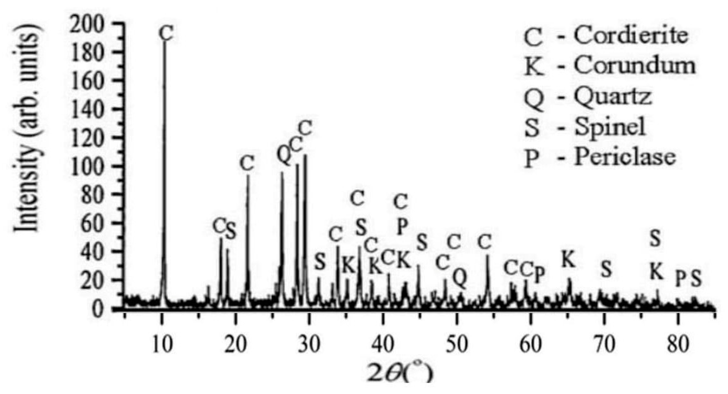
Figure 2.
SEM microphotograph of synthesized cordierite filler.
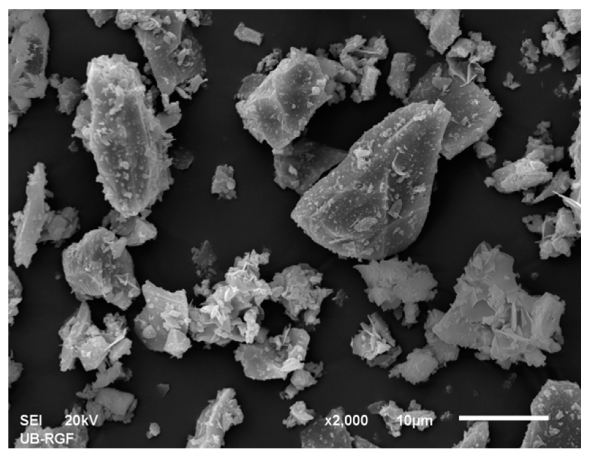
Figure 3.
Grain size distribution of the synthetized cordierite filler.
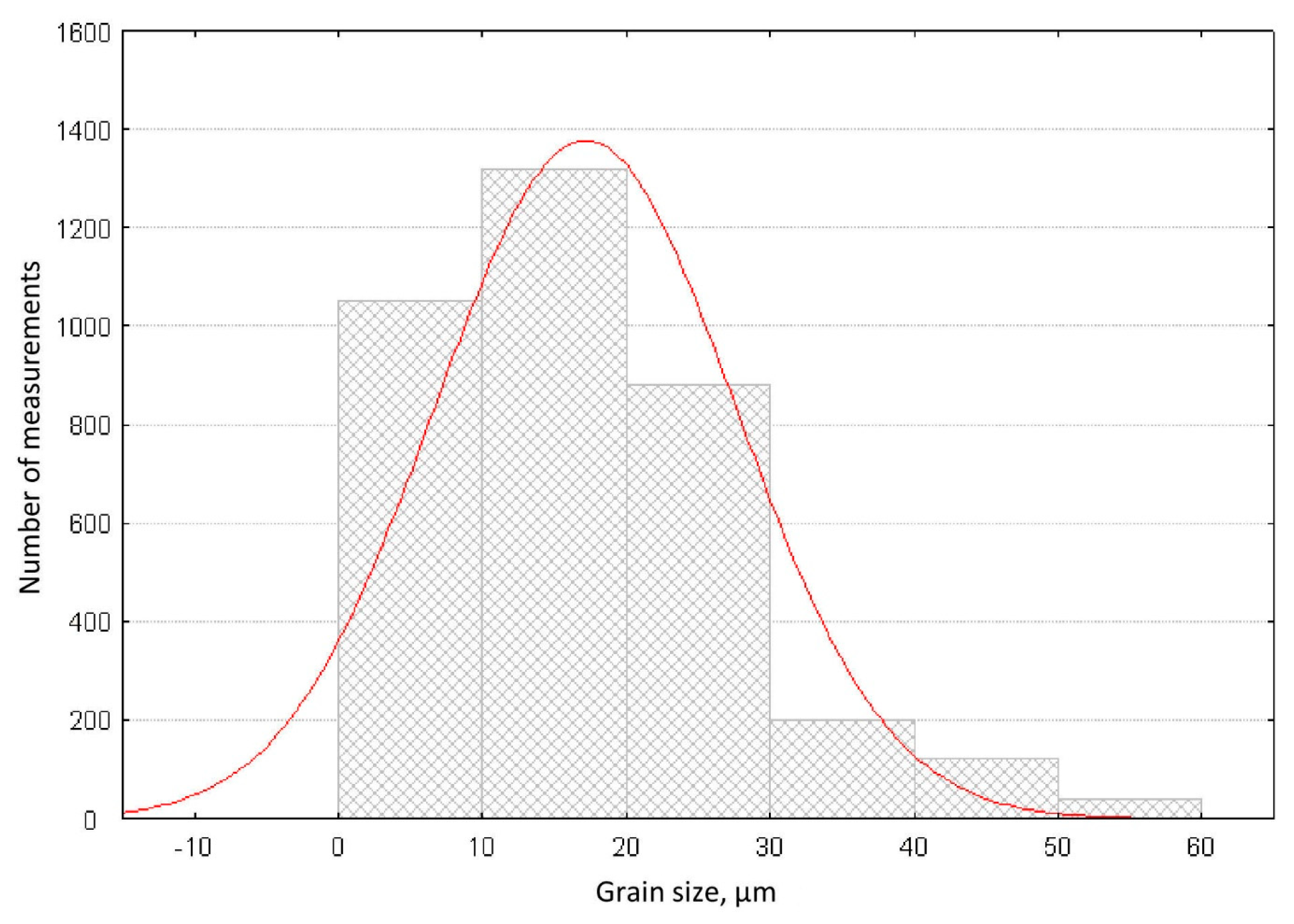
Figure 4.
Grain shape factor distribution of the synthetized cordierite filler.
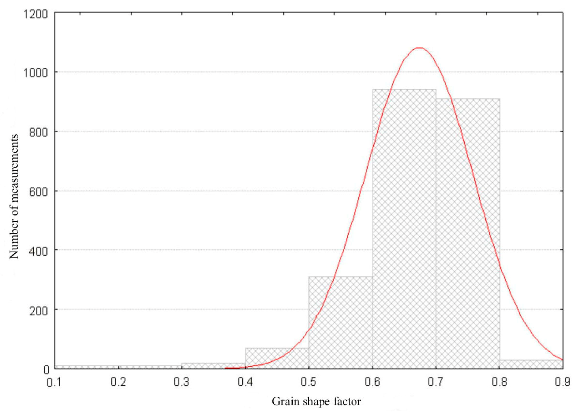
Figure 5.
Photographs of the coated surface after cavitation erosion for durations: a) 0; b) 15; c) 30; d) 45; and e) 60 minutes.
Figure 5.
Photographs of the coated surface after cavitation erosion for durations: a) 0; b) 15; c) 30; d) 45; and e) 60 minutes.
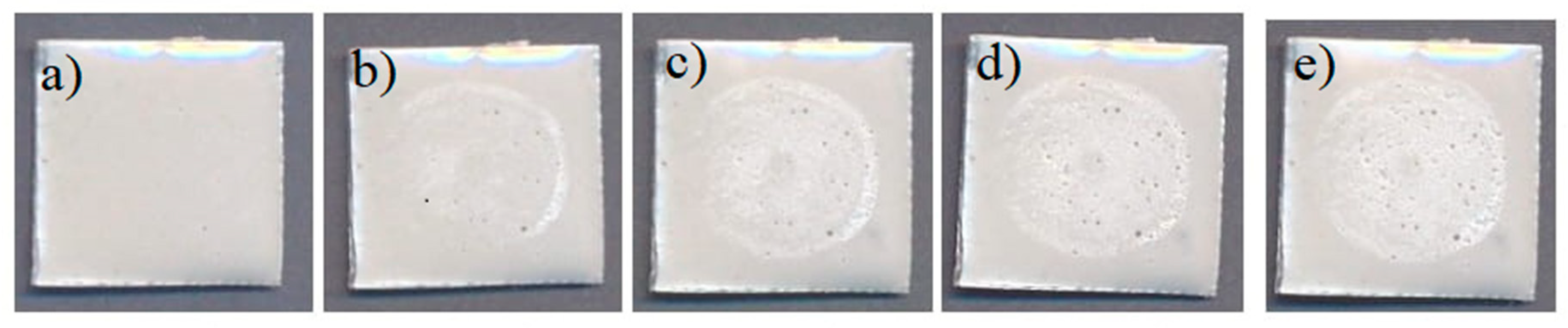
Figure 6.
Cavitation erosion rate of the protective coating based on cordierite.
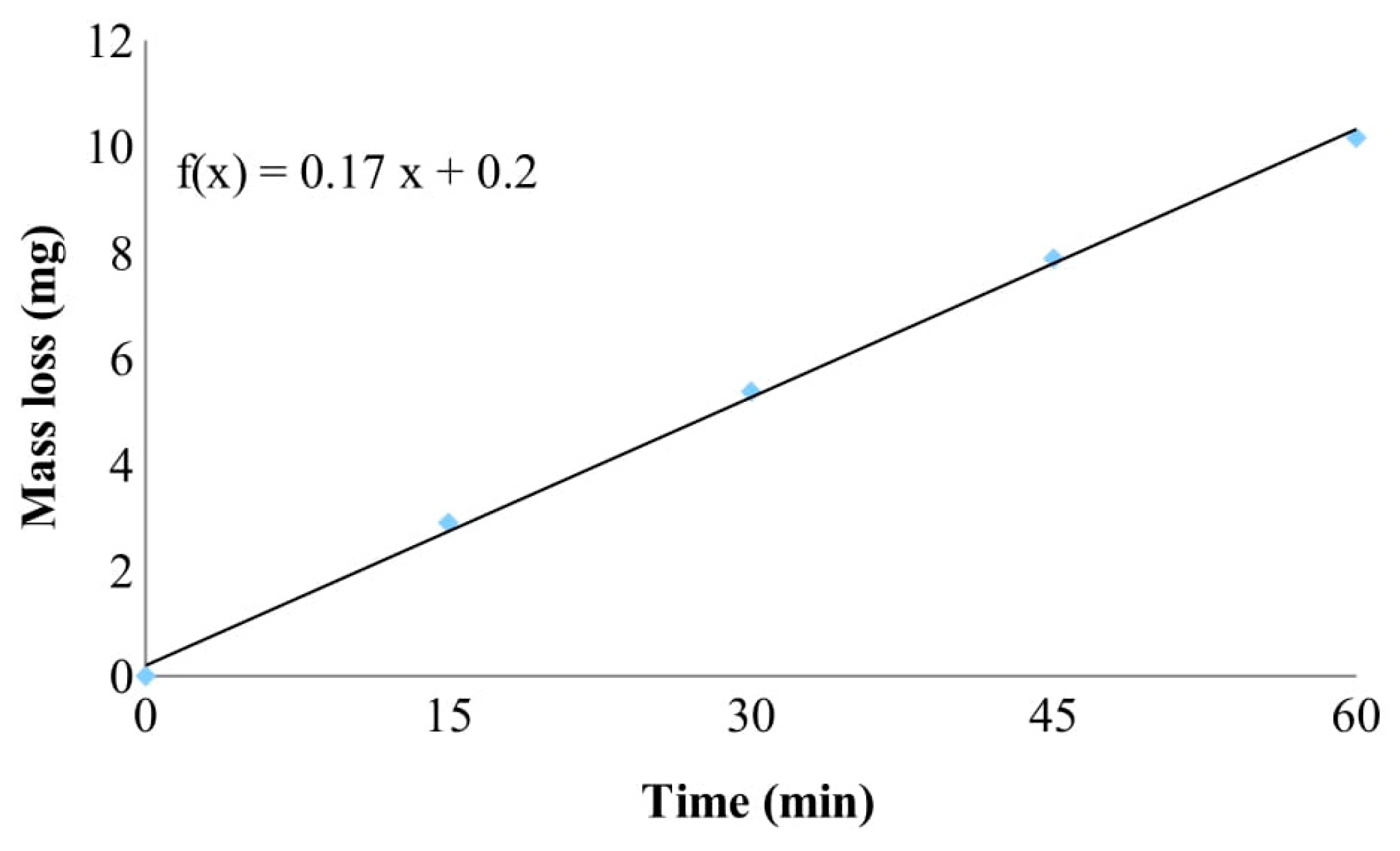
Figure 7.
SEM microphotographs of protective coating after: a); c); and e) 0 min, and b); d); and f) 60 minutes of cavitation erosion.
Figure 7.
SEM microphotographs of protective coating after: a); c); and e) 0 min, and b); d); and f) 60 minutes of cavitation erosion.
Disclaimer/Publisher’s Note: The statements, opinions and data contained in all publications are solely those of the individual author(s) and contributor(s) and not of MDPI and/or the editor(s). MDPI and/or the editor(s) disclaim responsibility for any injury to people or property resulting from any ideas, methods, instructions or products referred to in the content. |
© 2025 by the authors. Licensee MDPI, Basel, Switzerland. This article is an open access article distributed under the terms and conditions of the Creative Commons Attribution (CC BY) license (https://creativecommons.org/licenses/by/4.0/).
Copyright: This open access article is published under a Creative Commons CC BY 4.0 license, which permit the free download, distribution, and reuse, provided that the author and preprint are cited in any reuse.


