
Submitted:
23 June 2025
Posted:
25 June 2025
You are already at the latest version
Abstract
This paper explores the design space for thermal management in electric vertical take-off and landing aircraft using model-based approaches. The aim is to develop and validate a model-based design optimization method for predicting real-time battery thermal behaviour. BTMS test rig configurations are employed to investigate the design of battery sub-packs and thermal systems, integrated with thermal modeling for simulation-based analysis. Additionally, parametric design optimization utilizing Genetic Algorithm (GA) and Simultaneous Perturbation Stochastic Approximation (SPSA) methods was implemented to enhance thermal distribution while reducing structural weight. At a 30% state of charge, performance metrics improve by 3.64% when employing a detailed thermal module battery compared to a lumped module, along with a 2.67% increase from the use of an edge module. The simulation decreased the average peak temperature by up to 22% when active cooling and logical thermal variant sweep strategies were applied. Results from simulated missions demonstrate effective thermal regulation, with temperature gradients maintained within safety thresholds. This approach enables the early-stage validation of battery thermal strategies within aviation design workflows. Mission-specific optimization establishes the foundation for integrating thermal modules in next-generation electric aircraft. These insights underscore the feasibility of the research idea for engineering implementations.
Keywords:
BTMS
; electric aircraft (VTOL)
; GA
; Lithium-ion
; model-based
; SPSA
; test rig
; optimization
1. Introduction
The rapid development of electric propulsion technologies has accelerated the production of electric vertical take-off and landing (eVTOL) aircraft, particularly in urban air mobility (UAM)[1]. This rising interest in refining electric aircraft designs highlights the need for flexible and precise models of battery thermal management systems. Battery thermal management is particularly vital, focusing on preventing overheating while ensuring system efficiency [2]. This paper explores two model-based test-rig techniques for managing battery thermal systems. Optimization methods [3] are utilized on a conceptual electric aircraft model to evaluate its performance and applicability. Although considerable advancements have been made in battery cooling techniques, the current literature primarily focuses on steady-state simulations or isolated thermal models. There is a significant shortfall of integrated, system-level modeling frameworks that address both the electrical and thermal properties of Lithium-ion batteries, which are the current standard in electric aviation. These batteries exhibit temperature-sensitive behaviours that significantly influence performance, safety, and durability. Uncontrolled temperature increases can result in thermal runaway, capacity degradation, or loss of efficiency, all of which are intolerable in safety-critical aviation scenarios. To mitigate these dangers, advanced Battery Thermal Management Systems (BTMS) must be designed to maintain uniform temperatures across battery packs, support the integration of electric aircraft powertrains, and optimize thermal design despite varying mission demands. Few studies combine optimization with real-time thermal simulation, limiting the investigation of lightweight and effective thermal solutions that could enhance electric aircraft configurations[4]. This research proposes and evaluates the modeling, sizing, and optimization of electric aircraft battery packs to advance thermal management strategies, bridge the gap in co-simulation analysis, and introduce new battery thermal test-rig modeling approaches.
2. Setup and Methodology
2.1. Electric Aircraft VTOL Powertrain Modeling
Electric Vertical Take-Off and Landing (VTOL) Aircraft Power Network: This conceptual, fully electric aircraft model features eight propellers powered by motors connected to a battery through an electrical network. Figure 1 illustrates the architecture of the eight-propeller electric aircraft VTOL dynamics model, emphasizing its electrical power distribution and propulsion system design. This design facilitates energy transfer from the onboard battery system to the propulsion and avionics components.
The battery system is the primary energy source, providing high-voltage DC power (250 VDC) to every power converter. These converters manage and supply electrical energy to eight propulsion motors, each of which powers a propeller. The motors are symmetrically arranged across the aircraft’s wings to ensure balanced thrust distribution [5,6]. This module utilizes Simscape within Simulink to model vertical take-off and landing aircraft, connecting motors to a battery through an electrical network that energizes eight propellers. To determine the optimal size for the battery pack, the battery model is parameterized using Simulink for parameter sweeps. This enables engineers to select an appropriate cell, design the battery pack, and establish the thermal system based on this strategic innovation. The battery model in the primary model is created with a suitable level of detail for the engineering task at hand. Modules for testing rig harnesses are designed to explore battery subpack designs and enhance the thermal management system. The optimized electric aircraft model includes a battery, two DC networks, and a mechanical aircraft model that functions as a load on the high-voltage DC network. The low-voltage DC network consists of loads that activate and deactivate throughout the flight cycle.
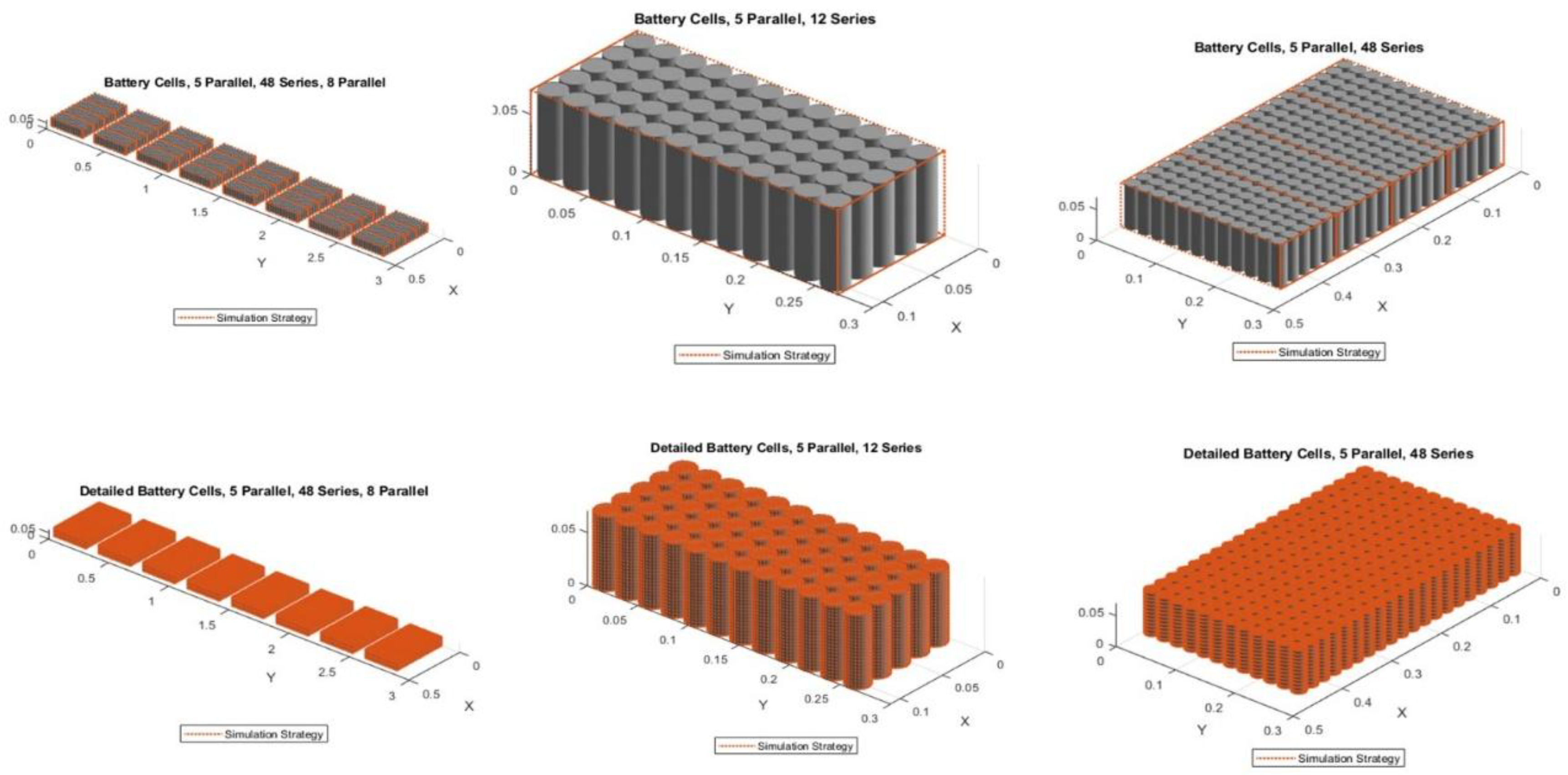
2.2. Battery Pack Configurations
Battery and Thermal Subsystems: The battery pack model is created and parameterized in MATLAB, allowing for parameter sweeps to determine the optimal size of the battery assembly modules [6]. Each subpack contains 48 cells arranged in series, with five cells in parallel for every series string. These cells are cylindrical, with specific dimensions, mass, and thermal properties. Accurate thermal settings are crucial for maintaining simulation fidelity. This setup results in 1,920 cells (5 parallel × 48 series × 8 parallel). The hierarchical formation is constructed progressively. Each cylindrical cell has a radius of 10.775 mm, a height of 70.15 mm, and a mass of 66.9 g. Thermal ports simulate behaviours that are sensitive to temperature. The series arrangement enables precise modeling at the ends, which is crucial for accurate voltage readings, while the parallel configuration groups the central cells while keeping the ends separate to enhance current distribution. This method reduces the number of elements simulated without sacrificing essential details. Utilizing the features of Simscape Battery Builder to automate the development of a sophisticated system is vital. This showcases how Simulink tools enhance battery pack design and simulation.
The produced Simscape model facilitates integration with Simulink for comprehensive system-level simulations, encompassing both electrical and thermal performance, which is vital for assessing real-world performance and safety.
Figure 4 illustrates series grouping: the 48-series chain is segmented into three parts by [1,10]. The first and last cells are independently modeled to capture terminal effects, such as voltage gradients, while the intermediate ten cells are represented as a single lumped model. Parallel grouping: [1,5] combines the outermost parallel cells, treating the middle cell separately. This setup indicates uniform behavior in the outer cells while offering detailed insights in the center regarding heat or current distribution. These configurations reduce the number of simulated nodes, thereby lowering the computational load while maintaining essential performance insights. Additionally, thermal connections are cell-specific, meaning that the thermal properties of each cell are considered, which provides greater accuracy at the cost of increased computational demands.
Figure 3.
Battery pack thermal simulation layout.
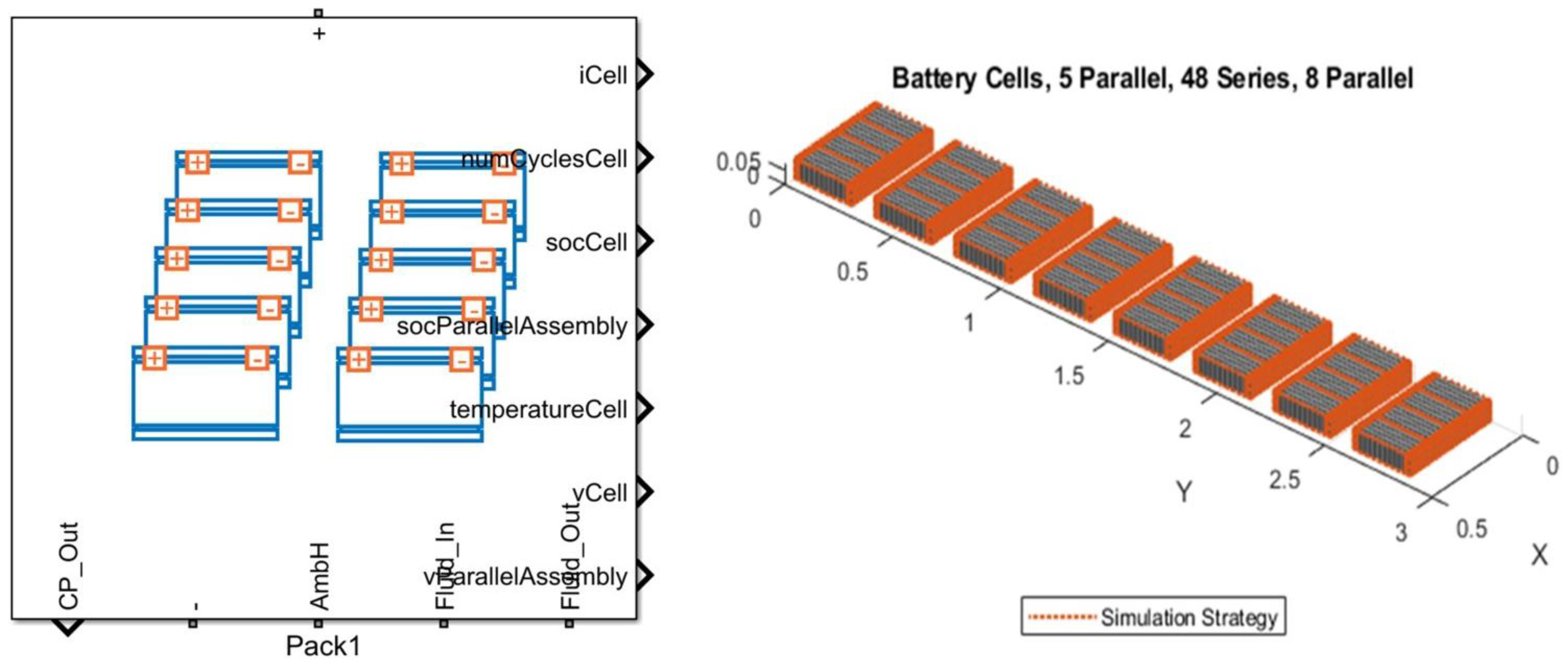
Figure 4.
Cylindrical battery parametric layout sizing.
2.3. Simulation-Based Optimization
This approach establishes simulation-driven parametric optimization [10,11] for the thermal management efficiency of an electric aircraft battery pack under defined mission loading conditions. The goal is to identify the optimal combination of thermal system parameters that reduces peak cell temperature and thermal non-uniformity.
h, min,Max]. Objective function: Thermal loss is defined as J ()that penalizes both high peak cell temperature and a large intra-pack temperature gradient :
Weight factor balances the two terms, , . The optimization problem incorporates temperature safety constraints under RTCA DO-311A and ASTM F3338 standards [7,8,9].
Each design variable is evaluated by numerically solving the transient energy balance for each battery cell by the following equation:
, , V=cell volume, A=cooling surface area, , cond, i, =conductive heat exchange with adjacent cells. The Simscape-based model logs cell temperatures over the mission profile and are extracted post-simulation.
2.3.1. GA+SPSA Optimization Strategy
The design space is initially examined using a genetic algorithm (exploration), which employs stochastic operators to evaluate various potential thermal regions. A population size of 30, a crossover fraction of 0.8, a mutation probability of 0.05, and a termination condition of 50 generations were applied across CPU cores to accelerate convergence.
GA identifies promising parameters that are subsequently improved through simultaneous perturbation stochastic approximation (SPSA). This method of exploiting gradient-free stochastic optimization approximates the gradient with just two simulation evaluations for each iteration.
The optimization objective function is defined as:
subjected to variable bounds for cell spacing, coolant plate sizing, and thermal module heat distributions.
Random perturbation It is generated, and the simulation is run at . The gradient estimate is formed as;
Parameters are updated according to
Where and Are diminishing step size sequences. Convergence criteria: The Genetic Algorithm (GA) aims to achieve a fitness level below 0.001 within 10 generations. SPSA adjusts parameters within 100 iterations, utilizing a parallel computing toolbox.
Figure 5. A schematic overview of the design parameter optimization framework for battery thermal management. The framework begins with a problem-based formulation that includes performance objectives and design constraints.
Thermal modules undergo testing under specific mission loading conditions using test-rig setups. The results of these simulations help evaluate thermal and performance metrics, informing the iterative design optimization process.
2.4. Boundary Conditions

Table 1.
Boundary conditions.
| Interface | Conditions |
| Internal heat | I = 35-45A, R = 20-30mΩ |
| Cell plate contact Cooling plate to ambient Edge cells to ambient Plate to coolant Thermal plate heat transfer |
R_contact=0.01-0.1 K/W h=5-25 W/m2k h=10W/m2k, ∈=0.85 h_fluid=100-5000 W/m2.k 5 ≤ h ≤ 30W/m2k |
2.5. Simulated Thermal Modules
Figure 6 illustrates that the battery model can be configured to different levels of granularity. All cells in a module can either be considered to have the same thermal conditions or expanded to include cells with distinct conditions, such as treating the cells on the edge of the module assembly differently, as they have a larger surface area exposed to the ambient environment via the pack housing. Each assembly consists of four modules, each having a single thermal connection to the ambient and an array of independent thermal connections to the cooling plate. The arrays of thermal connections to the cooling plate are combined into a single array, which is then connected to the cooling plates.
3. Test Rig Approach
3.1. BESS Test Rig
The battery energy storage system (BESS) testing module simulates a test rig for an electric aircraft’s entire battery energy storage system using a load case simulation strategy. This setup enables quick exploration of battery and cooling system designs. In this context, the battery’s drawn current over time is referred to as a load case. The battery model provides various granularity settings, and it is also possible to configure the simulation of the cooling plate at different levels of accuracy and granularity. This is illustrated in the figure below.
The battery’s current is drawn over time when under a load. The current measured during a mission in the primary model serves as the foundation for determining current draw. The battery model includes various settings for granularity. Figure 8 shows that cells within a module can either be assumed to experience the same thermal conditions or may consist of additional cells with specific conditions. For example, edge cells in the module assembly may be treated differently due to their heightened exposure to the environment through the pack housing. Moreover, the pack offers options associated with the cooling system. Some configurations treat the cooling system as a boundary condition, modeling it in a more abstract manner. The detailed edge conduction module, simplified boundary condition (lumped), uniform heat distribution module, and peripheral heat transfer module correspond to their respective methodologies or simulation techniques.
Table 2.
Module-level configuration.
| Optimized Module | Complexity | Accuracy | Granularity | Thermal behavior |
| a)Lumped | Low | Moderate | Low | Uniform temperature across the entire module |
| b)Edge | Moderate | High-moderate | Medium | Edge cells, heating, and ambient effects |
| c)Edge detailed | High | High | High | High fidelity inner cells with asymmetric cooling design |
| d)Detailed | Very High | Very High | High | Asymmetric thermal mapping with even heat transfer |
3.2. Thermal Module Test Rig
This method presents a new test rig for assembling battery modules, specifically one of the eight sub-packs within an electric aircraft battery pack. It facilitates a quick investigation into the design of the battery and the cooling system. In this model, the load case for the battery is represented by the current drawn from it over time, which is determined from current measurements taken during a mission in the main model.
The battery model allows configuration for different levels of granularity. All cells within a module are typically assumed to have identical thermal conditions; however, this assumption can be modified. For example, we could differentiate the cells at the edges of the module assembly due to their larger surface area exposed to the ambient environment through the pack housing.
The cooling plate can be represented with varying degrees of detail and precision. The most basic model considers the plate as a boundary condition, outlining the temperature gradient across the module. In contrast, the cooling plate can also reflect fluid movement through channels, and by adding more thermal elements to the plate, a more refined temperature gradient can be achieved.
Figure 9 illustrates a thermal module simulation test rig module design that generates a load case for the battery based on the current it delivers over time. This current load is derived from measurements taken during a mission within the main model.
4. Results and Validity Analysis
4.1. VTOL Mission Results with Thermal Modules
In the initial mission, a lumped battery simulation was conducted. The figure below displays altitude, air speed, and electrical readings obtained from a single simulation as the electric aircraft ascends to cruising altitude and continues to fly until the battery reaches a 30% state of charge. The consistent power levels for auxiliary systems, including avionics, lighting, and heaters, reflect predictable energy requirements, which aid in determining battery size and planning the mission. The slight power decline over time suggests minimal voltage sag or adaptive efficiency, underscoring the need for effective thermal management to support continuous loads and prevent overheating.
With a state of charge of 70%, the range in performance metrics increases by 3.64% when using a detailed thermal module battery compared to a lumped module, and there is a 2.67% increase when using an edge module.
Figure 11.
State of charge and voltage levels.
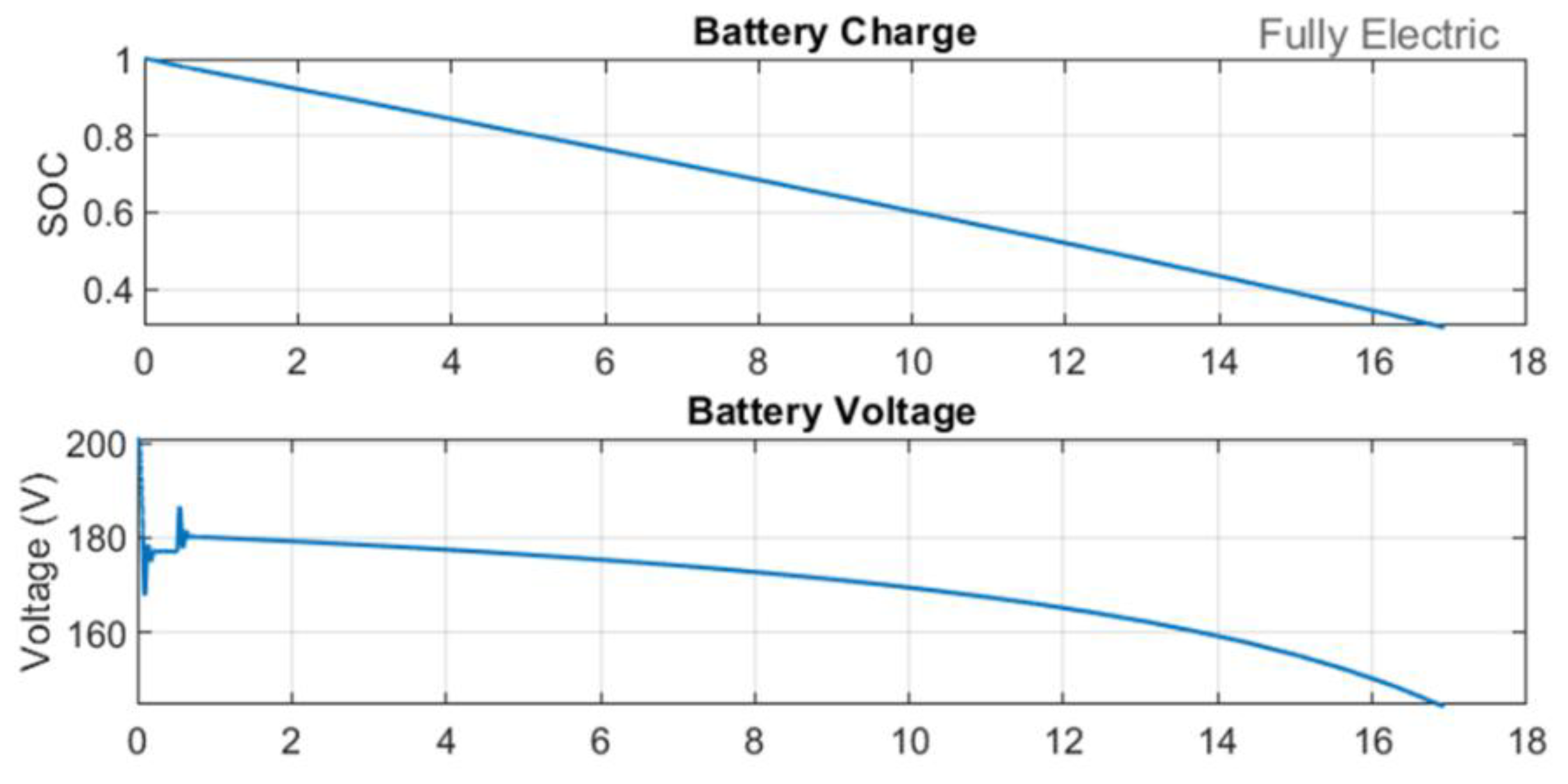
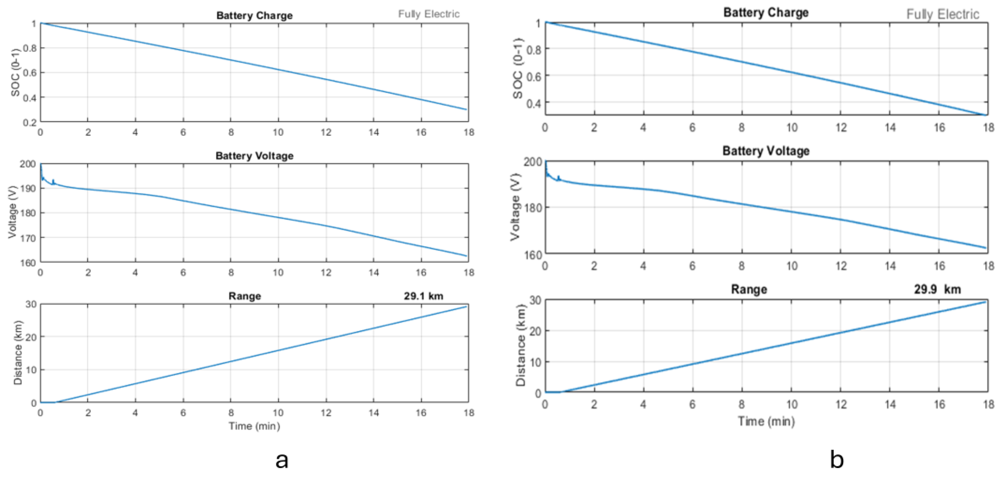
Figure 12.
a) Edge module b) Detailed module mission metrics.
4.1.1. Battery Capacity and Payload Trade-Offs
The plot below illustrates how battery capacity and payload affect the aircraft’s flight range: a) Using data from the datasheet (Molicel INR_21700_P45 B)[12], a module with an energy density greater than 240 Wh/kg is selected and its parameters are specified. This module is scaled up to create a battery pack with enough cells in series to meet the voltage requirements and enough cells in parallel to fulfill the capacity demands. When carrying an 80 kg payload, the flight range exceeds 15 miles.
b) The module analysis establishes a 200 Wh/kg battery energy density. The relationship between battery size and range is nonlinear, indicating that the aircraft’s total weight increases as battery capacity grows. Nearly half of the assessed design space allows for a flight range greater than 25 km (15.5 miles).
Figure 13.
Battery capacity and payload trade-offs.
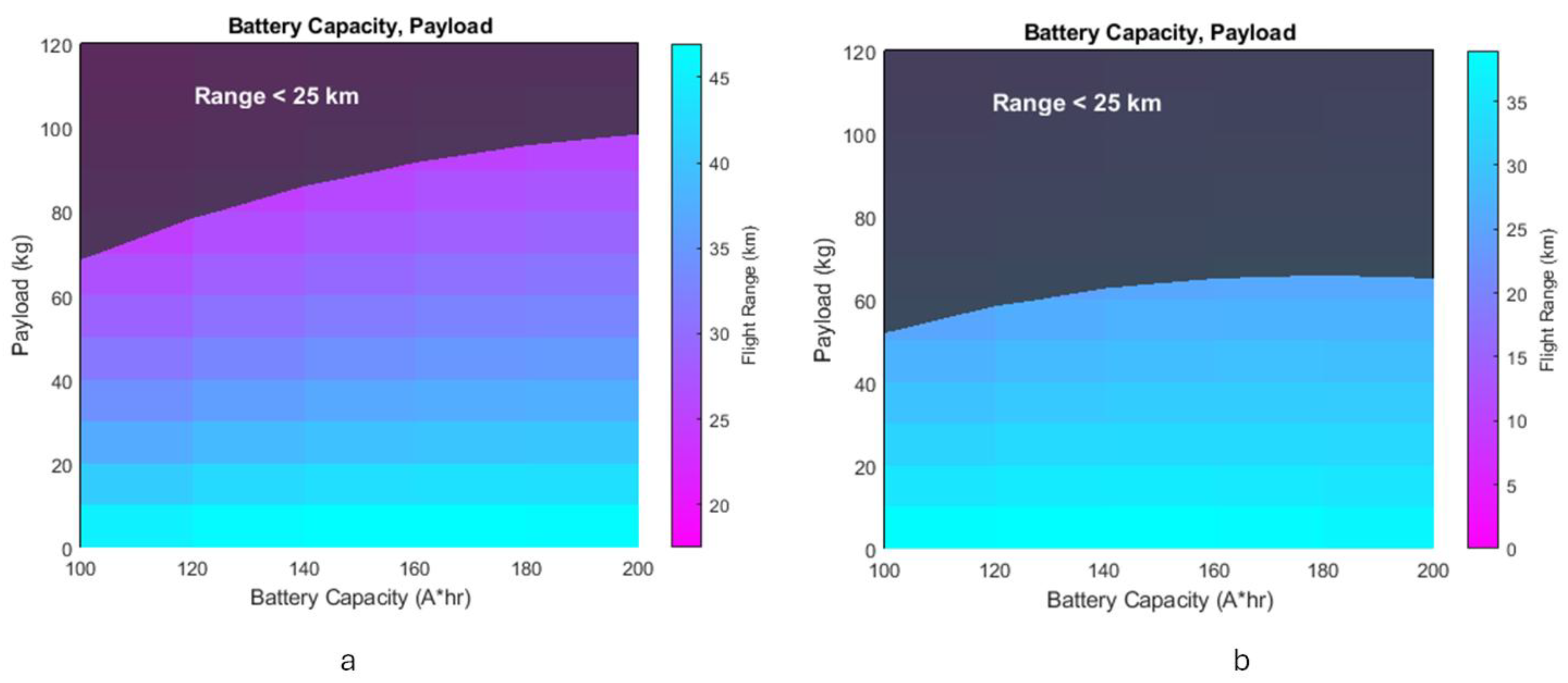
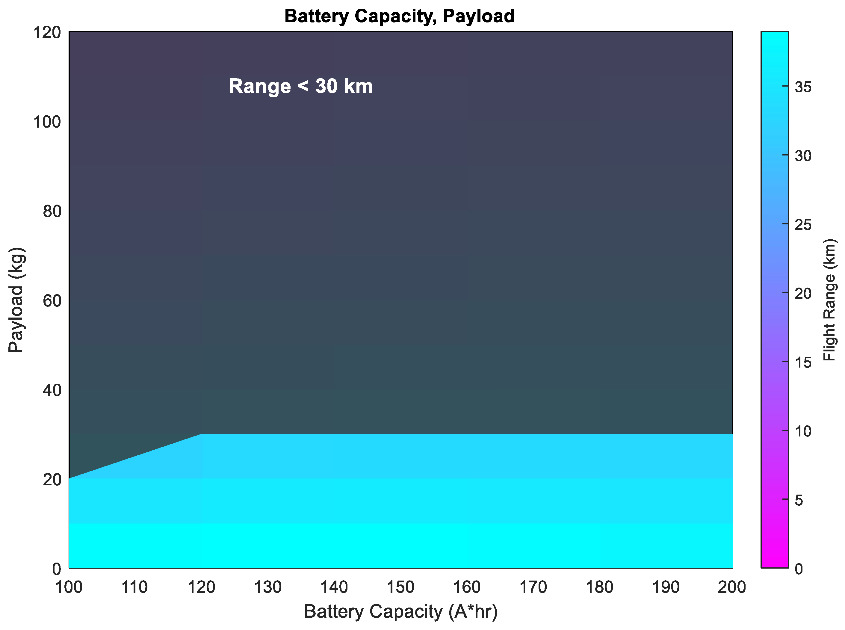
Figure 14.
Extra range battery capacity vs payload trade-offs.
4.2. Test Rig Results
The test rig module subsystem displays connected sub-packs and cooling plates as illustrated in Figure 15 below. This testing method assumes that all cells in each module operate at a uniform temperature. The findings reveal a well-balanced and stable electric propulsion system, with each motor drawing consistent currents (approximately 35-40 A) after initial fluctuations.
This consistency is crucial for maintaining flight stability and achieving thrust symmetry. 8 battery packs are constructed using the selected battery module. Coolant circulates through channels in a cooling plate that has parallel pathways. The same mission tracks the temperatures of the battery cells to ensure they remain below the maximum limit of 45°C, allowing for a maximum temperature difference of 5°C between cells.
Figure 16.
Module assembly thermal metrics.
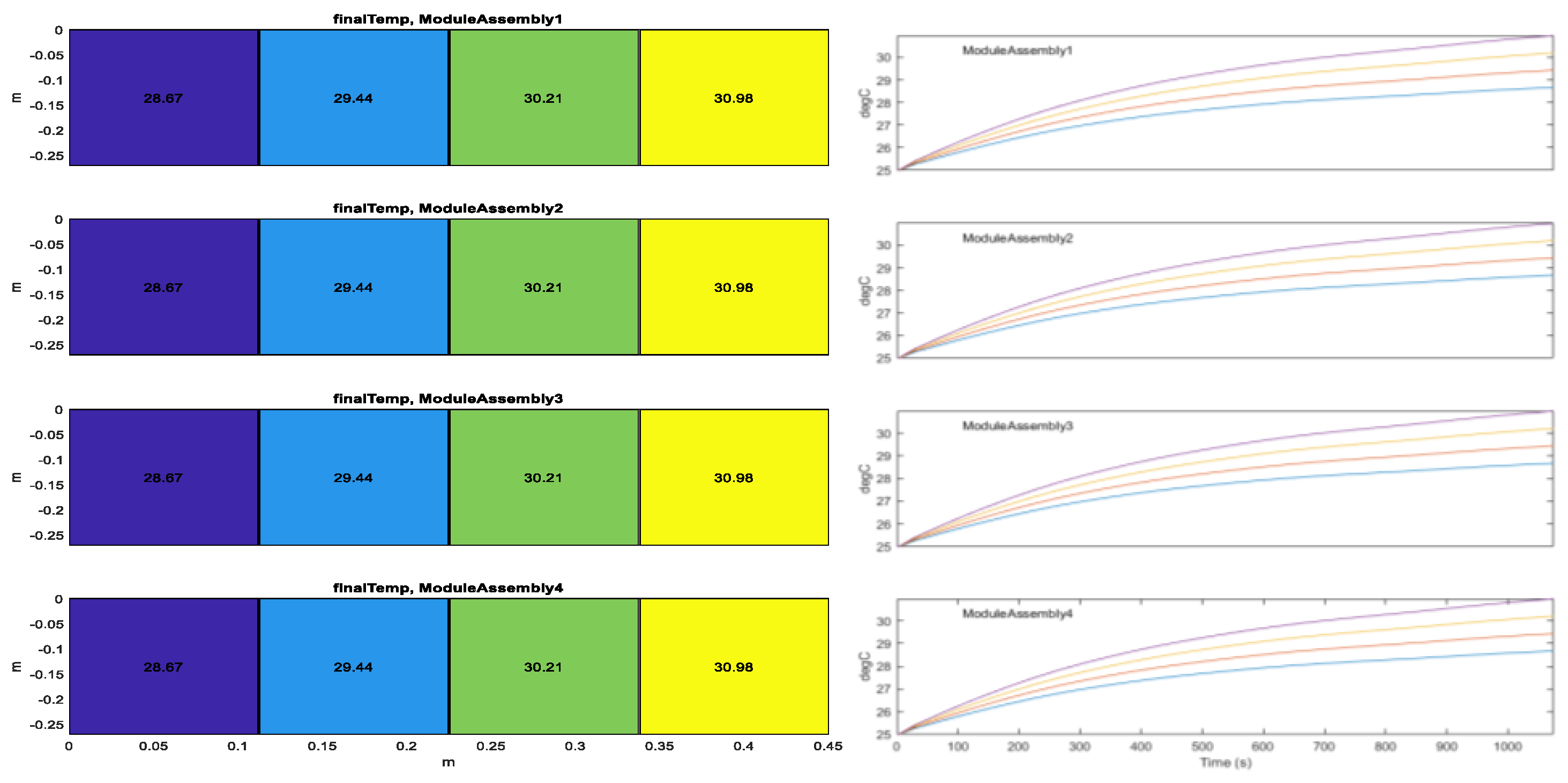
Figure 17.
Temperature test rig analysis.
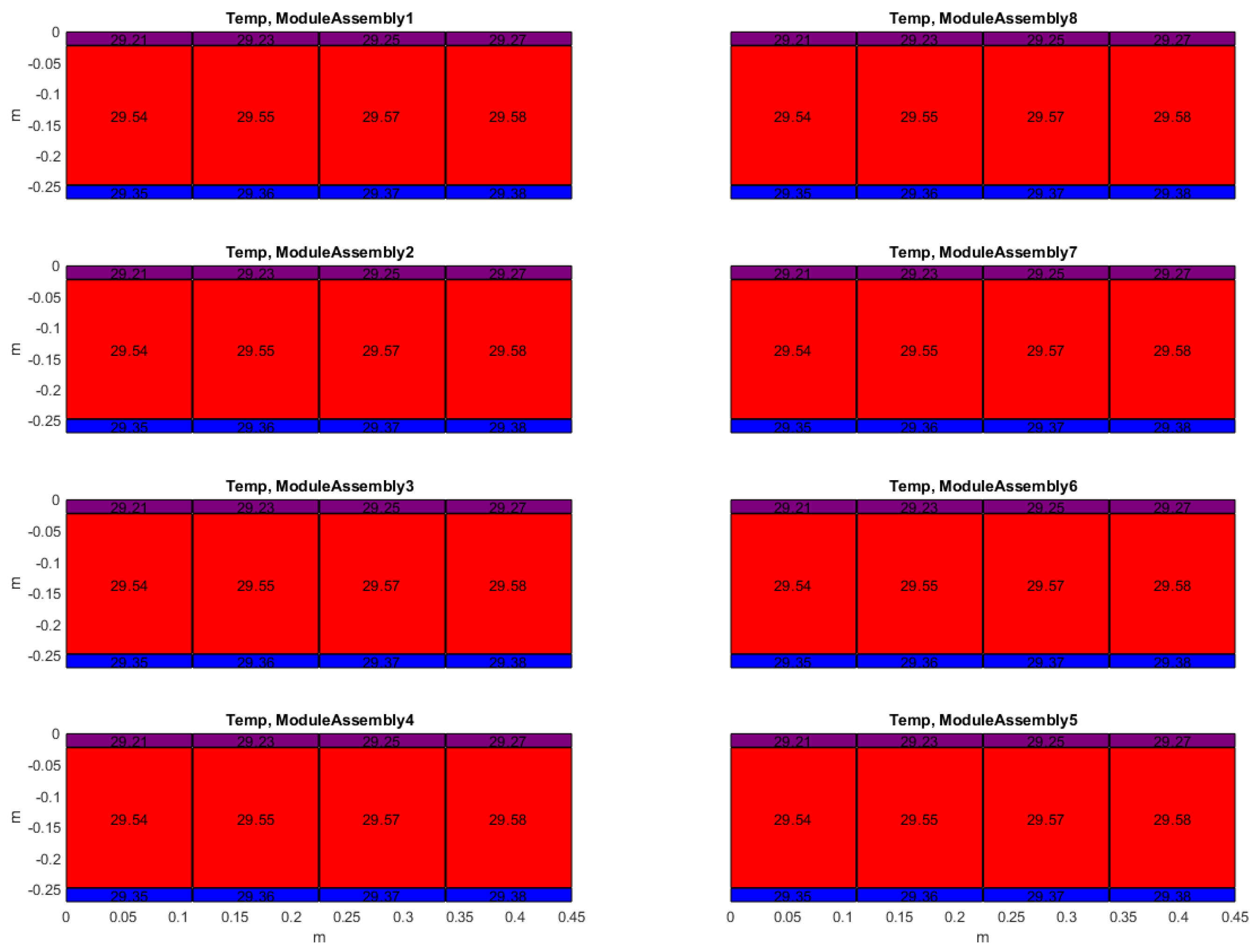
Figure 18-19 below illustrates the test results of the edge module assembly cooled by fluid circulating through a cooling plate. The cells located at the edges of the module assembly are considered a separate group with different thermal conditions compared to the interior cells. The parameters of the cooling system can be adjusted until the cell temperatures fall within the specified range.
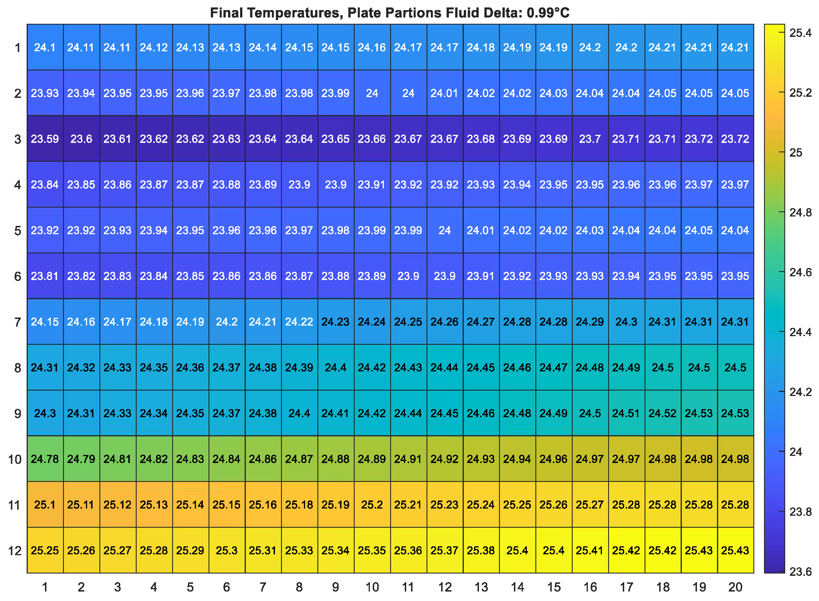
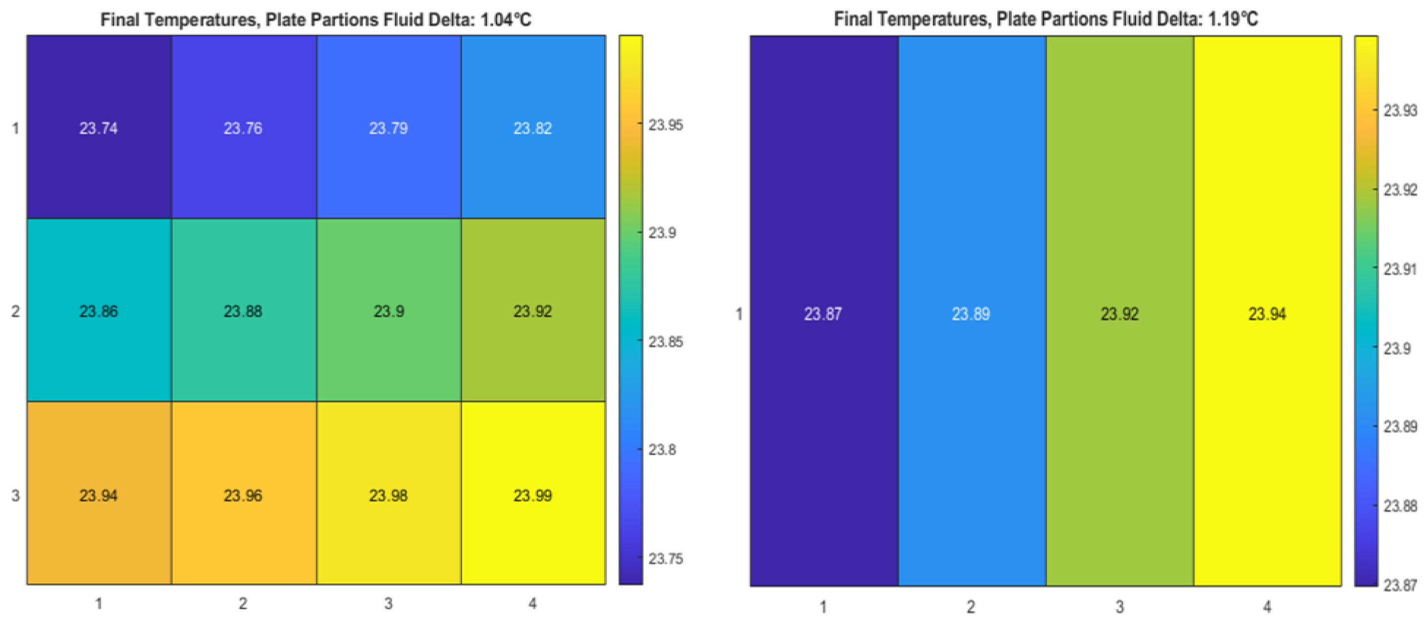
The heat map below illustrates the outcomes of a test conducted with the detailed module assembly, which was cooled through fluid flow in a cooling plate. Each cell in the module assembly is modeled with distinct thermal conditions. The thermal system is fine-tuned until the cell temperatures fall within the desired range.
Figure 20.
Heatmap analysis.
5. Conclusions
This paper presents a practical method for exploring the design space of battery thermal management in electric vertical take-off and landing (VTOL) aircraft. The simulation results exhibit strong performance under a fully electric mission load by adopting an optimization model approach. The proposed thermal management test rig approach further validates the feasibility of this research idea for engineering applications.
This study was conducted in three main steps:
1) To simulate the control dynamics of the battery thermal strategy, a comprehensive model of the electric aircraft powertrain network was created, grounded in Newtonian mechanics and utilizing the Simulink toolkit with a model-based method.
2) The concept of designing optimization problems using GA and SPSA methods has been presented. The parameter sweep technique is applied in thermal module simulations to enhance battery modules within specified limits. This strategy focuses on acquiring thermal and performance metrics throughout the simulation processes.
3) The BESS and thermal module test rig approaches were proposed to explore the feasibility of the design space for battery thermal management ideas in engineering implementations. The simulation results indicate that dynamic thermal management control operates within the optimized required range.
The results of this study demonstrate significant advancements in model-based battery thermal management approaches for electric vertical take-off and landing (VTOL) aircraft, aligning well with previous research that emphasizes the critical role of temperature control in lithium-ion battery performance and safety. The observed improvements, such as a 3.64% performance gain achieved through detailed thermal module modeling and a 22% reduction in peak temperature via active cooling strategies, confirm the hypothesis that integrating detailed thermal modeling with system-level optimization can enhance thermal uniformity and mitigate risks associated with thermal runaway and capacity degradation. These findings extend a model-based framework that couples electrical and thermal behaviors with mission-specific optimization, addressing the limitations of earlier studies that often relied on steady-state or isolated thermal models. The use of combined Genetic Algorithm and SPSA optimization techniques further underscores the potential for efficient exploration of complex design spaces in aviation battery systems. Broadly, this research contributes to the growing field of urban air mobility by offering validated methodologies for lightweight, safe, and efficient battery thermal management, which is crucial for the scalability and certification of electric aircraft. Future research could expand on this work by incorporating real-time adaptive thermal control strategies, exploring alternative battery chemistries, and validating the models with extensive experimental data from flight tests to further enhance reliability and performance under diverse operational conditions.
Author Contributions
Conceptualization, M.W.; data curation, M.W.; formal analysis, S.Y.; methodology, M.W.; software, M.W.; supervision, S.Y.; validation, S.Y.; visualization, S.Y.; writing—original draft, M.W.; writing—review and editing, M.W. All authors have read and agreed to the published version of the manuscript.
Funding
This research received no external funding.
Data Availability Statement
The original contributions presented in this study are included in the
article. For further inquiries, please contact the corresponding authors.
Conflicts of Interest
The Authors declare that the research was conducted in the absence of any commercial or financial relationships that could be construed as a potential conflict of interest.
Abbreviations
The following abbreviations are used in this manuscript:
| BESS | Battery Energy Storage System |
| BTMS | Battery thermal management system |
| GA | Genetic Algorithm |
| SPSA | Simultaneous Perturbation Stochastic Approximation |
| VTOL | Vertical take-offs and landings |
| I | Current |
| R_contact | Contact resistance |
| h_fluid | Plate to coolant thermal transmittance |
| h | Heat transfer coefficient |
References
- Liang, S., Wu, X., Wu, Z., & Liu, W. (2025). Progress and Challenges on Materials Used to Optimize Flight Efficiency, Improve Safety and Reliability, and Reduce Cost of Electric Vertical Take-Off and Landing Aircraft. Journal of Applied Polymer Science, e57029. [CrossRef]
- Nyamagoudar, V., Namratha, P. R., Balasubrahmanyam, M., Vanka, S., Gattu, R., Abuheiba, A., & Jha, R. K. (2024). Hybrid Cooling System for Thermal Management in Electric Aerial Vehicles (No. 2024-26-0468). SAE Technical Paper.
- Gosavi, A. (2015). Simulation-based optimization (Vol. 62). Berlin: Springer.
- Bell, M. E., & Litt, J. S. (2020). An Electrical Modeling and Thermal Analysis Toolbox for Electrified Aircraft Propulsion Simulation. In AIAA Propulsion and Energy 2020 Forum (p. 3676).
- MathWorks. Modeling an electric propulsion system for eVTOL aircraft in Simulink. MathWorks.(2022).
- Simulink User’s Guide, The MathWorks Inc., revised for Simulink 10.7 (Release 2024b), 2024, URL: https://www.mathworks.com/help/pdf_doc/simulink/simulink_ug.pdf [Accessed Dec. 2024].
- RTCA DO-311A, “Minimum Operational Performance Standards for Rechargeable Lithium Battery Systems,” RTCA Inc., 2017.
- ASTM F3338-18, “Standard Specification for Electric Propulsion Battery Systems for Aircraft,” ASTM International, 2018.
- EUROCAE ED-276, “Minimum Operational Performance Standards for VTOL On-Demand Mobility Aircraft,” EUROCAE, 2020.
- Roberts, J. J., Cassula, A. M., Silveira, J. L., Prado, P. O., & Junior, J. C. F. (2017, November). Gatoolbox: A MATLAB-based genetic algorithm toolbox for function optimization. In The 12th Latin-American Congress on Electricity Generation and Transmission–Clagtee.
- Spall, J. C. (2002). Implementation of the simultaneous perturbation algorithm for stochastic optimization. IEEE Transactions on aerospace and electronic systems, 34(3), 817-823. [CrossRef]
- E-One Moli Energy Corp. INR-21700-P45B high power lithium-ion rechargeable cell data sheet. (2021).
Figure 1.
Electric aircraft VTOL dynamics model.
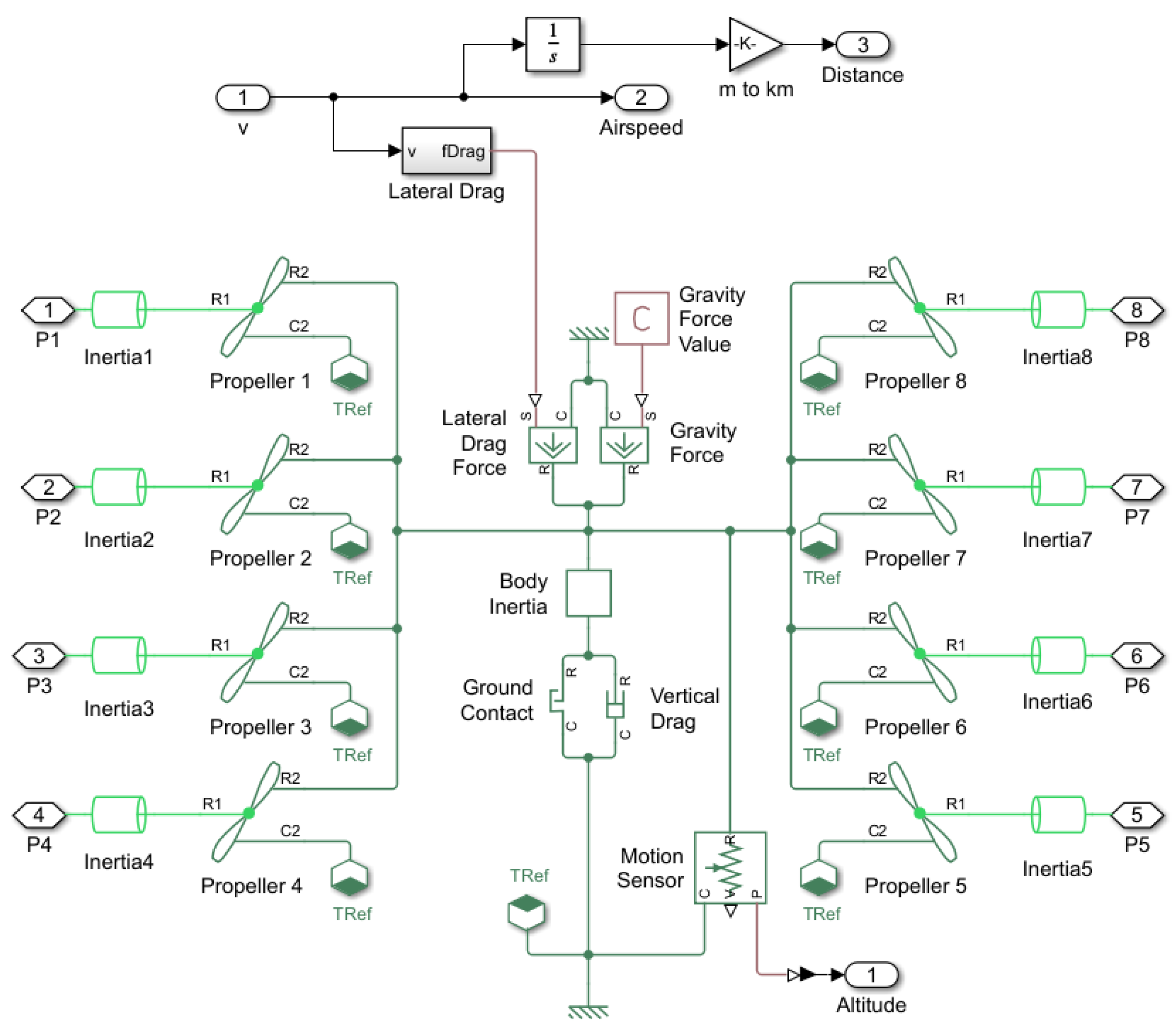
Figure 2.
Conceptual VTOL power network.
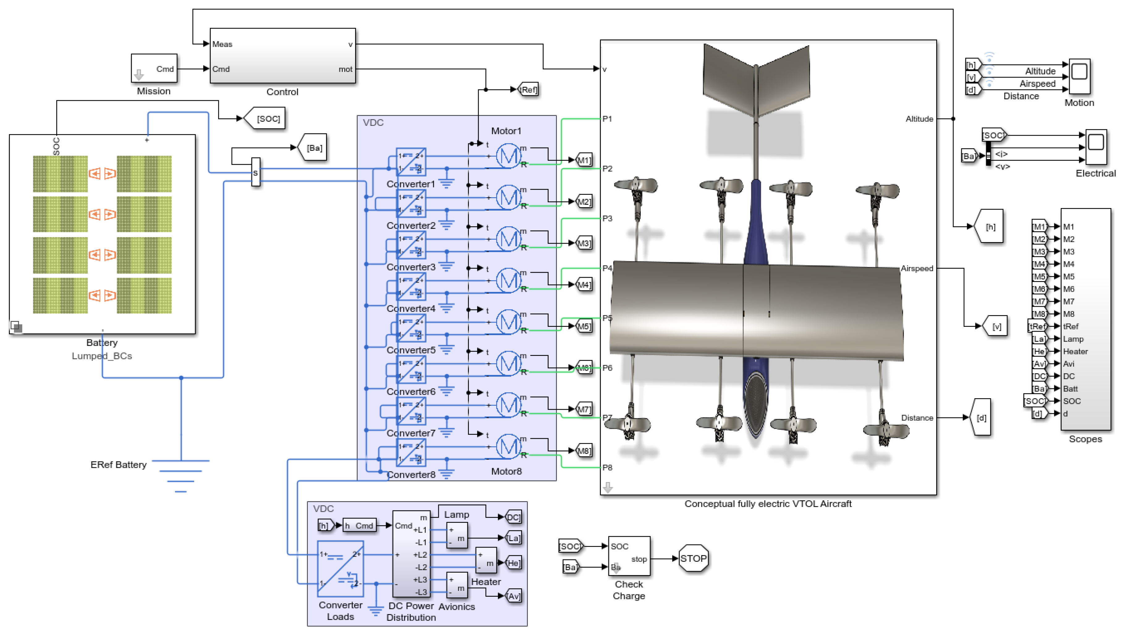
Figure 5.
Optimization framework.
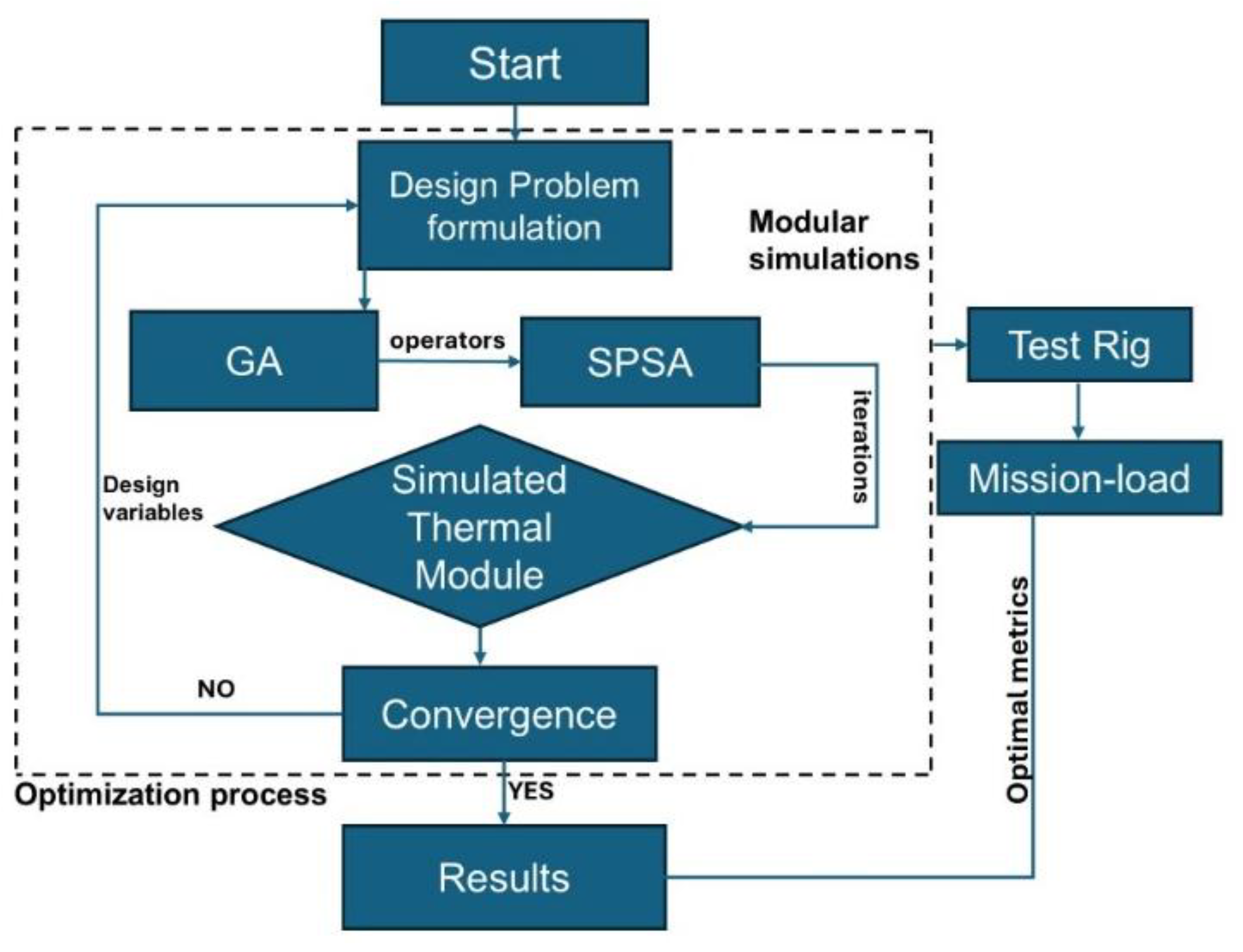
Figure 6.
Simulated thermal modules.
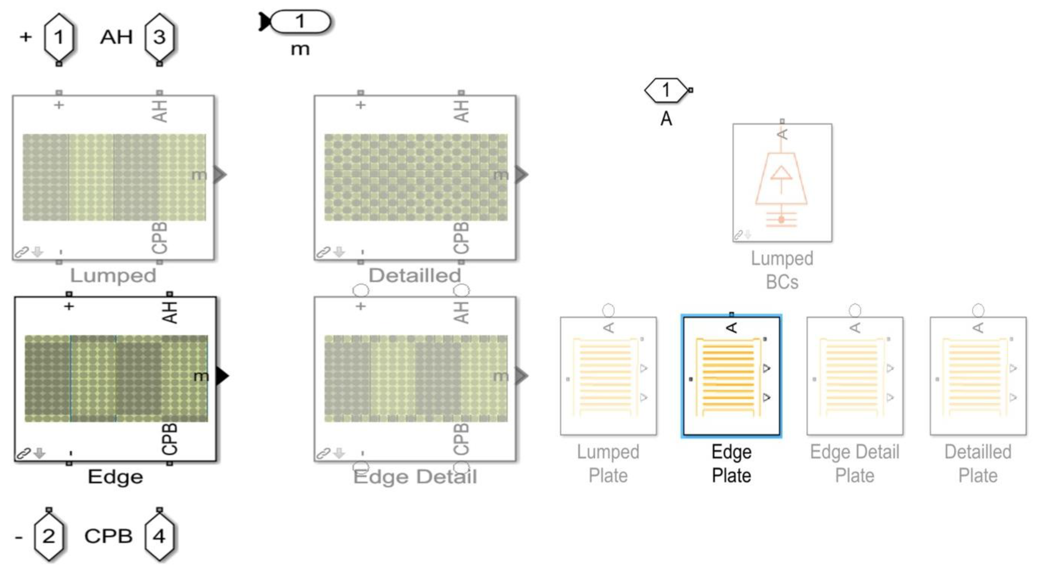
Figure 7.
BESS simulation test rig.
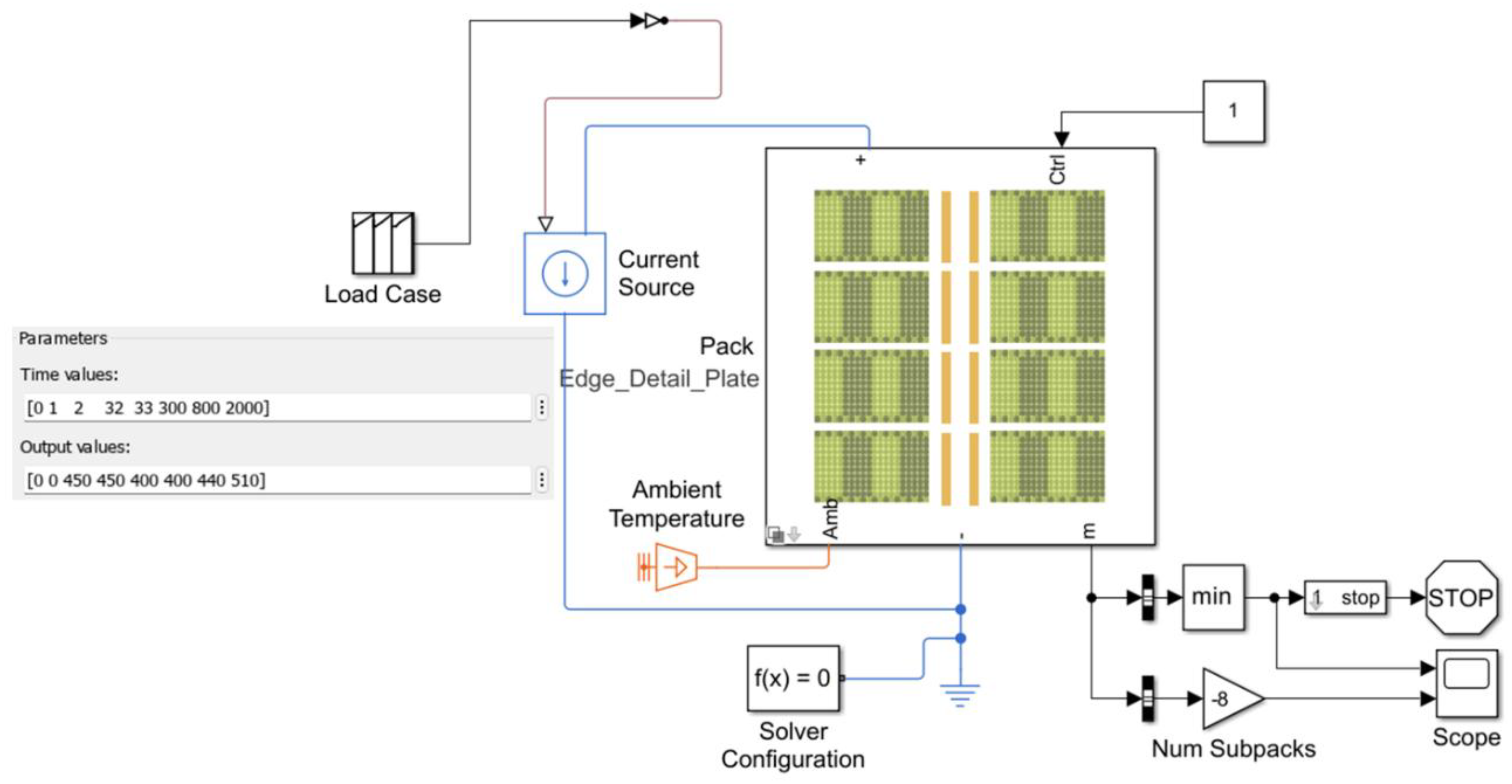
Figure 8.
Battery module configurations.
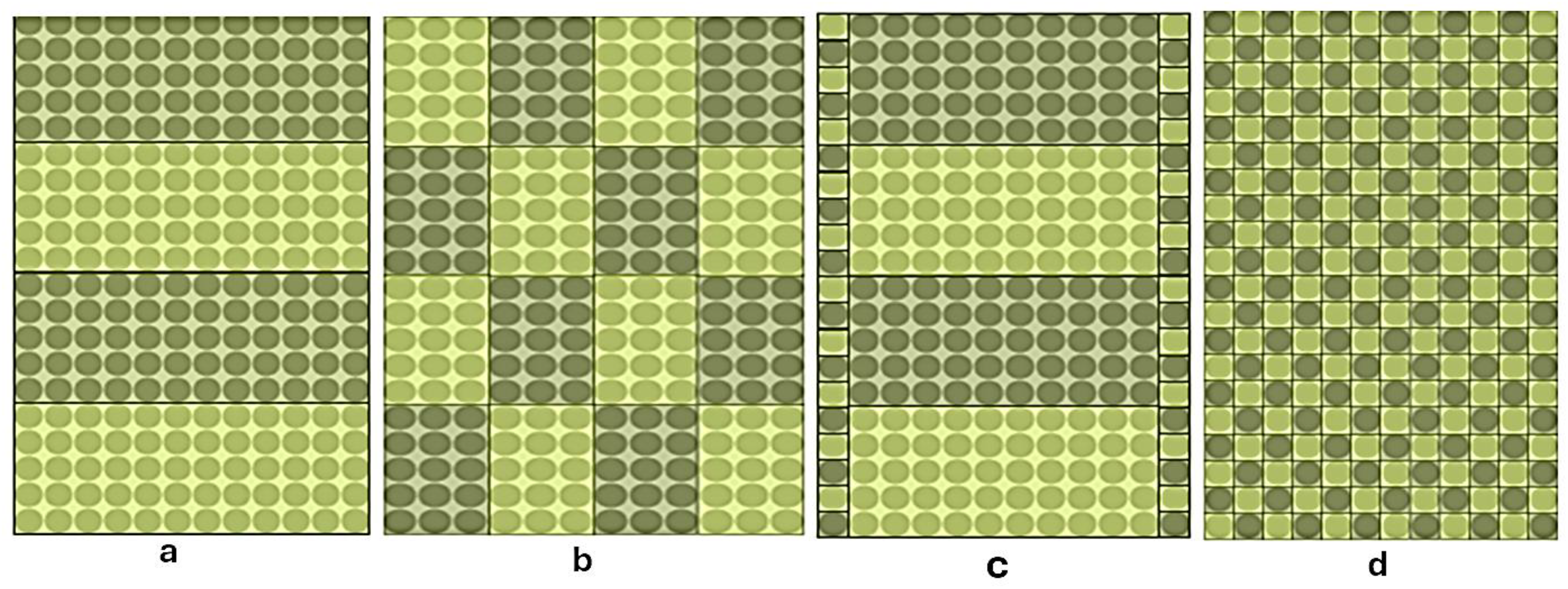
Figure 9.
Thermal module simulation test rig.
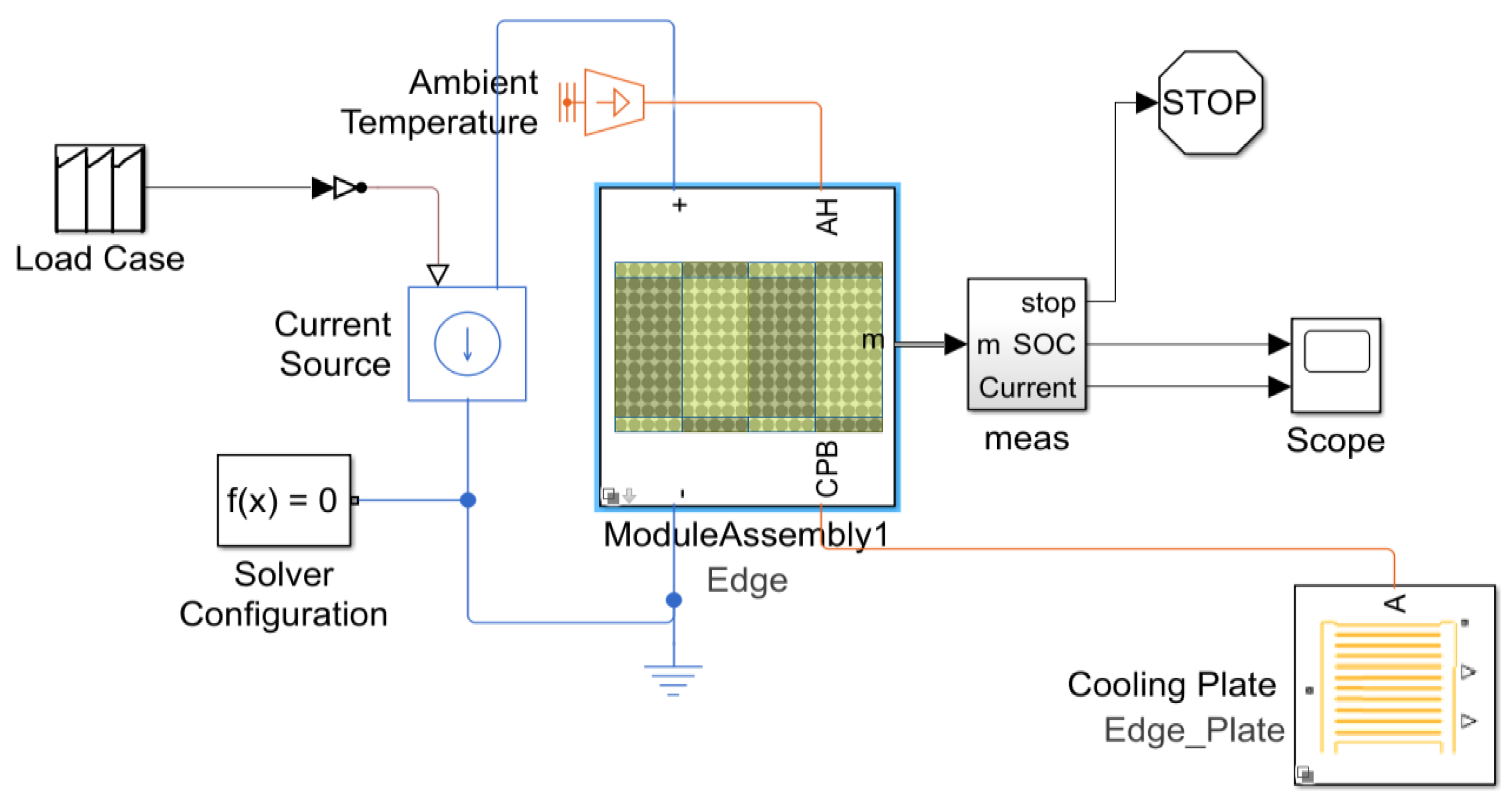
Figure 10.
Current and power levels.
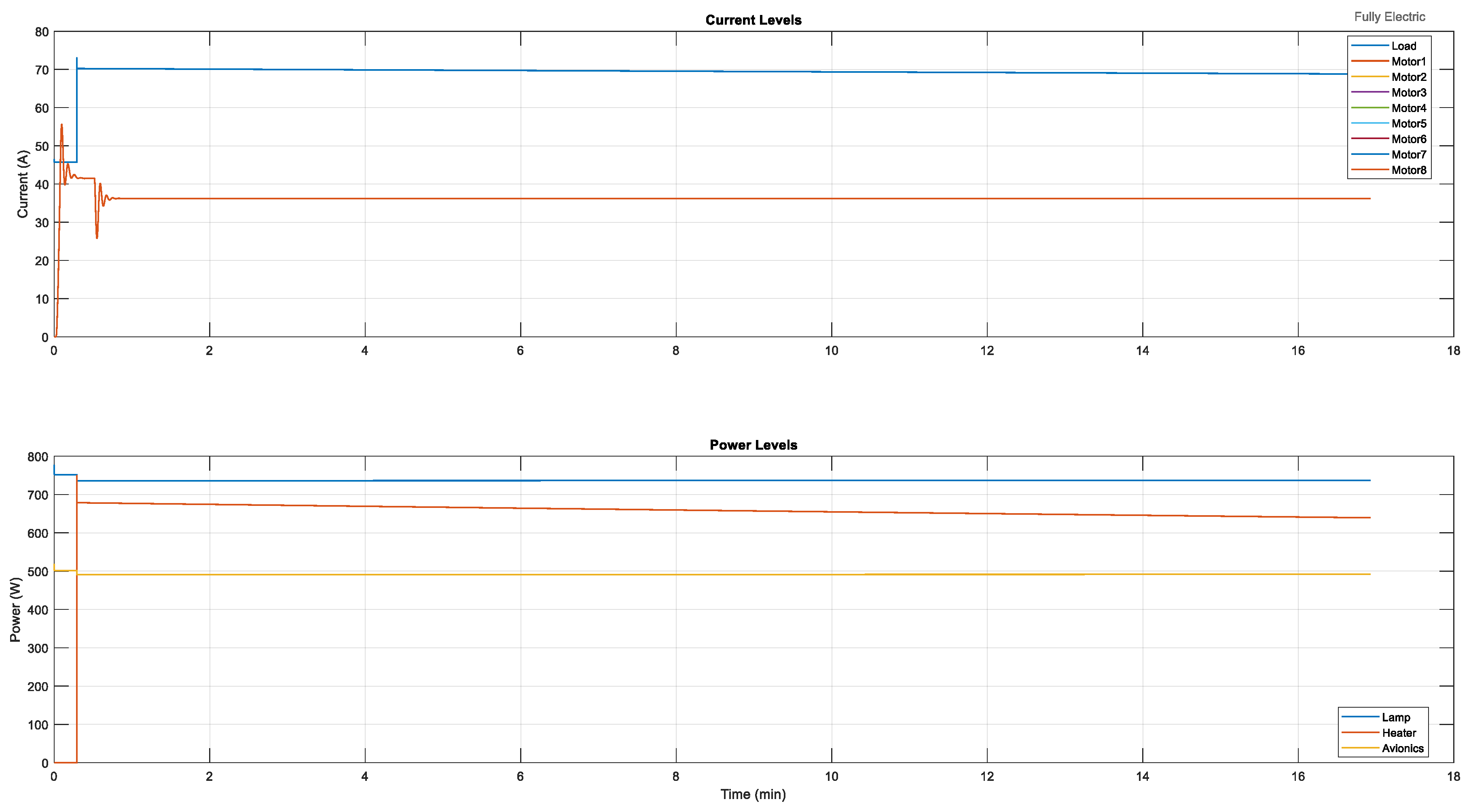
Figure 15.
Test rig module assembly.
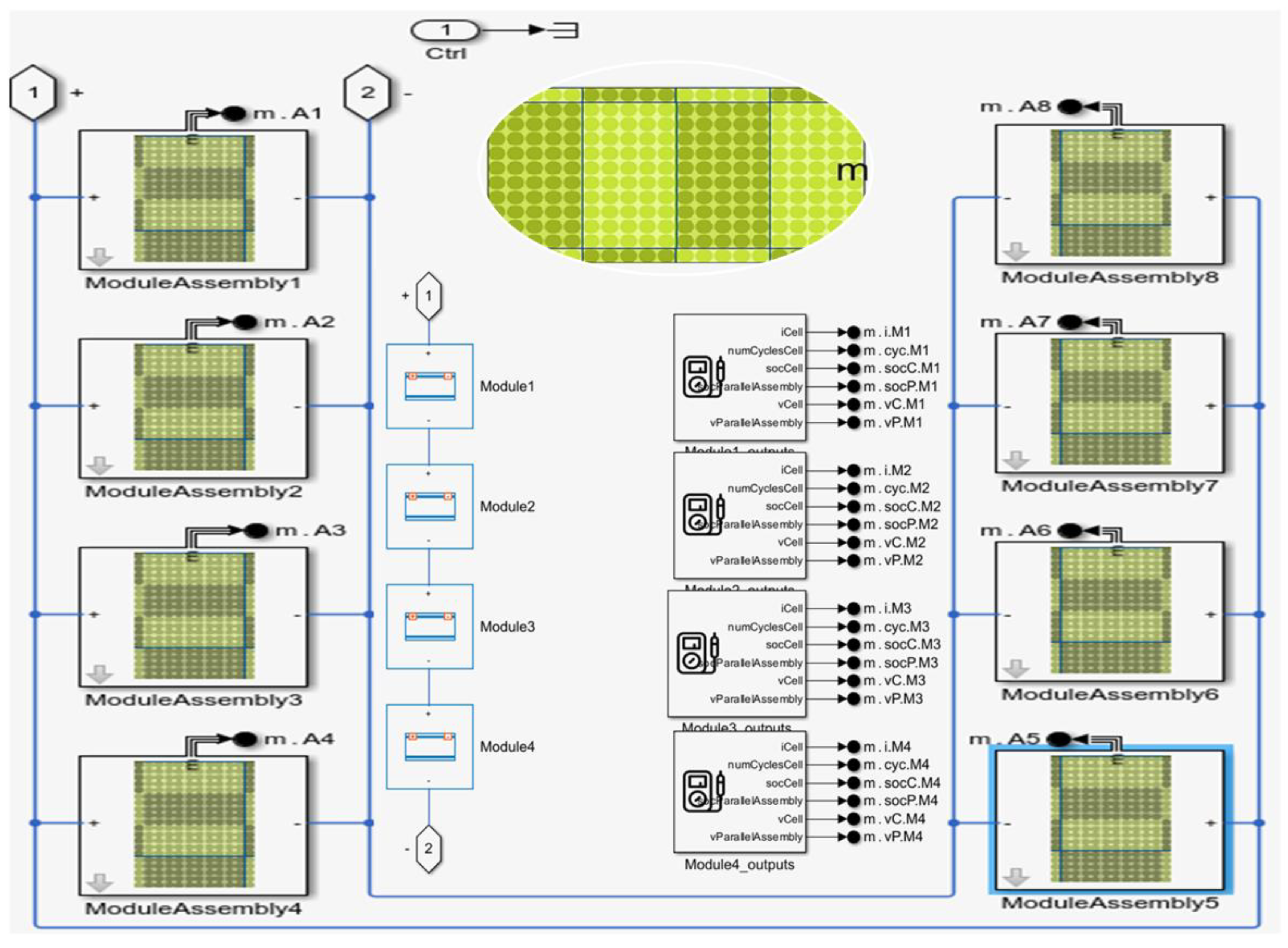
Figure 18.
Cell final thermal metrics.
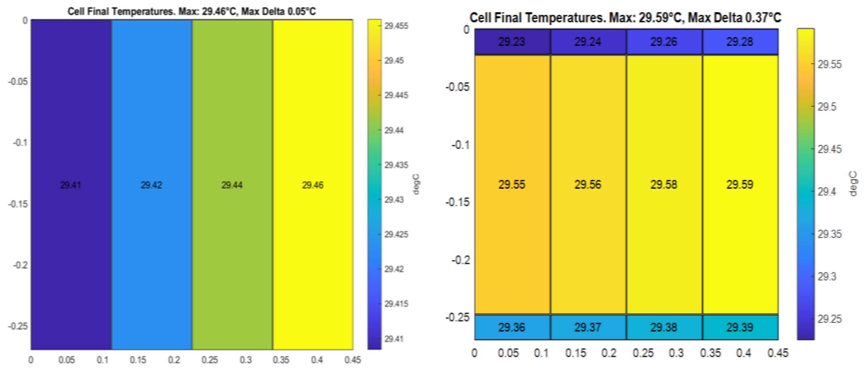
Figure 19.
Final thermal metrics.
Disclaimer/Publisher’s Note: The statements, opinions and data contained in all publications are solely those of the individual author(s) and contributor(s) and not of MDPI and/or the editor(s). MDPI and/or the editor(s) disclaim responsibility for any injury to people or property resulting from any ideas, methods, instructions or products referred to in the content. |
© 2025 by the authors. Licensee MDPI, Basel, Switzerland. This article is an open access article distributed under the terms and conditions of the Creative Commons Attribution (CC BY) license (http://creativecommons.org/licenses/by/4.0/).
Copyright: This open access article is published under a Creative Commons CC BY 4.0 license, which permit the free download, distribution, and reuse, provided that the author and preprint are cited in any reuse.


