
Submitted:
21 June 2025
Posted:
23 June 2025
You are already at the latest version
Abstract
A literature review about polymer composites reveals that the natural fibers have been widely used as a reinforcement phase during the recent years. In this framework, the lignocellulosic fibers have received marked attention because of their environmental, thermomechanical and economic advantages for many industrial sectors. This research aims to identify the impact behavior of ramie reinforced epoxy composites with medium and high volume fractions of fibers in intact (nonaged) and aged conditions as well as to analyze if the influence of interface quality on the impact fracture energy can be described by a novel mathematical model. To reach these objectives, the study is designed with three groups (40%, 50% and 60% of fiber theoretical volume fractions) of intact specimens and three groups of aged samples by condensation and ultraviolet radiation (C-UV) simulation containing the same fiber percentages. Consecutively, impact strength and fracture surface analyses are done to expand the comprehension of the damage mechanisms suffered by the biocomposites and to support the development of the mathematical relation. Certainly, this novel model can contribute to more sustainable and greener industries in the near future.
Keywords:
Damage Analysis
; Natural Fiber Polymer Composite
; Interface Quality
; Impact Fracture Energy
1. Introduction
In the recent decades, the polymer composites reinforced with natural fibers have been widely studied due to their eco-friendly and sustainable characteristics. Additionally, advantages like abundant resources, low acquisition cost and suitable thermomechanical properties make them even more attractive for automotive, energy, aerospace and civil construction sectors [1,2,3,4,5,6,7,8,9,10,11,12,13,14].
The replacement of some traditional materials used in different industries by biocomposites can make them more competitive, sustainable and greener [15,16,17,18]. Nevertheless, in various these applications, the impact loadings are critical for the structural safety of many components, therefore, it is essential to study the impact behavior and its consequences on these multiphase materials.
A literature review of natural fiber reinforced polymer composites presents a representative lack of research regarding the mechanical behavior of these multiphase materials with medium and high volume fractions. At the same time, it easily presents that the influence of interface quality on the mechanical performance and, consequently, in the fracture behavior of laminates is a well-established fact [18,19,20,21].
Basically, the intralaminar fracture consists of matrix and fiber consecutive ruptures, however, between these two composite phases there is an interface, for that reason, the failure mechanism can be stated as a matrix-interface-fiber successive rupture (path 1-1’, Figure 1). Differently, the interlaminar fractures are characterized by delaminations (path 3-3’, Figure 1), in other words, an interlayer separation. In general, a combination of these failure mechanisms can occur in a laminate when it is subjected to a loading (path 2-2’, Figure 1) [22,23].
In conformity with all this context, the objectives of this research are to characterize the impact behavior of ramie woven fabric reinforced epoxy composite with medium and high volume fractions in intact and C-UV aged conditions and to investigate whether a novel mathematical relation is able to represent the influence of the interface quality on the sort of cracking process and its impact fracture energy.
In summary, the methodology of this research uses the experimental data of the performed Charpy tests and the pertinent descriptive and inferential statistical analyses. In addition, fracture surface characterizations, the laws of classical thermodynamics, the concept of Hamilton’s principle and literature data are used to obtain the results and to support the study’s conclusions.
Ultimately, the novel relation obtained describes how the interface quality influences on the kind of fracture phenomenon and on the impact fracture energy of the tested biocomposites. Obviously, this fact the can hold up technological developments in view of more sustainable and greener engineering components.
2. Materials and Methods
2.1. Production of Biocomposite Plates
The first process was to determine the density of ramie fiber in the acquired woven fabric using four pycnometers based on ISO 4787 [24]. Ten measurements were made in each pycnometer and the mean obtained (ρ is in congruence with literature values, for example, as calculated by Uppal et al [25]. That result has been used to determine the number of ramie woven fabric plies for 40%, 50% and 60% of fiber theoretical volume fractions (see Table 1) according to the rule of mixture and mold volume
The exposure of ramie woven fabric plies in a stove during 24 hours at 60° was made to remove moisture from them. Successively, a blend of epoxy resin (DGEBA/TETA MD 130) and hardener (FD 129) was done manually during 3 minutes in a mass ratio of 1:0,13. After applying vaseline (demolding agent) in the mold, the ramie woven fabric plies were stacked in it with the cited blend. In sequence, a hydraulic compression process was used (6000 kgf/cm², corrected during 20 minutes) to shape the plates. Finally, one day after that, the biocomposite plates were removed from the mold.
For this study were considered six plates, three (40%, 50% and 60% of fiber theoretical volume fractions) for intact specimens and three for C-UV aged specimens using the same reinforcement percentages, as can be seen in the next section.
2.2. Impact Tests and Statistical Analyses
The Charpy impact tests have been performed according to standardization ISO 179-1[26] with intact and C-UV aged specimens (Figure 2) using a manual impact test machine and a 25 Joules hammer. Specifically, the experiments have been designed with the three groups (40%, 50%, 60%) of called intact specimens and the same number of groups for the aged ones [27].
For the C-UV aging process was used an accelerated equipment of ADEXIM-COMEXIM manufacturer according to ASTM-G53/154 [28]. The simulation conditions were set up based on ASTM 5208 [29] and ADEXIM-COMEXIM correlation [30]. The aged settings regarding this correlation were 504 hours of exposure at 70 °C in a cycle of 8 hours. Hence, this accelerated simulation was equivalent to 9 months of real exposure, approximately [27].
The descriptive statistics of experimental data and graphs were made using Origin 6.0 software and the inferential analysis has been performed in PAST 4.03 computational tool. Non-parametric inferential tests were necessary to compare the impact strength values obtained for intact and aged groups because the Shapiro-Wilk normality test did not confirm a normal distribution for the experimental results considering all groups. In accordance with this fact, the Kruskal-Wallis and Dunn’s post hoc tests were firstly performed and, finally, the eta square calculation was developed.
2.3. Intralaminar and Interlaminar Fracture Characterizations
Some typical fracture surface characterizations were obtained using the Scanning Eletron Microscope (SEM). Firstly, a marked intralaminar fracture surface of the intact specimen number 2 (40% group) was analyzed at 45x, 120x, 300x and 700x of magnification. In addition, a delaminated surface region of the specimen number 8 (60% group) has been observed at 20x, 36x, 100x, 300x of magnification. These characterizations are relevant for the research because they reveal some specific differences between intralaminar and interlaminar damage mechanisms according to the strong or weak matrix-fiber adhesion (high or low interface quality), as shall be seen further.
It is important to note that, once the intralaminar and interlaminar characterizations were made from two fracture surface regions, all the other specimens presenting regions with the same explicit failure mechanisms will reveal the same features.
2.4. Hypotheses for the Relation Between the Quality of Interface and Fracture Energy
In the Charpy test, due to the impact of hammer on the marked region in Figure 3, immediate reactions on support regions contribute to the bending of the specimen. An important observation is that ramie woven fabric layers are stacked in parallel to the yz plane of this sketch.
The tensile stress caused by the impact loading is propagated in the specimen leading to the dynamical opening of the notch and successive crack propagation from its tip, as indicated on Figure 4.
As indicated in Figure 4, this stress field is a function of the space and time, where r = r(x,y,z) is the position vector of any point inside the fracture process zone [31,32,33,34,35,36,37,38,39,40]. The crack propagation occurs from the stress concentration initial point, the notch tip. This initial position is r0 and according to the geometric path done by the crack tip during the fracture process, the final position vector can be determined.
Based on Hamilton’s principle can be written that: among all possible paths to the crack tip, it will develop that path in which the action is stationary, in other words, as the crack has its evolution during a given time interval (Δt = t2 – t1), the geometric path developed by the crack tip must be the one that consumes the least energy among all the possibilities for the fracture process.
The least absorbed energy by a specimen during a fracture process at any point and any instant has an upper limit, which is the necessary energy to maintain the continuous deformation in the material, which can be written as:
(1)
Where, dA is the oriented-area element where the stress field acts and dr is the infinitesimal displacement vector of the considered material point, see Figure 5.
Evidently, the equation (1) is based on continuum hypothesis and will present limitations concerning the presence microcracks, lack of adhesion on matrix-fiber interface regions, i. e., any kind of discontinuity in the laminate. Another question is that will present jumps in phase transition regions, thus, the integral in equation 1 must be done step by step in domains where the properties have a smooth continuity.
Considering the presence of all possible discontinuities in material and irreversibility during the dynamic process, the absorbed energy due to fracture is lower than according to the first and second laws of thermodynamics. This study assumes that impact absorbed energy in the fracture process can be written by left-hand side of the expression below:
(2)
where and are the works of the intralaminar and interlaminar fractures on damaged region of the laminate.
Concerning the specific literature, the fiber reinforced polymer composites present, in general, a quasi-brittle fracture behavior with multiple mechanisms of failure. Intralaminar and interlaminar processes as well as combinations between them must be considered in fracture process zone to improve the predictions about these damage phenomena in laminates [41,42,43,44,45,46,47,48,49,50,51,52].
Aiming to describe a relation between the absorbed energy in dynamic fracture processes and the matrix-fiber interface quality of the manufactured biocomposites, this research proposes the definition of a dimensionless variable such as:
(3)
Where represents a mean value for the interface quality in a fracture region.
By definition, the value 0 refers to the lowest quality (weakest adhesion between continuous and dispersed phases) and 1 represents the highest interface quality (matrix-fiber excellent adhesion). In this context, when ξ→1 there is a fracture stationary process similar to the path 1-1’ (Figure 1) and when ξ→0, the fracture stationary path is similar to 3-3’. The variable representing the interface quality will be introduced in the general inequality (2) in accordance with the analyses of the fracture processes observed in the samples.
3. Results and Discussion
3.1. Results of the Charpy test in Intact Specimens
For the intact specimens with 40%, 50% and 60% of theoretical volume fractions, the means of energy(J), notch toughness (J/m) and impact strength (J/m²) can be seen from Table 2. The specific trend analysis relating the impact strength and the theoretical volume fractions of fibers is shown in Figure 8.
An observation of Table 2 and Figure 6 revealed a disproportionate standard deviation for the 60% theoretical volume fraction specimens. This phenomenon can be explained by the significant variation of epoxy amount from some regions to others in those composite specimens, since it was a hard manual task due to the one hundred and five ramie woven fabric layers used in that laminate. In other words, the manufacturing difficulties lead to a substantial variation of the interface quality between matrix and fiber, resulting in a marked variance for the 60% intact specimens. As an author’s suggestion, more samples must be used considering this fiber volume fraction (60%) in future studies.
The idea discussed in the last paragraph is illustrated in the Figure 7. From that illustration can be perceived some different fracture surface profiles. For example, the specimen number 7 has a classical brittle fracture. It presented one of the smallest fracture surfaces and consequently, it absorbed a very low amount of impact energy among the specimens with the highest volume fraction of fibers. In a practical evaluation, the specimen number 7 had only intralaminar fractures. For other specimens in the same figure can be observed delaminated regions on fracture surfaces.
Interlaminar fractures can increase the crack tip path and, in general, the greater is the fracture surface, the higher is the absorbed impact energy. The exception is when the damage presents, practically, a single delamination process (stationary path 3-3’, seen from Figure 1).
3.2. Results of the Charpy Test in Aged Specimens
From Table 4 and Figure 8 can be seen the means and standard deviations for the results of impact tests with the three groups of C-UV aged specimens. The first notable information from these data is a general growing tendency of the impact strength with the elevation of fiber volume fraction, as also could be observed (Figure 6) for the intact specimens according to another behavior, evidently.
As aforementioned (section 2.2), the Shapiro-Wilk normality test revealed that the set of impact strength data for all experimental groups cannot be interpreted according to a Gaussian distribution. In this case, a Kruskal-Wallis inferential analysis was done and presented the existence of statistical differences among impact strength distributions.
From Table 5 can be seen the p-values determined by the application of Dunn’s post hoc test. The groups with statistical equality among the sampling distributions are highlighted in light blue and the other shown comparisons have statistical distinctions among their impact strength distributions.
To quantify the statistical equalities and differences among the sampling distributions observed in Table 5, the eta-square measure obtained was 0,611 (> 0,14), i. e., the observed statistical equalities and differences among impact strength distributions have a large effect.
The early inferential analyses clarify a general trend of impact strength elevation when the reinforcement volume fraction is increased, specifically when there is an increase from 40% to 60% for intact samples and from 40% to 50% for aged ones. These behaviors revealed that there is no the necessity of a substantial increase in fiber volume fraction when the biocomposite is post-cured. However, the elevation in impact strength tends to a stabilization between 50% and 60% in this case.
3.3. The Relation Between Interface Quality and Impact Fracture Energy
To insert a variable representing the interface quality in the general inequality (2) it is necessary to analyze some fracture profiles. Firstly, to investigate how the adhesion level between matrix and fiber affects the development of intralaminar and/or interlaminar fractures, some ruptured nonaged specimens were analyzed (Figure 9sss).
As can be seen from Figure 9, the majority of fracture profiles presented a significant bumpy surface, alternating short delaminations with the intralaminar failure mechanisms. Additionally, SEM characterizations of some specific regions on fracture surfaces support the analyses of this study.
The fractographic features of the two marked regions indicate that the crack tip took the intralaminar stationary path (Figure 10) and, in another case, the fracture was developed according to an interlaminar separation (Figure 11). For the first situation, the region analyzed is characterized by successive ruptures of matrix and fibers through the composite layers. Due to a strong adhesion between the continuous and dispersed phases, there is no layer separation on that fracture surface. Explicitly, can be seen ruptures in fibers (circled in yellow) and matrix (smooth and straight parts circled in red), Figure 10.
The second case (figure 11) reveals a delaminated surface region caused by weak adhesion between matrix and reinforcement. The layers were separated in this situation due to a poor distribution of epoxy resin (white particulate material) upon the ramie woven fabric (in gray), see Figure 11.
In general, for the C-UV aged samples, the fracture behavior of the ramie reinforced epoxy composite with medium and high percentages of fibers were the same observed for the intact ones. These specimens presented a fracture surface with successive combinations between intralaminar and interlaminar failures, but in detail, specimens only with a straight cracking surface (brittle fracture), as that illustrated in Figure 10, and with a marked delamination process, as that presented in Figure 11, were not observed for the aged groups. Hence, a moderate interface quality was easier to achieve for the aged specimens in relation to intact ones as contribution of a post-cure effect due to ultraviolet radiation exposure.
As a result of the observations done through the Charpy tests with the produced ramie reinforced epoxy composites, the inequality (4) can be proposed to describe how the interface quality is associated with each sort of fracture and how the general quasi-brittle behavior, due to presence of multiple discontinuities in the laminate, limits the value of absorbed energy in comparison with the continuum model.
From the novel mathematical relation between interface quality and the impact fracture energy proposed in this research (inequality 4) is trivial to realize that we have ξ = 1 for the highest interface quality, and ξ = 0 for the lowest one. For these two fracture processes represented by the extreme values of ξ (purely intralaminar and widely interlaminar, respectively) could be verified some smallest and largest cracking areas, but always with low absorbed energy and low impact strength.
Otherwise, when the fracture process is a combination among short intra and interlaminar ruptures there are cracking areas with intermediary sizes and impact strength elevations are observed. In other words, a moderate adhesion between matrix and the ramie woven fabric is preferable for impact strength and energy absorption.
(4)
4. Conclusion
In accordance with the inferential analyses, the elevation of impact strength is marked between 40% and 50% of fiber volume fraction for aged samples. Nevertheless, there is no statistical difference from 50% to 60%, i. e., when the aged specimens are subjected to high temperature before the Charpy test, there is no necessity of a great rising in the reinforcement volume fraction to elevate the impact strength. It is relevant to note that the post-cure effect influenced significantly specimens with fiber volume fraction over 40%. On the other hand, only a substantial elevation, from 40% to 60%, in reinforcement volume fraction is sufficient to produce a statistical raise of impact strength for intact specimens.
Concerning the fracture characterizations, some intact specimens presented a straight and smooth cracking surface, which indicates an accentuated brittle fracture influenced by excellent adhesion of matrix-fiber interfaces. Other few samples revealed wide delamination regions on the fracture surfaces due to their very weak adhesion between matrix and reinforcement (low interface quality). Differently, the aged specimens did not present these two extreme features for the fracture surfaces when subjected to the impact tests. These facts present a general tendency of interface quality concentration around the defined mean value of ξ (0.5) as a consequence of a post-cure effect for the C-UV aged specimens.
Satisfactorily, the novel mathematical relation proposed (inequality 4) represents the influence of the interface quality on intralaminar and/or interlaminar fracture mechanisms and consequently in the impact fracture energy. Evidently, all the results of his research can support improvements regarding the strength of the manufactured biocomposite when exposed to impact loads. Hence, this study contributes directly to a gradual insertion of a lignocellulosic fiber reinforced polymer composite in many industrial sectors aiming sustainable and eco-friendly technological developments.
References
- Parvathaneni, P.P.; Madhav, V.V.V.; Chaitanya, C.S.; Spandana, V.V.; Saxena, K.K.; Garg, S.; Zeleke, M.A. Prediction of Impact Behaviour for Natural Fiber-Reinforced Composites Using the Finite Element Method. Composites and Advanced Materials 2022, 31. [Google Scholar] [CrossRef]
- Xu, B.; Blok, R.; Teuffel, P.; Lucas, S.S.; Moonen, F. Effect of Moisture in Flax Fiber on Viscoelastic Properties of the Manufactured Flax Fiber Reinforced Polymer by Fractional-Order Viscoelastic Model. Materials Today Communications 2024, 40, 110138. [Google Scholar] [CrossRef]
- Syduzzaman, Md.; Chowdhury, S.E.; Pritha, N.M.; Hassan, A.; Hossain, S. Natural Fiber Reinforced Polymer Composites for Ballistic Protection: Design, Performance, and Challenges. Results in Materials 2024, 24, 100639. [Google Scholar] [CrossRef]
- Soni, A.; Das, P.K.; Gupta, S.K.; Saha, A.; Rajendran, S.; Kamyab, H.; Yusuf, M. An Overview of Recent Trends and Future Prospects of Sustainable Natural Fiber-Reinforced Polymeric Composites for Tribological Applications. Industrial Crops and Products 2024, 222, 119501. [Google Scholar] [CrossRef]
- Kareem, A.; Reddy, P.V.; Kumar, V.S.; Buddi, T. Influence of the Stacking on Mechanical and Physical Properties of Jute/Banana Natural Fiber Reinforced Polymer Matrix Composite. Materials Today Proceedings 2023. [CrossRef]
- Singh, M.K.; Tewari, R.; Zafar, S.; Rangappa, S.M.; Siengchin, S. A Comprehensive Review of Various Factors for Application Feasibility of Natural Fiber-Reinforced Polymer Composites. Results in Materials 2022, 17, 100355. [Google Scholar] [CrossRef]
- Koppula, S.B.; Karachi, S.; P, V.K.; Borra, N.D.; Y, P.; Neigapula, V.S.N.; Rao, M.I.; S, H. Investigation into the Mechanical Characteristics of Natural Fiber-Reinforced Polymer Composites: Effects of Flax and e-Glass Reinforcement and Stacking Configuration. Materials Today Proceedings 2023. [Google Scholar] [CrossRef]
- Seid, A.M.; Adimass, S.A. Review on the Impact Behavior of Natural Fiber Epoxy Based Composites. Heliyon 2024, 10, e39116. [Google Scholar] [CrossRef]
- Vishwash, B.; Shivakumar, N.D.; Sachidananda, K.B. Analytical Investigation of Green Composite Lamina Utilizing Natural Fiber to Strengthen PLA. Hybrid Advances 2024, 7, 100305. [Google Scholar] [CrossRef]
- Khan, F.; Hossain, N.; Hasan, F.; Rahman, S.M.M.; Khan, S.; Saifullah, A.Z.A.; Chowdhury, M.A. Advances of Natural Fiber Composites in Diverse Engineering Applications – A Review. Applications in Engineering Science 2024, 18, 100184. [Google Scholar] [CrossRef]
- Kumar, K.D.; Yadav, S.P.S.; Ravindra, N.; D’Mello, G.; Manjunatha, G. Study the Effect of Fracture Toughness on Hybrid Composite for Automotive Application. Materials Today Proceedings 2023, 92, 131–136. [Google Scholar] [CrossRef]
- Mansor, M.R; Nurfaizey, A.H.; Tamaldin, N.; Nordin, M.N.A. Natural fiber polymer composites: Utilization in aerospace engineering. In Woodhead Publishing Series in Composites Science and Engineering. Biomass, Biopolymer-Based Materials, and Bioenergy. Woodhead Publishing. Cambridge. 2019.
- Tuli, N.T.; Khatun, S.; Rashid, A.B. Unlocking the Future of Precision Manufacturing: A Comprehensive Exploration of 3D Printing with Fiber-Reinforced Composites in Aerospace, Automotive, Medical, and Consumer Industries. Heliyon 2024, 10, e27328. [Google Scholar] [CrossRef] [PubMed]
- Santos, C.M.; Santos, T.F.; Rao, H.J.; Silva, F.H.V.A.; Rangappa, S.M.; Boonyasopon, P.; Siengchin, S.; Souza, D.F.S.; Nascimento, J.H.O. A Bibliometric Review on Applications of Lignocellulosic Fibers in Polymeric and Hybrid Composites: Trends and Perspectives. Heliyon 2024, 10, e38264. [Google Scholar] [CrossRef] [PubMed]
- Ahrens, A.; Bonde, A.; Sun, H.; Wittig, N.K.; Hammershøj, H.C.D.; Batista, G.M.F.; Sommerfeldt, A.; Frølich, S.; Birkedal, H.; Skrydstrup, T. Catalytic Disconnection of C–O Bonds in Epoxy Resins and Composites. Nature 2023, 617, 730–737. [Google Scholar] [CrossRef]
- Rafiee, K.; Schritt, H.; Pleissner, D.; Kaur, G.; Brar, S.K. Biodegradable Green Composites: It’s Never Too Late to Mend. Current Opinion in Green and Sustainable Chemistry 2021, 30, 100482. [Google Scholar] [CrossRef]
- Muniyasamy, S.; Dada, O.E. Recycling of Plastics and Composites Materials and Degradation Technologies for Bioplastics and Biocomposites. In Elsevier eBooks; 2021; pp. 311–333.
- Le Bourhis, E.; Touchard, F. Mechanical Properties of Natural Fiber Composites. Reference Module in Materials Science and Materials Engineering, Elsevier, 2021.
- Tan, Y.; Mei, Q.; Luo, X. The Influence of Interface Morphology on the Mechanical Properties of Binary Laminated Metal Composites Fabricated by Hierarchical Roll-Bonding. Metals 2025, 15, 580. [Google Scholar] [CrossRef]
- Cao, M.; Wang, C.; Deng, K.; Nie, K.; Liang, W.; Wu, Y. Effect of interface on mechanical properties and formability of Ti/Al/Ti laminated composites, Journal of Materials Research and Technology, Volume 14, 2021, Pages 1655-1669. [CrossRef]
- Woigk, W.; Fuentes, C.A.; Rion, J.; Hegemann, D.; Van Vuure, A.W.; Dransfeld, C.; Masania, K. Interface Properties and Their Effect on the Mechanical Performance of Flax Fibre Thermoplastic Composites. Composites Part a Applied Science and Manufacturing 2019, 122, 8–17. [Google Scholar] [CrossRef]
- Ao, W.; Zhuang, W.; Xing, B.; Zhou, Q.; Xia, Y. Finite Element Method of a Progressive Intralaminar and Interlaminar Damage Model for Woven Fibre Laminated Composites under Low Velocity Impact. Materials & Design 2022, 223, 111256. [Google Scholar] [CrossRef]
- Saeedifar, M.; Toudeshky, H.H. The Effect of Interlaminar and Intralaminar Damage Mechanisms on the Quasi-Static Indentation Strength of Composite Laminates. Applied Composite Materials 2023, 30, 871–886. [Google Scholar] [CrossRef]
- ISO 4787 – Laboratory Glass and Plastic Ware – Volumetric Instruments – Methods for testing of capacity and use. 2021.
- Uppal, N.; Pappu, A.; Gowri, V.K.S.; Thakur, V.K. Cellulosic Fibres-Based Epoxy Composites: From Bioresources to a Circular Economy. Industrial Crops and Products 2022, 182, 114895. [Google Scholar] [CrossRef]
- ISO 179-1 – Plastic Determination of Charpy Impact Properties, part 1: Non-instrumented Impact Test. 2010.
- Machado, M. V. F., Lopes, F. P. D., Simonassi, N. T., Monteiro, S. N. Ensaios de Impacto em Compósitos Epóxi com Média e Alta Frações Volumétricas Teóricas de Tecido de Rami e uma Análise de Fraturas à Luz do Princípio de Hamilton. ABM Proceedings 2024, p. 321–332. [CrossRef]
- ASTM-G53/154 – Standard Practice for Operating Fluorescent Light Apparatus for UV Exposure of Nonmetallic Materials. 2017.
- ASTM D 5208 - Standard Practice for Fluorescent Ultraviolet (UV) Exposure of Photodegradable Plastics. 2022.
- ADEXIM-COMEXIM – Correlação Entre o Tempo Real de Intemperismo e a Ação do Sistema C-UV com Base na ASTM-G53/154. 2000.
- Wu, X.; Li, X.; Sun, S.; Yu, Y.; Wang, Z. Fracture Process Zone and Fracture Energy of Heterogeneous Soft Materials. Journal of the Mechanics and Physics of Solids 2024, 105997. [Google Scholar] [CrossRef]
- Izadi, S.M.H.; Fakoor, M.; Mirzavand, B. A Novel Mixed Mode Fracture Criterion for Functionally Graded Materials Considering Fracture Process Zone. Theoretical and Applied Fracture Mechanics 2024, 134, 104710. [Google Scholar] [CrossRef]
- Pop, I.O.; Marsavina, L.; Dopeux, J.; Metrope, M. A New Approach for Fracture Process Zone Evaluation. Theoretical and Applied Fracture Mechanics 2024, 132, 104495. [Google Scholar] [CrossRef]
- Oshima, S.; Seryo, Y.; Kimura, M.; Hojo, M. Mesoscale Mechanism of Damage in Fracture Process Zone of CFRP Laminates Simulated with Triaxial Stress State-Dependent Constitutive Equation of Matrix Resin. Composites Science and Technology 2024, 257, 110837. [Google Scholar] [CrossRef]
- Maghami, A.; Wang, Q.; Tricarico, M.; Ciavarella, M.; Li, Q.; Papangelo, A. Bulk and Fracture Process Zone Contribution to the Rate-Dependent Adhesion Amplification in Viscoelastic Broad-Band Materials. Journal of the Mechanics and Physics of Solids 2024, 193, 105844. [Google Scholar] [CrossRef]
- Chu, P.; Xie, H.; Hu, J.; Li, M.; Ren, L.; Li, C. Anisotropic Fracture Behavior and Corresponding Fracture Process Zone of Laminated Shale through Three-Point Bending Tests. Journal of Rock Mechanics and Geotechnical Engineering 2024. [Google Scholar] [CrossRef]
- Nie, Y.; Li, D.; Luo, Q. A Multiscale Nonlinear Fracture Model for Staggered Composites to Reveal the Toughening Effect of Process Zone. Composites Science and Technology 2023, 241, 110132. [Google Scholar] [CrossRef]
- Xu, X.; Takeda, S.-I.; Wisnom, M.R. Investigation of Fracture Process Zone Development in Quasi-Isotropic Carbon/Epoxy Laminates Using in Situ and Ex Situ X-Ray Computed Tomography. Composites Part a Applied Science and Manufacturing 2022, 166, 107395. [Google Scholar] [CrossRef]
- Liu, X.; Zhang, H.; Luo, S. Size Effect Model of Nominal Tensile Strength with Competing Mechanisms between Maximum Defect and Fracture Process Zone (CDF Model) for Quasi-Brittle Materials. Construction and Building Materials 2023, 399, 132538. [Google Scholar] [CrossRef]
- Scott, D.A.; Lessel, A.M.; Williams, B.A.; Horner, W.M.; Ranade, R. Fracture Process Zone Characterizations of Multi-Scale Fiber Reinforced Cementitious Composites. Construction and Building Materials 2023, 408, 133713. [Google Scholar] [CrossRef]
- Su, H.; Wang, L.; Chen, B. A Phase-Field Framework for Modeling Multiple Cohesive Fracture Behaviors in Laminated Composite Materials. Composite Structures 2024, 347, 118458. [Google Scholar] [CrossRef]
- Qu, Z.; Zhao, C.; An, L. A Micromechanics Perspective on the Intralaminar and Interlaminar Damage Mechanisms of Composite Laminates Considering Ply Orientation and Loading Condition. Composite Structures 2024, 347, 118454. [Google Scholar] [CrossRef]
- Ferreira, L.M.; Coelho, C.A.C.P.; Reis, P.N.B. Numerical Predictions of Intralaminar and Interlaminar Damage in Thin Composite Shells Subjected to Impact Loads. Thin-Walled Structures 2023, 192, 111148. [Google Scholar] [CrossRef]
- Ao, W.; Zhuang, W.; Xing, B.; Zhou, Q.; Xia, Y. Finite Element Method of a Progressive Intralaminar and Interlaminar Damage Model for Woven Fibre Laminated Composites under Low Velocity Impact. Materials & Design 2022, 223, 111256. [Google Scholar] [CrossRef]
- He, R.; Gao, Y.; Cheng, L.; Liu, W.; Cui, H.; Suo, T. Dynamic Tensile Intralaminar Fracture and Continuum Damage Evolution of 2D Woven Composite Laminates at High Loading Rate. Theoretical and Applied Fracture Mechanics 2024, 104731. [Google Scholar] [CrossRef]
- Hu, P.; Pulungan, D.; Tao, R.; Lubineau, G. An Experimental Study on the Influence of Intralaminar Damage on Interlaminar Delamination Properties of Laminated Composites. Composites Part a Applied Science and Manufacturing 2020, 131, 105783. [Google Scholar] [CrossRef]
- Russo, A.; Palumbo, C.; Riccio, A. The Role of Intralaminar Damages on the Delamination Evolution in Laminated Composite Structures. Heliyon 2023, 9, e15060. [Google Scholar] [CrossRef]
- Tan, W.; Naya, F.; Yang, L.; Chang, T.; Falzon, B.G.; Zhan, L.; Molina-Aldareguía, J.M.; González, C.; Llorca, J. The Role of Interfacial Properties on the Intralaminar and Interlaminar Damage Behaviour of Unidirectional Composite Laminates: Experimental Characterization and Multiscale Modelling. Composites Part B Engineering 2017, 138, 206–221. [Google Scholar] [CrossRef]
- Espadas-Escalante, J.J.; Van Dijk, N.P.; Isaksson, P. The Effect of Free-Edges and Layer Shifting on Intralaminar and Interlaminar Stresses in Woven Composites. Composite Structures 2017, 185, 212–220. [Google Scholar] [CrossRef]
- Naya, F.; Pappas, G.; Botsis, J. Micromechanical Study on the Origin of Fiber Bridging under Interlaminar and Intralaminar Mode I Failure. Composite Structures 2018, 210, 877–891. [Google Scholar] [CrossRef]
- De Moura, M.F.S.F.; Campilho, R.D.S.G.; Amaro, A.M.; Reis, P.N.B. Interlaminar and Intralaminar Fracture Characterization of Composites under Mode I Loading. Composite Structures 2009, 92, 144–149. [Google Scholar] [CrossRef]
- Fisher, J.; Czabaj, M.W. A New Test for Characterization of Interlaminar Tensile Strength of Tape-Laminate Composites. Composites Part a Applied Science and Manufacturing 2023, 176, 107868. [Google Scholar] [CrossRef]
Figure 1.
Three independent stationary fracture processes. The intralaminar (path 1-1’), the combined fracture (path 2-2’) and the interlaminar cracking mechanism (path 3-3’).
Figure 1.
Three independent stationary fracture processes. The intralaminar (path 1-1’), the combined fracture (path 2-2’) and the interlaminar cracking mechanism (path 3-3’).
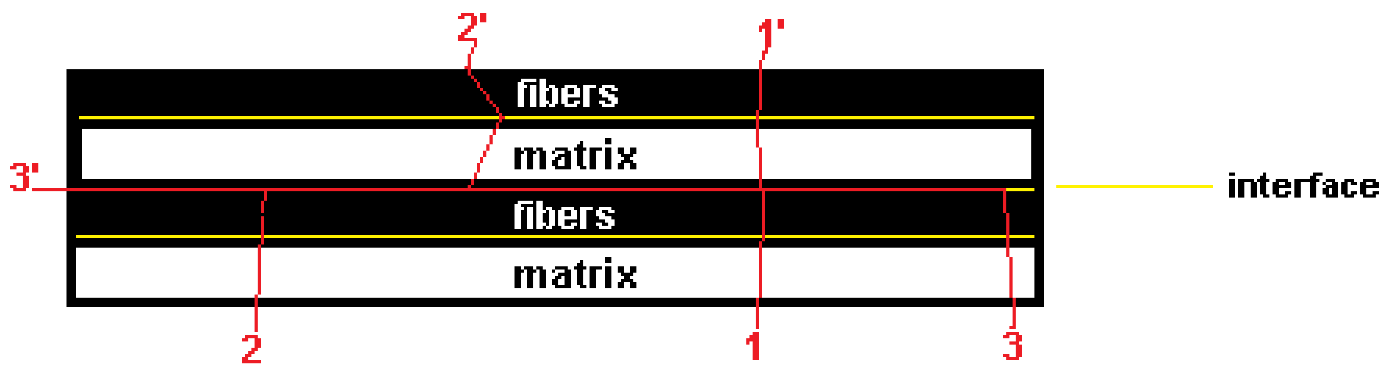
Figure 2.
(2a) intact specimens and (2b) aged specimens used in Charpy tests [27].
Figure 2.
(2a) intact specimens and (2b) aged specimens used in Charpy tests [27].
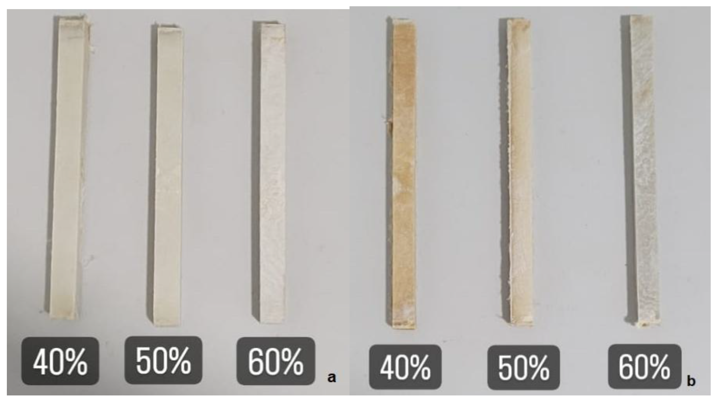
Figure 3.
Sketch of a Charpy test specimen with relevant regions in red.
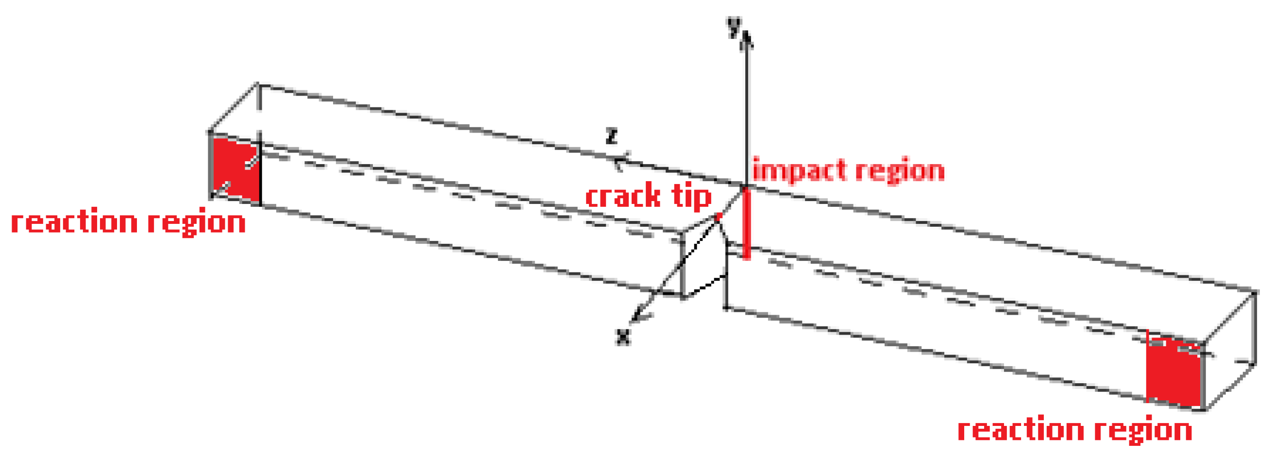
Figure 4.
Propagation of tensile stress field due to the impact load during the Charpy test.
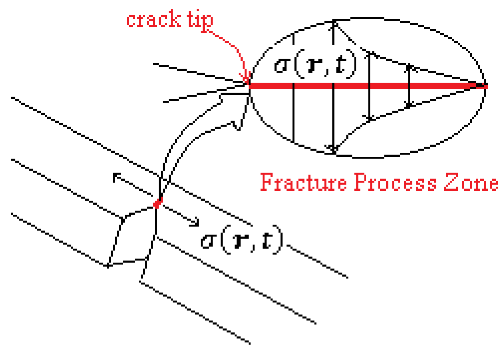
Figure 5.
The infinitesimal displacement vector during a continuous deformation.
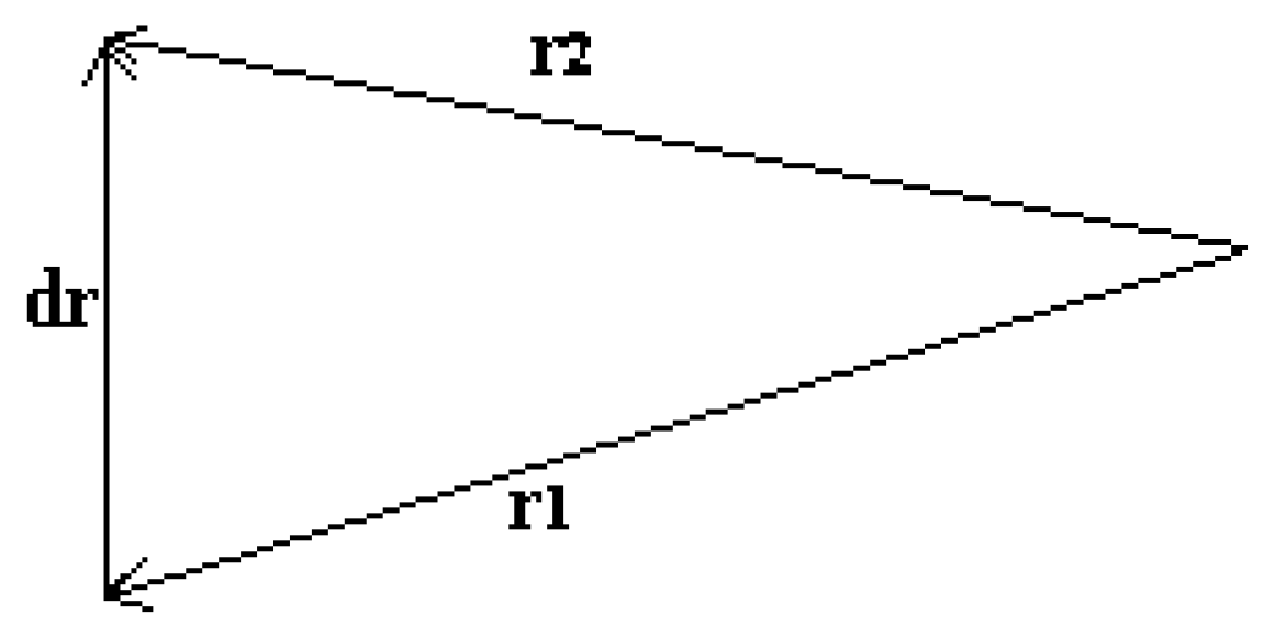
Figure 6.
Means of impact strength vs fiber volume fractions for the intact specimens.
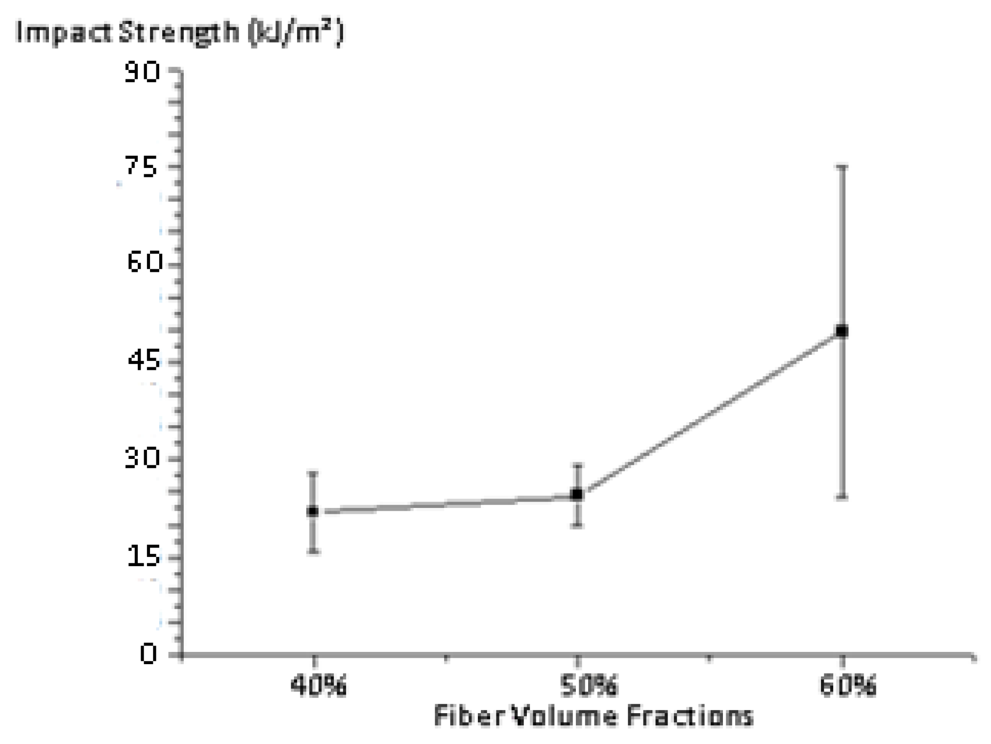
Figure 7.
Some fracture surface profiles of intact specimens with 60% of theoretical volume fraction. .
Figure 7.
Some fracture surface profiles of intact specimens with 60% of theoretical volume fraction. .
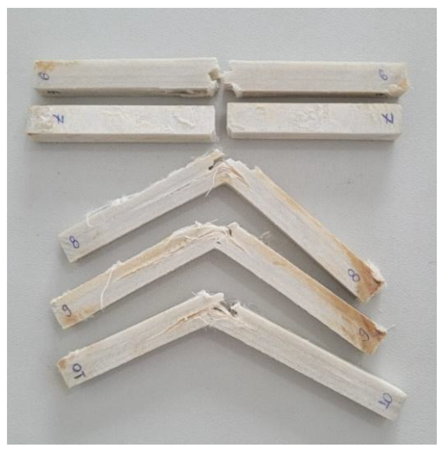
Figure 8.
Means of impact strength vs fiber volume fractions for the C-UV aged specimens.
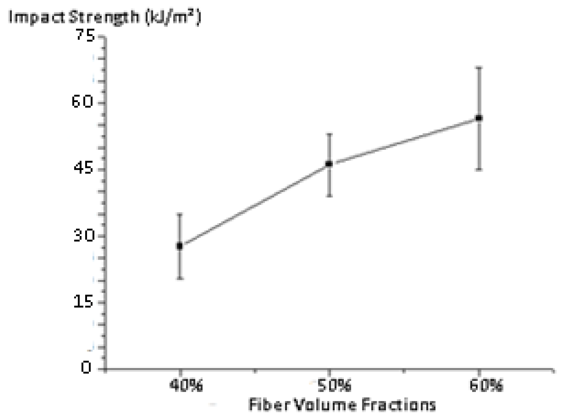
Figure 9.
Some fracture profiles in intact specimens. (9A) 40%, (9B) 50% and (9C) 60% fiber theoretical volume fraction.
Figure 9.
Some fracture profiles in intact specimens. (9A) 40%, (9B) 50% and (9C) 60% fiber theoretical volume fraction.
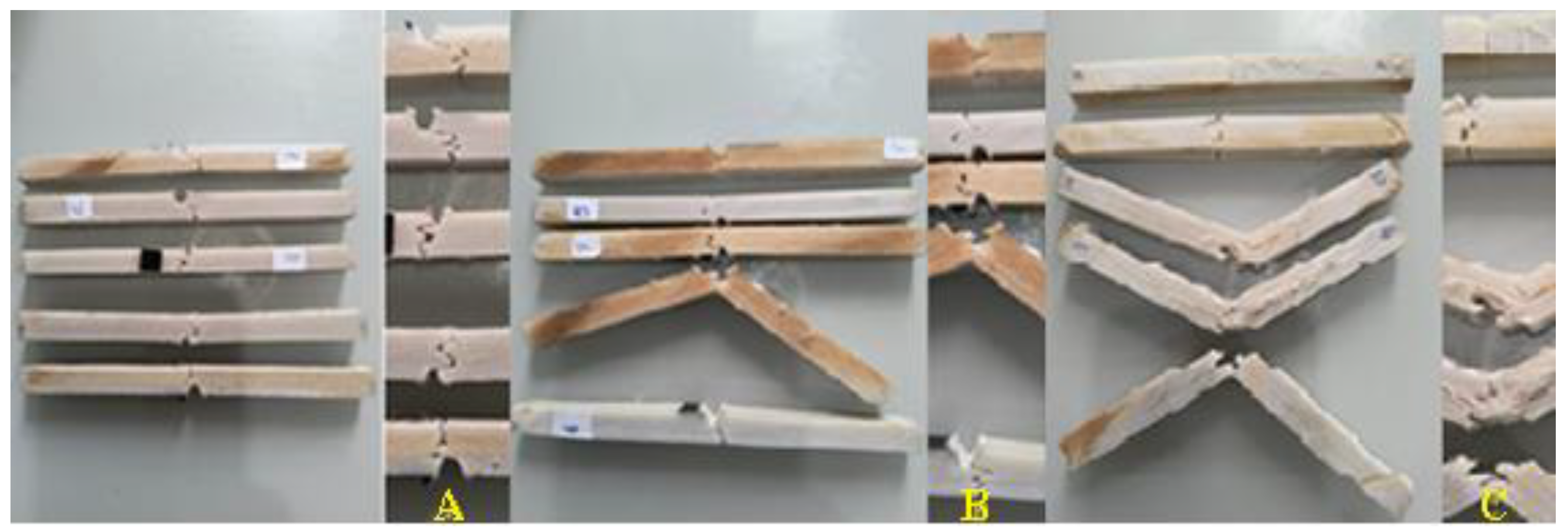
Figure 10.
Characterization of a fracture surface region with only intralaminar damage and the respective magnifications: 45x (10a), 120x (10b), 300x (10c) and 700x (10d).
Figure 10.
Characterization of a fracture surface region with only intralaminar damage and the respective magnifications: 45x (10a), 120x (10b), 300x (10c) and 700x (10d).
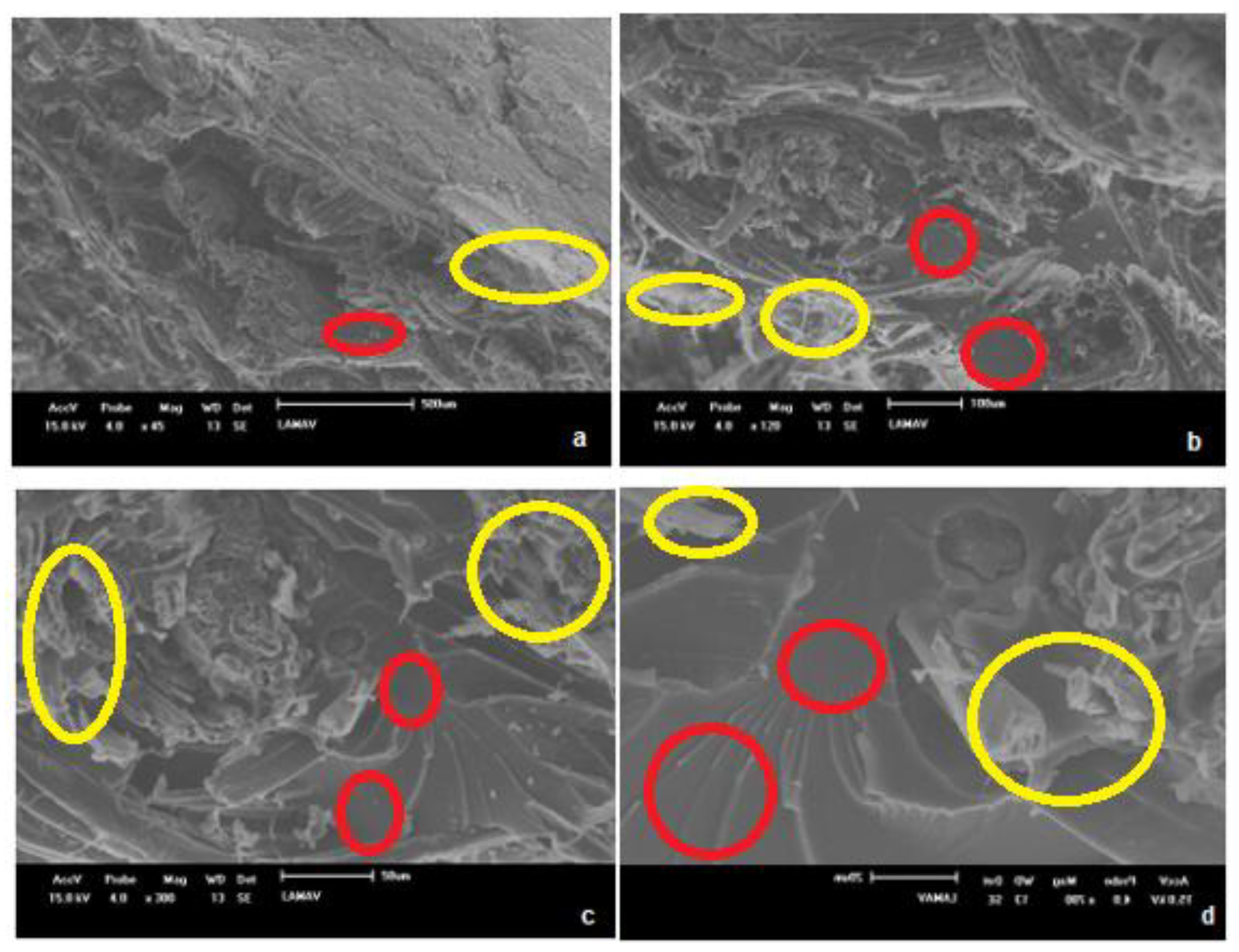
Figure 11.
Interlaminar fracture region with weak adhesion for the interface and the respective magnifications: 20x (11a), 36x (11b), 100x (11c) and 300x (11d).
Figure 11.
Interlaminar fracture region with weak adhesion for the interface and the respective magnifications: 20x (11a), 36x (11b), 100x (11c) and 300x (11d).
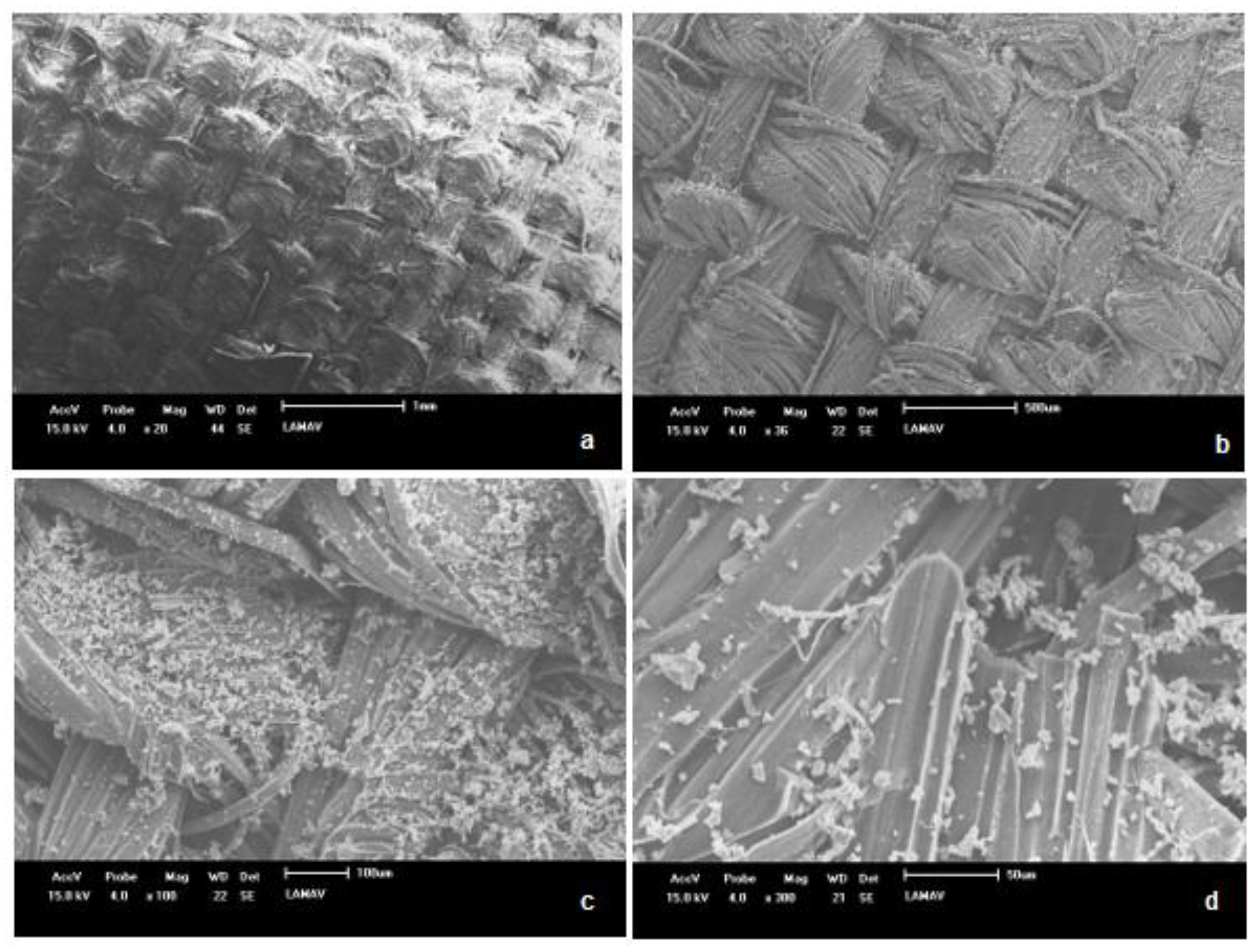
Figure 12.
Some fracture profiles of C-UV aged specimens with moderate interface quality. (12A) 40%, (12B) 50% and (12C) 60% fiber theoretical volume fraction.
Figure 12.
Some fracture profiles of C-UV aged specimens with moderate interface quality. (12A) 40%, (12B) 50% and (12C) 60% fiber theoretical volume fraction.
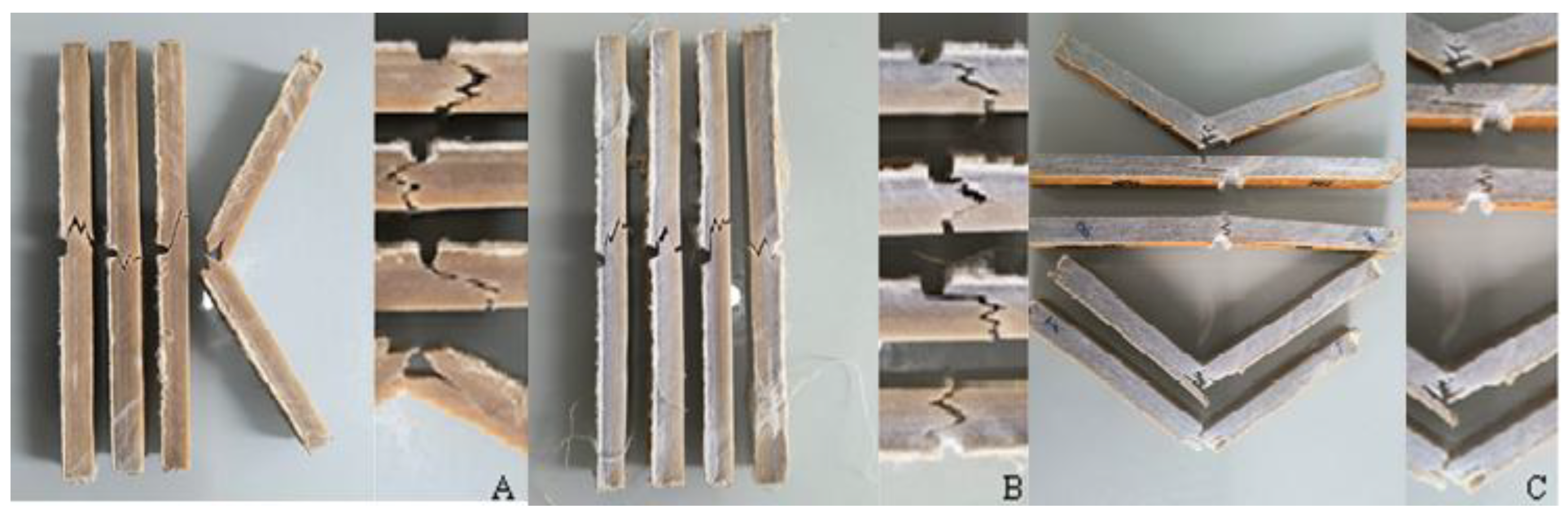

Table 1.
Fiber theoretical volume fractions used and the respective number of ramie woven fabric plies.
Table 1.
Fiber theoretical volume fractions used and the respective number of ramie woven fabric plies.
| Fiber theoretical volume fraction | 40% | 50% | 60% |
| Number of plies | 70 | 87 | 105 |
Table 2.
Means and standard deviations of Charpy tests using intact specimens with 40%, 50% and 60% of fiber theoretical volume fractions.
Table 2.
Means and standard deviations of Charpy tests using intact specimens with 40%, 50% and 60% of fiber theoretical volume fractions.
| %Volfiber | Energy (J) | Notch Toughness (J/m) | Impact Strength (kJ/m²) |
| 40% | 1,28 0,35 | 139,91 37,67 | 21,83 6,08 |
| 50% | 1,48 0,36 | 158,53 36,10 | 24,45 4,59 |
| 60% | 3,86 1,87 | 414,09 200,24 | 49,67 25,44 |
Table 4.
Means and standard deviation of Charpy tests using C-UV aged specimens with 40%, 50% and 60% of fiber theoretical volume fractions.
Table 4.
Means and standard deviation of Charpy tests using C-UV aged specimens with 40%, 50% and 60% of fiber theoretical volume fractions.
| %Volfiber | Energy (J) | Notch Toughness (J/m) | Impact Strength (kJ/m²) |
| 40% | 2,31 0,77 | 231,11 76,60 | 27,62 7,25 |
| 50% | 3,54 0,61 | 354,40 61,12 | 46,11 6,59 |
| 60% | 4,55 1,18 | 455,00118,22 | 56,47 11,55 |
Table 5.
The p-values of Dunn’s post hoc test for the impact strength data of all groups.
| 40% intact | 50% intact | 60% intact | 40% aged | 50% aged | 60% aged | |
| 40% intact | 0,4621 | 0,0003139 | 0,1971 | 9,552.10-5 | 1,398.10-6 | |
| 50% intact | 0,4621 | 0,004672 | 0,5603 | 0,001661 | 5,1.10-5 | |
| 60% intact | 0,0003139 | 0,004672 | 0,03398 | 0,6992 | 0,2031 | |
| 40% aged | 0,1971 | 0,5603 | 0,03398 | 0,001455 | 0,0009424 | |
| 50% aged | 9,522.10-5 | 0,001661 | 0,6992 | 0,01455 | 0,3876 | |
| 60% aged | 1,398.10-6 | 5,1.10-5 | 0,2031 | 0,0009424 | 0,3876 |
Disclaimer/Publisher’s Note: The statements, opinions and data contained in all publications are solely those of the individual author(s) and contributor(s) and not of MDPI and/or the editor(s). MDPI and/or the editor(s) disclaim responsibility for any injury to people or property resulting from any ideas, methods, instructions or products referred to in the content. |
© 2025 by the authors. Licensee MDPI, Basel, Switzerland. This article is an open access article distributed under the terms and conditions of the Creative Commons Attribution (CC BY) license (http://creativecommons.org/licenses/by/4.0/).
Copyright: This open access article is published under a Creative Commons CC BY 4.0 license, which permit the free download, distribution, and reuse, provided that the author and preprint are cited in any reuse.


