Submitted:
19 June 2025
Posted:
20 June 2025
You are already at the latest version
Abstract
Localization of Unmanned Aerial Vehicles (UAVs) in spaces with a limited availability of Global Navigation Satellite System (GNSS) signals presents a challenge, and one possible solution is the usage of Ultra-Wideband (UWB) transceivers as an aid in the localization process. This paper examines the influence of placing the UWB anchors on the UAVs' localization accuracy in indoor spaces. Different testing scenarios, with variations in the number of anchors and their relative position towards the UAV, were created. Results show that the anchor placement plays an important role and is a significant factor in achieving accurate positioning of UAVs. The error for different testing configurations was shown through the RMSE for each axis, backed up by the standard deviation. The increase in the number of UWB anchors with the combined use of an additional laser ranging sensor for altitude measurement provided the best result, and the RMSE was less than 19 cm in each axis of a 3D coordinate system with the standard deviation of up to 3 cm. For the testing scenarios that included the usage of a laser altimeter, the RMSE for the z-axis dropped below 1 cm, with the standard deviation under 3 mm.
Keywords:
UAV
; UWB
; localization
; anchor
; time of arrival
; two-way ranging
; laser altimeter
1. Introduction
The recent development and maturing of the Unmanned Aerial Vehicle (UAV) technology opened different fields of research related to their navigation, both in outdoor and indoor environments. Depending on the actual use cases and requirements, UAVs are equipped with various navigation systems, providing them with capabilities of global and local positioning. In the outdoor environments, with the moderate requested accuracy, usage of the Global Navigation Satellite Systems (GNSS) proves sufficient, with the expected accuracy of up to a couple of meters. The recent development of imaging devices, including visible light (RGB) and multispectral cameras and LiDARs, paved the way for the usage of rather cheap equipment for photogrammetric tasks [1]. The standard precision positioning GNSS signal is not sufficiently accurate for most of the tasks UAVs are meant to perform [2], and the Real-Time Kinematic (RTK) is usually the solution for achieving the centimeter-level positioning accuracy [3]. RTK proves to be accurate enough for mapping of objects and terrain or agricultural usage, but it requires a base station or access to a GNSS reference station in real-time. Even though this setup is rather easy to achieve, it is not an ad-hoc solution, and the usable results are possible only in outdoor environments. Knowing the exact position is necessary in single- or multi-UAV systems, but the relative position in multi-UAV systems is not guaranteed with the usage of satellite-based positioning alone. To cope with the operation of autonomous swarms and for indoor navigation of individual UAVs, or swarms of UAVs, is the main reason why the relative localization is being investigated by many researchers [4]. Among the relative localization methods, the Ultra-Wideband (UWB) localization technology provides a solution to achieve a centimeter- (or decimeter) level accuracy, which should enable the usage of UAVs in indoor environments and provide the additional capability to improve the relative localization of individual UAVs in swarms outdoors. UWB is basically a wireless communication technology operating in a wide frequency spectrum, from 3.1 GHz to 10.6 GHz [5]. It is used to transmit and receive signals between the UAV and the pre-built infrastructure or between two or more UAVs. UWB technology relies on the usage of extremely short pulses, typically in the order of nanoseconds, requiring a wide frequency range. There are two typical approaches in UWB-based localization: the time of flight (ToF) and the time difference of arrival (TDoA). These approaches are sometimes backed up by the angle of arrival (AoA), which can help in reducing the error by using the information about the angle from which the signal arrives. Besides the unavailability of the GNSS signal in indoor environments, the structure of the space, and the material from which it is built, play an important role, because they can lead to undesired effects of multipath signal propagation, where unwanted reflections from walls and objects lead to incorrect measurements on which the localization accuracy relies [6,7]. In this paper, we will show the results of the influence of the surroundings and relative position between the UWB anchors and a UAV in different configurations and provide guidelines for choosing the optimal setup regarding the potential use case. The real-world usage of a system is usually somewhat compromised by the possibilities to place the localization equipment at optimal places, and those compromises could lead to an increase in the dilution of precision (DOP), which we will show through intentionally falsely chosen locations of anchors. Depending on the possibility of placing the anchors, and because a UAV can move in three dimensions, the vertical component may have a larger error, especially when anchors are in the same horizontal plane. To overcome that problem, we will provide a possible solution by introducing augmentation using an additional laser-based altitude sensor and compare the localization accuracy with and without it.
The rest of the paper is structured as follows: Section 2 brings a brief literature overview covering the research activities in the field of UWB-based localization. Section 3 provides a description of the equipment used, its limitations, and achievable accuracy. Section 4 describes the methodology and shows the experimental setup used throughout the experiments. Section 5 shows the results of measurements and provides a discussion about the achievements through different configurations of anchors and their relative positions towards the UAV. Finally, section 6 brings conclusive remarks and guidelines for future work.
2. The Recent Research in the UWB-Based Localization
The UWB-based localization, especially in indoor environments, has been considered in many studies in recent years. Although it is a well-known principle, there are many directions in which researchers have pointed their attention. One of the biggest challenges of the UWB technology used in positioning is the influence of the mutual position between the fixed points (anchors) and targets, which usually move, either on the ground or fly in 3 dimensions. Cho et al. [8] were trying to determine the optimal location of UWB tags on a construction site to obtain the best localization accuracy of a mobile terminal. The mobile terminal could measure the actual distance between each tag, and to determine its location, the author used trilateration, which was proprietary developed. Depending on the location of tags, the value of positional DOP (PDOP) varied from 1.50 to 3.39, and even to infinity, in the case of coplanar location of tags, which increased the vertical DOP so much that the system could not provide 3D position accurately. They achieved an accuracy of around 35 cm in 3D positioning, using the proposed method. Monica and Ferrari [9] were trying to locate the target in an industrial environment with automated ground vehicles using the TDoA-based method. In their simulation, the vehicle was able to move only on the ground, which reduced the complexity of the network of anchors, and the favorable location was chosen to be above the ground vehicle on the ceiling with as large as possible angle between the anchors and the vehicle, which significantly reduced the vertical DOP. Besides the open spaces, where the line of sight (LoS) is present, many use-cases include non-LoS environments (NLoS), where there is a complete or partial occlusion between the anchors and the target. These scenarios were investigated by Pan et al. [10] and Albaidhani et al. [11]. In both cases, the localization accuracy was significantly lower and not acceptable for the precise usage of UAVs indoors. To improve the 3D accuracy, Pan et al. [12] proposed coplanar placement of UWB anchors and proved that the overall error is significantly reduced with the optimal placement of UWB anchors. Cerro et al. [13] compared the performance of different available hardware for UWB-based positioning: Decawave, BeSpoon, and Ubisense. The tests were carried out for different numbers and positions of anchors, and in static and dynamic conditions. The authors set the error threshold to be 60 cm and provided a comparison of the device’s performance for 4 to 12 anchors in two configurations. Their results show that the Decawave hardware provides a slightly better and more consistent performance, which corresponds well to the results Ruiz and Granja [14]. The obtainable error was within 60 cm for 9 or more anchors and for all of the tested equipment. Ferrigno et al. [15] also dealt with the anchor placement and robustness of the UWB-based localization using the Decawave hardware and, through the experiment, obtained errors from 22 cm to 72 cm. It is important to note that the authors used only three anchors, which somewhat reduced the localization accuracy of the system. During the last decade, many papers dealing with the usage of UWB for localization purposes in industrial environments were published [16,17,18,19,20,21,22], marking this technology highly interesting for automation and motion control.
Autonomous landing is one of the special cases that includes the usage of the UWB technology, where Nguyen et al. [23] used the UWB technology to aid visual-based docking in the approach phase, which lasts until the visual sensors recognize the markers on the landing pad. Miranda et al. [24] combined the usage of the UWB technology, IMU, and GPS in landing a delivery UAV in a designated area.
Operating swarms of UAVs is rather challenging if the relative localization is performed through the exchange of relative distances between individual UAVs. Guo et al. [25] proposed a relative localization achieved through a distance-based method for UAV swarm formation control and successfully managed to maintain the equilateral triangle formation in a leader–follower technique, in which the leader UAV is manually controlled and moves freely, while other UAVs are following it. The mentioned before, AoA is not something that can be estimated from the UWB signal and requires the use of a direction sensing antenna, which has completely different properties from the antennas on UWB tags. The approach utilizing an antenna array for measuring both the distance and the angle between two UAVs was presented by Gu et al. [26]. The authors reported the accuracy of around 23 cm at a speed of 0.64 m/s.
Simultaneous localization and mapping (SLAM) is another research field where the UWB localization technology is used. One of the studies dealing with the choice of the correct equipment for the SLAM is from Gerwen et al. [27]. They analyzed which sensors are the best suited to which UAVs, respectively to their size, and compared the accuracy obtained by using a different number of anchors. An interesting outcome of this study is the comparison of accuracy after aiding the UWB localization technology with a sonar. The authors obtained an average positioning error of 67 cm in 3D, and after adding an inexpensive altitude sonar, the average error dropped to 10.71 cm. Although this reduction in the positioning error is significant, it is still rather high for many use cases. A movable localization system relying on UWB, an attitude and heading reference system, and a barometer for altitude augmentation was proposed by Moon and Yoon [28], where they have shown how the sole usage of a UWB-based localization system is not sufficient on its own. As mentioned before, the accurate estimation of altitude (z-axis) is usually a more difficult task due to the geometry of the anchors in the majority of indoor localization methods, and one of the approaches is to include additional information provided by different sensors, as did Si et al. [29] and Yang et al. [30] with the combination of a barometer and UWB, similar to the work of Zhang et al. [31] for swarms of UAVs.
3. The UWB Equipment Used in Experiments
To test the various scenarios of placement of UWB anchors and influence on the localization accuracy of the UAV, we have used the ecosystem from Bitcraze AB, Malmö, Sweden, consisting of the UAV (Crazyflie) equipped with STM32F405 microcontroller unit (MCU) and nRF51822 radio and power management MCU, as shown in Figure 1.
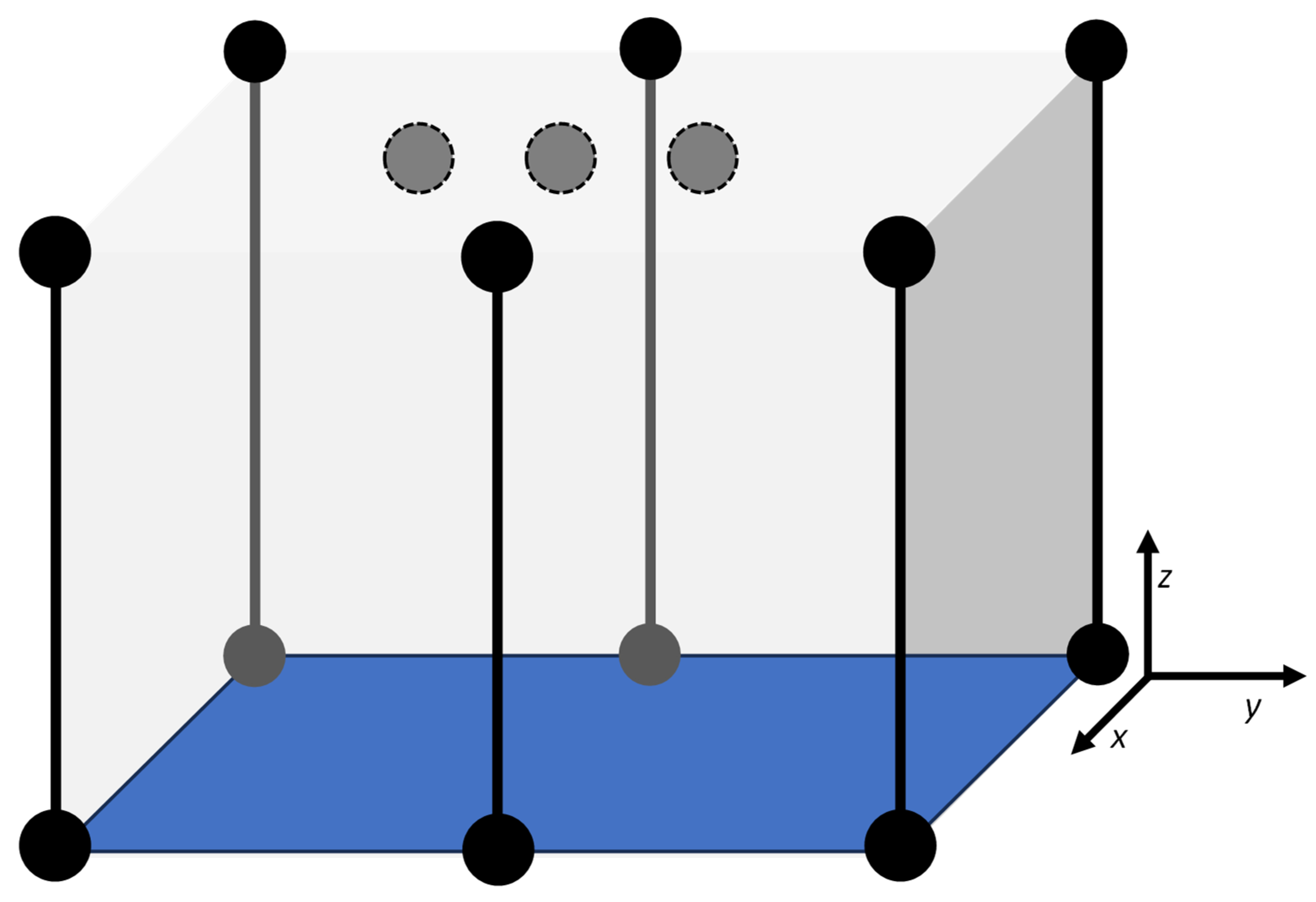
The UWB hardware is slightly different in the case of the rover (Loco Positioning expansion deck) and the anchor (Loco Positioning node), as shown in Figure 2 (a) and (b), respectively.
In terms of UWB transceivers, both devices use the same Decawave DWM1000 module compatible with the IEEE 802.15.4 UWB specification. The operating bandwidth is from 3.2 GHz to 7 GHz with a channel bandwidth of 500 MHz. The ranging rate is 500 Hz, which is distributed among the number of anchors used in each setup. This means that the ranging rate per anchor can be calculated using the following expression:
where Rfa is the ranging frequency per anchor, Rf is the achievable ranging frequency of the expansion deck, and Na is the number of used anchors. The anchors are built around the STM32F072 MCU, and the configuration can work with up to 8 anchors simultaneously. It needs to be noted that it is required to have 4 or more anchors to achieve good 3D-localization, meaning that variation in the number of anchors using this hardware is rather limited. Both devices can achieve a ranging accuracy of around ±10 cm, which corresponds to the performance of the DWM1000 module. Height estimation proves to be more challenging than horizontal positioning, and for that reason, we decided to use an additional sensor to estimate the height of the UAV from the floor and merge its readings with the UWB-based localization. The used sensor is based on the VL53L1x ToF sensor, capable of measuring distances up to 4 meters with an average error within a few millimeters.
4. Methodology and the Experimental Setup
In the previous section, we mentioned that 3D positioning requires at least 4 anchors, and the maximum supported number of anchors is 8. This research aims to create guidelines for the placement of anchors to achieve maximum positioning accuracy and observe the influence of indoor environments. Indoor spaces are often height-limited, so we will place anchors and allow movement of the UAV inside and in proximity of the volume defined by the anchor positions. In actual applications, the anchor positions are usually in the bottom corners of the room where positioning takes place, and some authors suggested placement of anchors above the UAV, in the center of the room, or the top corners. These approaches make sense in terms of reducing the DOP factor, which influences the final poisoning accuracy and is defined by:
where Δ is the final positioning error in meters, PDOP is positional dilution of precision consists of the horizontal and vertical dilution of precision, and δR is the error in ranging caused by the sensor. Placing the target inside the volume defined by the position of the anchors will reduce the (P)DOP, as shown in [32].
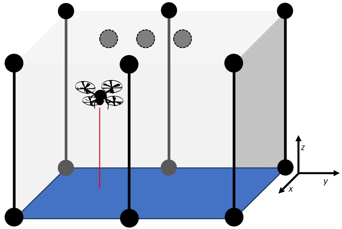
Figure 3.
The volume inside which the localization accuracy was measured with the used coordinate system. Circles represent UWB anchors, gray dashed circles show possible locations of overhead UWB anchors, and vertical lines represent columns along which UWB anchors can change their altitude.
Figure 3.
The volume inside which the localization accuracy was measured with the used coordinate system. Circles represent UWB anchors, gray dashed circles show possible locations of overhead UWB anchors, and vertical lines represent columns along which UWB anchors can change their altitude.
We aimed to evaluate the accuracy and stability of UWB-based localization in an indoor environment for a static UAV using different anchor configurations, with 4 to 6 anchors used simultaneously. The UAV was placed at a fixed position in space so that its position is static and always known. The main objective was to analyze how anchor geometry and sensor fusion, specifically the inclusion of a laser altimeter, influence the positional accuracy along the x, y, and z axes. Key performance indicators include Root Mean Square Error (RMSE), standard deviation (STDEV), and average position (AVG) in each axis. The RMSE was calculated as:
where N is the number of measurements, di is the x or y component of i-th measurement, and d is the actual position of the UAV. The standard deviation was calculated using:
where is the average (AVG) of the measurements.
The UWB localization method used in the experiment is based on ToF measurements between a tag (attached to the UAV) and multiple fixed anchors. The position of the tag is calculated using trilateration, a mathematical method that finds a point in space based on its distances from known reference points, which can be written as:
where (xi, yi, zi) are coordinates of the i-th anchor in Euclidean space, (x, y, z) are coordinates of the tag (unknown), di is the distance between each anchor and the tag, and n is the number of anchors, which varies from 4 to 6 in our case. Solving this system requires at least four non-coplanar anchors if there is no additional information of the dimension perpendicular to the plane defined by the anchors. Using more anchors improves redundancy and mitigates errors caused by signal noise, non-line-of-sight (NLoS) conditions, or poor geometry (high DOP factor). To evaluate how the spatial distribution of anchors affects UWB localization accuracy, four unique configurations were tested. Each configuration increased the spatial diversity and number of anchors progressively, allowing a structured comparison of their impact on position estimation. Table 1 presents the details of the configurations used in experiments, while the configurations used (1-4) are shown in Figure 4 (a)-(d), respectively.
The UAV was hanging from the support mounted on a wooden pole using a non-elastic thread, ensuring a fixed and stable position in 3D space throughout all measurements. This eliminated dynamic motion effects and allowed for the evaluation of system accuracy in a controlled and repeatable environment. The known static position of the UAV served as the reference for performance evaluation. Four distinct anchor configurations were designed to progressively increase the geometric diversity and redundancy of the localization system. Each configuration was tested under the same environmental conditions to ensure comparability, and additionally, each configuration was tested with and without the inclusion of the laser-based altimeter. The altimeter was integrated to provide altitude correction and improve z-axis stability, especially important in coplanar or nearly coplanar anchor setups.
5. Measurement Results and Discussion
The objective of the experiments was to evaluate the accuracy and performance of the UAV's position estimation in different UWB anchor configurations and to observe the influence of a relative distance to different anchors on the accuracy of position estimation. The measurements were performed at three fixed positions in the xy-plane and at three different heights.
5.1. Measurement Results
A total of four UWB anchor configurations were tested to evaluate their effect on positioning accuracy. Each configuration was tested under the same conditions in a 3×4×2-meter indoor space, as described in the previous section. Figure 5. shows the positions at which the UAV was fixed to perform measurements. Each pair of (x, y) coordinates was measured at three different heights, and each point was averaged over 500 samples with and without the ToF-based laser height sensor.
To evaluate the overall accuracy, the RMSE and the STDEV in the x and y axes were calculated for each configuration, with results aggregated across all three test points and all height levels. Table 2 presents the average results and serves to provide the expected error in positioning inside a similarly sized volume.
Another important factor that significantly influences the final achieved accuracy of any localization system is the PDOP. Depending on the measured unit and nature of the system meant to provide accurate position, it can be expected that the PDOP is usually smaller towards the center of the volume stretched by anchors of a non-autonomous localization system. Table 3. presents calculated PDOPs for the Configuration 1, where P1 corresponds to the location of (0.75, 1.0) m, P2 corresponds to the location of (1.5, 2.0) m, and P3 corresponds to the location of (3.0, 3.0) m, H1 corresponds to the height of 0.5 m, H2 corresponds to the height of 1.0 m, and H3 corresponds to the height of 1.5 m.
Depending on the chosen x and y coordinates, Figure 6 (a), (b), and (c) show 3D scatter plots of estimated UAV locations using four anchor configurations and present the influence of configuration and PDOP on the expected accuracy of localization.
The UWB-based localization struggles in Configuration 1, where anchors are placed coplanarly, but shows a sufficient accuracy in other configurations. However, adding a lightweight and inexpensive laser height sensor eliminated the z-axis error completely. Across all configurations, the RMSE of x and y ranged between 0.13 m and 0.19 m, with configuration 4 offering the most accurate and consistent results. From Table 3, it is obvious that choosing a coplanar anchor setup leads to large values of PDOP, where everything above 2, and especially 10 or even more, is unacceptable and leads to significant positioning errors.
5.2. Discussion
During the measurements and through the results of measurements, shown in the previous subsection, we observed a consistent spatial bias, likely related to the anchor placement geometry or a potential miscalibration of the system. This is somewhat expected in every real-world application, because it is rather difficult to set up an anchor system without any absolute positional error, and there is a question whether that is always necessary, since the UWB-based localization relies on the relative distance between transceivers. Estimated positions tend to cluster in a tight cloud with a small offset from the real location of the UAV, as shown in Figure 6. This bias appears to be stable across all tested configurations, implying it is a systematic bias rather than a random one. Because the bias is repeatable, it may be possible to correct it through simple calibration or error modelling and provide even more accurate position estimation. A developed system with a similar architecture could benefit more from an initial bias compensation than from optimizing anchor configurations, if configuration 1 is to be taken out of consideration, because of its lack of variation in the z-axis. Even though the indoor space was controlled and cleared of almost all metallic objects, it inevitably introduced multipath reflections. This has likely contributed to some noise in the position estimates, which further increased the RMSE.
Diversity in height of anchors from the ground plane (floor), generally, provides better results, especially in the z-axis, where only horizontally and coplanarly placed anchors produce unacceptably large errors, and, sometimes, even physically impossible results. To mitigate the problem of the height (z-axis) estimation, a good practice is to use an additional sensor, and to backup that we used a laser-based ToF altimeter that works very well in indoor environments, but would not work well in outdoor environments, especially during the day, because of the interference caused by the sunlight. The height sensor successfully reduced the z-axis error with the RMSE z lower than 1 cm, while the error in the xy-plane stayed similar.
The PDOP values vary across different anchor configurations and test positions, indicating how geometry affects positioning accuracy, but follow the rule of a smaller expected PDOP value close to the center of the volume. Configuration 1 consistently shows the highest PDOP across all positions, suggesting a poor geometric diversity in anchor placement for this setup. Configuration 4 provides more consistent and usually the lowest PDOP values. It can be observed that across all tested configurations, increasing the height of the UAV’s position reduces PDOP, indicating that a larger 3D spatial separation between anchors and the UAV improves geometry and, consequently, reduces the PDOP. Configurations 2 and 3 produce stable and relatively low PDOP values for all test points. They show a better consistency across varying heights compared to Configuration 1, but with a larger deviation than Configuration 4, especially in some positions close to the edge of the volume stretched by the anchors. These observations suggest that careful 3D placement of anchors will significantly lower the PDOP, thus improving localization accuracy. Configuration 4 stands out as the most geometrically efficient setup among the four and can be taken as a starting point in planning a UWB anchor setup.
Usage of the additional height sensor successfully reduced the z-axis error, while the error in the xy-plane stayed similar, and it is highly advisable to use an appropriate height sensor depending on the usage conditions and requirements.
5. Conclusions
In this paper, we studied how the position of anchors influences the localization accuracy of UWB-based positioning. The total of four configurations with 4 to 6 UWB transceivers was used, and all the measurements were made with and without the use of a laser-based ToF altimeter to provide better results for the altitude estimation. The measurement results proved that the anchor setup is very important, and depending on the use case and the space that needs to be covered by the localization systems, the position of anchors needs to offer as much spatial diversity as possible to overcome a poor PDOP. Achieving a good PDOP is mostly the result of a good spatial distribution of anchors, and if the positions are chosen correctly, the expected values of the PDOP are below 1.5. Mostly because of the nature of the space where the UWB-based localization is intended, the altitude estimation usually suffers, because the xy-plane anchors are better stretched, and the overhead anchor at a high altitude is sometimes impossible to place. To overcome that potential problem, it is advised to use an independent source of information in the form of a laser- or ultrasound-based altitude sensor. Generally, currently available UWB-positioning technology can provide a positioning accuracy of 10 cm in all axes of a 3D coordinate system, stretching the uncertainty volume at around 1 dm3, which might not be suitable for high-precision applications. Further introduction of reflexive surfaces that introduce multi-path propagation would further decrease the expected accuracy. The future work in this field will be towards space and noise modelling to overcome reflection-based errors, and experimenting with navigation in complex spaces with a larger number of anchors.
Author Contributions
Conceptualization, L.K. and M.M.; methodology, M.M. and T.R.; measurements, L.K. and M.M.; validation, M.M. and T.R.; resources, M.M. and T.R.; writing—original draft preparation, M.M. and L.K.; writing—review and editing, T.R.; visualization, M.M.; supervision, T.R.; project administration, T.R.; funding acquisition, T.R. and M.M. All authors have read and agreed to the published version of the manuscript.
Funding
This research was funded by the Horizon Europe CSA project, “Strengthening Research and Innovation Excellence in Autonomous Aerial Systems—AeroSTREAM”, call HORIZON-WIDERA-2021-ACCESS-05, grant agreement number 101071270.
Acknowledgments
This research was conducted within a Horizon Europe CSA project, “Strengthening Research and Innovation Excellence in Autonomous Aerial Systems—AeroSTREAM”, call HORIZON-WIDERA-2021-ACCESS-05, grant agreement number 101071270.”
Conflicts of Interest
The authors declare no conflicts of interest.
Abbreviations
The following abbreviations are used in this manuscript:
| AoA | Angle of Arrival |
| GNSS | Global Navigation Satellite System(s) |
| LoS | Line of Sight |
| PDOP | Positional Dilution of Precision |
| RGB | Red, Green, Blue (representing the primary colors of the visible spectrum) |
| RMSE | Root Mean Squared Error |
| RTK | Real-Time Kinematic |
| STDEV | Standard deviation |
| TDoA | Time Difference of Arrival |
| ToF | Time of Flight |
| UAV | Unmanned Aerial Vehicle |
| UWB | Ultra-Wideband |
References
- Elkhrachy, I. Accuracy Assessment of Low-Cost Unmanned Aerial Vehicle (UAV) Photogrammetry. Alexandria Engineering Journal 2021, 60, 5579–5590. [Google Scholar] [CrossRef]
- Li, X.; Ge, M.; Dai, X.; Ren, X.; Fritsche, M.; Wickert, J.; Schuh, H. Accuracy and Reliability of Multi-GNSS Real-Time Precise Positioning: GPS, GLONASS, BeiDou, and Galileo. J Geod 2015, 89, 607–635. [Google Scholar] [CrossRef]
- Kim, H.; Hyun, C.-U.; Park, H.-D.; Cha, J. Image Mapping Accuracy Evaluation Using UAV with Standalone, Differential (RTK), and PPP GNSS Positioning Techniques in an Abandoned Mine Site. Sensors 2023, 23, 5858. [Google Scholar] [CrossRef] [PubMed]
- Kramarić, L.; Jelušić, N.; Radišić, T.; Muštra, M. A Comprehensive Survey on Short-Distance Localization of UAVs. Drones 2025, 9, 188. [Google Scholar] [CrossRef]
- Oppermann, I.; Hämäläinen, M.; Iinatti, J. UWB: Theory and Applications; John Wiley & Sons: Hoboken, NJ, USA, 2004; ISBN 978-0-470-86917-8. [Google Scholar]
- Foerster, J.R. The Effects of Multipath Interference on the Performance of UWB Systems in an Indoor Wireless Channel. In Proceedings of the IEEE VTS 53rd Vehicular Technology Conference, Spring 2001. Proceedings (Cat. No.01CH37202); IEEE: Rhodes, Greece, 2001; Volume 2, pp. 1176–1180. [Google Scholar]
- Lee, J.-Y.; Scholtz, R.A. Ranging in a Dense Multipath Environment Using an UWB Radio Link. IEEE J. Select. Areas Commun. 2002, 20, 1677–1683. [Google Scholar] [CrossRef]
- Cho, J.; Jeong, S.; Lee, B. A Study on Anchor Placement and 3D Positioning Algorithm for UWB Application in Small Sites. KSCE Journal of Civil Engineering 2024, 28, 4575–4587. [Google Scholar] [CrossRef]
- Monica, S.; Ferrari, G. UWB-Based Localization in Large Indoor Scenarios: Optimized Placement of Anchor Nodes. IEEE Trans. Aerosp. Electron. Syst. 2015, 51, 987–999. [Google Scholar] [CrossRef]
- Pan, H.; Qi, X.; Liu, M.; Liu, L. Map-Aided and UWB-Based Anchor Placement Method in Indoor Localization. Neural Comput & Applic 2021, 33, 11845–11859. [Google Scholar] [CrossRef]
- Albaidhani, A.; Morell, A.; Vicario, J.L. Anchor Selection for UWB Indoor Positioning. Trans Emerging Tel Tech 2019, 30, e3598. [Google Scholar] [CrossRef]
- Pan, H.; Qi, X.; Liu, M.; Liu, L. An UWB-Based Indoor Coplanar Localization and Anchor Placement Optimization Method. Neural Comput & Applic 2022, 34, 16845–16860. [Google Scholar] [CrossRef]
- Cerro, G.; Ferrigno, L.; Laracca, M.; Miele, G.; Milano, F.; Pingerna, V. UWB-Based Indoor Localization: How to Optimally Design the Operating Setup? IEEE Trans. Instrum. Meas. 2022, 71, 1–12. [Google Scholar] [CrossRef]
- Jimenez Ruiz, A.R.; Seco Granja, F. Comparing Ubisense, BeSpoon, and DecaWave UWB Location Systems: Indoor Performance Analysis. IEEE Trans. Instrum. Meas. 2017, 66, 2106–2117. [Google Scholar] [CrossRef]
- Ferrigno, L.; Miele, G.; Milano, F.; Pingerna, V.; Cerro, G.; Laracca, M. A UWB-Based Localization System: Analysis of the Effect of Anchor Positions and Robustness Enhancement in Indoor Environments. In Proceedings of the 2021 IEEE International Instrumentation and Measurement Technology Conference (I2MTC), Glasgow, United Kingdom, 17 May 2021; IEEE; pp. 1–6. [Google Scholar]
- Silva, B.; Pang, Z.; Akerberg, J.; Neander, J.; Hancke, G. Experimental Study of UWB-Based High Precision Localization for Industrial Applications. In Proceedings of the 2014 IEEE International Conference on Ultra-WideBand (ICUWB), Paris, France, September 2014; IEEE; pp. 280–285. [Google Scholar]
- Schroeer, G. A Real-Time UWB Multi-Channel Indoor Positioning System for Industrial Scenarios. In Proceedings of the 2018 International Conference on Indoor Positioning and Indoor Navigation (IPIN), Nantes, September 2018; IEEE; pp. 1–5. [Google Scholar]
- Delamare, M.; Boutteau, R.; Savatier, X.; Iriart, N. Static and Dynamic Evaluation of an UWB Localization System for Industrial Applications. Sci 2020, 2, 23. [Google Scholar] [CrossRef]
- Wang, J.; Wang, M.; Yang, D.; Liu, F.; Wen, Z. UWB Positioning Algorithm and Accuracy Evaluation for Different Indoor Scenes. International Journal of Image and Data Fusion 2021, 12, 203–225. [Google Scholar] [CrossRef]
- Barbieri, L.; Brambilla, M.; Trabattoni, A.; Mervic, S.; Nicoli, M. UWB Localization in a Smart Factory: Augmentation Methods and Experimental Assessment. IEEE Trans. Instrum. Meas. 2021, 70, 1–18. [Google Scholar] [CrossRef]
- Schjørring, A.; Cretu-Sircu, A.L.; Rodriguez, I.; Cederholm, P.; Berardinelli, G.; Mogensen, P. Performance Evaluation of a UWB Positioning System Applied to Static and Mobile Use Cases in Industrial Scenarios. Electronics 2022, 11, 3294. [Google Scholar] [CrossRef]
- Martalo, M.; Perri, S.; Verdano, G.; De Mola, F.; Monica, F.; Ferrari, G. Improved UWB TDoA-Based Positioning Using a Single Hotspot for Industrial IoT Applications. IEEE Trans. Ind. Inf. 2022, 18, 3915–3925. [Google Scholar] [CrossRef]
- Nguyen, T.-M.; Nguyen, T.H.; Cao, M.; Qiu, Z.; Xie, L. Integrated UWB-Vision Approach for Autonomous Docking of UAVs in GPS-Denied Environments. In Proceedings of the 2019 International Conference on Robotics and Automation (ICRA), May 2019; pp. 9603–9609. [Google Scholar]
- Miranda, V.R.F.; Rezende, A.M.C.; Rocha, T.L.; Azpúrua, H.; Pimenta, L.C.A.; Freitas, G.M. Autonomous Navigation System for a Delivery Drone. J Control Autom Electr Syst 2022, 33, 141–155. [Google Scholar] [CrossRef]
- Guo, K.; Li, X.; Xie, L. Ultra-Wideband and Odometry-Based Cooperative Relative Localization With Application to Multi-UAV Formation Control. IEEE Transactions on Cybernetics 2020, 50, 2590–2603. [Google Scholar] [CrossRef]
- Gu, Q.; Yu, J.; Lin, Z.; Bai, J.; Zhang, B.; Shen, Y.; Wang, J.; Wang, Y. MD-RadioMap: Multi-Drone Radio Map Building via Single-Anchor Ultra-Wideband Localization Network. In Proceedings of the 2023 IEEE 19th International Conference on Automation Science and Engineering (CASE), August 2023; pp. 1–6. [Google Scholar]
- Gerwen, J.V.-V.; Geebelen, K.; Wan, J.; Joseph, W.; Hoebeke, J.; De Poorter, E. Indoor Drone Positioning: Accuracy and Cost Trade-Off for Sensor Fusion. IEEE Transactions on Vehicular Technology 2022, 71, 961–974. [Google Scholar] [CrossRef]
- Moon, S.; Youn, W. A Novel Movable UWB Localization System Using UAVs. IEEE Access 2022, 10, 41303–41312. [Google Scholar] [CrossRef]
- Si, M.; Wang, Y.; Zhou, N.; Seow, C.; Siljak, H. A Hybrid Indoor Altimetry Based on Barometer and UWB. Sensors 2023, 23, 4180. [Google Scholar] [CrossRef] [PubMed]
- Yang, F.; Liu, D.; Gong, X.; Chen, R.; Hyyppä, J. 3D Indoor Area Recognition for Personnel Security Using Integrated UWB and Barometer Approach. Sci Rep 2024, 14, 20846. [Google Scholar] [CrossRef]
- Zhang, S.; Wang, E.; Wang, Y.; Yu, T.; Jia, S.; Xu, S.; Qu, P. A Low-Cost UAV Swarm Relative Positioning Architecture Based on BDS/Barometer/UWB. IEEE Sensors J. 2024, 24, 39659–39668. [Google Scholar] [CrossRef]
- Bukvić, L.; Kramarić, L.; Muštra, M.; Jelušić, N. Ultra-Wideband Localization with Time-Based Measurement Techniques. In Proceedings of the 2023 International Symposium ELMAR, Zadar, Croatia, 11 September 2023; IEEE, 2023; pp. 151–154. [Google Scholar]
Figure 1.
The Crazyflie 2.1+ UAV from Bitcraze AB was used in the experiments.

Figure 2.
The hardware used in the experiments: (a) Loco Positioning expansion deck used on the UAV; (b) Loco Positioning node used for anchors in various configurations.
Figure 2.
The hardware used in the experiments: (a) Loco Positioning expansion deck used on the UAV; (b) Loco Positioning node used for anchors in various configurations.
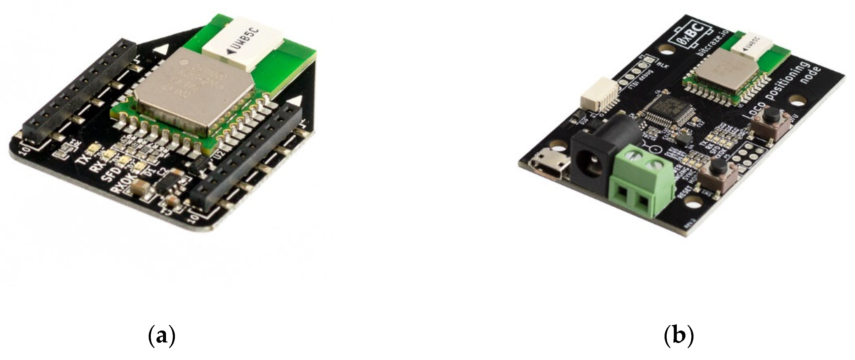
Figure 4.
(a) Configuration 1, where all anchors are placed in the same horizontal plane 40 cm above ground covering the area of 4×3 m; (b) Configuration 2, similar to Configuration 1 with additional anchor in the center at the height of 2 m; (c) Configuration 3 with two anchors equally spaced at the height of 2 m; (d) Configuration 4 with three anchors in the form of a triangle at one plane and 3 symmetrical upside-down on the opposite plane.
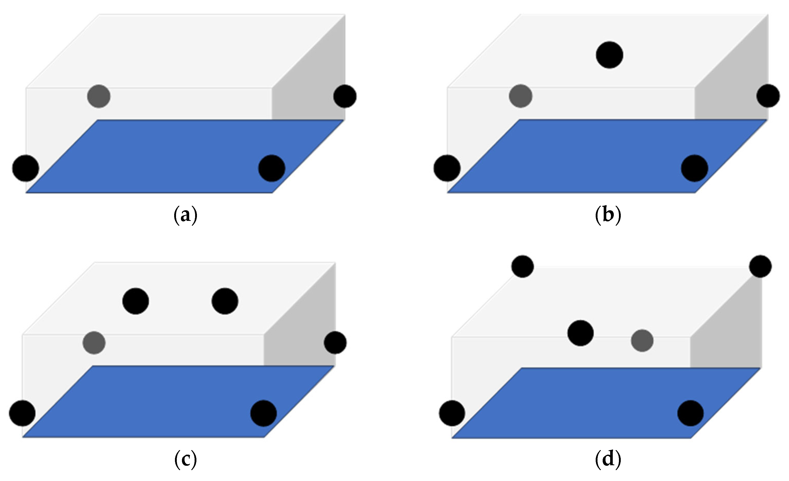
Figure 5.
The positions at which the UAV was fixed are depicted with red x-es. These positions were selected to provide a relatively low PDOP and to test the localization accuracy at different heights.
Figure 5.
The positions at which the UAV was fixed are depicted with red x-es. These positions were selected to provide a relatively low PDOP and to test the localization accuracy at different heights.
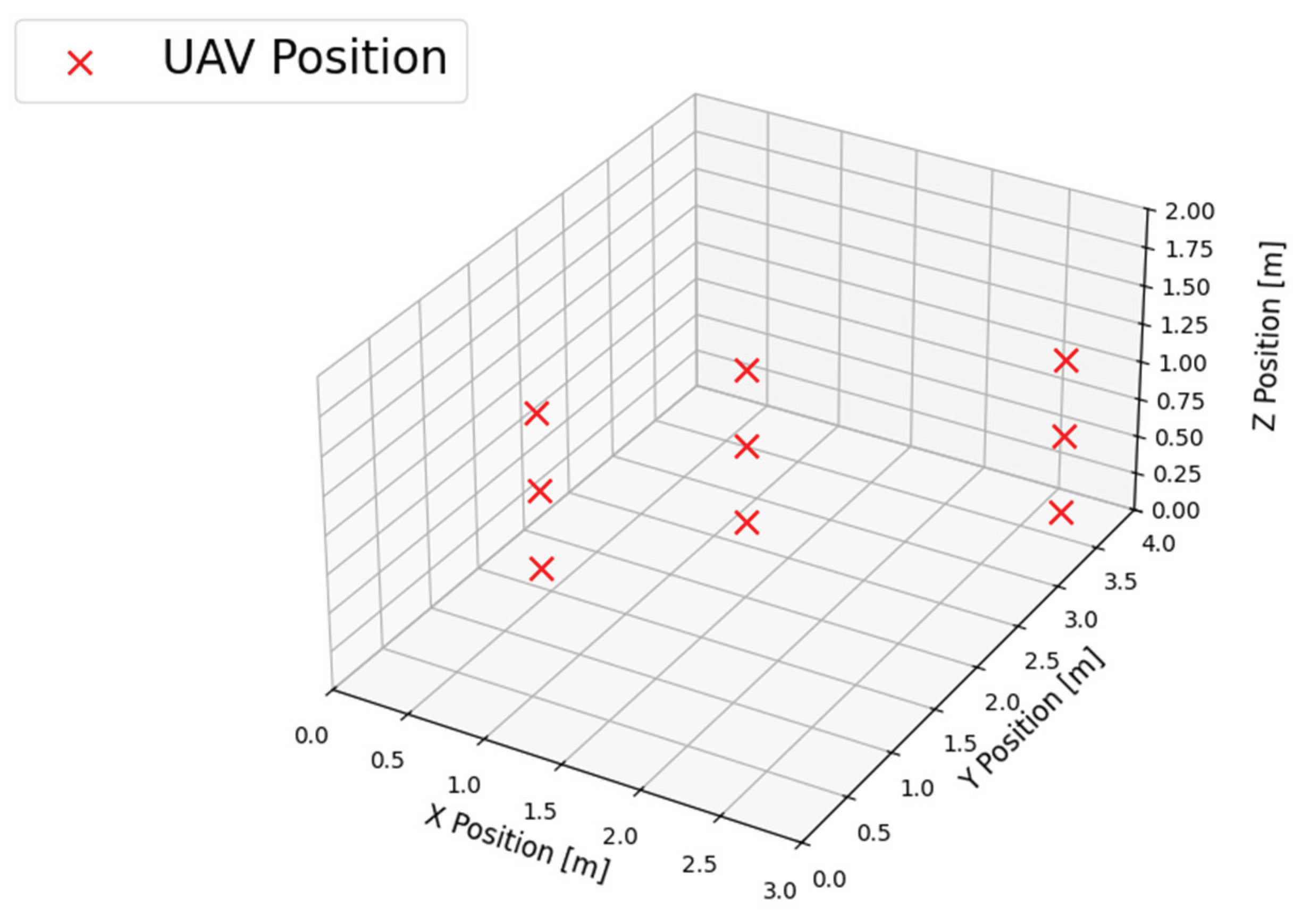
Figure 6.
3D scatter plots for three different horizontal locations and three different heights. (a) Point 1 corresponds to the location of (0.75, 1.0) m, and P3 corresponds to the location of (3.0, 3.0) m; (b) Point 2 corresponds to the location of (1.5, 2.0) m; (c) Point 3 corresponds to the location of (3.0, 3.0) m.
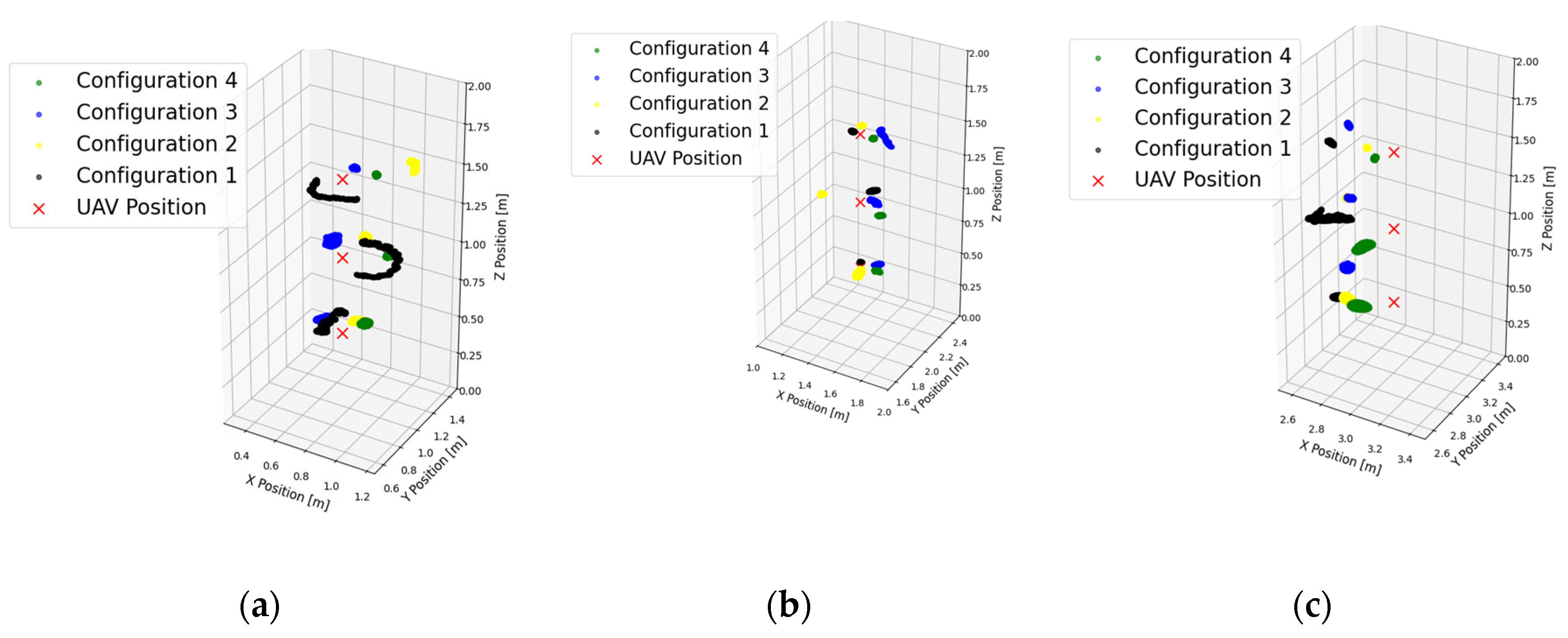

Table 1.
Four configurations of UWB anchors were used in the experiments.
| Feature | Configuration 1 | Configuration 2 | Configuration 3 | Configuration 4 |
|---|---|---|---|---|
| Number of anchors | 4 | 5 | 6 | 6 |
| Layout of anchors | Same horizontal plane at 40 cm height, 2D rectangle covering the area of 4×3 m | Same as Configuration 1, with one elevated central anchor | Same as Configuration 1, with two elevated central anchors | Three anchors at 40 cm, and three anchors elevated to 2 m |
| Vertical diversity | None | Medium | High | High |
| Additional anchor(s) | None | One at (1.5, 2, 2) m | Two at (1, 1, 2) m and (1, 3, 2) m | Two symmetrical triangles |
| Purpose | Baseline setup, minimal number of anchors required for (2)3D trilateration | Test on how a minimal 3D geometry affects vertical accuracy | Improving 3D trilateration by adding an additional elevated anchor | Maximizing spatial coverage and minimizing geometric distortion |
| Expected effects | Poor z-axis accuracy due to coplanar geometry (high VDOP) | Improvement in z-axis accuracy, similar horizontal accuracy to Configuration 1 | Further improvement in z-axis accuracy and reduced RMSE overall | Best overall accuracy |
Table 2.
Average RMSE and STDEV in meters for all three test points and three different heights without the usage of a laser altimeter.
Table 2.
Average RMSE and STDEV in meters for all three test points and three different heights without the usage of a laser altimeter.
| Ave. RMSE x | Ave. RMSE y | Ave. RMSE z | STDEV x | STDEV y | STDEV z | |
|---|---|---|---|---|---|---|
| Configuration 1 | 0.1750 | 0.1713 | 1.1604 | 0.0282 | 0.0206 | 0.1735 |
| Configuration 2 | 0.1320 | 0.1389 | 0.1367 | 0.0305 | 0.0222 | 0.0353 |
| Configuration 3 | 0.1681 | 0.1319 | 0.1286 | 0.0441 | 0.0370 | 0.0282 |
| Configuration 4 | 0.1223 | 0.1504 | 0.1064 | 0.0106 | 0.0106 | 0.0061 |
Table 3.
The values of PDOP in the tested positions for each configuration.
| Configuration 1 | Configuration 2 | Configuration 3 | Configuration 4 | |
|---|---|---|---|---|
| P1 H1 | 10.9248 | 1.7457 | 1.3513 | 1.4204 |
| P1 H2 | 2.2062 | 1.7119 | 1.3910 | 1.4594 |
| P1 H3 | 1.6395 | 1.5346 | 1.3943 | 1.3883 |
| P2 H1 | 13.9789 | 1.4132 | 1.3912 | 1.3339 |
| P2 H2 | 2.5895 | 1.3773 | 1.4840 | 1.4128 |
| P2 H3 | 1.7396 | 1.3443 | 1.5185 | 1.4027 |
| P3 H1 | 11.6819 | 2.0236 | 2.0297 | 1.3601 |
| P3 H2 | 2.2947 | 1.8850 | 1.9123 | 1.4272 |
| P3 H3 | 1.6581 | 1.5703 | 1.5481 | 1.5064 |
Disclaimer/Publisher’s Note: The statements, opinions and data contained in all publications are solely those of the individual author(s) and contributor(s) and not of MDPI and/or the editor(s). MDPI and/or the editor(s) disclaim responsibility for any injury to people or property resulting from any ideas, methods, instructions or products referred to in the content. |
© 2025 by the authors. Licensee MDPI, Basel, Switzerland. This article is an open access article distributed under the terms and conditions of the Creative Commons Attribution (CC BY) license (http://creativecommons.org/licenses/by/4.0/).
Copyright: This open access article is published under a Creative Commons CC BY 4.0 license, which permit the free download, distribution, and reuse, provided that the author and preprint are cited in any reuse.


