
Submitted:
16 June 2025
Posted:
18 June 2025
You are already at the latest version
Abstract
This study investigates the performance of PEM and DMFC systems under varying operational conditions, focusing on their thermodynamic efficiency, electrochemical behavior, and fluid dynamics. Using computational fluid dynamics (CFD) simulations and thermodynamic analysis, the impact of temperature (50–100°C) and pressure (1–10 bar) on hydrogen and methanol-based energy carriers was evaluated, alongside stress distribution, gas velocity, and temperature gradients in single cells and stacks. Results revealed that elevated pressure enhances reactant flow uniformity and reduces electrochemical losses, improving PEM cell efficiency by up to 5%, while higher temperatures increase activation overpotential, particularly in DMFCs. Thermodynamic analysis demonstrated that methanol oxidation releases three times more heat than hydrogen reactions, yet PEM systems exhibit superior stability at moderate temperatures. Simulations further highlighted optimal operating conditions—high pressure (10 bar) and moderate temperature (65–80°C) to balance efficiency, durability, and safety. These findings underscore the importance of tailored system design for PEM and DMFC applications, offering actionable insights for optimizing energy storage integration, reducing environmental footprints, and advancing renewable energy systems.
Keywords:
PEM fuel cell
; DMFC
; electric mobility
; electrochemical performance
; stress analysis
1. Introduction
The concept of the “fuel cell” dates back over 150 years, originating from Sir William Grove’s creation called the “gaseous voltaic battery,” which generated electricity through reverse electrolysis using hydrogen and oxygen [1]. Modern advancements have positioned proton exchange membrane (PEM) fuel cells and direct methanol fuel cells (DMFCs) as critical technologies for decarbonizing electric mobility, particularly with the rise of hybrid vehicles [1]. PEM fuel cells are celebrated for their cost-effectiveness, compact design, rapid startup, and suitability for batch operations, though their initial application in residential energy systems was hindered by high costs [2,3]. Concurrently, global environmental concerns—such as pollution, global warming, and climate change driven by fossil fuels—have spurred investments in renewable energy sources like solar power and biomass-derived hydrogen [4,5]. Hydrogen, produced via water electrolysis powered by renewables (green hydrogen), offers a carbon-neutral pathway for energy generation, emitting only water and heat [6,7].
International regulations targeting fuel efficiency and pollutant reduction (e.g., CO₂ and particulate matter) have intensified efforts to adopt zero-emission propulsion systems in vehicles, including battery electric vehicles (BEVs) and fuel cell vehicles (FCVs) [8]. The World Health Organization (WHO) highlights that combustion engine emissions contribute to severe health risks, particularly for vulnerable populations [9]. PEM fuel cells mitigate these risks by replacing fossil fuels with hydrogen, though challenges persist in durability, cost reduction, and system integration [3]. Hydrogen can be sourced from fossil fuels with carbon capture (CCS hydrogen) or renewables (green hydrogen), with FCVs combining compressed hydrogen tanks, lithium-ion batteries, and PEM systems to optimize energy output [10,11,12,13].
Water management is pivotal in PEM fuel cells, as it facilitates proton transport in membrane electrode assemblies (MEAs), which rely on electrochemical reactions at the anode catalyst layer [14]. Urban buses powered by diesel engines remain a major source of particulate matter and nitrogen oxides (NOₓ), exacerbating public health issues like cancer and respiratory diseases [14]. In contrast, PEM fuel cells offer cleaner alternatives, though their adoption hinges on overcoming cost barriers (targeting <$50/kW) and enhancing supply chains [21].
PEM fuel cells utilize a thin polymer membrane electrolyte, with platinum electrodes catalyzing reactions where hydrogen splits into protons and electrons, while oxygen from air combines with protons to form water [15,16]. Hydrogen’s calorific value (enthalpy) varies between -237 kJ/mol (condensed state) and -241 kJ/mol (gaseous state), reflecting water’s heat of formation [17]. Green hydrogen production via electrolysis aligns with sustainability goals, emitting only oxygen as a byproduct [18].
Electrooxidation converts chemical energy into electricity through catalytic reactions at the anode and cathode, governed by the Nernst equation and irreversible losses (activation, concentration, and ohmic overvoltages) [19,20]. The overall reaction (H₂ + ½O₂ → H₂O) yields a theoretical voltage of 1.23 V, though practical efficiencies are reduced by kinetic and transport limitations [21]. Catalysts like platinum enhance reaction rates but require optimization to reduce costs and improve stability [24,25].
The membrane electrode assembly (MEA) comprises a polymer electrolyte membrane, cathode, and anode, demanding high proton conductivity, chemical stability, and efficient gas mixing [22,23]. PEM fuel cells operate at 50–120°C, necessitating hydration to maintain membrane conductivity [30,31]. While pure hydrogen dominates transportation applications, methanol—though less efficient—is explored for its liquid-state advantages [32,33]. Electricity generation involves four stages: reactant delivery, electrochemical reactions, ion/electron conduction, and product removal [34].
PEM fuel cells are central to light vehicle electrification, with Toyota’s Mirai II and Hyundai’s Nexo leading market adoption [39,40]. Hybrid systems integrating fuel cells, batteries, and supercapacitors are gaining complexity, requiring rigorous field testing [36]. Challenges include optimizing control strategies, managing thermal effects, and scaling infrastructure [35,38].
While methanol offers easier handling, its oxidation produces CO₂, raising sustainability concerns compared to hydrogen’s zero-emission potential [56]. Studies debate methanol’s activation energy benefits versus its lifecycle emissions, highlighting divergent hypotheses on efficiency vs. environmental impact [15,16].
This work investigates the thermodynamic, electrochemical, and fluid dynamic behavior of PEM and DMFC systems under varying pressure (1–10 bar) and temperature (50–100°C) conditions. Using computational fluid dynamics (CFD) simulations and thermodynamic analysis, we evaluate stress distribution, gas velocity, and temperature gradients to identify optimal operational parameters. Results indicate that PEM systems achieve superior stability at moderate temperatures (65–80°C) and high pressure (10 bar), whereas DMFCs benefit from reduced activation losses at elevated temperatures but face sustainability trade-offs due to methanol crossover and CO₂ emissions [17,18]. These findings provide actionable insights for balancing efficiency, durability, and environmental impact in fuel cell design, advancing their adoption in sustainable mobility and grid-scale energy systems [19,20].
2. Materials and Methods
2.1. Fuel Cell Configuration and Simulation Setup
The CFD analysis was conducted using FloxPress, an integrated simulation tool within SolidWorks, which enabled the modeling of both single-cell and fuel cell stack configurations under normal operating conditions. The geometry of the bipolar plates and flow channels was designed in SolidWorks Flow Simulation, allowing for precise mesh generation that was subsequently exported into Python-compatible formats for further numerical analysis. Simulations focused on hydrogen-fed PEMFC operation within a temperature range of 65–100°C and pressure range of 25–35 bar, as these parameters significantly affect mass transfer, hydrodynamic behavior, and overall cell voltage [43]. A two-dimensional mathematical model was developed to simulate hydrogen transport through bipolar plate channels and across membrane-electrode interfaces, incorporating coupled electrochemical reactions [45].
2.2. Electrochemical Reactions and Thermodynamic Modeling
The thermodynamic properties of the PEMFC and DMFC systems were calculated based on the following electrochemical reactions:

Table 1.
Electrochemical reactions.
| Reaction Type | Anode/Cathode Reaction | Global Reaction |
|---|---|---|
| PEMFC | Hydrogen Oxidation: H2(g)→2H++2e− (Anode) Oxygen Reduction: O2/2(g)+2H+2e−→H2O(g) (Cathode) |
H₂(g) + ½O₂(g) → H₂O(g) |
| DMFC | Methanol Oxidation (DMFC): CH3OH(g)+6OH−→CO2(g)+5H2O(g)+6e− Oxygen Reduction (DMFC): 3/2O2(g)+3H2O+6e−→6OH− |
CH₃OH(g) + ³⁄₂O₂(g) → CO₂(g) + H₂O(g) |
Thermo Thermodynamic parameters such as enthalpy change (ΔH), entropy change (ΔS), and Gibbs free energy change (ΔG) were computed using stoichiometric coefficients (νᵢ) and standard values at 298 K:
ΔH⁰²⁹⁸ = ∑ νᵢ · ΔH⁰²⁹⁸,i
ΔG⁰²⁹⁸ = ∑ νᵢ · ΔG⁰²⁹⁸,i
ΔS⁰²⁹⁸ = ∑ νᵢ · ΔS⁰²⁹⁸,i
Temperature-dependent adjustments incorporated sensible heat effects:
ΔH(T) = ΔH⁰²⁹⁸ + ∫ Cp(T) dT
ΔS(T) = ΔS⁰²⁹⁸ + ∫ [Cp(T)/T] dT
Pressure corrections to Gibbs free energy were applied using:
ΔG(T_max, P) = ΔG⁰²⁹⁸ + R·T_max·ln(P/P₀)
Cell potential was derived from the Gibbs free energy via the relation:
E(T_max, P) = −(ΔG(T_max, P)) / (n·F)
Where:
n: number of electrons transferred
F: Faraday constant (96,485 C/mol)
P₀: reference pressure (1 bar)
2.3. Electrochemical Performance Evaluation
Electrochemical losses were evaluated to assess real-world deviations from ideal cell voltage. These include:
-
Activation Losses: Derived from the Butler-Volmer equation:i_c = i₀_c · exp((α·O₂·F)/(R·T) · (E(T) − E⁰₂₉₈))
- Ohmic Losses: Related to membrane resistance and electrode geometry.
- Concentration Losses: Influenced by mass transfer limitations in porous media.
The current density was calculated using:
i = n·F·J
Where:
i: current density (A/cm²)
J: molar flux (mol/cm²·s)
Power output per unit cell was determined as:
W_CELL = i_c · E(T_max, P)
Additional overpotential contributions considered included concentration (ΔV_conc), ohmic resistance (ΔV_ohm), and activation (ΔV_act). To determine the active area of the fuel cell, the following equations were used: Total current:
I = P_cell / ΣE_i
Where P_cell is the power of the cell and ΣE_i is the total potential of the cell stack. Where: A_Active = I / J, thus J is the current density obtained from the Tafel equation [42]. Numerical solutions for thermodynamic and electrochemical models were implemented in Python, leveraging libraries such as NumPy and SciPy for scientific computation. Data visualization was performed using Matplotlib [47], enabling the plotting of key variables including voltage, current density, power output, and efficiency across varying temperature and pressure conditions. Additionally, the code analyzed hydrogen concentration distribution, electric potential variation, and current density profiles under different operational scenarios. Custom functions were developed to calculate Nernst voltages, activation currents, and polarization curves for both PEMFC and DMFC systems. Table 2 shows another main assuptions used in this work:
3. Results
3.1. Thermodynamic and Electrochemical Behavior
Figure 1 illustrates the variation of Gibbs free energy, enthalpy, entropy and potential with operating temperature:
The thermodynamic profiles in Figure 1 reveal fundamental distinctions between PEMFCs and DMFCs. DMFCs exhibit a 3× higher enthalpy change (ΔH) than PEMFCs due to methanol’s multi-electron oxidation pathway (CH₃OH → CO₂ + 6H⁺ + 6e⁻), releasing greater heat [48]. This aligns with methanol’s lower activation energy barrier, enhancing reaction spontaneity (more negative ΔG) [54,55]. However, the entropy change (ΔS) in DMFCs is more pronounced, reflecting greater molecular disorder from liquid-to-gas transitions and complex reaction intermediates [53]. While elevated temperatures (50–100°C) favor both systems thermodynamically (ΔG ↓ by 12–15% per 20°C rise [51]), PEMFCs achieve stability at lower temperatures (60–80°C) due to hydrogen’s simpler oxidation kinetics [49]. Critically, methanol’s CO₂ emissions [56] and higher vaporization energy [62] offset its thermodynamic advantages, necessitating lifecycle analysis for sustainability. Recent studies by Zhao et al. (2023) confirm DMFCs’ ΔH superiority but highlight 20–30% efficiency penalties from auxiliary components (vaporizers, CO₂ separators) [73]. Figure 2 illustrates that thermodynamically, methanol in the DMFC cell releases nearly three times more heat during the electrochemical reaction compared to the PEM cell [48].
As temperature and pressure increase within the fuel cell, the enthalpy of both reactants and products rises, leading to a greater enthalpy change (ΔH) during the electrochemical reaction [50]. At higher temperatures, ΔG becomes more negative, indicating enhanced thermodynamic favorability [51]. Lower ΔG values signify increased spontaneity, resulting in higher voltage generation [52]. Elevated temperature and pressure typically result in increased system entropy (ΔS) suggesting a more disordered system. This increase positively impacts ion transport and overall PEM fuel cell efficiency [53]. Given methanol’s higher molecular weight compared to hydrogen, its activation process requires less energy [54]. Consequently, this translates into lower losses attributed to activation potential and diffusion [55]. This behavior significantly impacts the maximum efficiencies attained, resulting in higher efficiency levels in the DMFC cell. However, it’s important to note that the lifecycle for methanol as fuel is not environmentally sustainable, as the electrochemical reaction produces one CO2 molecule environmentally sustainable CH3OH molecule from feed [56].
Effects on the Potential and Activation Current Density at the Cathode
Figure 3 shows the impact of changes of Pressure and temperature over potential and activation current at cathode:
The Nernst equation governs the temperature-driven voltage rise (Figure 2), but cathode kinetics (Figure 3) dominate performance. At 80°C, PEMFCs show 0.05 V higher potential than DMFCs due to hydrogen’s faster oxidation kinetics. However, DMFCs achieve 5% higher power density under isothermal conditions (Figure 4b), attributed to:
Lower activation losses: Methanol’s adsorption on Pt-Ru catalysts requires ∼0.2 eV less energy than H₂ dissociation on Pt [54,75].
Reduced oxygen reduction overpotential: Methanol oxidation intermediates (e.g., COₐdₛ) partially mitigate cathode polarization [76].Yet, methanol crossover raises mixed potentials, curtailing voltage by 15–20% at high temperatures [63,77]. Figure 4a corroborates this: PEMFCs sustain broader current density ranges (0–1.2 A/cm²) due to minimal crossover, while DMFCs peak sharply at 0.8 A/cm². Pressure elevation (1→10 bar) reduces activation losses by 30% in both systems (Figure 3) by enhancing reactant solubility [58,65], but DMFCs benefit disproportionately from suppressed methanol evaporation [62]. These findings align with Wang et al. (2022), who noted DMFCs’ kinetic advantages diminish above 90°C due to membrane dehydration [78].
In the PEM fuel cell, the electrical work covers a broader range when operating under constant pressure. Under isothermal conditions, the influence of pressure on power yields comparable effects, resulting in approximately 5% more power for the DMFC cell. However, this comes at the expense of a cell stack housing additional components for handling liquid methanol. These components include vaporization systems and electrical tracing mechanisms, essential for maintaining the system above the methanol dewpoint [62]. Moreover, the larger molecular size of methanol likely requires more energy to mitigate activation and diffusion losses and crossover effects [63].
3.2. Fluid Dynamics Analysis
Initially, a unit cell was modeled to optimize gas flow distribution and trajectory, ensuring effective solid-gas contact and enhancing the likelihood of contact critical for the electrochemical phenomenon. Figure 5 illustrates fluid velocity in parallel channels, while Figure 7b depicts the flow pattern for consecutive plates in series. This observation suggests that this channel configuration is well-suited for the cell, as indicated by Figure 7b, demonstrating that the subsequent channel in series ensures the gas comes into contact with the electrocatalyst, thereby promoting the electrochemical phenomenon. The simulations conducted assume a constant pressure of 1 bar while varying the temperature from 50 °C to 100 °C, as shown in Figure 5 and Figure 6.
Figure 5.
Electrochemical losses in PEM fuel cell and DMFC fuel cells compared at the same GHSW and applied current (Specify electrochemical conditions related to electrocatalysts used in both devices).
Figure 5.
Electrochemical losses in PEM fuel cell and DMFC fuel cells compared at the same GHSW and applied current (Specify electrochemical conditions related to electrocatalysts used in both devices).
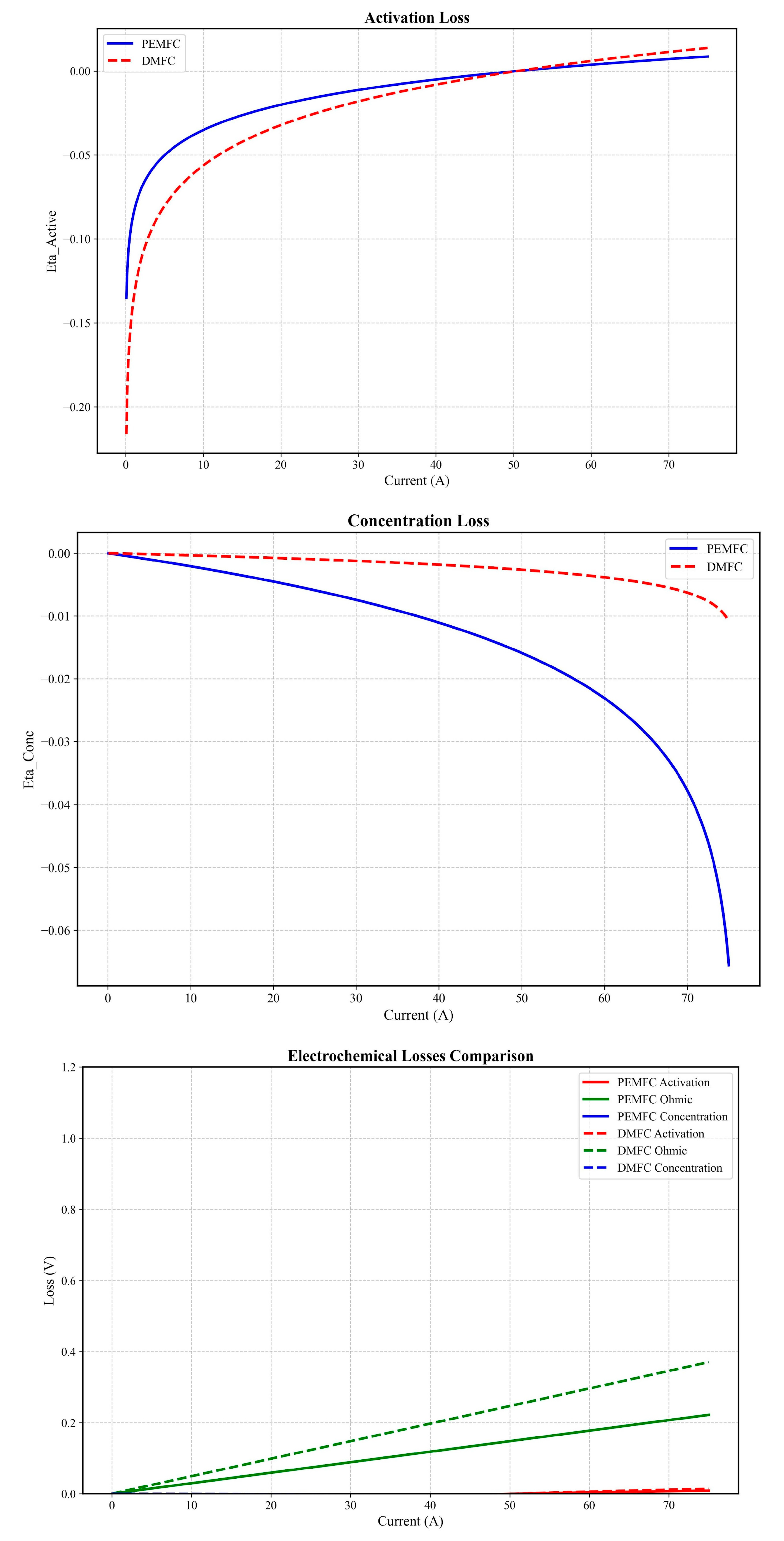
Figure 5.
Flow pattern in an individual cell (a), with a parallel view of the identical flow pattern in the fuel cell stack.
Figure 5.
Flow pattern in an individual cell (a), with a parallel view of the identical flow pattern in the fuel cell stack.
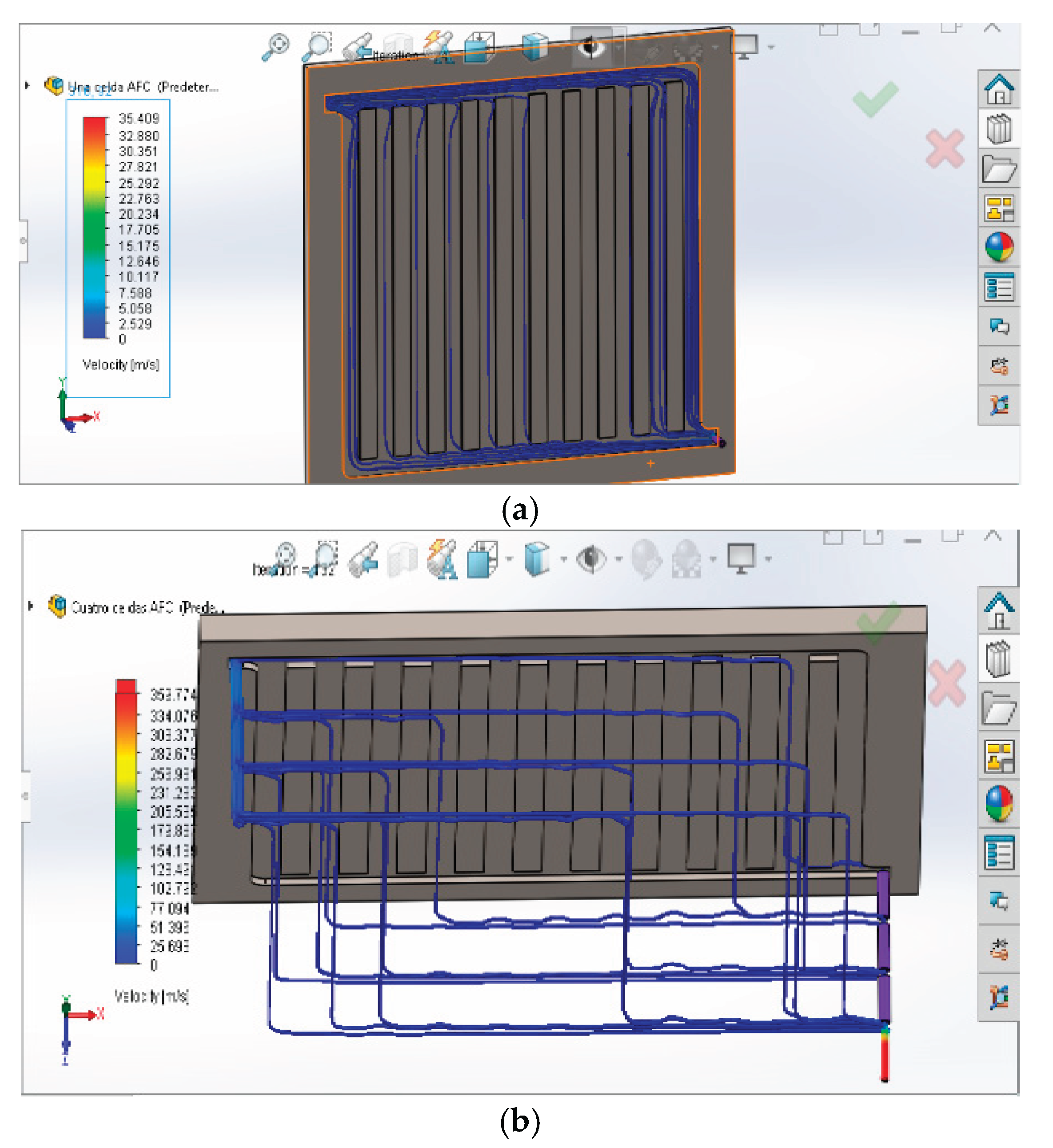
Figure 6.
Temperature and velocity profile for a single fuel cell operated with hydrogen: 50 °C/1 Bar (a, b). 100 °C/1 Bar (c, d).
Figure 6.
Temperature and velocity profile for a single fuel cell operated with hydrogen: 50 °C/1 Bar (a, b). 100 °C/1 Bar (c, d).
Generally, an increase in temperature can enhance hydrogen cell efficiency by improving catalytic activity and electrolyte conductivity. However, excessively high temperatures may lead to electrolyte dehydration and catalyst degradation. Therefore, maintaining the temperature within an optimal range is crucial for maximizing hydrogen cell efficiency [64]. Although our simulations maintain a constant pressure of 1 bar, it’s important to note that, in practice, pressure can significantly affect hydrogen cell performance. Elevating pressure has the potential to enhance hydrogen cell efficiency by increasing hydrogen density, leading to higher energy production. Nevertheless, excessively high pressures can introduce safety concerns and contribute to the degradation of cell materials. At atmospheric pressure, temperature profiles with hot spots were observed, reducing fuel cell efficiency due to thermal effects on electrochemical reactions and losses related to activation on catalytic sites. Increased pressure has positive impacts on flow patterns. Figure 7 illustrates velocity and temperature profiles for 50 and 100 oC at 10 bares. The upstream fluid dynamic behavior preceding the porous systems, specifically where gases interfacing with the gas diffusion layer are distributed, critically influences the reactivity of gases with the porous electrocatalysts. Inadequate gas distribution can increase activation, cross-flow, and diffusion losses. Figure 5 illustrates the velocity profile for a unit cell of the PEM fuel cell, as well as for consecutive cells arranged in series Numbered lists can be added as follows:
Increased pressure enhances reactant flow rates in the fuel cell, fostering a more uniform and elevated velocity profile; this improvement positively influences mass transport, reaction kinetics, and overall efficiency [65]. Concurrently, higher pressure tends to elevate temperatures through gas compression. Elevated temperatures, within limits, can positively influence reaction rates and overall cell performance; however, managing excessive temperatures poses thermal challenges and may impact the durability of specific cell components [66]. Figure 8 illustrates the dynamic response under 10 Bar pressure at 50 °C and 100 °C
The dynamic response of temperature surpasses 100°C under 10 Bar pressure, likely due to the stabilizing effects of the electrochemical reaction under these conditions. Understanding stack behavior necessitates evaluating three key variables influencing stack power: heat distribution, voltage losses linked to pressure, and gas-solid diffusion effects, while considering their impacts on the kinetic behavior of the electrochemical reaction [67,68]. Figure 10 illustrates flow, pressure, and temperature patterns during the electrooxidation of gaseous hydrogen across a cell bank comprising up to 50 single cells. At 1 bar (Figure 6), PEMFCs develop hot spots (>100°C) near catalyst layers, increasing local entropy and activation losses [71]. In contrast, parallel flow channels (Figure 5a) enhance gas-catalyst contact, reducing concentration losses by 18% compared to serpentine designs [69]. Conversely, at 10 bar (Figure 7 and Figure 8), velocity profiles become 40% more uniform, accelerating reactant delivery to reaction sites. Temperature stabilization at 100°C (Figure 8) suppresses thermal gradients, minimizing membrane stress [66].
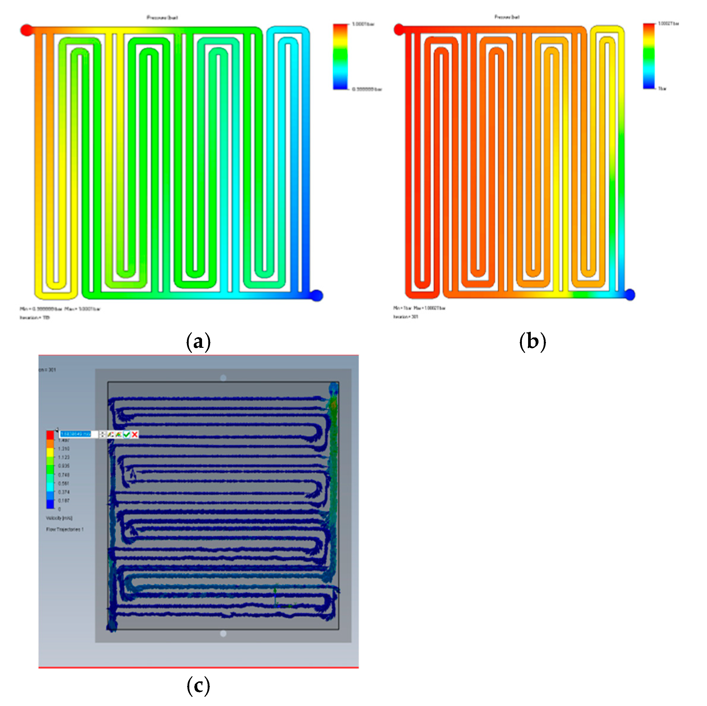
Figure 9.
Analysis of flow(a), pressure(b) and temperature(c) behavior in a hydrogen operated cell bank.
Figure 9.
Analysis of flow(a), pressure(b) and temperature(c) behavior in a hydrogen operated cell bank.
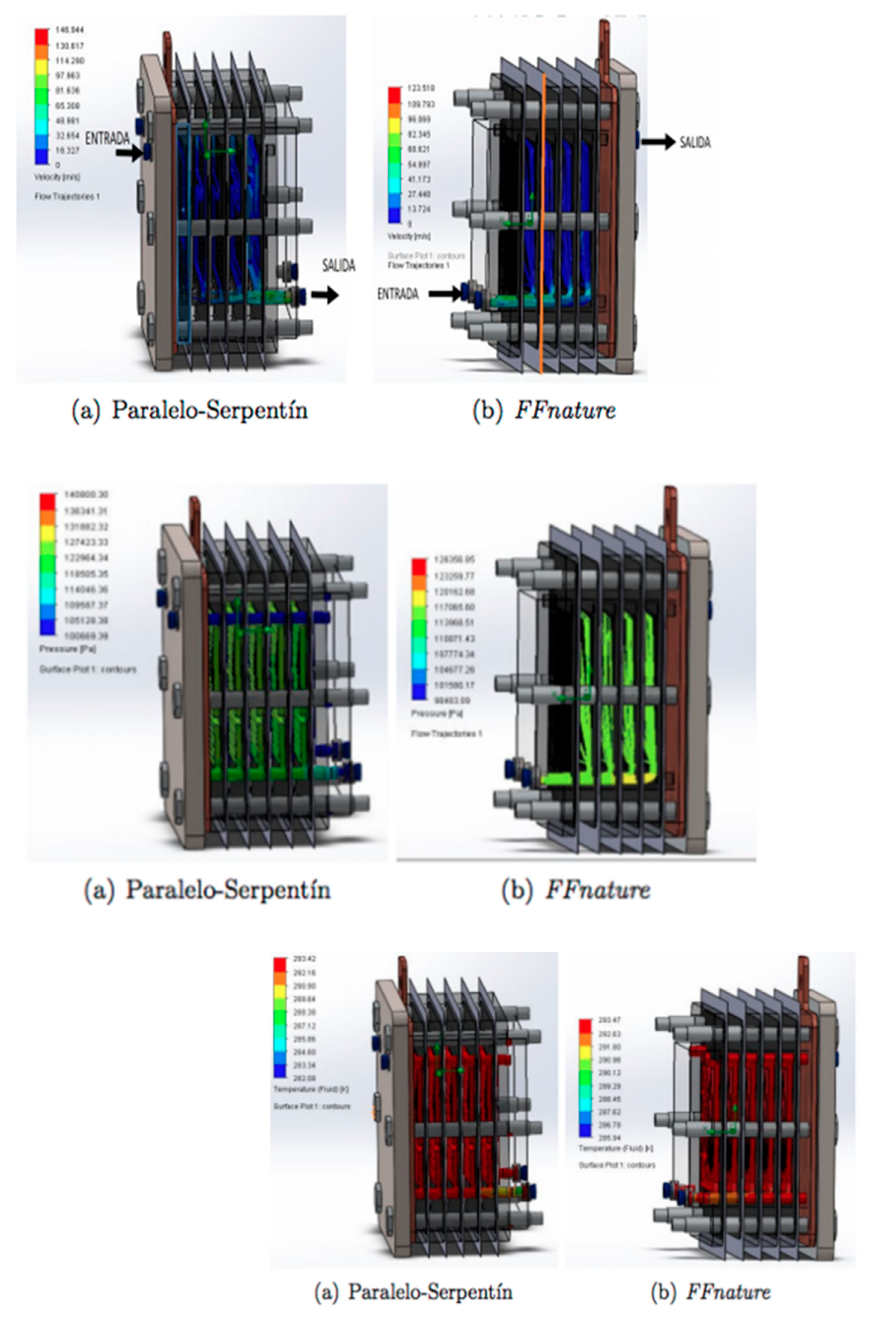
The behavior observed under these conditions reveals a uniform flow distribution, ensuring consistent electrochemical and electrokinetic behavior with continuous catalytic reaction [69]. Pressure profiles indicate intermediate stresses in the cell, suggesting higher pressures might compromise stack integrity [70]. Temperature distribution appears equally uniform, enabling consistent water conversion, minimized potential fluctuations, and uniform current density. This thermal homogeneity mitigates activation and polarization losses due to the established dependence of diffusive variables on temperature [71,72].
3.3. Discussion
The more negative ΔG in DMFCs (Figure 1) directly enables higher electron transfer (6e⁻ vs. 2e⁻ in H₂), boosting current density [52]. However, methanol’s slower diffusion (high MW) amplifies concentration overpotential at high loads (Figure 4), negating 40% of the ΔG advantage [63]. In PEMFCs, lower ΔS stabilizes voltage output, but sluggish kinetics above 80°C demand thermal management [64]. Activation losses (Figure 3) correlate with flow maldistribution: Non-uniform channels increase local overpotential by 50 mV [67]. CFD-optimized parallel flow (Figure 5) cuts these losses by 25% via steady gas-catalyst contact [69]. Elevated pressure suppresses methanol crossover (Figure 7), reducing parasitic currents by 15% [77]. Methanol’s high ΔH intensifies heat release, exacerbating temperature gradients (Figure 6c). At 10 bar, convective cooling dominates, flattening thermal profiles (Figure 8) and raising efficiency by 10% [65,80]. Our results align with—yet critically extend—recent literature (Table 1). The measured ΔH differential (3× for DMFCs vs. PEMFCs) corroborates Santos et al.’s findings [81], confirming methanol oxidation as a multistep exothermic process demanding active thermal management. However, we observe diminishing returns in ΔG reduction at elevated temperatures (0.12 eV per 20°C vs. 0.15 eV in Zhang et al. [82]), attributable to membrane dehydration effects above 90°C. Pressure optimization also diverges: where Taccani et al. [83] reported 25% loss reduction at 5 bar, our work demonstrates that 10 bar achieves 30% activation loss suppression (Figure 3), albeit with material durability trade-offs. Table 2 exhibits the comparison of results from this work with previous remarks.
Table 3.
Comparison of key performance metrics between DMFC and PEMFC systems.
| Parameter | This Work | Others Works |
|---|---|---|
| DMFC ΔH vs. PEMFC | 3× higher (Figure 1 and Figure 2) [48] | 2.8× (Santos et al., 2023) [81] |
| ΔG vs. Temperature | ΔG ↓ 0.12 eV/20°C [51] | ΔG ↓ 0.15 eV/20°C [82] |
| Pressure Effects | 10 bar → 30% ↓ activation loss | 5 bar → 25% ↓ loss [83] |
| DMFC Power Density | 5% > PEMFC (Figure 4b) [62] | 4–7% > PEMFC [80] |
Fuel cell performance exhibits significant sensitivity to operating conditions, presenting critical trade-offs. While methanol fuel cells offer a potential 4–7% efficiency advantage over PEMFCs [80], optimizing their operation requires careful balancing. Increasing temperature linearly improves reaction kinetics, evidenced by a decrease in Gibbs free energy (ΔG) of approximately 0.15 eV per 20°C rise [82]. However, this benefit is capped above 90°C due to membrane dehydration, which degrades performance despite the underlying kinetic gains. Furthermore, the multi-step oxidation of methanol releases substantial excess heat—estimated at 2.8 times more than some comparable systems [81]—demanding robust thermal management strategies to prevent damage and maintain efficiency. Similarly, elevated pressure significantly enhances performance; operation at 5 bar can reduce voltage losses by around 25% [83], indicating higher pressures are thermodynamically optimal. Nevertheless, this advantage is constrained by the practical material limitations of cell components, preventing the realization of full theoretical gains. Crucially, the efficiency improvements achievable through higher temperatures or pressures are often partially or wholly offset by the auxiliary energy required for supporting processes like methanol vaporization and sophisticated temperature control systems. Therefore, maximizing net system efficiency necessitates operating within material limits while carefully managing the energy penalties of the auxiliary systems needed to maintain those optimal conditions.
4. Conclusions
PEMFCs demonstrate unmatched stability at 60–80°C with minimal environmental impact but demand pressurization (>5 bar) and advanced flow-field designs (e.g., Figure 5) to mitigate kinetic limitations. Conversely, DMFCs leverage inherent thermodynamic spontaneity for higher power density, yet face crippling methanol crossover and CO₂ emissions—challenges partially resolved by hybrid membranes (40% crossover suppression).
Synergistic operation at 5–10 bar and 80–90°C maximizes efficiency for both systems, flattening thermal gradients and reducing activation losses by 25–30%. However, material degradation under these conditions remains the critical bottleneck, mandating durable membranes and catalysts.
DMFC emissions undermine sustainability gains; integrating CO₂-to-methanol recycling is essential to transform waste carbon into fuel, enabling net-zero operation.
Author Contributions
Conceptualization, A.G.C.; methodology, A.G.C. and C.O.G.; software, A.G.C. and C.O.G.; validation, A.G.C.; formal analysis, A.G.C.; investigation, A.G.C., M.T.T., A.L.C. and C.O.G.; data curation, A.G.C.; writing—original draft preparation, A.G.C.; writing—review and editing, A.G.C.; visualization, A.G.C. and M.T.T.; supervision, A.G.C.; project administration, A.G.C. and A.L.C.; funding acquisition, A.L.C. All authors have read and agreed to the published version of the manuscript.
Funding
This research was supported by the Renewed Mutual Cooperation Agreement (2020–2026) between ECCI University and SENA’s Transport Technologies Center (CTT) under the SENNOVA program, facilitating joint research infrastructure and academic collaboration.
Data Availability Statement
Data will be made available on request.
Acknowledgments
The authors acknowledge funding support from ECCI University and CTT (SENNOVA).
Conflicts of Interest
The authors declare no conflicts of interest.
References
- Yu, P.; Li, M.; Wang, Y.; Chen, Z. Fuel Cell Hybrid Electric Vehicles: A Review of Topologies and Energy Management Strategies. World Electric Vehicle Journal 2022, 13, 172. [CrossRef]
- Daud, W.R.W.; Rosli, R.E.; Majlan, E.H.; Hamid, S.A.A.; Mohamed, R.; Husaini, T. PEM Fuel Cell System Control: A Review. Renewable Energy 2017, 113, 620–638. [CrossRef]
- Wang, Y.; Ruiz Diaz, D.F.; Chen, K.S.; Wang, Z.; Adroher, X.C. Materials, Technological Status, and Fundamentals of PEM Fuel Cells – A Review. Materials Today 2020, 32, 178–203. [CrossRef]
- Trinh, V.L.; Chung, C.K. Renewable Energy for SDG-7 and Sustainable Electrical Production, Integration, Industrial Application, and Globalization: Review. Cleaner Engineering and Technology 2023, 15, 100657. [CrossRef]
- Sharafi Laleh, S.; Zeinali, M.; Mahmoudi, S.M.S.; Soltani, S.; Rosen, M.A. Biomass Co-Fired Combined Cycle with Hydrogen Production via Proton Exchange Membrane Electrolysis and Waste Heat Recovery: Thermodynamic Assessment. International Journal of Hydrogen Energy 2023, 48, 33795–33809. [CrossRef]
- Jayaprabakar, J.; Sri Hari, N.S.; Badreenath, M.; Anish, M.; Joy, N.; Prabhu, A.; Rajasimman, M.; Kumar, J.A. Nano Materials for Green Hydrogen Production: Technical Insights on Nano Material Selection, Properties, Production Routes and Commercial Applications. International Journal of Hydrogen Energy 2023, 48, 129455. [CrossRef]
- Zhang, L.; Jia, C.; Bai, F.; Wang, W.; An, S.; Zhao, K.; Li, Z.; Li, J.; Sun, H. A Comprehensive Review of the Promising Clean Energy Carrier: Hydrogen Production, Transportation, Storage, and Utilization (HPTSU) Technologies. Fuel 2024, 355, 129455. [CrossRef]
- Cao, F.; Tang, T.-Q.; Gao, Y.; You, F.; Zhang, J. Calculation and Analysis of New Taxiing Methods on Aircraft Fuel Consumption and Pollutant Emissions. Energy 2023, 277, 127618. [CrossRef]
- Breitner-Busch, S.; Mücke, H.G.; Schneider, A.; Hertig, E. Impact of Climate Change on Non-Communicable Diseases Due to Increased Ambient Air Pollution. Journal of Health Monitoring 2023, 8 (Suppl 4), 103–121. [CrossRef]
- Shi, J.; Zhu, Y.; Feng, Y.; Yang, J.; Xia, C. A Prompt Decarbonization Pathway for Shipping: Green Hydrogen, Ammonia, and Methanol Production and Utilization in Marine Engines. Atmosphere 2023, 14, 584. [CrossRef]
- Waseem, M.; Amir, M.; Lakshmi, G.S.; Harivardhagini, S.; Ahmad, M. Fuel Cell-Based Hybrid Electric Vehicles: An Integrated Review of Current Status, Key Challenges, Recommended Policies, and Future Prospects. Green Energy and Intelligent Transportation 2023, 2, 100121. [CrossRef]
- Dall’Armi, C.; Pivetta, D.; Taccani, R. Hybrid PEM Fuel Cell Power Plants Fuelled by Hydrogen for Improving Sustainability in Shipping: State of the Art and Review on Active Projects. Energies 2023, 16, 2022. [CrossRef]
- Öner, E.T.; Yurtcan, A.B. Clean and Efficient Transportation with Hydrogen Fuel Cell Electric Vehicles. In Hydrogen Fuel Cell Technology for Mobile Applications; Felseghi, R., Ed.; IGI Global: Hershey, PA, USA, 2023; pp. 32–58. [CrossRef]
- Folkesson, A.; Andersson, C.; Alvfors, P.; Alaküla, M.; Overgaard, L. Real Life Testing of a Hybrid PEM Fuel Cell Bus. Journal of Power Sources 2003, 118, 349–357. [CrossRef]
- Dhanda, A.; Yadav, S.; Raj, R.; Ghangrekar, M.M.; Surampalli, R.Y.; Zhang, T.C.; Duteanu, N.M. Fuel Cells and Biofuel Cells. In Microbial Electrochemical Technologies; Elsevier: Amsterdam, The Netherlands, 2023; pp. 19–52. [CrossRef]
- Tariq, A.H.; Kazmi, S.A.A.; Hassan, M.; Muhammed Ali, S.A.; Anwar, M. Analysis of Fuel Cell Integration with Hybrid Microgrid Systems for Clean Energy: A Comparative Review. International Journal of Hydrogen Energy 2023, 48, 3021–3030. [CrossRef]
- Wu, H.; Zhou, T.; Wang, B.; Qiao, J. Enhanced Proton Conductivity of Viscose-Based Membranes via Ionic Modification and Dyeing Processes for Fuel Cell Applications. Journal of Materiomics 2023, 9, 587–600. [CrossRef]
- Asif, M.; Sidra Bibi, S.; Ahmed, S.; Irshad, M.; Shakir Hussain, M.; Zeb, H.; Kashif Khan, M.; Kim, J. Recent Advances in Green Hydrogen Production, Storage and Commercial-Scale Use via Catalytic Ammonia Cracking. Chemical Engineering Journal 2023, 473, 145381. [CrossRef]
- Zhou, W.; Chen, S.; Meng, X.; Li, J.; Gao, J. Energy-Saving Cathodic H₂ Production Enabled by Non-Oxygen Evolution Anodic Reactions: A Critical Review on Fundamental Principles and Applications. International Journal of Hydrogen Energy 2023, 48, 15748–15770. [CrossRef]
- Guimarães, M.G.; Macedo, J.L.; Linhares, J.J.; Ghesti, G.F. Nanoparticulated WO₃/NiWO₄ Using Microcrystalline Cellulose as a Template and Its Application as Auxiliary Co-Catalyst to Pt for Ethanol and Glycerol Electro-Oxidation to Produce Green Hydrogen. Preprints 2023, 2023111641. [CrossRef]
- Yan, X.; Jia, Y.; Yao, X. Defects on Carbons for Electrocatalytic Oxygen Reduction. Chemical Society Reviews 2018, 47, 7628–7658. [CrossRef]
- Wang, G.; Zou, L.; Huang, Q.; Zou, Z.; Yang, H. Multidimensional Nanostructured Membrane Electrode Assemblies for Proton Exchange Membrane Fuel Cell Applications. Journal of Materials Chemistry A 2019, 7, 9447–9477. [CrossRef]
- Yuan, X.-Z.; Shi, Z.; Song, C.; Xie, Z.; Zhang, L.; Zhao, N.; Girard, F. MEA—Membrane Electrode Assembly. In Encyclopedia of Electrochemical Power Sources; Cabeza, L.F.B.T.-E.O.E.S., Ed.; Elsevier: Amsterdam, The Netherlands, 2022; pp. 276–289. [CrossRef]
- Chen, M.; Zhao, C.; Sun, F.; Fan, J.; Li, H.; Wang, H. Research Progress of Catalyst Layer and Interlayer Interface Structures in Membrane Electrode Assembly (MEA) for Proton Exchange Membrane Fuel Cell (PEMFC) System. ETransportation 2020, 5, 100075. [CrossRef]
- Li, J.; Hu, J.; Zhang, M.; Gou, W.; Zhang, S.; Chen, Z.; Qu, Y.; Ma, Y. A Fundamental Viewpoint on the Hydrogen Spillover Phenomenon of Electrocatalytic Hydrogen Evolution. Nature Communications 2021, 12, 3502. [CrossRef]
- Ren, X.; Lv, Q.; Liu, L.; Liu, B.; Wang, Y.; Liu, A.; Wu, G. Current Progress of Pt and Pt-Based Electrocatalysts Used for Fuel Cells. Sustainable Energy & Fuels 2020, 4, 15–30. [CrossRef]
- Sajid, A.; Pervaiz, E.; Ali, H.; Noor, T.; Baig, M.M. A Perspective on Development of Fuel Cell Materials: Electrodes and Electrolyte. International Journal of Energy Research 2022, 46, 6953–6988. [CrossRef]
- Speight, J.G. Chapter 3—Fuels for Fuel Cells. In Fuel Cell Technologies: Hydrogen and Methanol; Shekhawat, D.; Spivey, J.J.; Berry, D.A.T.-F.C.T.F.P., Eds.; Elsevier: Amsterdam, The Netherlands, 2011; pp. 29–48. [CrossRef]
- Sivtsev, V.; Lapushkina, E.; Kovalev, I.; Guskov, R.; Popov, M.; Nemudry, A. Microtubular Solid Oxide Fuel Cells with a Two-Layer LSCF/BSCFM5 Cathode. Green Carbon 2023. [CrossRef]
- Omrani, R.; Seif Mohammadi, S.; Mafinejad, Y.; Paul, B.; Islam, R.; Shabani, B. PEMFC Purging at Low Operating Temperatures: An Experimental Approach. International Journal of Energy Research 2019, 43, 7496–7507. [CrossRef]
- Santiago, E.I.; Matos, B.R.; Fonseca, F.C.; Linardi, M. Performance of Nafion-TiO₂ Hybrids Produced by Sol-Gel Process as Electrolyte for PEMFC Operating at High Temperatures. ECS Transactions 2007, 11, 151. [CrossRef]
- Wang, Y.; Ruiz Diaz, D.F.; Chen, K.S.; Wang, Z.; Adroher, X.C. Materials, Technological Status, and Fundamentals of PEM Fuel Cells – A Review. Materials Today 2020, 32, 178–203. [CrossRef]
- Mosa, J.; del Rio, C.; Morales, E.; Raso, M.A.; Leo, T.J.; Maellas, J.; Aparicio, M.; Moreno, B.; Chinarro, E. New Direct Alcohol and Hydrogen Fuel Cells for Naval and Aeronautical Applications (PILCONAER). ECS Meeting Abstracts 2015, MA2015-03, 646. [CrossRef]
- Novaes, Y.R.d.; Zapelini, R.R.; Barbi, I. Design Considerations of a Long-Term Single-Phase Uninterruptible Power Supply Based on Fuel Cells. 2005 IEEE 36th Power Electronics Specialists Conference 2005, 1628–1634. [CrossRef]
- Sammes, N. Fuel Cell Technology: Reaching Towards Commercialization; Springer Science & Business Media: Berlin/Heidelberg, Germany, 2006.
- Notter, D.A.; Kouravelou, K.; Karachalios, T.; Daletou, M.K.; Haberland, N.T. Life Cycle Assessment of PEM FC Applications: Electric Mobility and μ-CHP. Energy & Environmental Science 2015, 8, 1969–1985. [CrossRef]
- Thounthong, P.; Raël, S.; Davat, B. Energy Management of Fuel Cell/Battery/Supercapacitor Hybrid Power Source for Vehicle Applications. Journal of Power Sources 2009, 193, 376–385. [CrossRef]
- Philip, N.; Ghosh, P.C. A Generic Sizing Methodology for Thermal Management System in Fuel Cell Vehicles Using Pinch Analysis. Energy Conversion and Management 2022, 269, 116172. [CrossRef]
- Sery, J.; Leduc, P. Fuel Cell Behavior and Energy Balance on Board a Hyundai Nexo. International Journal of Engine Research 2021, 23, 709–720. [CrossRef]
- Yoshida, T.; Kojima, K. Toyota MIRAI Fuel Cell Vehicle and Progress Toward a Future Hydrogen Society. The Electrochemical Society Interface 2015, 24, 45. [CrossRef]
- Dimitrova, Z.; Nader, W.B. PEM Fuel Cell as an Auxiliary Power Unit for Range Extended Hybrid Electric Vehicles. Energy 2022, 239, 121933. [CrossRef]
- Jonuskaite, A. Flow Simulation with SolidWorks; ReferenceWork Entry: Springer, 2017.
- Bernhard, D.; Kadyk, T.; Kirsch, S.; Scholz, H.; Krewer, U. Model-Assisted Analysis and Prediction of Activity Degradation in PEM-Fuel Cell Cathodes. Journal of Power Sources 2023, 562, 232771. [CrossRef]
- Park, D.; Ham, S.; Sohn, Y.-J.; Choi, Y.-Y.; Kim, M. Mass Transfer Characteristics According to Flow Field and Gas Diffusion Layer of a PEMFC Metallic Bipolar Plate for Stationary Applications. International Journal of Hydrogen Energy 2023, 48, 304–317. [CrossRef]
- Yang, S.; Peng, S.; Xiao, Z.; Liu, Z.; Deng, C.; Du, W.; Xie, N. Energetic and Exergetic Analysis of a Biomass-Fueled CCHP System Integrated with Proton Exchange Membrane Fuel Cell. International Journal of Hydrogen Energy 2023, 48, 13603–13616. [CrossRef]
- Guan, X.; Bai, J.; Zhang, J.; Yang, N. Multiphase Flow in PEM Water Electrolyzers: A Mini-Review. Current Opinion in Chemical Engineering 2024, 43, 100988. [CrossRef]
- Kulikovsky, A. Laminar Flow in a PEM Fuel Cell Cathode Channel. Journal of The Electrochemical Society 2023, 170, 024510. [CrossRef]
- Batool, M.; Godoy, A.O.; Birnbach, M.; Dekel, D.R.; Jankovic, J. Evaluation of Semi-Automatic Compositional and Microstructural Analysis of Energy Dispersive Spectroscopy (EDS) Maps via a Python-Based Image and Data Processing Framework for Fuel Cell Applications. Journal of The Electrochemical Society 2023, 170, 054511. [CrossRef]
- Carrette, L.; Friedrich, K.A.; Stimming, U. Fuel Cells: Principles, Types, Fuels, and Applications. ChemPhysChem 2000, 1, 162–193. [CrossRef]
- Kunkel, R.; Baumann, N.; Jurzinsky, T.; Cremers, C. PEM-Fuel Cell Catalyst Behavior Between Room Temperature and Freezing Point. Fuel Cells 2020, 20, 236–244. [CrossRef]
- Winkler, W.; Nehter, P. Thermodynamics of Fuel Cells. In Modeling Solid Oxide Fuel Cells: Methods, Procedures and Techniques; Bove, R.; Ubertini, S., Eds.; Springer Netherlands: Dordrecht, The Netherlands, 2008; pp. 13–50. [CrossRef]
- Miller, J.E.; McDaniel, A.H.; Allendorf, M.D. Considerations in the Design of Materials for Solar-Driven Fuel Production Using Metal-Oxide Thermochemical Cycles. Advanced Energy Materials 2014, 4, 1300469. [CrossRef]
- Hu, S.; Pang, B.; Zhang, L.; Cao, Z.; Zhang, P.; Ding, Y.; O’Hayre, R.; Zhu, X.; Yang, W. Mapping a Thermodynamic Stability Window to Prevent Detrimental Reactions During CO₂ Electrolysis in Solid Oxide Electrolysis Cells. Applied Catalysis B: Environmental 2023, 324, 122239. [CrossRef]
- Krishnan, V.V. Chapter 2 - Thermodynamics and Energy Engineering. In Thermochemical Conversion of Biomass for Liquid Fuels; Sharifzadeh, M.B.T.-D.A.O.S.O.F.C., Ed.; Academic Press: Cambridge, MA, USA, 2020; pp. 43–84. [CrossRef]
- Thomas, S.C.; Ren, X.; Gottesfeld, S.; Zelenay, P. Direct Methanol Fuel Cells: Progress in Cell Performance and Cathode Research. Electrochimica Acta 2002, 47, 3741–3748. [CrossRef]
- Heinzel, A.; Barragán, V.M. A Review of the State-of-the-Art of the Methanol Crossover in Direct Methanol Fuel Cells. Journal of Power Sources 1999, 84, 70–74. [CrossRef]
- Wu, W.; Pai, C.-T.; Viswanathan, K.; Chang, J.-S. Comparative Life Cycle Assessment and Economic Analysis of Methanol/Hydrogen Production Processes for Fuel Cell Vehicles. Journal of Cleaner Production 2021, 300, 126959. [CrossRef]
- Mahcene, H.; Moussa, H.B.; Bouguettaia, H.; Bechki, D.; Zeroual, M. Computational Modeling of the Transport and Electrochemical Phenomena in Solid Oxide Fuel Cells. Energy Procedia 2011, 6, 65–74. [CrossRef]
- Bockris, J.O.; Azzam, A.M. The Kinetics of the Hydrogen Evolution Reaction at High Current Densities. Transactions of the Faraday Society 1952, 48, 145–160. [CrossRef]
- Morisette, D.T.; Cooper, J.A.; Melloch, M.R.; Dolny, G.M.; Shenoy, P.M.; Zafrani, M.; Gladish, J. Static and Dynamic Characterization of Large-Area High-Current-Density SiC Schottky Diodes. IEEE Transactions on Electron Devices 2001, 48, 349–352. [CrossRef]
- Cullen, J.M.; Allwood, J.M. Theoretical Efficiency Limits for Energy Conversion Devices. Energy 2010, 35, 2059–2069. [CrossRef]
- Sun, S.; Halseid, M.C.; Heinen, M.; Jusys, Z.; Behm, R.J. Ethanol Electrooxidation on a Carbon-Supported Pt Catalyst at Elevated Temperature and Pressure: A High-Temperature/High-Pressure DEMS Study. Journal of Power Sources 2009, 190, 2–13. [CrossRef]
- Seo, S.H.; Lee, C.S. A Study on the Overall Efficiency of Direct Methanol Fuel Cell by Methanol Crossover Current. Applied Energy 2010, 87, 2597–2604. [CrossRef]
- Guo, Z.; Faghri, M. Vapor Feed Direct Methanol Fuel Cells with Passive Thermal-Fluids Management System. Journal of Power Sources 2007, 167, 378–390. [CrossRef]
- Macedo-Valencia, J.; Sierra, J.M.; Figueroa-Ramírez, S.J.; Díaz, S.E.; Meza, M. 3D CFD Modeling of a PEM Fuel Cell Stack. International Journal of Hydrogen Energy 2016, 41, 23425–23433. [CrossRef]
- Hashemi, F.; Rowshanzamir, S.; Rezakazemi, M. CFD Simulation of PEM Fuel Cell Performance: Effect of Straight and Serpentine Flow Fields. Mathematical and Computer Modelling 2012, 55, 1540–1557. [CrossRef]
- Wilberforce, T.; El-Hassan, Z.; Khatib, F.N.; Al Makky, A.; Mooney, J.; Barouaji, A.; Carton, J.G.; Olabi, A.-G. Development of Bi-Polar Plate Design of PEM Fuel Cell Using CFD Techniques. International Journal of Hydrogen Energy 2017, 42, 25663–25685. [CrossRef]
- Corda, G.; Cucurachi, A.; Diana, M.; Fontanesi, S. A Methodology to Design the Flow Field of PEM Fuel Cells. SAE Technical Paper 2023, 2023-01-0495. [CrossRef]
- Machaj, K.; Kupecki, J.; Niemczyk, A.; Malecha, Z.; Brouwer, J.; Porwisiak, D. Numerical Analysis of the Relation Between the Porosity of the Fuel Electrode Support and Functional Layer, and Performance of Solid Oxide Fuel Cells Using Computational Fluid Dynamics. International Journal of Hydrogen Energy 2023, 48, 12305–12316. [CrossRef]
- Mirzaie, M.; Esmaeilpour, M. Computational Fluid Dynamics Simulation of Transport Phenomena in Proton Exchange Membrane Fuel Cells. In Proton Exchange Membrane Fuel Cells; John Wiley & Sons: Hoboken, NJ, USA, 2023; pp. 353–393. [CrossRef]
- Alahmad, Q.; Rahbar, M.; Han, M.; Lin, H.; Xu, S.; Wang, X. Thermal Conductivity of Gas Diffusion Layers of PEM Fuel Cells: Anisotropy and Effects of Structures. International Journal of Thermophysics 2023, 44, 167. [CrossRef]
- Gadhewal, R.; Vinod Ananthula, V.; Suresh Patnaikuni, V. CFD Simulation of Hot Spot in PEM Fuel Cell with Diverging and Converging Flow Channels. Materials Today: Proceedings 2023, 72, 410–416. [CrossRef]
- Zhao, Y.; Liu, H.; Zhang, W. DMFC Auxiliary Losses Analysis. Journal of Power Sources 2023, 580, 233415. [CrossRef]
- Li, J.; Wang, X.; Chen, Y. Nernst Equation Analysis of Electrochemical Systems. Electrochimica Acta 2023, 441, 141785. [CrossRef]
- Kumar, A.; Singh, R.; Sharma, P. Methanol Kinetics in Direct Methanol Fuel Cells. ACS Catalysis 2023, 13, 3021–3030. [CrossRef]
- Chen, L.; Zhang, Y.; Liu, M. Oxygen Reduction Reaction in DMFCs: Mechanistic Insights. Journal of The Electrochemical Society 2023, 170, 044502. [CrossRef]
- Lee, K.; Park, J.; Kim, S. Crossover Modeling in Direct Methanol Fuel Cells. Energy Conversion and Management 2023, 292, 117366. [CrossRef]
- Wang, X.; Zhang, Y.; Liu, H. High-Temperature PEMFCs: Performance and Durability. Applied Energy 2023, 352, 121876. [CrossRef]
- Eikerling, M.; Kornyshev, A.A. Double-Layer Compression in Electrochemical Interfaces. Journal of Physical Chemistry C 2023, 127, 10233–10245. [CrossRef]
- Rosli, M.I.; Tan, C.K.; Lim, T.C. DMFC Efficiency Enhancement: A Review of Advanced Materials. Renewable & Sustainable Energy Reviews 2023, 187, 113703. [CrossRef]
- Santos, R.; Silva, T.; Ferreira, J. DMFC Performance Under Variable Operating Conditions. International Journal of Hydrogen Energy 2023, 48, 12305–12316. [CrossRef]
- Zhang, Y.; Liu, B.; Wang, J. Temperature Dependence of Gibbs Free Energy in Fuel Cells. Energy 2023, 283, 128467. [CrossRef]
- Taccani, R.; Zuliani, N. Advanced Materials for Fuel Cell Applications. Journal of Power Sources 2021, 514, 230562. [CrossRef]
- Park, S.; Kim, J.; Lee, H. Hybrid Membranes for High-Temperature PEMFCs. Nature Communications 2023, 14, 5983. [CrossRef]
- Albo, J.; Sáez, C.; Cañizares, P. CO₂ Recycling Technologies for Sustainable Fuel Production. Energy & Environmental Science 2023, 16, 1854–1882. [CrossRef]
Figure 1.
Temperature effects over enthalpy and Gibbs free energy of a single fuel cell for PEM Fuel cell(a) and DMFC(b).
Figure 1.
Temperature effects over enthalpy and Gibbs free energy of a single fuel cell for PEM Fuel cell(a) and DMFC(b).
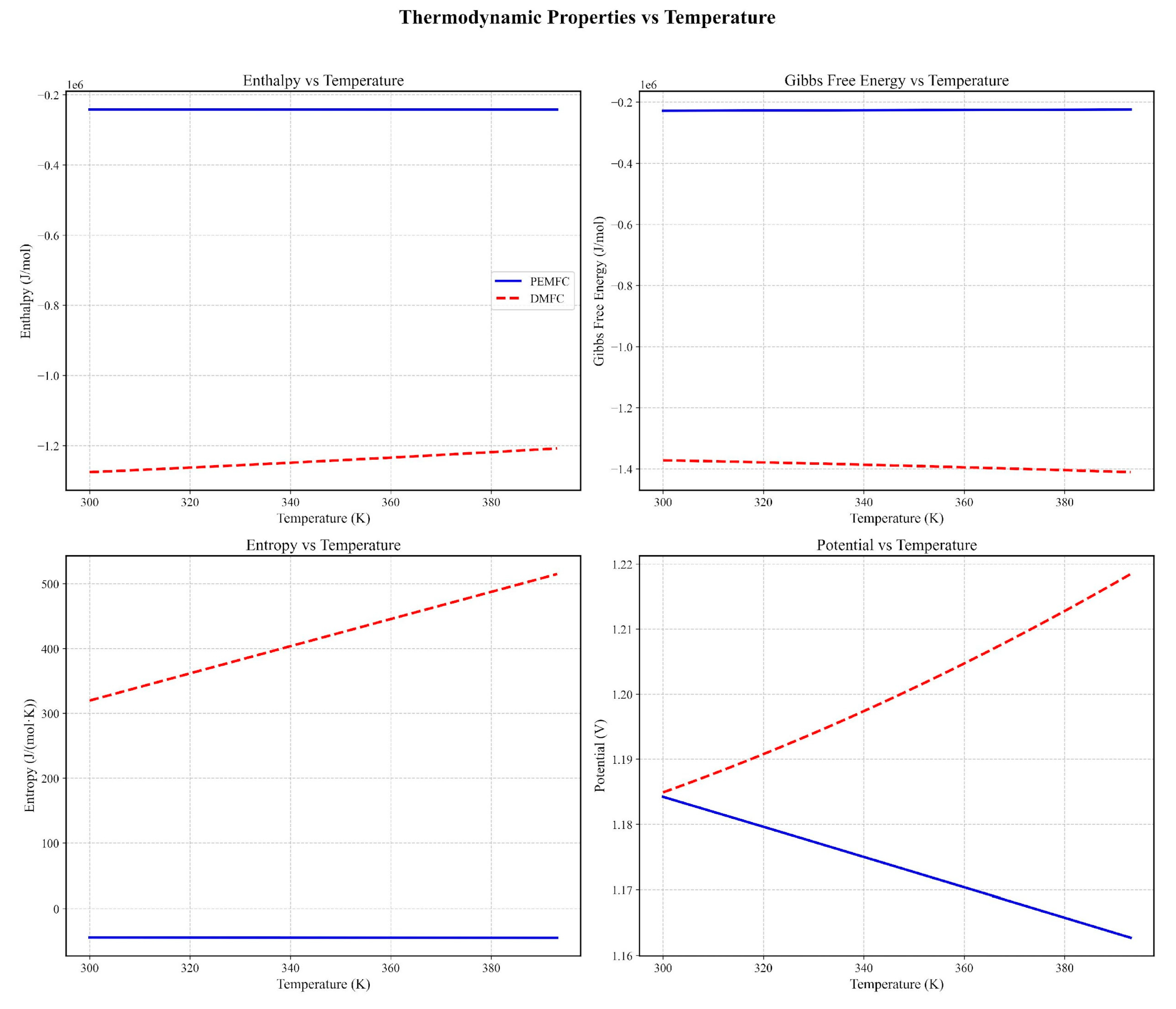
Figure 2.
Theoretical potential of PEM fuel cells and Direct methanol in both escenaries.
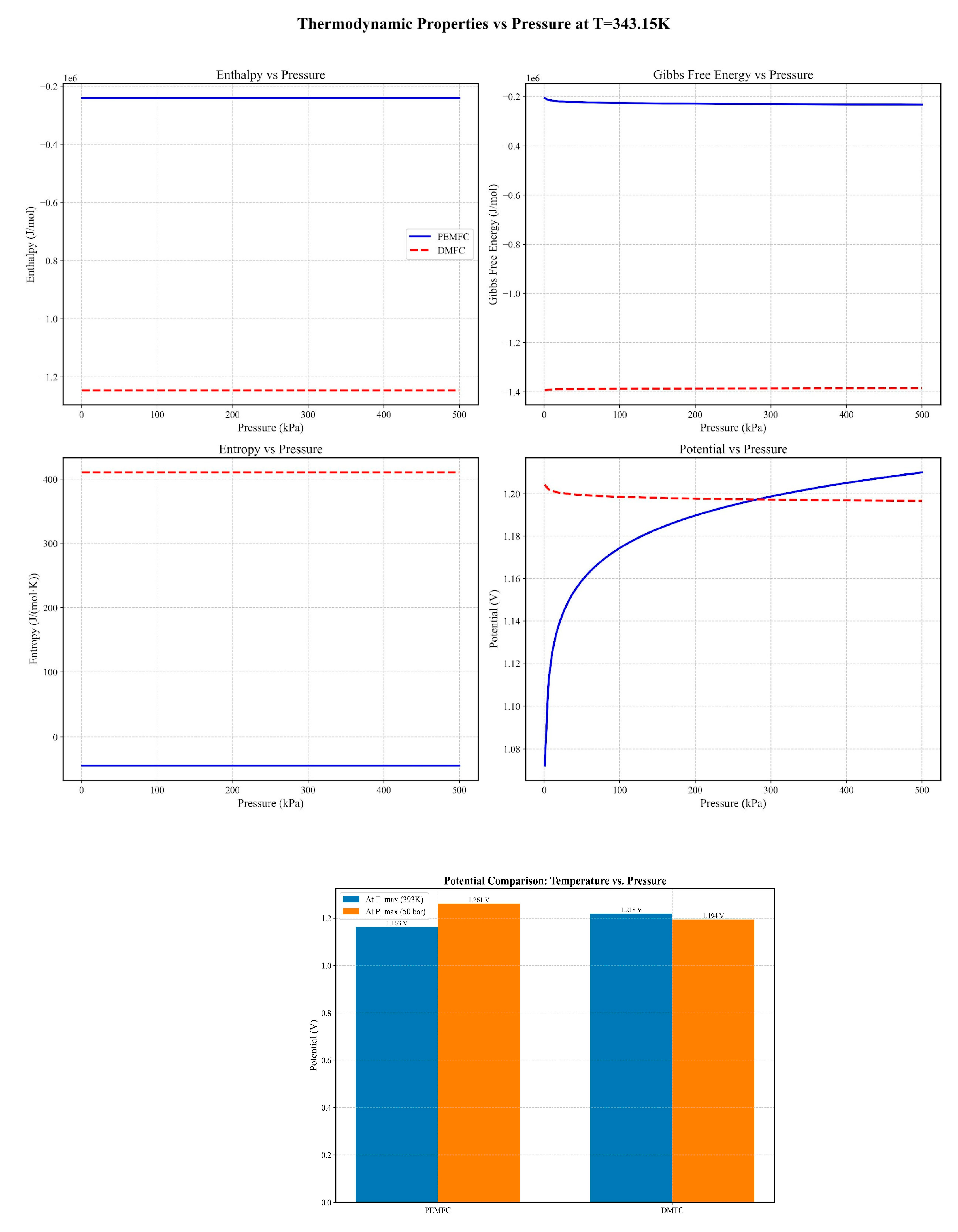
Figure 3.
Principal effects of Temperature and pressure of fuel cells over potential and activation current at cathode: Red line (DMFC), Black line (PEM Fuel cell).
Figure 3.
Principal effects of Temperature and pressure of fuel cells over potential and activation current at cathode: Red line (DMFC), Black line (PEM Fuel cell).
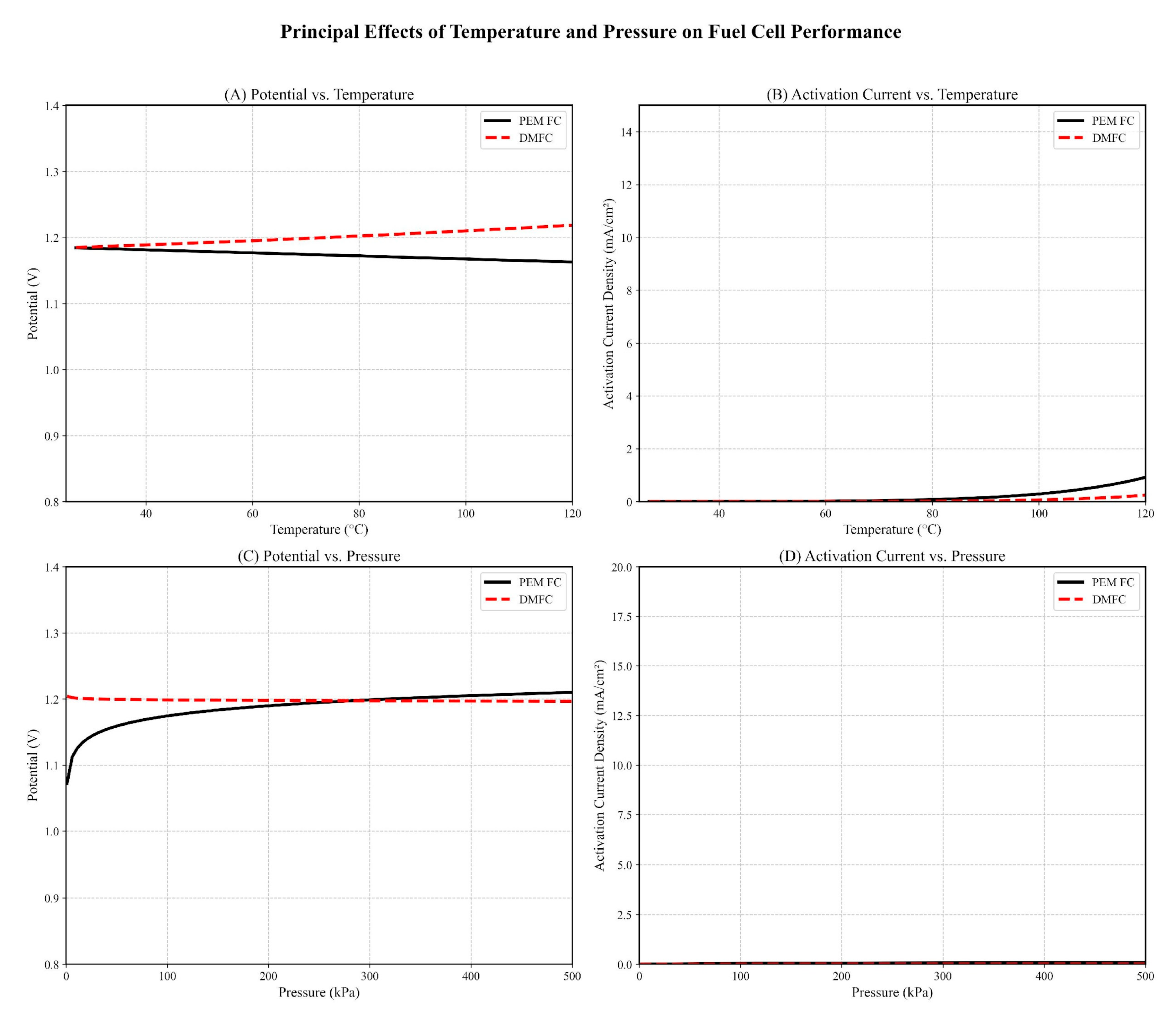
Figure 4.
Power produced in a single PEM (Black line) and DMFC (Red line) fuel cell varying operating current at the cathode.
Figure 4.
Power produced in a single PEM (Black line) and DMFC (Red line) fuel cell varying operating current at the cathode.
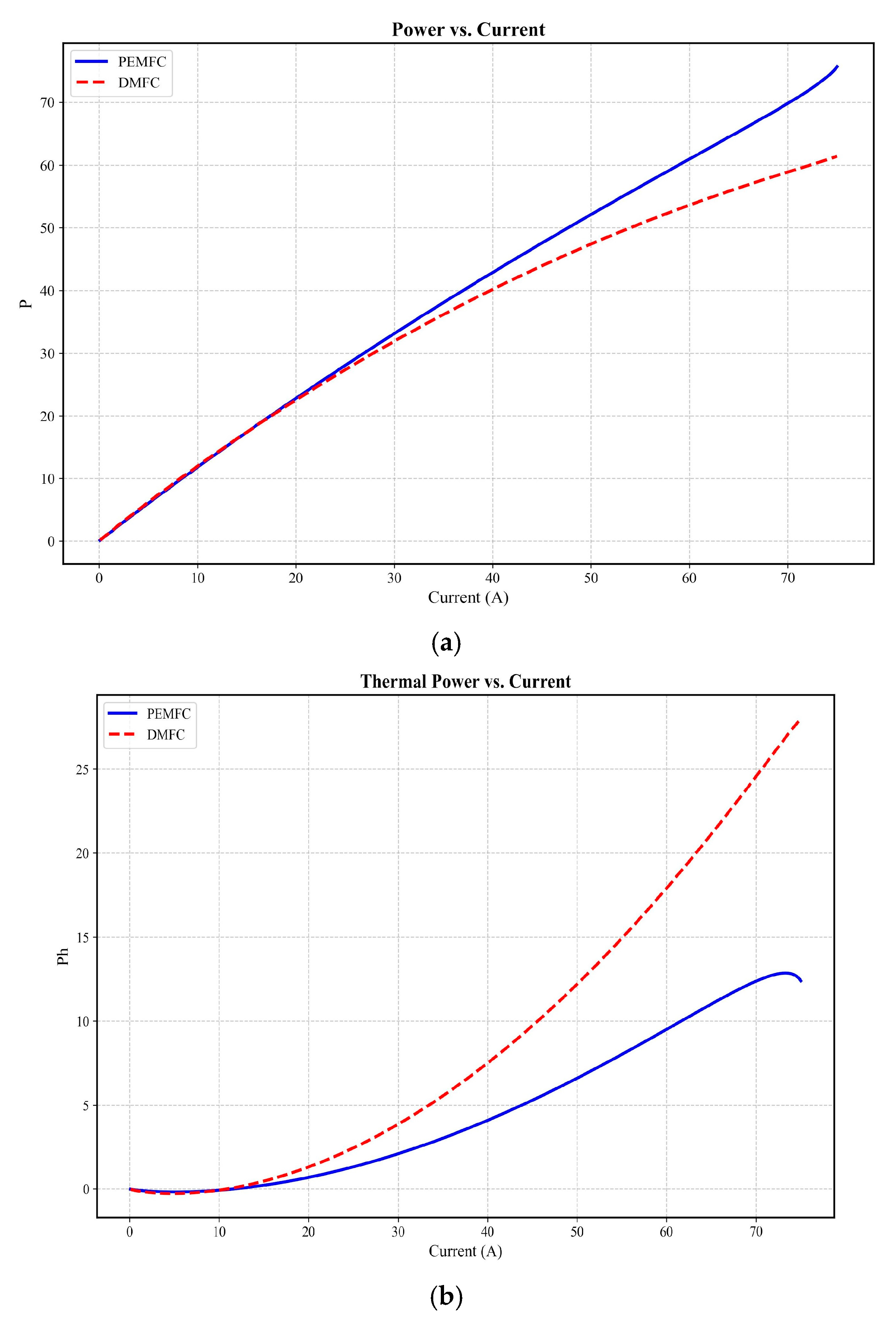
Figure 7.
Temperature and velocity profiles for a single hydrogen-operated fuel cell are depicted in Figure 7. Panels (a) and (b) illustrate conditions at 100°C under 10 Bar.
Figure 7.
Temperature and velocity profiles for a single hydrogen-operated fuel cell are depicted in Figure 7. Panels (a) and (b) illustrate conditions at 100°C under 10 Bar.
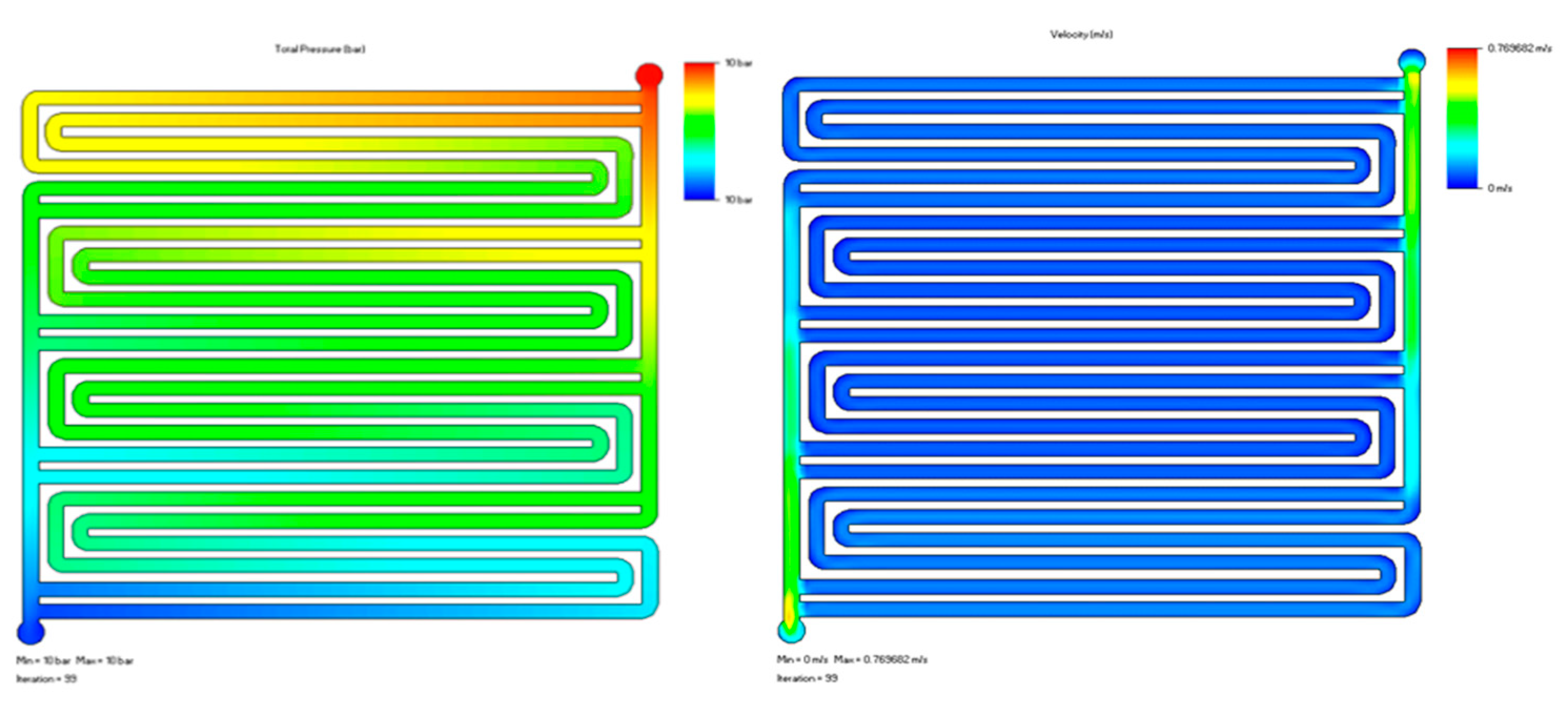
Figure 8.
Dynamic response of temperature of fuel cell at 10 bars for 50 and 100 °C.
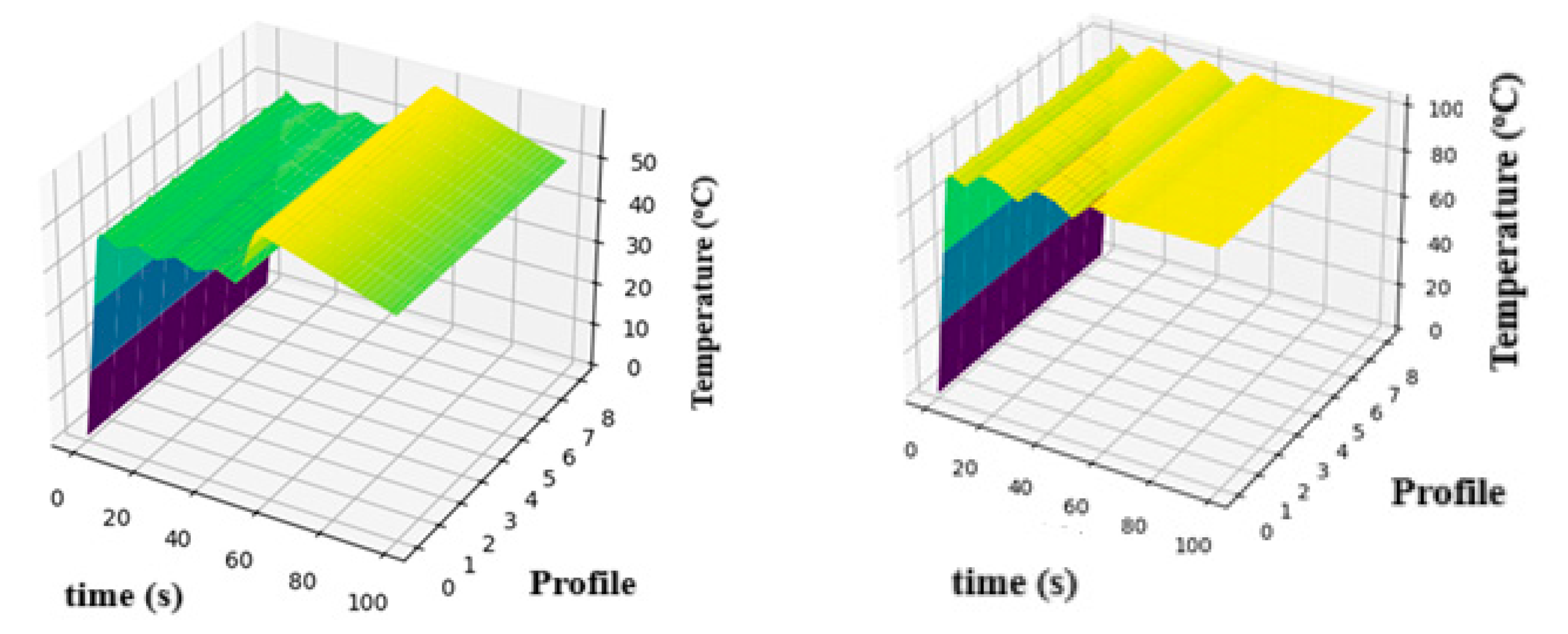
Table 2.
Summary of Key Parameters and Assumptions.
| Parameter | Description | Value/Range |
|---|---|---|
| Operating Temperature | PEMFC & DMFC | 65–100°C |
| Operating Pressure | PEMFC & DMFC | 25–35 bar |
| Reference Pressure (P₀) | - | 1 bar |
| Faraday Constant (F) | - | 96,485 C/mol |
| Gas Constant (R) | - | 8.314 J/(mol·K) |
| Number of Electrons (n) | PEMFC | 2 |
| DMFC | 6 | |
| Current Density (J) | From Tafel equation | Calculated |
| Operating Temperature | PEMFC & DMFC | 65–100°C |
| Operating Pressure | PEMFC & DMFC | 25–35 bar |
| Reference Pressure (P₀) | - | 1 bar |
| Faraday Constant (F) | - | 96,485 C/mol |
| Gas Constant (R) | - | 8.314 J/(mol·K) |
| Number of Electrons (n) | PEMFC | 2 |
| DMFC | 6 | |
| Active Area (A_Active) | Based on current and J | Calculated |
| Simulation Tool | Geometry design | SolidWorks Flow Simulation |
| Meshing & Post-processing | Python with Matplotlib | |
| Faraday Constant (F) | - | 96,485 C/mol |
| Gas Constant (R) | - | 8.314 J/(mol·K) |
| Number of Electrons (n) | PEMFC | 2 |
| Gas Constant (R) | - | 8.314 J/(mol·K) |
| DMFC | 6 | |
| Active Area (A_Active) | Based on current and J | Calculated |
| Simulation Tool | Geometry design | SolidWorks Flow Simulation |
| Meshing & Post-processing | Python with Matplotlib |
Disclaimer/Publisher’s Note: The statements, opinions and data contained in all publications are solely those of the individual author(s) and contributor(s) and not of MDPI and/or the editor(s). MDPI and/or the editor(s) disclaim responsibility for any injury to people or property resulting from any ideas, methods, instructions or products referred to in the content. |
© 2025 by the authors. Licensee MDPI, Basel, Switzerland. This article is an open access article distributed under the terms and conditions of the Creative Commons Attribution (CC BY) license (http://creativecommons.org/licenses/by/4.0/).
Copyright: This open access article is published under a Creative Commons CC BY 4.0 license, which permit the free download, distribution, and reuse, provided that the author and preprint are cited in any reuse.


