

Submitted:
16 June 2025
Posted:
17 June 2025
You are already at the latest version
Abstract
The quality of machined marine propellers plays a critical role in underwater propulsion performance. Precision casting is the predominant manufacturing technique; however, deformation of wax models and rough blanks during manufacturing frequently cause deviations in the dimensions of final products and thus affect propellers’ performance and service life. Current inspection methods primarily involve using coordinate measuring machines and sampling. This approach is time-consuming, has high labor costs, and cannot monitor manufacturing quality in real time. This study developed a real-time online automated measurement system containing a high-resolution CITIZEN displacement sensor, a four-degree-of-freedom measurement platform, and programmable logic controller–based motion control technology to enable rapid, automated measurement of blade deformation across the wax model, rough blank, and final product processing stages. The measurement data are transmitted in real time to a cloud database. Tests conducted on a standardized platform and real propeller blades confirmed that the system consistently achieved measurement accuracy to the second decimal place under the continual measurement mode. The system also demonstrated excellent repeatability and stability. Furthermore, the continuous measurement mode outperformed the single-point measurement mode. Overall, the developed system effectively reduces labor requirements, shortens measurement times, and enables real-time monitoring of process variation. These capabilities underscore its strong potential for application in the smart manufacturing and quality control of marine propellers.
Keywords:
automated inspection system
; cloud database
; data acquisition
; propeller measurement
; real-time online measurement
1. Introduction
Marine propeller blades have highly complex and variable curved surface geometries, and constructing accurate computer-aided design (CAD) models directly from physical prototypes is challenging. Moreover, machined blades often deviate considerably from their original CAD designs, and this machining variation can directly affect propulsion efficiency and service life. Therefore, enhancing the capability and efficiency of blade inspection is essential for substantially improving product quality and performance.
In inspections of propeller blades, the focus is on critical areas such as the leading edge, trailing edge, suction surface, and pressure surface. Because of the sharp curvature at the leading and trailing edges and the relatively thin profile of blades, issues such as twisting and poor bonding with the hub are common. By contrast, the suction and pressure surfaces are relatively flat. To ensure structural accuracy and performance stability, the three-dimensional surface model of a blade must be precisely measured and reconstructed.
Furthermore, minor surface deviations or defects on propeller blades can trigger inertial cavitation during high-speed rotation, which can reduce propulsion efficiency and damage the blades’ surfaces. Accordingly, high-precision and high-efficiency measurement technology needs to be developed to ensure the quality of marine propellers.
Because of the twisted and intricate geometry of marine propellers, the design, machining, and performance analysis of their blades is difficult [2,3]. To achieve precise surface geometry and high propulsion performance, blades are typically manufactured using precision casting techniques, particularly the lost-wax casting process. However, during the drying and cooling phases of this process, the wax models are prone to deformation, which can cause substantial geometric deviations between the final cast components and original CAD models. Casting-induced deformation not only complicates subsequent geometric inspection but also hinders the development of effective machining compensation strategies [4], thereby compromising overall manufacturing accuracy and the operational performance of propellers.
Examining the geometric deviations generated in conventional manufacturing, Njaastad et al. [5] proposed the use of three-dimensional scanning technology to generate point cloud data, which were then employed for manufacturing quality feedback, and the construction of digital twins. Their method provides a quantifiable basis on which deviations can be corrected in the design and manufacturing processes.
In their study, a 3D scanner was employed to acquire point cloud data from propeller blades. The data were then processed using Voronoi partitioning and Delaunay triangulation algorithms to reconstruct the geometric features of the blades’ cross sections, including key parameters such as the camber line, chord length, location of maximum thickness, and skew angle. Found to have both strong versatility and a high degree of potential for automation, this approach complies with the geometric tolerance standards specified in ISO 484 and is applicable to complex blade geometries with high skew angles and large chord length variation.
Marine propellers are the core component of underwater propulsion systems, their geometric configuration and material properties exert decisive influences on propulsion efficiency and cavitation resistance. Bellala et al. [1] noted that conventional manual machining processes are insufficient to meet the current stringent requirements of high precision and high manufacturing consistency. Consequently, the industry is increasingly adopting computer numerical control (CNC) techniques. These techniques offer high repeatability and machining accuracy, greatly reduce the need for manual refinement, and enhance both manufacturing efficiency and quality stability.
The ISO 484 standard clearly defines the manufacturing tolerance grades for marine propellers and thus facilitates quality control with respect to geometric accuracy and consistency. Adhering to the standard ensures high overall reliability and performance in the manufacturing process.
Regarding the efficiency of CNC machining, another study classified propeller blade surfaces into elliptical and hyperbolic regions on the basis of curvature characteristics. Machining deviations and efficiency were further analyzed using ball-end and flat-end milling tools. The method was demonstrated to effectively support tool selection and optimization of machining paths, thereby improving both the quality and productivity of complex blade surface machining [6].
The vibrational behavior of propellers during underwater operation exerts a notable effect on their service life and performance. To address this issue, Abbas et al. [7] proposed a noncontact vibration measurement technique based on a laser Doppler vibrometer. This technique enables the acquisition of accurate vibration responses under both fixed and tracking operation modes without interfering with blade motion. The scholars also compared the measured results with those generated from finite element simulations, and the findings confirmed the high accuracy and practical applicability of the technique in both air and water environments.
The process of casting marine propellers often results in nonuniform deformation at the edges of the propeller blades. Conventional manual finishing methods are time-consuming and not conducive to consistent machining accuracy. To resolve this problem, Cao and Liu [8] proposed an innovative two-stage proximity machining approach. This method leverages the ability of cylindrical cutters to maintain line contact with curved surfaces, meaning that the entire surface of a propeller can be machined in a single-clamp setup. It is particularly suitable for propellers with large projected surface areas, greatly enhancing machining efficiency and surface quality.
Kuo and Dzan [9] applied the first and second fundamental forms in combination with mathematical surface models to conduct in-depth geometric analyses of propeller surfaces. Their investigation into key geometric properties—including the normal curvature, principal curvature, and first and second principal directions—provides a crucial theoretical foundation for programming CNC machining paths in propeller manufacturing.
Lee et al. [10] developed a cost-effective precision caliper system designed for measuring the surface contours of outboard marine engine propeller blades. The system has a simple structural design and clear operating principles. Through practical testing and error verification, this system was demonstrated to have stable and accurate measurement capability.
Cheng et al. [11] further developed an automated grinding system that integrates laser vision with robotic compensation technologies. This system utilizes feature-based point cloud modeling and compensation algorithms to automatically plan grinding paths and dynamically adjust blade edge thickness. The approach greatly enhances machining consistency and efficiency. Post-grinding results showed that the dimensional standard deviation was maintained within the range of 0.04–0.08 mm. Therefore, the system meets precision tolerance requirements and has strong applicability and automation potential.
For high-speed underwater propulsion devices, cavitation not only causes structural damage but also substantially reduces propulsion efficiency. To address this issue, Lu et al. [12] proposed an inverse design process that combines the constraint regions method, Kriging surrogate modeling, and the multiobjective particle swarm optimization algorithm. Their method has three optimization objectives: blade thrust, energy consumption, and the maximum size of cavitation cavities. The optimized system achieved a 6.6% increase in thrust, a 3.1% reduction in power consumption, and a 2.67% decrease in the maximum cavitation cavity size. These results demonstrate the method’s strong potential for the design of high-efficiency propellers.
Khaleed et al. [13] examined the feasibility and performance of additive manufacturing techniques and conventional manufacturing processes for the fabrication of underwater propeller blades. Various materials were tested and analyzed in their study. The findings indicated that although additive manufacturing remains limited in terms of the mechanical strength of its products, it excels in environmental resistance, manufacturing flexibility, and the ability to accommodate structural complexity. In particular, acrylonitrile butadiene styrene materials were demonstrated to have excellent corrosion resistance and molding efficiency, highlighting their potential to replace the metallic materials conventionally used in propeller manufacturing.
In addition, Oliveira et al. [14] proposed a multiobjective optimization method for propeller design to overcome the limitations associated with reliance on commercially available standard models. With the rapid advancement of 3D printing and CNC technologies, designers are increasingly creating customized and high-performance propellers. The study aimed to establish a viable alternative design framework that enables designers to effectively identify the optimal propeller configurations by balancing multiple performance criteria, thereby promoting design innovation and manufacturing flexibility.
From the initial wax injection to final surface finishing, the process used to cast a propeller typically involves 13 distinct stages. Throughout these stages, external mechanical stresses and temperature fluctuations can cause substantial dimensional and accuracy deviations in the cast components. These issues can be mitigated by improving the mold design concepts to reduce the effect of shrinkage. During the drying stage of lost-wax casting, deformation is likely to occur because the structure of the propeller blades is unsupported in the wax model. Thorough inspection of wax model deformation during manufacturing and the removal of components that exceed acceptable deformation thresholds help reduce the failure rate, thus enhancing the overall stability of propeller production.
Currently, coordinate-measuring machines are used to verify whether the geometric features of propeller blades—such as their angle, diameter, and thickness—meet design specifications. However, because of the time-consuming nature of this inspection process and the high labor demand, only sampling inspections are feasible. For the handling of freeform surfaces and large-scale components, these methods are inefficient and difficult to automate. Therefore, a rapid inspection system is urgently needed to improve the inspection efficiency and overall product quality. In the present study, a system was proposed in which dimensions are measured at the wax model, rough blank, and final product stages of propeller manufacturing. The proposed manufacturing process has the following additional steps: Step 5: Wax Pattern Measurement; Step 9: Raw Casting Measurement; and Step 16: Product Measurement. The steps are included in Figure 1, which depicts the overall process flow for precision casting of propellers.
With the acceleration of smart manufacturing and digital transformation, conventional propeller producers are facing increasing challenges in achieving precision, efficiency, and quality consistency. Therefore, the integration of automated measurement and monitoring technologies to enhance process controllability and real-time feedback has become a central focus of recent research.
Cheng and Lin [15] developed a reconfigurable five-axis machining system based on the OPEN CNC architecture. The core structure of this system is a three-degree-of-freedom parallel mechanism combined with an xy platform. Through a custom postprocessing module developed in LabVIEW, the five-axis tool paths generated with CAM software are converted using inverse kinematics, thereby enabling precise tool alignment and machining along each axis. This system supports remachining and can be used for experiments involving the surface machining and calibration of machining points. Its machining precision has been validated through a concave circle engraving test on wax material, confirming its potential for future applications involving automated reworking and finishing of complex surfaces by using 3D scan data.
Because of the complex three-dimensional curvature and geometry of propeller blades, challenges are often encountered during the machining process, such as sudden fluctuations in cutting forces and low machining stability. To address these issues, Cheng et al. [16] developed a cutting-force-estimation system based on current sensing. By integrating a low-cost sensor module (e.g., PZEM-004T) with LabVIEW, the system enables real-time monitoring of electrical current during robotic cutting operations, and its output was validated to be strongly correlated with actual cutting forces.
Cheng et al. conducted experiments using a five-axis platform and implemented robotic machining of propeller prototypes made from polylactic acid (PLA). They successfully obtained the trends indicating how the current varied with the cutting depth and feed rate. For instance, an increase in cutting force generally corresponds with a synchronous rise in motor current. Changes in the contact area could be inferred, and machining condition suitability could be assessed. Overall, the system proposed by Cheng et al. (2024) is a cost-effective and practical alternative to expensive six-axis force sensors for real-time force estimation and thus contributes to the development of real-time monitoring modules for intelligent robotic machining in the future.
The complex three-dimensional geometry of propeller blades also poses numerous challenges in terms of the design of inspection equipment. Such equipment must be capable of high precision, high repeatability, multidirectional measurement, automatic control, data collection and analysis, safety, and ease of maintenance. To meet these requirements, the present study incorporated ball screw linear stages, servo motors, flange-type planetary reducers, coaxial planetary reducers, and an integrated programmable logic controller (PLC) with a human–machine interface (HMI). These components are adopted in coordination with a CITIZEN displacement sensor.
In addition, mechanical probes are used as the primary measurement tool because of their high precision, fast response, reliability, broad applicability, and ease of implementation. Of the various practices currently employed, mechanical probes are those most commonly used for automatic tool center positioning [17,18]. The feedback information provided by these probes can be used to adjust the motion of robotic arms and accurately locate the tool.
In large-scale production environments, measurement efficiency can be improved using an online network for the storage, transmission, and analysis of inspection data. This approach effectively reduces the burden of manual data processing and, when integrated with a cloud-based automated system, enables real-time monitoring and immediate optimization.
2. Experimental Setup
Typically, the spatial position of a point on a propeller, relative to its central axis, is defined by the coordinates Xn, Yn, and Zn. However, accurate surface measurement also requires the determination of the surface normal vector at that point, expressed as Afan and Betan. Consequently, a mechanism with five degrees of freedom is necessary to perform fundamental measurements. Given that a propeller comprises three or more blades, this study adopted a measurement system designed with four degrees of freedom: two linear axes and two rotational axes. The linear axis in the x-direction and the rotational axis in the z-direction are designed with offset values to optimize measurement performance.
Overall, the developed automatic measurement system has two main components: a measurement platform and a power control unit. The measurement platform can be positioned separately in a convenient operational area, and the power control unit can be independently installed in a control cabinet. The system is equipped with two linear axes and two rotational axes, with each rotational axis connected to a planetary reducer.
Specifically, the linear axis in the x-direction, which is responsible for supporting the test object, uses a TECO ETH13 model screw drive with a 5-mm lead. Mounted on this linear axis is a rotational axis in the z-direction, driven by a 1:18 flange-type planetary reducer. The measurement axis comprises a rotational axis in the x-direction, which is driven by a 1:100 low-backlash, coaxial planetary reducer to allow for fine-tuned angular control. The measurement axis is mounted on a cantilever structure that uses a HIWIN KK50 ball screw linear stage. A 90° open fixture is installed on this stage to secure the CITIZEN displacement sensor used for measurement.
A K-type bracket is installed on the measurement platform to elevate the measurement axis, ensuring that the center of the measurement rotation axis is positioned 235 mm above the surface of the three-jaw chuck table. The three-jaw chuck table is fixed on a linear guide in the x-direction. The center of the chuck table is 59-mm offset from the center of the measurement axis along the y-axis, and the displacement between the sensor’s measuring terminal and the x-axis is 204 mm, as illustrated in Figure 2.
The CITIZEN SA-S110 displacement sensor is a high-precision device with a resolution of 0.1 μm and offers absolute coordinate measurement. The sensor housing is manufactured through die casting, and the measurement probe features a 3.175-mm-diameter ceramic ball. The probe shaft is supported by a linear bearing, which enhances durability and reduces the likelihood of erroneous readings. Communication with the DVP28SV11T2 PLC is facilitated through the RS-485 standard.
DVP28SV11T2 is equipped with four high-speed counters and supports four-axis 200-kHz high-speed pulse output. The PLC is compatible with various motion control instructions, including absolute position control and relative position control.
DOP-107IV is a 7-inch HMI model from Delta’s DOP-100 series. It is powered by a Cortex-A8 processor and supports communication through Ethernet and serial ports. In the developed system, RS-485 is used for communication with the PLC, and Ethernet is employed to transmit data to a personal computer.

3. Experimental Method
The experimental framework of this study involved mechanical design, software development, and mechanical validation. In the mechanical design phase, the complete measurement system was modeled using Autodesk Inventor software. CAD drawings of the propeller blades examined in this study were provided by the blades’ manufacturer. These drawings were imported into the aforesaid software to simulate operation of the developed system and verify that its mechanism achieves the desired surface measurement conditions. Once this verification was complete, the system hardware was created to implement the measurement mechanism, and the electrical control layout and configuration were then planned. Figure 3 illustrates the overall research process.
The developed system uses a PCL to perform motion control and data processing tasks. The PLC also reads measurement values from the displacement sensor. The system HMI enables the user to quickly configure measurement positions and view real-time readings. The acquired measurement data are transmitted to a personal computer through Ethernet.
The user can directly input desired coordinate positions into the HMI or utilize the teaching mode, which helps the user guide the sensor to the measurement position. In the system design, the measurement points on propeller blades are determined on the basis of the manufacturer’s empirical knowledge, which indicates the regions prone to large deformation during production. These critical points are primarily along the leading and trailing edges and at the blade tips, which are areas particularly susceptible to cracking and warping during the postinjection cooling and drying stages. The developed system requires the following parameters for accurate measurement of manufacturing quality: the x-axis advancement distance of the three-jaw chuck platform, rotational offset angle of the propeller about the chuck platform axis (γ), inclination angle of the measurement axis relative to the x-axis normal vector (α), and vertical advancement of the measurement axis (). The procedure for capturing the spatial coordinates of measurement points is described as follows:
- A working plane perpendicular to the central axis at the measurement point is defined, and a line is drawn through the measurement point and the axis on this working plane. Measuring the length of this line yields the distance between the measurement point and central axis (Figure 4).
- A second working plane perpendicular to the line drawn in Step 1 is defined. On this new plane, a tangent and a normal vector passing through the measurement point are constructed (Figure 5).
- The completed auxiliary-line model of the propeller is positioned in an assembly drawing. The propeller is aligned under the measurement axis, and the axis and propeller are rotated so that the surface normal at the target point aligns with the measurement axis (Figure 6).
Through the measurement and analysis process described above, the spatial coordinates (Ax, Ay, Az) of the three-jaw chuck during measurement from the CAD model can be obtained, as well as the normal inclination angle α and offset angle γ of the measurement point on each propeller blade. Here, γ represents the rotation angle about the z-axis of the chuck platform relative to the zeroed position. The relative coordinates of the probe (Δx, Δy, Δz) and the advancement distance TL along the direction of the measurement axis can be calculated by combining the normal inclination angle α and the difference between the chuck coordinate Ay and probe offset Δy.
Accordingly, the geometric information for multiple measurement points (four in the case of this study) can be successfully established (Figure 7).
In addition to having a graphical construction and teaching mode, the developed system supports inverse kinematics validation by using parametric formulas. The calculated parameters can be input directly to the PLC to provide precise movement instructions for each axis.
When a specific point on a propeller blade, such as point A, is selected as the measurement target, its coordinates (Ax, Ay, Az) can be obtained from the CAD model as a reference relative to the center of the propeller. The radial distance from point A to the propeller center is denoted R, and the height of the probe’s rotational center is Hz. The relative distances between the probe and point A along each axis are Px, Py, and Pz (distances in the x-axis, y-axis, and z-axis directions).
Equations (1)–(5) are used to determine the geometric parameters of each measurement point on a propeller blade. In these equations, T0 denotes the initial length of the probe, and TL represents the actual extension length of the probe during measurement. The parameter α indicates the angle of inclination of the probe relative to the x-axis, γ is the angle of rotation of the blade relative to the z-axis, and ΔY is the offset between the center of the probe and the center of the propeller along the y-axis.
To determine the geometric parameters of measurement point A on a blade, the rotational angle γ of point A with respect to the z-axis can be determined as shown in Figure 8-1 (top view of the propeller machining system). This angle allows for precise calculation of the coordinates Ax and Ay. Subsequently, through referencing of Figure 8-2 (side view showing the xz geometry), Figure 8-3 (front view showing the α-axis rotation), and Figure 8-4 (diagram showing the inclination angle and tangential contact point), a complete blade measurement and positioning model can be systematically established. This model effectively supports applications in automated machining and compensation control.
Ax=R*cos(γ)
Ay= R*sin(γ)
x-axis advancement = Px − Ax
Given that α approximates the surface normal vector at point A,
T0*sin(α)=Ay-ΔY
TL = [(Hz − Az)/cos(α)] − T0
Equations (1)–(5) can be employed again to calculate the geometric parameters for measurement points B, C, and D on the blade.
The PLC controls each axis by issuing high-speed pulse signals to the servo motor controllers, and the displacement sensor transmits measurement data to the PLC through RS-485 communication. The PLC and HMI also communicate through RS-485.
The system developed in this study is operated through an HMI. The PLC’s program structure is illustrated in Figure 9. This system supports several control modes: continuous measurement mode, single-point measurement mode, teaching mode, return-to-origin mode, and fast return-to-origin mode. These control modes can be selected from the main page of the HMI (Figure 10). The measurement mode interface displays three key elements, namely measurement values, current coordinates, and the current mode in use (Figure 11 and Figure 12). In teaching mode, the sensor is moved to the user-designated measurement point, and the current coordinates are recorded to enable subsequent automatic measurements (Figure 13). Alternatively, the user can utilize CAD models to extract the surface normal inclination angle, propeller offset angle, and coordinate offsets of the measurement point and can then input these values to the HMI (Figure 14). These parameters can also be written directly into the internal memory of the PLC for automated operation.
4. Experimental Results
Experiments were performed in which the measurement platform architecture illustrated in Figure 1 was employed to examine the four propeller blade measurement points shown in Figure 7. To explore the effect of measurement mode on measurement accuracy, this study employed the continuous measurement mode and single-point measurement mode. The measurement processes under each mode were recorded and analyzed using the corresponding video documentation (continuous measurement mode video [19] and single-point measurement mode video [20]).
The results obtained under the two measurement modes were compared in terms of accuracy, repeatability, and operational efficiency. The findings served as a critical basis for subsequent system optimization and measurement mode selection.
4.1. Verification and Analysis of Measurement Results
A total of 100 sets of data were collected from a standard platform under the continuous measurement mode. Additionally, 200 sets of data were collected from a marine metal propeller through the continuous measurement mode and single-point measurement mode. Each data set consisted of measurements taken at three points, with four repeated samples per points, yielding a total of 1,200 data points. The 1,200 data points acquired from the standard platform were first analyzed using analysis of variance (ANOVA) to examine between-group differences and determine whether the measurement values were consistent and correlated. In addition, measurement values to the second and third decimal places were extracted and subjected to homogeneity testing to evaluate whether statistically similar characteristics were obtained for the different numbers of decimal places. This analysis was conducted to determine the level of decimal precision that the measurement system could consistently maintain.
Furthermore, the marine metal propeller was evaluated under both the continuous and single-point measurement modes. The one-way ANOVA homogeneity test was conducted to compare values at the second and third decimal places, thereby assessing the reliability of measurements at each precision level. One-way ANOVA was also employed to determine whether these modes had any significant differences or stability patterns.
4.1.1. Precision Analysis of Measurement Values on the Standard Platform
The precision of the developed measurement system was evaluated using the one-way ANOVA homogeneity test applied to data collected from the standard platform. The system was configured to continuously collect 100 sets of data. Each data set comprised measurements at three points, with four repeated measurements per point, yielding a total of 1,200 data points. For this data set, measurement values to the second and third decimal places were divided into four groups on the basis of the four repeated measurements. The homogeneity of variance in the data set was then tested to assess the level of decimal precision the system could reliably achieve. During measurement, the standard platform was placed on the three-jaw chuck table, with the measurement axis aligned perpendicularly to the platform. The axis was lowered until the probe made contact with the platform to collect data.
The results of the homogeneity of variance test revealed a significant difference between the variance of values to the second versus third decimal place (Levene = 1779.26, p < 0.001). Specifically, the variance for values to the second decimal place was 0.213, whereas that for values to the third decimal place was 7.081. This indicates a substantial difference in the variability of values beyond the second decimal, confirming that the developed system achieves stable precision up to the second decimal place (Table 1).
4.1.2. Stability Analysis of Measurement Values on the Standard Platform
To evaluate the stability of the measurement system, one-way ANOVA was applied to measurements from the standard platform. The system was configured to continuously collect 100 sets of data, with each set including measurements at three points and four repeated measurements per points, yielding a total of 1,200 data points. Whether repeated measurements introduced any systematic bias in the measurement results was determined.
The ANOVA results indicated that the developed system made repeated measurements with nonsignificant differences (F = 0.025, p > 0.05), as shown in Table 2. This finding confirms that the system does not introduce bias due to repeated sampling, demonstrating consistent measurement stability.
4.2. Propeller Measurement Results
Following validation of the standard platform, the measurement system was applied to actual marine propeller blades. During the measurement process, the measurement axis was parallel to the surface normal of the target measurement plane. The system was programmed to perform 100 consecutive measurements under both the continuous measurement mode and single-point measurement mode. Each data set comprised measurements at the same points on three propeller blades, with four repeated measurements per point, yielding a total of 1,200 data points. The precision and stability of the two measurement modes were compared. Homogeneity testing was conducted to determine the level of decimal precision reliably achieved, and ANOVA was used to assess whether repeated measurements introduced systematic bias. Finally, the independent-sample t test was conducted to determine whether the two measurement modes differed significantly in terms of measurement accuracy, repeatability, and measurement time. In this manner, the most efficient mode for this measurement platform was identified.
4.2.1. Precision Analysis in Continuous Measurement Mode
The one-way ANOVA homogeneity test revealed that, under the continuous measurement mode, the values measured for the first, second, and third blades were nonsignificantly different to the second decimal place. Thus, the developed system consistently achieves precision up to the second decimal place for all three blades when operated in the continuous measurement mode (Table 3).
4.2.2. Stability in Continuous Measurement Mode
One-way ANOVA was performed to assess the measurement stability of the developed system. The results revealed nonsignificant differences in the repeated measurements for the first, second, and third blades (F = 0.004, p > 0.05; F = 0.090, p > 0.05; and F = 0.027, p > 0.05, respectively). This confirmed that the data collected across the different groups were statistically consistent, reflecting a high level of measurement stability. Therefore, the measurement platform of the developed system does not introduce bias under repeated sampling (Table 4).
4.2.3. Precision Analysis in Single-Point Measurement Mode
The one-way ANOVA homogeneity test was employed to evaluate the measurement precision under the single-point measurement mode. The results revealed nonsignificant differences in the measured values at the second decimal place. However, the variances at the second and third decimal places differed significantly. Thus, the developed system consistently achieves precision up to the second decimal place when being operated in the single-point measurement mode (Table 5).
4.2.4. Stability in Single-Point Measurement Mode
The one-way ANOVA homogeneity test was conducted to assess the measurement stability of the system under the single-point measurement mode. The results revealed nonsignificant differences between repeated measurements for the first, second, and third propeller blades (F = 0.378, p > 0.05; F = 0.394, p > 0.05; and F = 0.575, p > 0.05). These results confirm that the developed system is highly stable and that no observable measurement bias is introduced by repeated sampling (Table 6).
4.3. Comparison of Measurement Accuracy in Two Measurement Modes
Statistical testing revealed a significant difference between the continuous measurement mode and single-point measurement mode. Levene’s test (F = 5.684, p = 0.017) revealed that the variances of the two modes are unequal (Table 7). Accordingly, Welch’s t test, which does not assume equal variances, was used for further analysis. The variance for the continuous measurement mode was 0.868, whereas that for the single-point measurement mode was 0.970, suggesting that the continuous measurement mode exhibited smaller variability and therefore greater stability. This difference may be attributable to the distinct measurement procedures of the two modes. In the single-point measurement mode, the system measures one point and then rotates to the corresponding point on the next blade, which involves more frequent axis movements than does the continuous measurement mode.
Welch’s t test revealed a significant difference in the mean values between the two measurement modes (p < 0.001). The mean difference was determined to be −0.695, which indicates that the average measurement value in the continuous measurement mode is significantly lower than that in the single-point measurement mode. This finding further highlights that the two measurement modes differ in terms of measurement stability and potential errors.
5. Conclusions
This study successfully developed a real-time online automatic measurement system designed specifically for manufacturing marine propeller blades. The system, which has integrated cloud-based data storage and analysis capabilities, is built on a four-degree-of-freedom measurement platform that has two linear axes and two rotational axes. Furthermore, the system combines a high-resolution CITIZEN displacement sensor with a PLC-based motion control mechanism, thereby enabling precise automated measurement at multiple critical locations on propeller blades.
The experimental results confirmed that the system achieves measurement precision up to the second decimal place under both the continuous and single-point measurement modes. Notably, the continuous measurement mode was found to have superior performance in terms of precision, stability, and measurement efficiency, highlighting its advantages for deployment in large-scale manufacturing environments. Validation performed using both the standard platform and real blade measurements indicated that the developed system effectively reduces reliance on manual labor, shortens inspection times, and facilitates early detection of casting or machining-induced deformation, thereby improving the overall efficiency of quality control.
In the future, the present research team will focus on advancing multipoint simultaneous measurement techniques, optimizing sensor placement and system response time, and integrating artificial intelligence–driven data analysis to enhance decision-making support and system self-diagnosis. These developments could facilitate intelligent manufacturing and automated quality management. Moreover, the developed system has the potential to be extended to other freeform surface components, such as fan blades and turbine blades. Overall, it offers a cost-effective and feasible solution for precision surface quality inspection in high-precision machining applications.
Acknowledgments
The authors gratefully acknowledge the financial support provided by National Pingtung University under Research Projects NPTU-AD-114-1-2, NPTU-114-010, and CCS-113-003. This work was also supported by the National Science and Technology Council (NSTC) of Taiwan under Project No. 114-2622-E-153-001. The support from these institutions has been essential to the successful completion of this research.
References
- Bellala, S. M., Prasad, K. S., & Mohan, V. M. (2017). Design and Manufacturing of Marine Propeller. Trends in Machine Design, 4(3), 26-37.
- Kudo, T., Ukon, Y., Kurobe, Y., & Tanibayashi, H. (1989). Measurement of shape of cavity on a model propeller blade. Journal of the Society of Naval Architects of Japan, 1989(166), 93-103. [CrossRef]
- Ukon, Y., Kudo, T., Kurobe, Y., Kamiirisa, H., Yuasa, H., Kubo, H., & Itadani, Y. (1990). Measurement of Pressure Distribution on a Full Scale Propeller Measurement on a Conventional Propeller. Journal of the society of naval architects of Japan, 1990(168), 65-75. [CrossRef]
- Cheng, Y. S. , Shah, S. H., Yen, S. H., Ahmad, A. R., & Lin, C. Y. (2023). Enhancing Robotic-Based Propeller Blade Sharpening Efficiency with a Laser-Vision Sensor and a Force Compliance Mechanism. Sensors, 23(11), 5320. [CrossRef]
- Njaastad, E.B. , Steen, S. & Egeland, O. Identification of the geometric design parameters of propeller blades from 3D scanning. J Mar Sci Technol 27, 887–906 (2022). [CrossRef]
- Kuo, H. C., & Dzan, W. Y. (2002). The analysis of NC machining efficiency for marine propellers. Journal of Materials Processing Technology, 124(3), 389-395. [CrossRef]
- Abbas, S. H. , Jang, J. K., Kim, D. H., & Lee, J. R. (2020). Underwater vibration analysis method for rotating propeller blades using laser Doppler vibrometer. Optics and Lasers in Engineering, 132, Article 106133. [CrossRef]
- Cao, L. , Liu, J. An integrated surface modeling and machining approach for a marine propeller. Int J Adv Manuf Technol 35, 1053–1064 (2008). [CrossRef]
- Kuo, H. C., & Dzan, W. Y. (2002). The analysis of NC machining efficiency for marine propellers. Journal of Materials Processing Technology, 124(3), 389-395. [CrossRef]
- Lee, S. , Lovenitti, P., Lam, M. et al. A Cost-Effective Thickness Measurement Technique for Engine Propellers. Int J Adv Manuf Technol 20, 180–189 (2002). [CrossRef]
- Cheng, Y. S., Yen, S. H., Bedaka, A. K., Shah, S. H., & Lin, C. Y. (2023). Trajectory planning method with grinding compensation strategy for robotic propeller blade sharpening application. Journal of Manufacturing Processes, 86, 294-310. [CrossRef]
- Lu, Y., Guo, Z., Zheng, Z., Wang, W., Wang, H., Zhou, F., & Wang, X. (2023). Underwater propeller turbine blade redesign based on developed inverse design method for energy performance improvement and cavitation suppression. Ocean Engineering, 277, 114315. [CrossRef]
- Khaleed, H. M. T., Badruddin, I. A., Alahmadi, Y. H., Haider, A. A., Tirth, V., Rajhi, A. A., ... & Elshalakany, A. B. (2022). Comparison of 3D printed underwater propeller using polymers and conventionally developed AA6061. Journal of Materials Engineering and Performance, 31(6), 5149-5158. [CrossRef]
- Oliveira, N.L. , Rendón, M.A., Lemonge, A.C.d.C. et al. Multi-objective optimum design of propellers using the blade element theory and evolutionary algorithms. Evol. Intel. 17, 1623–1653 (2024). [CrossRef]
- Cheng, Y. M. , & Lin, M. S. (2020). Development of Reconfigurable Five-axis Machine Tool Using OPEN Computer Numerical Control System Integration Architecture. Sensors & Materials, 32. [CrossRef]
- Cheng, Y. M. , Chang, G. M., & Chang, Y. H. (2024). Application of Motor Current Measurement Technology in Propeller Cutting by Robotic Arms. Sensors & Materials, 36. [CrossRef]
- Yuan-Ming Cheng*, Machining with a Precision Five-Axis Machine Tools Created by Combining a Horizontal Parallel Three-Axis Motion Platform and a Three-Axis Machine Tools, Materials 2022, 15(6), 2268. [CrossRef]
- Yuan-Ming Cheng*, Yu-Hao Chang and Yu-Jie Weng, Automatic Correction of Machining Reference Plane Level to Enhance Machining Quality for Six-axis Robotic Arm, Accepted for publication in Sensors and Material. 2025.02.
- Yuan-Ming Cheng. (2025, June 2). Propeller continuous measurement mode. [Video file]. Available online: https://www.youtube.com/watch?v=5MUp2FtxCzg.
- Yan-Ming Cheng. (2025, ). Propeller single-point measurement mode [Video file]. Available online: https://www.youtube.com/watch?v=kHIJ9kU4vX0&t=2s.
Figure 1.
Process flowchart for the precision casting of marine propellers.
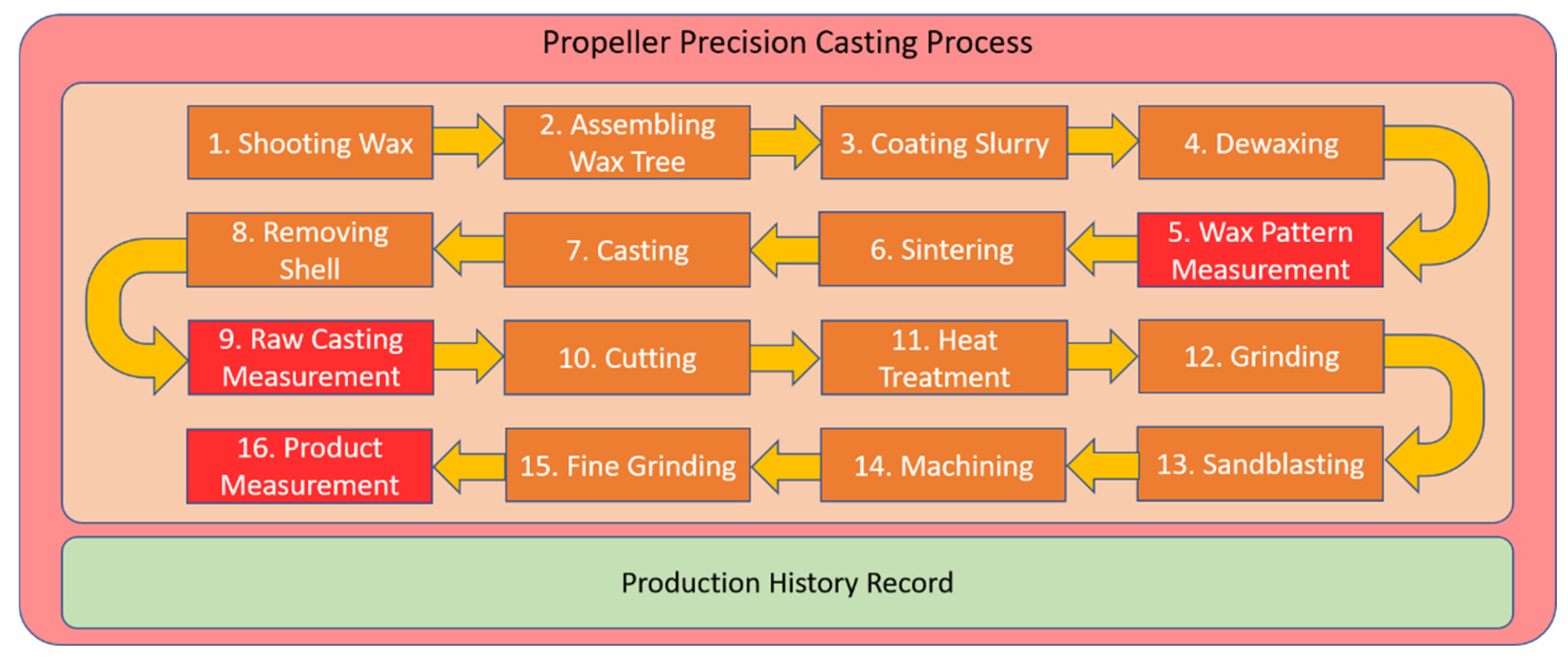
Figure 2.
Schematic of the measurement platform and coordinate axes.
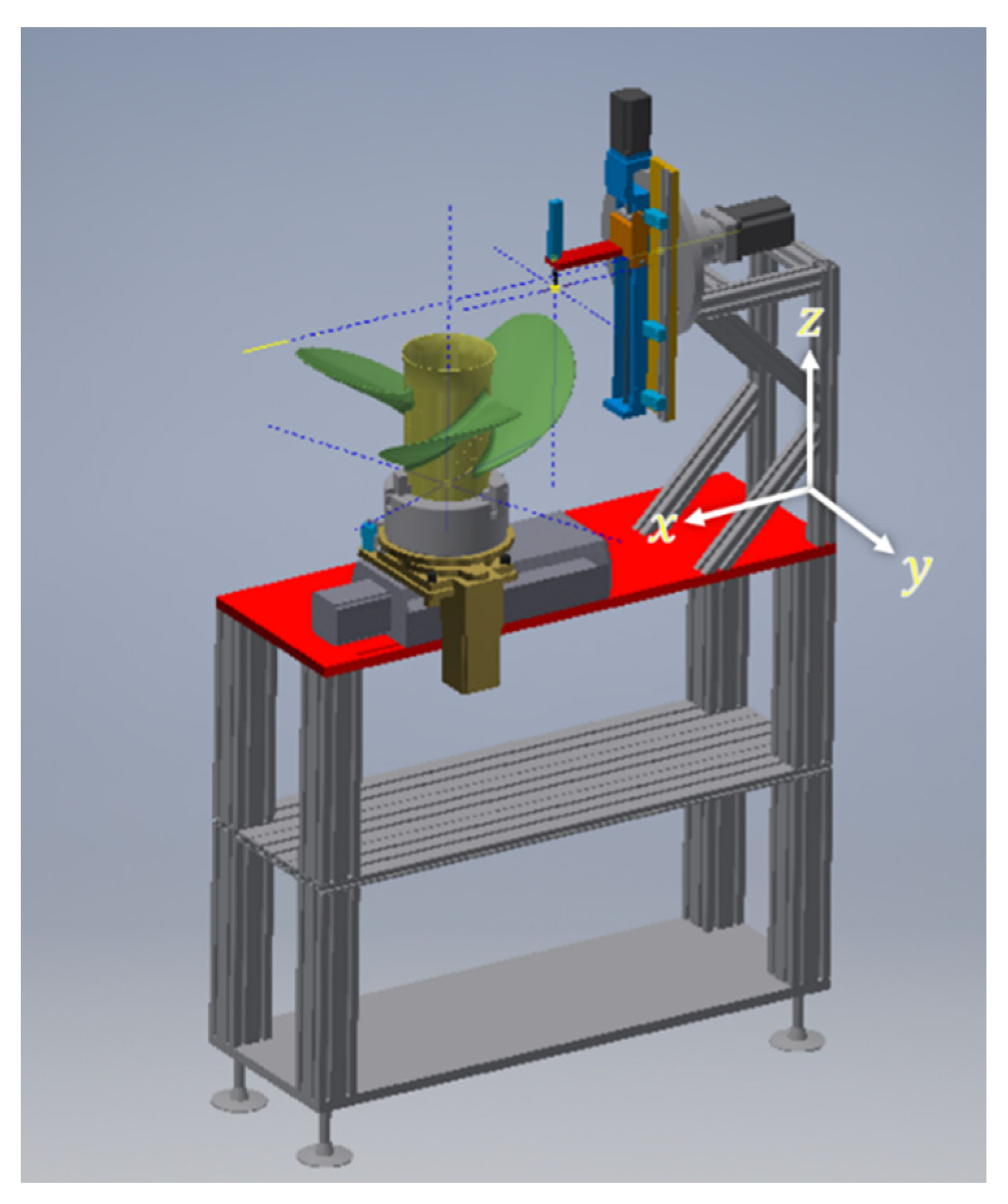
Figure 3.
Research process flowchart.
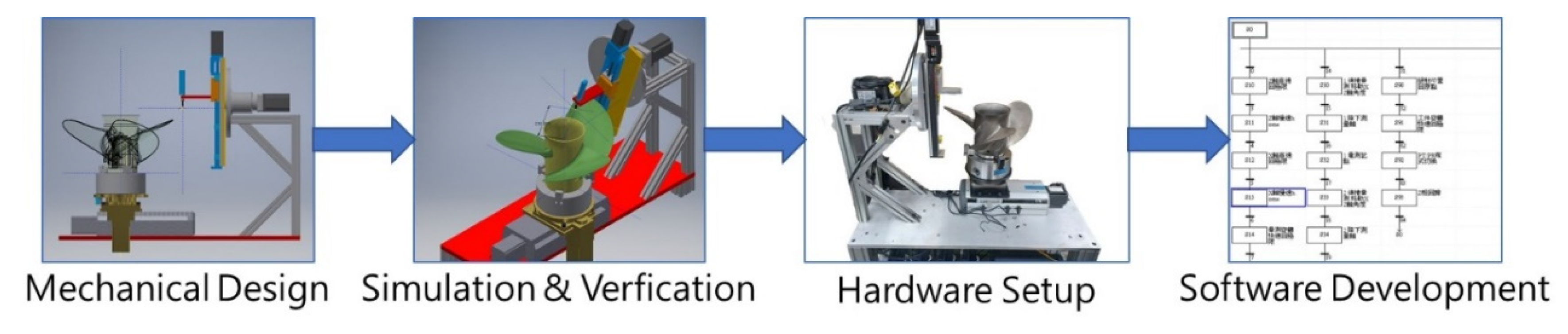
Figure 4.
Configuration of a working plane perpendicular to the central axis.
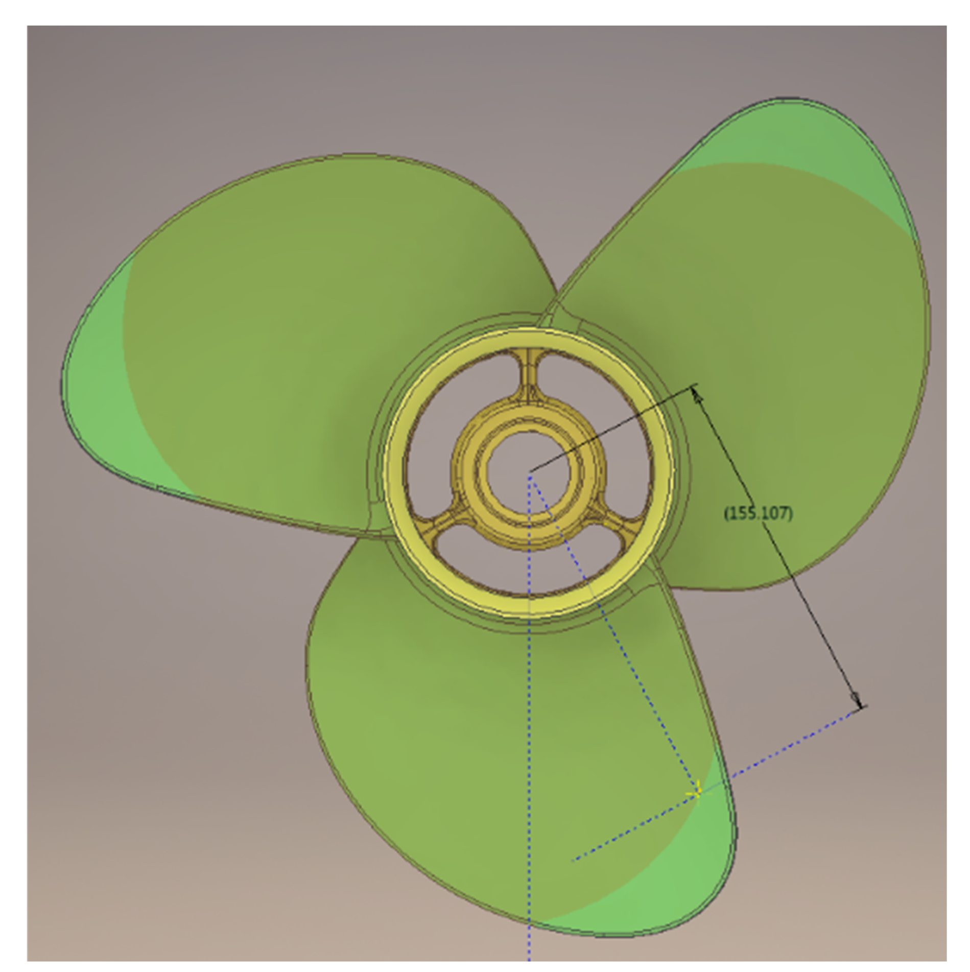
Figure 5.
Construction of the tangential and normal vectors at the measurement points.
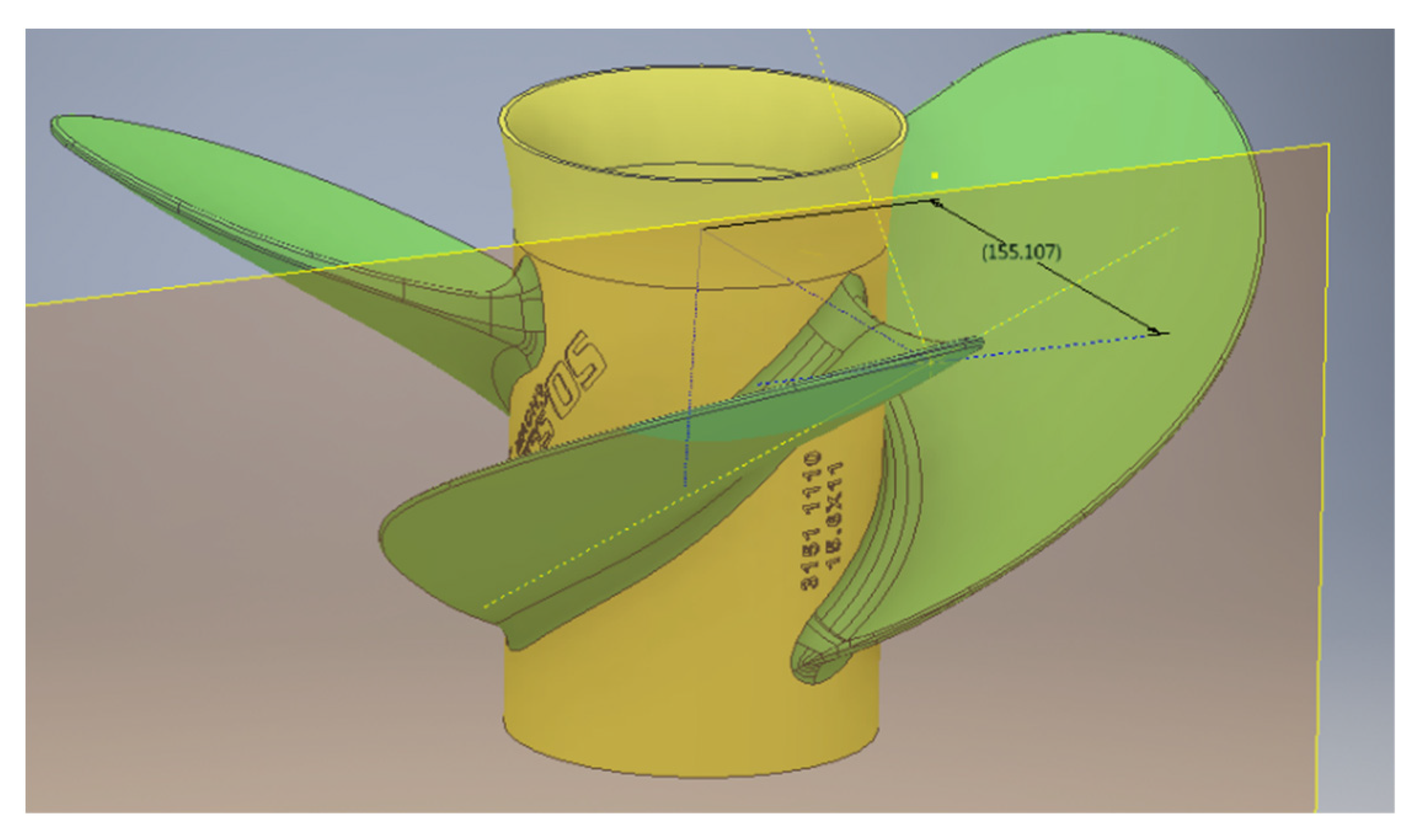
Figure 6.
Alignment of the measurement point with the sensor.
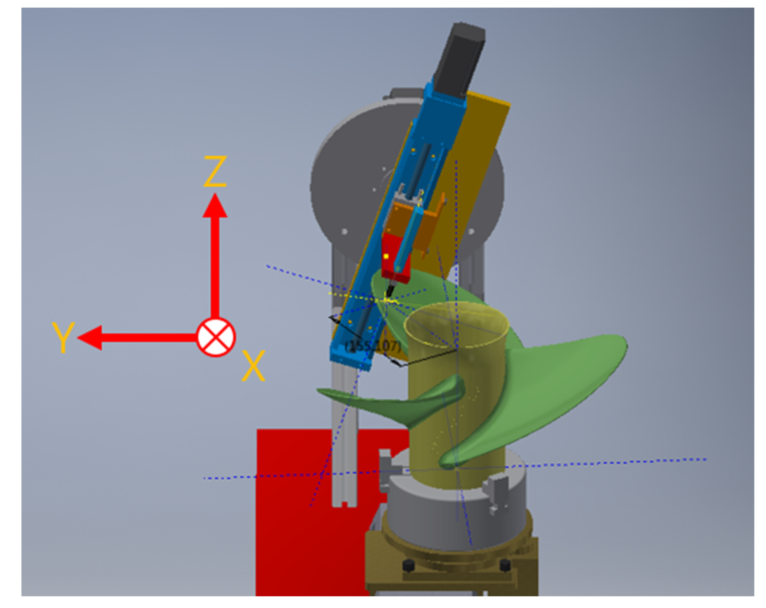
Figure 7.
Measurement Points A, B, C, and D.
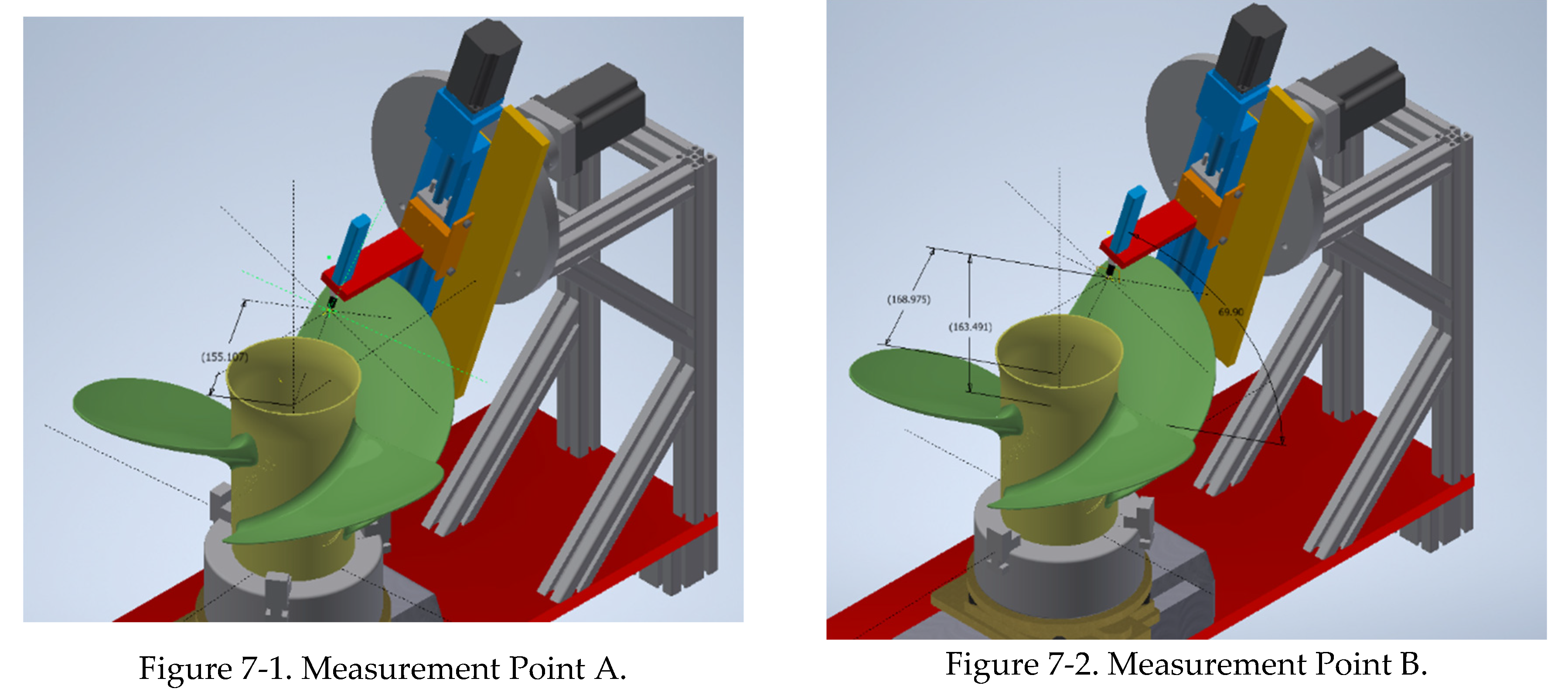
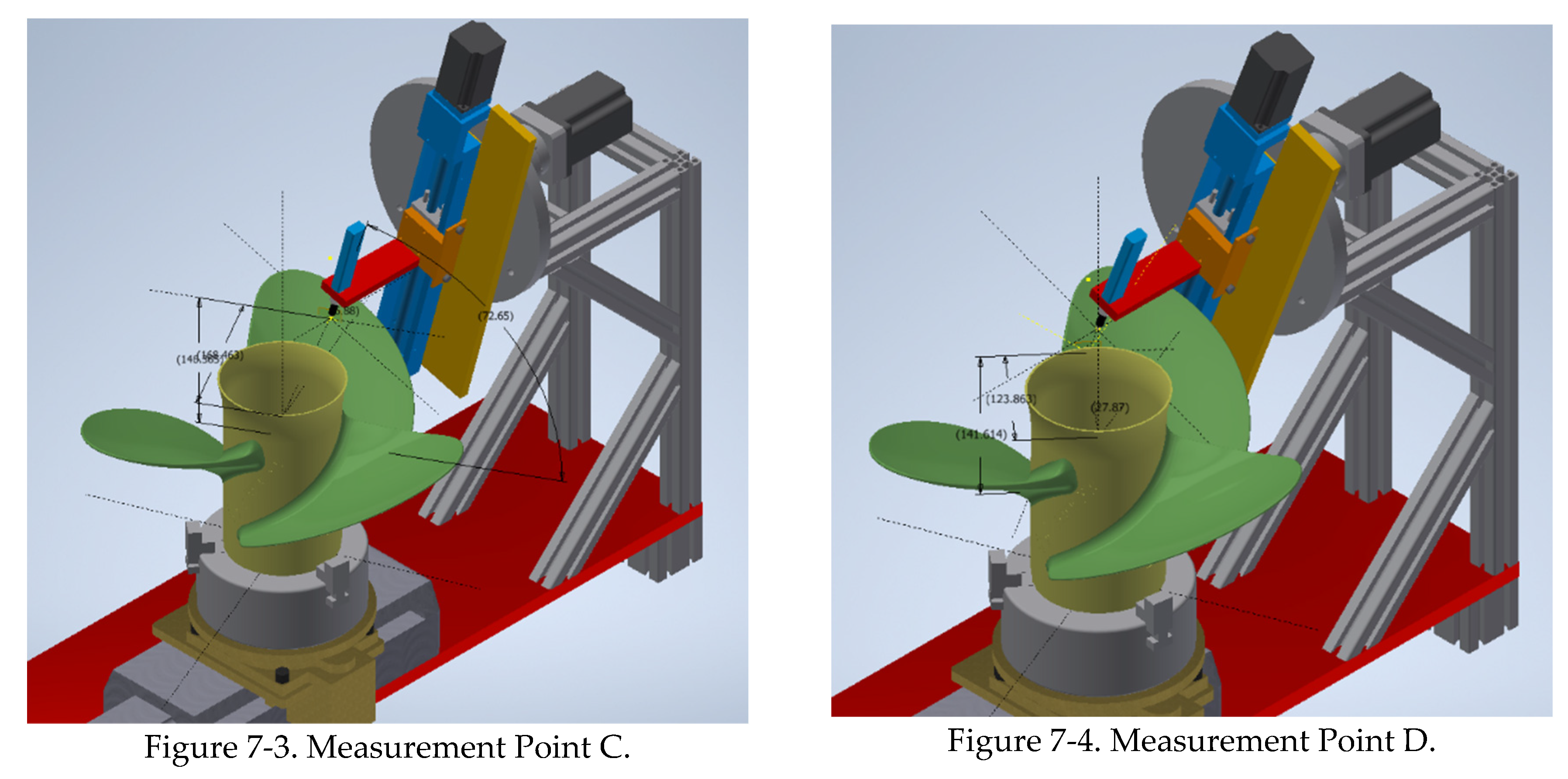
Figure 8.
Composite views of the propeller machining system.
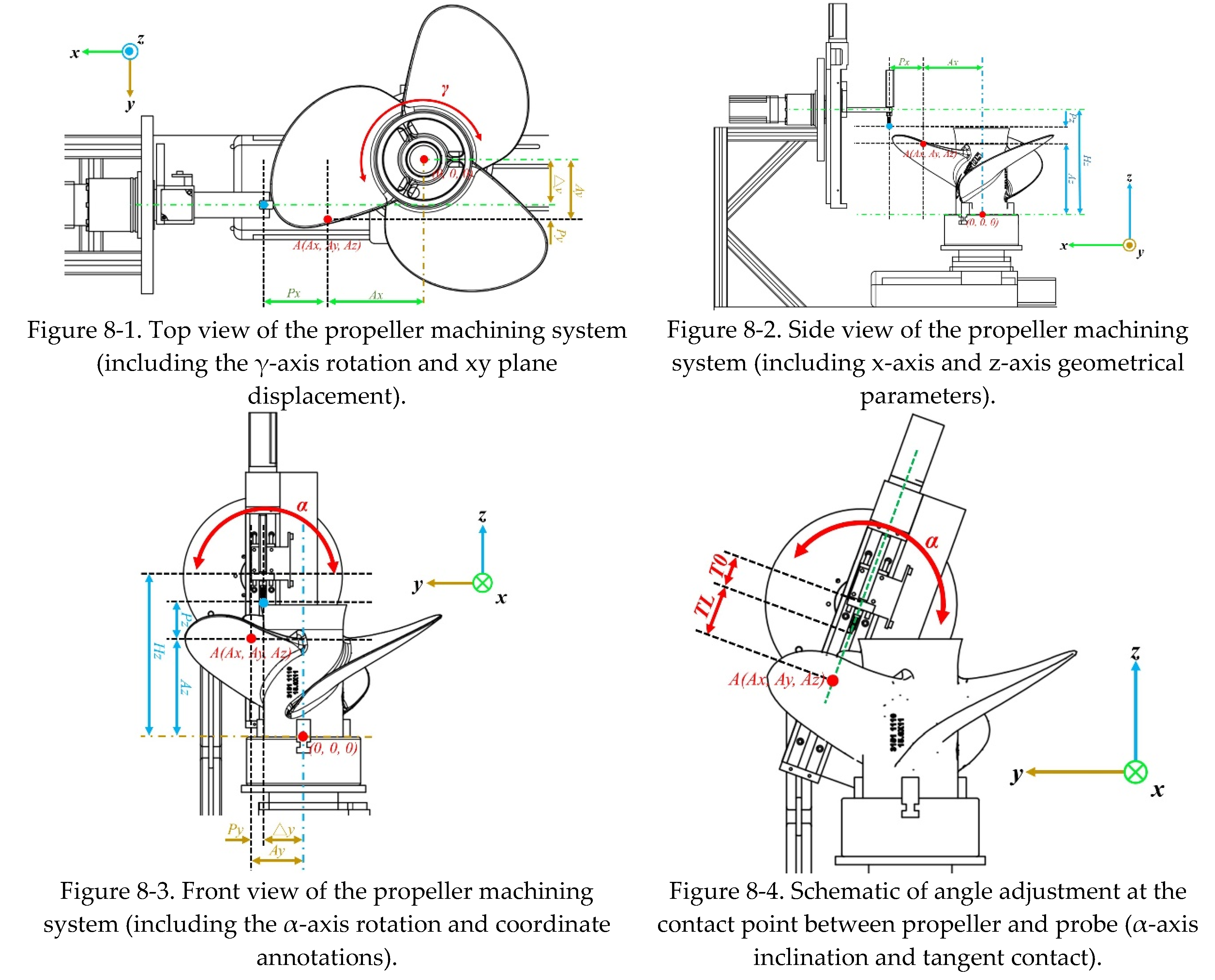
Figure 9.
Program architecture diagram of the PLC.
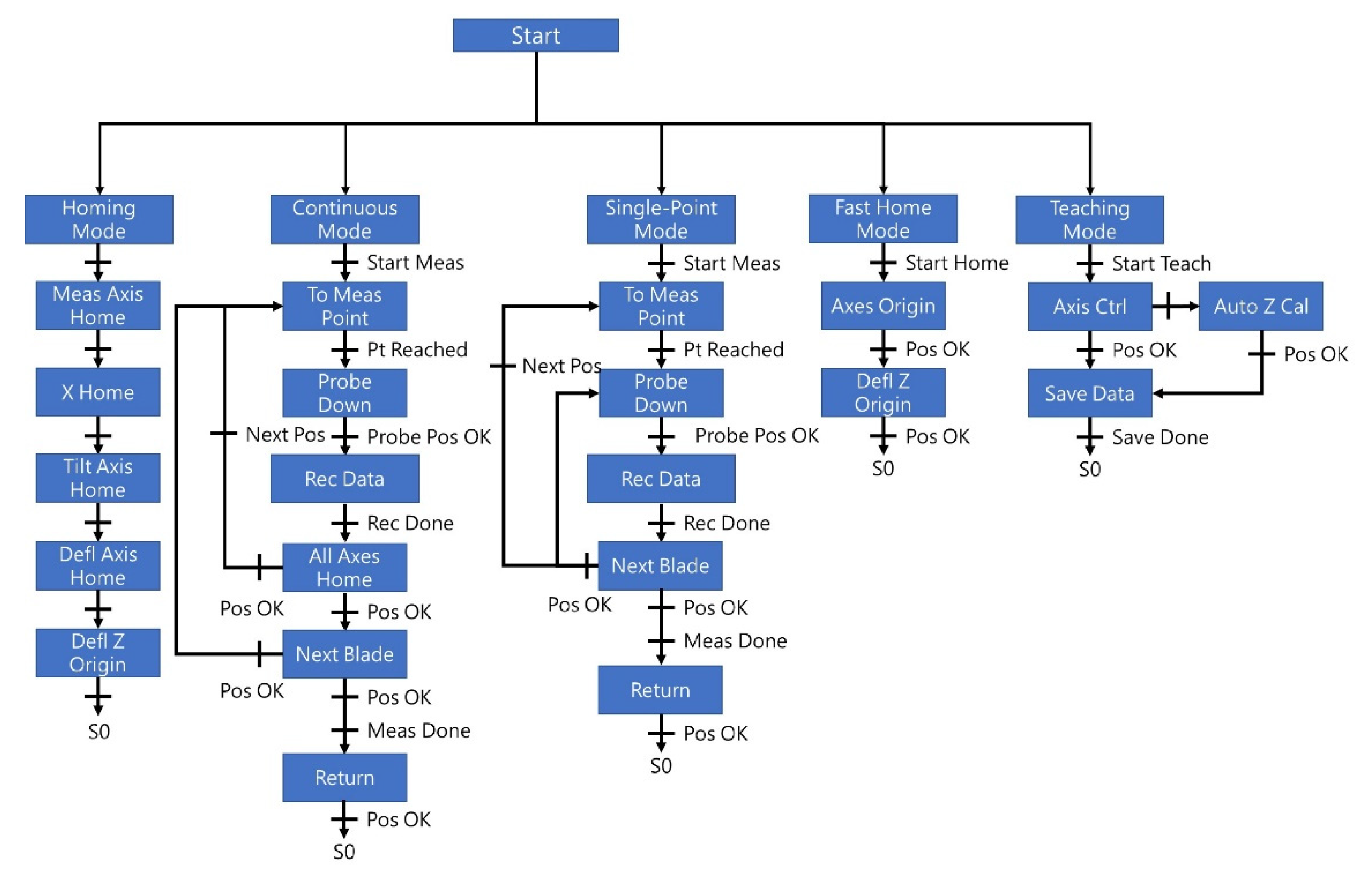
Figure 10.
Main interface page of the HMI.
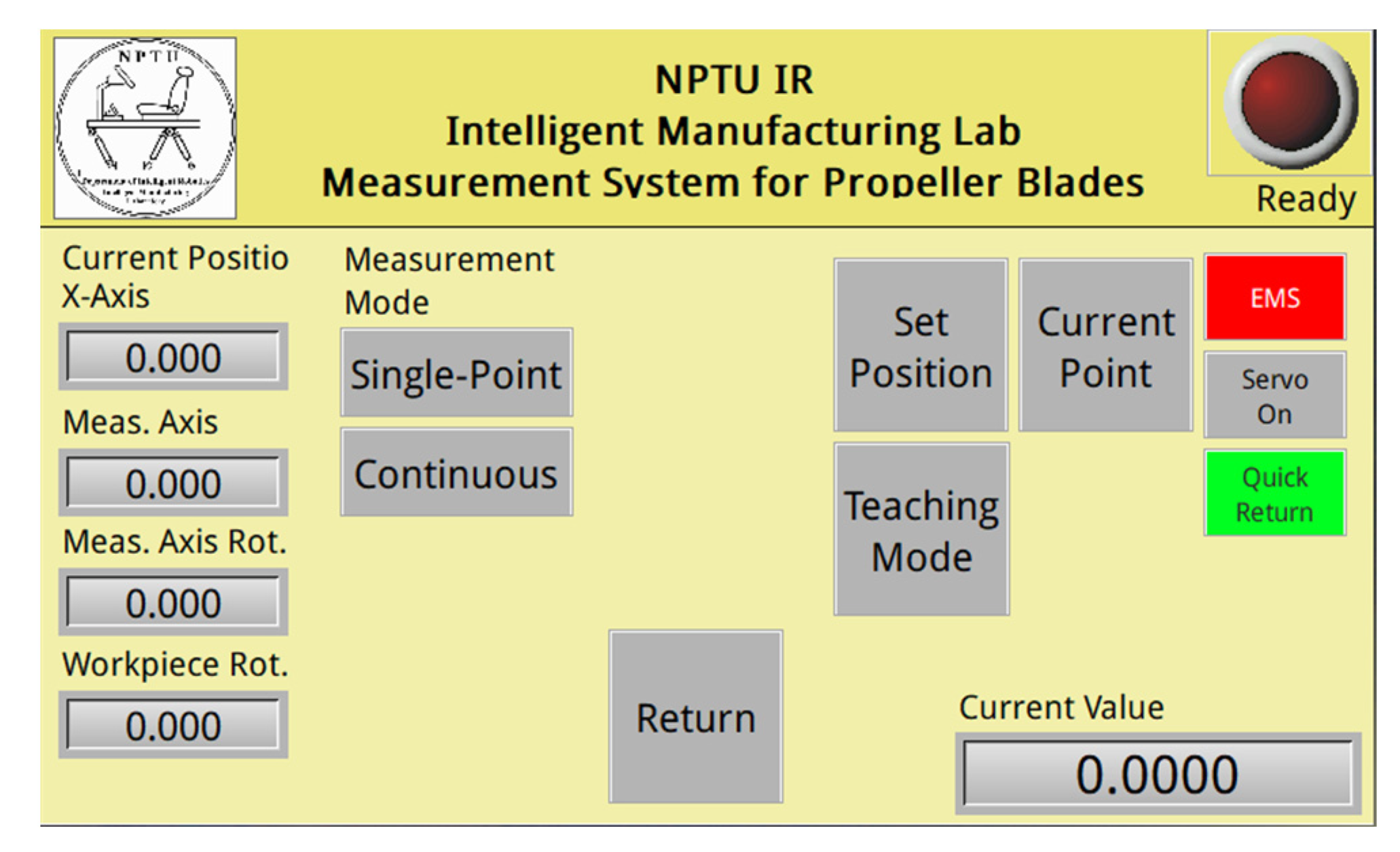
Figure 11.
Continuous measurement mode.
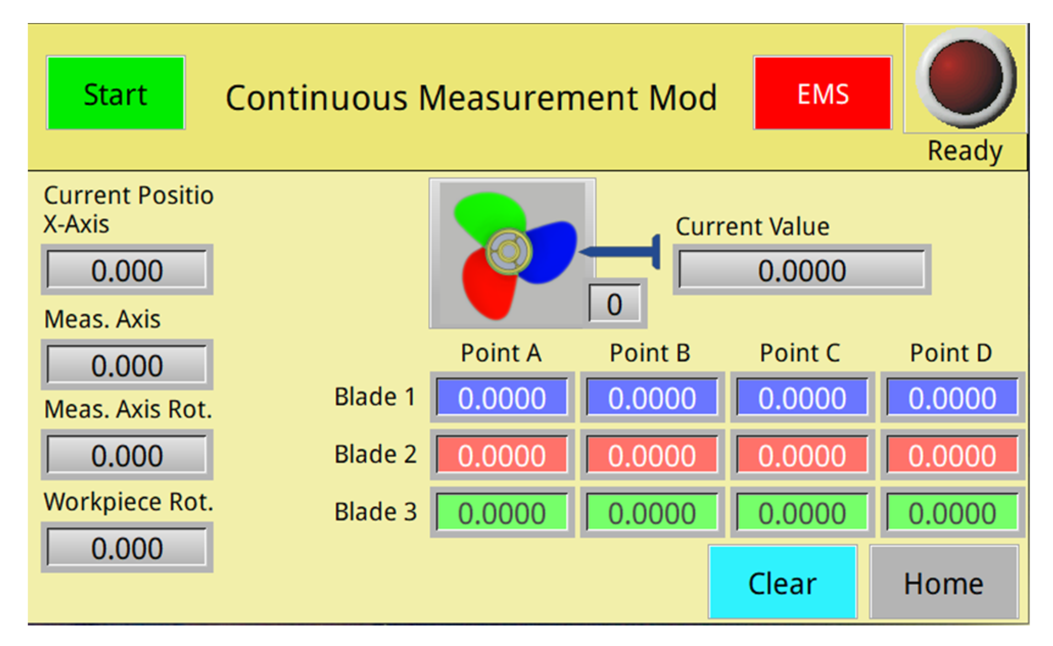
Figure 12.
Single-point measurement mode.
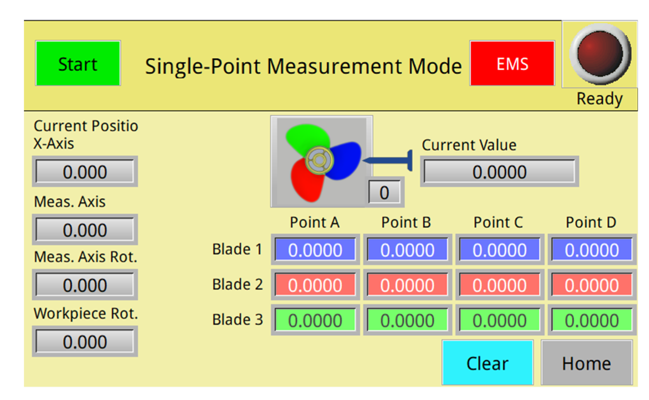
Figure 13.
Teaching mode.
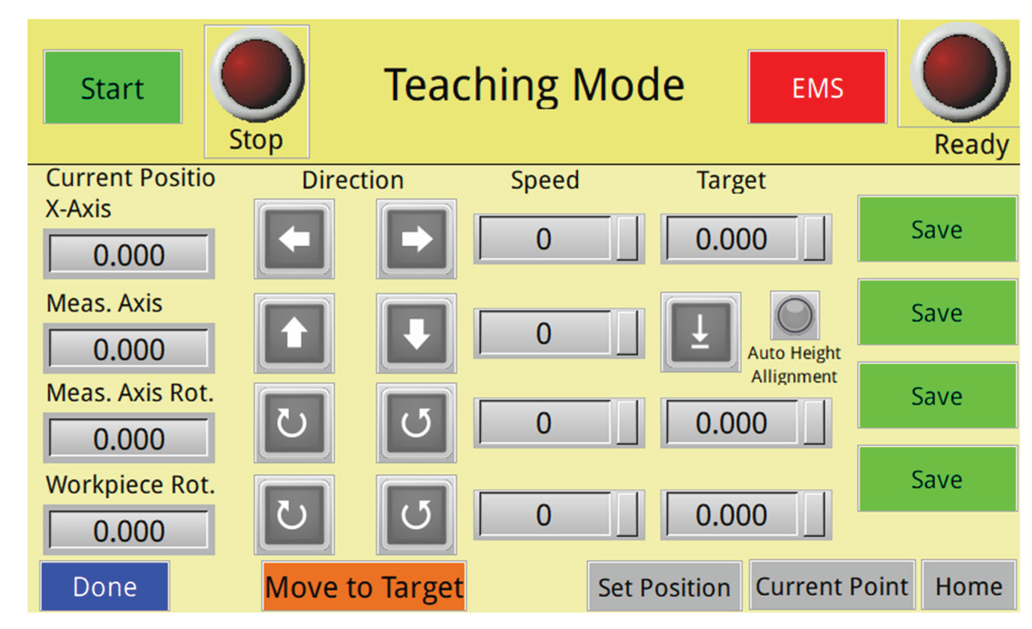
Figure 14.
Interface for inputting the coordinates of each measurement point.
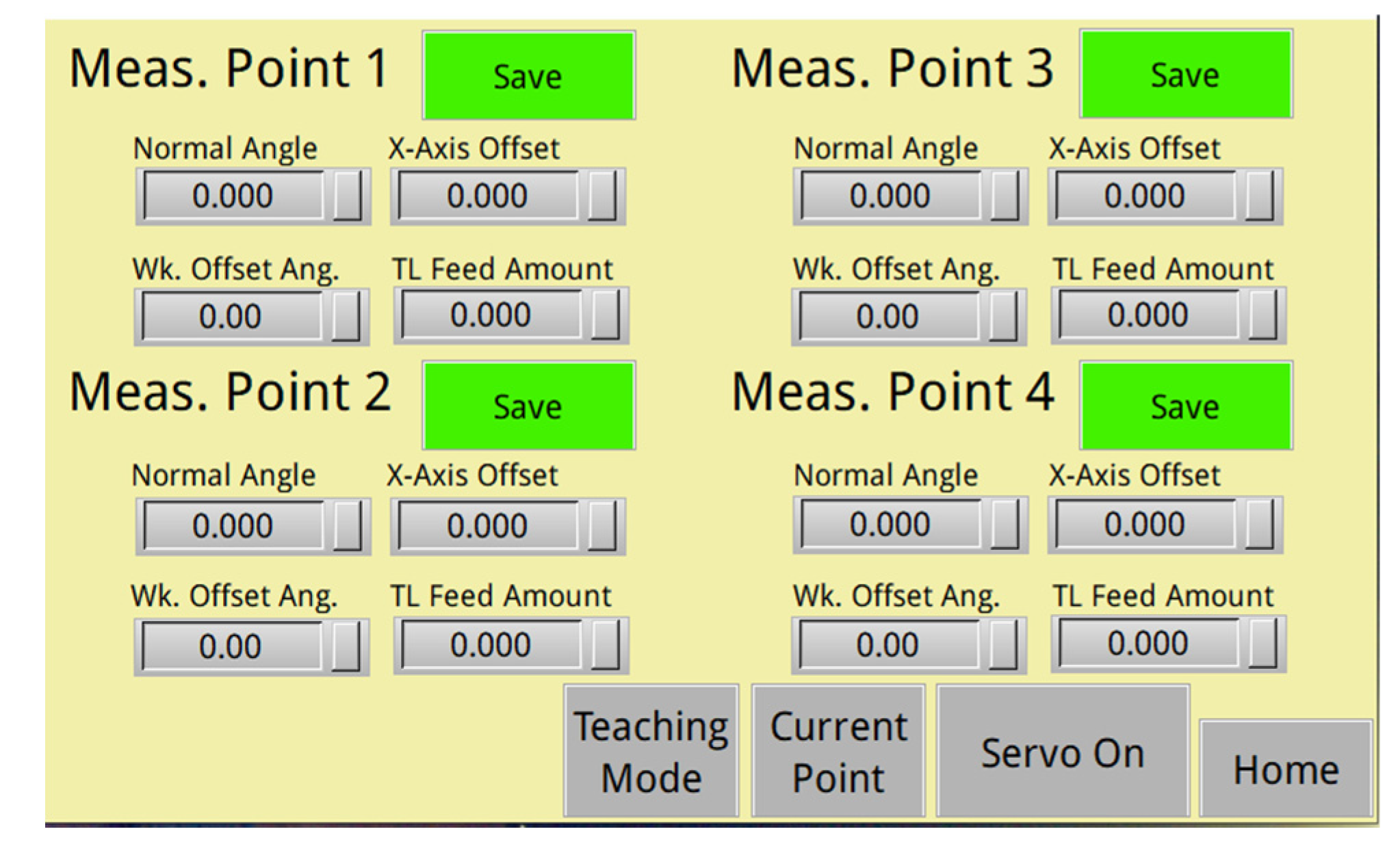

Table 1.
Homogeneity of variance test for decimal precision on the standard platform measurements (N=1200) (***p<0.001).
Table 1.
Homogeneity of variance test for decimal precision on the standard platform measurements (N=1200) (***p<0.001).
| Mean | Variance | Levene statistic | |
|---|---|---|---|
| Second decimal place | 0.29 | 0.213 | ***1779.26 |
| Third decimal place | 4.47 | 7.081 |
Table 2.
Stability analysis of measurement values collected from the standard platform (N=1200).
| Sum of squares | df | Mean square | F | Significance | |
|---|---|---|---|---|---|
| Between-group | 0.016 | 3 | 0.005 | 0.025 | 0.995 |
| Within-group | 254.943 | 1196 | 0.213 | ||
| Total | 254.959 | 1199 |
Table 3.
Homogeneity test results for the continuous measurement mode (***p<0.001).
| Mean | Variance | Levene statistic | ||
|---|---|---|---|---|
| First blade | Second decimal place | 1.21 | 0.750 | ***508.036 |
| Third decimal place | 4.34 | 7.974 | ||
| Second blade | Second decimal place | 1.14 | 0.696 | ***448.148 |
| Third decimal place | 4.32 | 7.287 | ||
| Third blade | Second decimal place | 1.31 | 0.823 | ***343.317 |
| Third decimal place | 4.83 | 6.671 |
Table 4.
Stability analysis of measurement values in the continuous measurement mode.
| Sum of squares | df | Mean square | F | ||
|---|---|---|---|---|---|
| First blade | Between-group | 0.010 | 3 | 0.003 | 0.004 |
| Within-group | 297.180 | 396 | 0.750 | ||
| Total | 297.190 | 399 | |||
| Second blade | Sum of squares | df | Mean square | F | |
| Between-group | 0.188 | 3 | 0.063 | 0.090 | |
| Within-group | 275.590 | 396 | 696 | ||
| Total | 275.778 | 399 | |||
| Third blade | Sum of squares | df | Mean square | F | |
| Between-group | 0.068 | 3 | 0.023 | 0.027 | |
| Within-group | 325.870 | 396 | 0.823 | ||
| Total | 325.937 | 399 |
Table 5.
Homogeneity test for measurement precision in the single-point measurement mode (***p<0.001).
Table 5.
Homogeneity test for measurement precision in the single-point measurement mode (***p<0.001).
| Mean | Variance | Levene statistic | ||
|---|---|---|---|---|
| First blade | Second decimal place | 2.11 | 1.064 | ***403.551 |
| Third decimal place | 4.92 | 8.028 | ||
| Second blade | Second decimal place | 1.76 | 0.802 | ***672.297 |
| Third decimal place | 4.52 | 9.226 | ||
| Third blade | Second decimal place | 1.90 | 0.915 | ***567.765 |
| Third decimal place | 4.36 | 8.603 |
Table 6.
Stability analysis of measurement values in the single-point measurement mode.
| Sum of squares | df | Mean square | F | Significance | ||
|---|---|---|---|---|---|---|
| First blade | Between-group | 1.208 | 3 | 0.403 | 0.378 | 0.769 |
| Within-group | 421.170 | 396 | 1.064 | |||
| Total | 422.377 | 399 | ||||
| Second blade | Between-group | 0.948 | 3 | 0.316 | 0.394 | 0.757 |
| Within-group | 317.490 | 396 | 0.802 | |||
| Total | 318.438 | 399 | ||||
| Third blade | Between-group | 1.580 | 3 | 0.527 | 0.575 | 0.631 |
| Within-group | 362.420 | 396 | 0.915 | |||
| Total | 364.000 | 399 |
Table 7.
Levene’s test for equality of variances in the two measurement modes.
| Mode | Mean | Variance | F | p |
|---|---|---|---|---|
| Continuous measurement mode | 1.23 | 0.868 | 5.684 | ***0.017 |
| Single-point measurement mode | 1.92 | 0.970 |
Table 8.
Independent sample t test.
| t | df | p | Mean difference | Standard error of difference | |
|---|---|---|---|---|---|
| Unequal variance assumed | -18.492 | 2368.835 | **<0.001 | -0.695 | 0.038 |
Disclaimer/Publisher’s Note: The statements, opinions and data contained in all publications are solely those of the individual author(s) and contributor(s) and not of MDPI and/or the editor(s). MDPI and/or the editor(s) disclaim responsibility for any injury to people or property resulting from any ideas, methods, instructions or products referred to in the content. |
© 2025 by the authors. Licensee MDPI, Basel, Switzerland. This article is an open access article distributed under the terms and conditions of the Creative Commons Attribution (CC BY) license (http://creativecommons.org/licenses/by/4.0/).
Copyright: This open access article is published under a Creative Commons CC BY 4.0 license, which permit the free download, distribution, and reuse, provided that the author and preprint are cited in any reuse.


