
Submitted:
12 June 2025
Posted:
16 June 2025
You are already at the latest version
Abstract
In this work, a theoretical study is presented on the combined effects of an external electric field and a nonresonant intense laser field on the electronic properties of a quantum dot (QD) with a truncated cone shape. This QD was made from a type-II CdTe/CdSe heterostructure (core/shell). Using the effective mass approximation with parabolic bands and the finite element method, the Schrödinger equation was solved to analyze the confined states of the electron, hole, and exciton. The study demonstrates the potential for combining nonresonant intense laser and electric fields to control confinement properties in semiconductor nanodevices, with potential applications in optoelectronics and quantum mechanics-related technologies.
Keywords:
truncated conical quantum dot
; electron states
; hole states
; exciton states
; nonresonant intense laser field
; electric field
1. Introduction
In the last few decades, quantum dots (QDs) have attracted the attention of academic and industrial communities. Solution-processed colloidal quantum dots (CQDs) have generated substantial interest because of their high photoluminescence quantum yield, tunable emission, and simple, low-cost solution processability compared to those of their epitaxial counterparts. Their unique electronic properties make them ideal candidates for a wide variety of applications in fields such as medicine [2,46], quantum computation [2], solar cells [2,2], catalysis [2,2], photodetectors [2] and optoelectronics [9,10,11,12]. Concerning the latter, QL-based light emission diodes deserve a special mention given their impact on daily life since their implementation on television screens, which enhances color representation and significantly improves viewing experience [13,14,15]. It is also worth mentioning that control over size and morphology has allowed us to develop synthesis protocols for nanoparticles with nontrivial geometries [16,17,18,19].
In particular, branched nanocrystals such as tetrapods [20,21], single and double quantum rings [22,23,24], and conical QDs [25,26,27] have emerged as strong alternatives for numerous applications due to the peculiar optoelectronic and mechanical properties they exhibit as a result of their nontrivial geometry. For example, engineering their size and composition leads to specific optical properties, such as narrow emission line widths or high photoluminescence quantum yields, which are paramount in designing high-performance photonic devices such as lasers, displays, and sensors. The case of conical QDs is significant due to the possibility of transitioning from a quantum wire for a strongly prolate cone to a quantum well in the case of a strongly oblate one [25]. In addition, adjusting the geometric parameters of the GaAs conical QDs, an ensemble can be modeled to prepare RGB-LED devices, given that the interband transition energy falls into the visible part of the spectrum [28]. Theoretical studies have also demonstrated that for conically shaped QDs, the absorption peak can be shifted to lower incident light energies by externally applying an electric field with increasing intensity [25], while a decrease in size results in a blueshift of the absorption peak of GaAs conical QDs[26].
Advances in chemical synthesis techniques have made it possible to fabricate nanoparticles (NPs) composed of two or more different crystal phases, e.g., core/shell and multilayered QDs, which combine several components with different electronic structures in a single entity. The precise band engineering at the interface of these heterostructures plays an important role in realizing new functional optoelectronic devices, thanks to the formation of type-I and type-II heterostructures [29,30]. Type-II band alignments, especially in CdTe/CdSe core/shell NPs, are ideal candidates for their application in photovoltaics, given their long-range photoinduced charge separation [30,31,32].
The interaction of QDs with nonresonant intense laser fields (ILF) and electric or magnetic fields represents an exciting field of research. It offers opportunities to understand and design advanced materials and devices with specific properties. Combining these factors in studying truncated conical QDs (TCQDs) within type-II heterojunctions adds complexity and potential for future innovative technological applications. In this study, we delve into a detailed exploration of type-II semiconductor nanostructures with a truncated conical geometry. The electron, hole, and exciton states are obtained for a CdTe/CdSe core/shell TCQD with fixed size parameters. They are subjected to nonresonant intense radiation, polarized along the z-axis, and the influence of an external electric field applied along the z-direction. In this way, we demonstrate that it is possible to model irregularities or changes in the geometry of real systems prior to their experimental fabrication.
This paper is organized in the following way: in Section II we present the theoretical model and describe the basic theory, in Section III we present and discuss our numerical results, and finally, our main conclusions are provided in Section IV.
2. Theoretical Framework
This study focuses on the electron, hole, and exciton energy states and their associated wavefunctions in a CdTe/CdSe core/shell TCQD with fixed size parameters under external electric and/or nonresonant ILF. To gain insight into the problem, a schematic representation of the geometry of the core/shell TCQD is provided in Figure 1, together with the main dimensions of the nanostructure and the directions of the electric and laser fields. For clarity, the reference system is also depicted, Cartesian and cylindrical coordinates . A cross section of the structure (with ) is shown in panel (a) of Figure 1, where the two materials that make up the TCQD can be easily identified, i.e., the CdSe and the CdTe. The latter constitutes the -domain and displays a barrier-like behavior, while the former presents a well-like behavior and constitutes the -domain. This configuration is advantageous for building a 2D-axisymmetric model where the azimuthal symmetry simplifies the numerical solution of the Schrödinger equation. Finally, Figure 1(b) shows a 3D view of the TCQD obtained by revolution around the z-axis of Fig.1(a). For calculations, the origin of the reference system is set at the center of the TCQD base.
The transformation of the system under a nonresonant laser field can be modeled using a linearly polarized monochromatic field which incides upon the direction, the vector potential takes the form:
where and are the amplitude and frequency of the laser field, and denotes the unit vector.
The time-dependent Hamiltonian of the problem, within the effective mass approximation, is written in cylindrical coordinates for electrons and holes as follows:
where , is the effective mass in the inner material (CdTe, ) or the outer material (CdSe, ), for the electron and hole, respectively, and for electron and for hole being the absolute value of the elemental charge. Additionally, F designates electric field magnitude, V is the potential value in each of the two materials; for electrons, for CdSe and eV in CdTe. In contrast, for the hole, in CdTe and eV in CdSe.
The Eq. (2) can be simplified using the Kramers-Henneberger transformation [33,34]. This technique incorporates the effect of the laser field by transferring the time dependence from the kinetic term to the potential term [35]. For this reason, the transformation is widely referred to as the laser dressing of the potential. With this, the time-dependent Schrödinger equation takes the time-independent form given by:
with a laser parameter for electrons as
and for hole as
and
The solution of Eq. (3) was sought under the assumption of parabolic bands using the finite element method (FEM) as implemented in the COMSOL-Multiphysics software [36,37,38]. The boundary conditions were imposed in the following way: i) wave function continuity on the core-shell interface, , ii) BenDaniel-Duke boundary condition: with , and iii) Dirichlet boundary conditions on the outer surface of the CdTe/CdSe core/shell TCQD: . For computational efficiency, the system is divided into two regions as indicated in Figure 1(a): the first region consists of CdTe, while the second consists of CdSe.
By expanding the first term in Equation 3 and applying the azimuthal symmetry condition of the system, it is possible to assume a solution in cylindrical coordinates of the form . As a consequence, the function must satisfy the following differential equation
where is the azimuthal quantum number and is the two-dimensional Laplacian operator in the polar coordinates.
During the calculations, Eqs. (3) and (7) are used as the two fundamental models to be solved. Eq. (3) provides a general framework for describing the behavior of the system under the influence of external fields. In particular, Equation (7) reveals the quantum number associated with each state, which enables the identification of the type of wavefunction involved, thus offering a more detailed characterization of the electronic states. Moreover, since Equation (7) corresponds to a 2D axisymmetric model, it significantly reduces the computational cost compared to a full 3D calculation, while still capturing the essential physics of the system.
After obtaining the uncorrelated ground-state wavefunctions for the electron and hole, denoted by and , respectively, we can evaluate the excitonic contribution from the Coulomb interaction between the two charges. Within the framework of first-order perturbation theory, the Coulomb integral takes the form:
where and are the volume differentials in cylindrical coordinates for the electron and hole, respectively. The integration domains and indicate the full volume of the cone represented in Figure 1(b)
The angular dependence in Eq. (7) can be integrated analytically because of the azimuthal symmetry. The six-dimensional integral becomes four-dimensional. The Coulomb term then simplifies to
where , , is the complete elliptic integral of the first kind, , and . Here, the domain region for the integrals corresponds to the surface depicted in Figure 1(a).
3. Results and Discussion
The Schrödinger equation, given in Eq. (3), was solved using FEM via COMSOL-Multiphysics software [36,37,38] within the effective mass approximation. We investigated numerically the lowest confined energy states for electrons and holes in a CdTe/CdSe core/shell TCQD subjected to an electric in/or intense nonresonant laser field as a function of the intensity of the electric field, F, and the laser field parameter, . The parameters for electrons and holes adopted in the numerical calculations are , , , (here, is the mass of free electrons). The barrier heights are meV and for electrons and and eV for holes in CdTe/CdSe TCQD [31].
Figure 2 shows a cross-sectional profile of the confinement potential for electrons in the TCQD. The first panel of this figure corresponds to the absence of a laser field, which allows us to differentiate the boundary between the two building materials, CdSe in blue and CdTe in red. The color scale depicted ranges from zero (blue) to the maximum value of 0.420 eV (red), matching the potential values aforementioned for electrons and . The maximum potential at the CdTe core and the rotational symmetry give rise to a wavefunction similar to that obtained in a quantum ring. Figure 2(b) illustrates how the barrier height and the well width decrease when an ILF of nm is applied to the nanostructure. At this laser intensity, the potential barrier still creates significant confinement on the electron, preventing its wavefunction from penetrating the core region of the truncated cone. In Figure 2(c), the changes in the potential shape resulting from the effect of the external laser field of nm are exhibited. The red region is remarkably reduced, replaced by intermediate confinement zones, identified by green and light blue colors, making it easier for the electron wavefunction to enter the CdTe core. However, it will not extend to the entire core, as the center still has a barrier. At the base of the cone, the laser causes an irregular confinement region, as the zero potential extends into the CdTe. For this laser intensity, the electron exhibits a smaller barrier effect and is more likely found at the base, where a wider region of zero potential appears. The effect of the highest intensity laser used in this work, i. e. nm, is shown in Figure 2(d). It is straightforward that the eV barrier is completely lost, being now lower in height and, therefore, allowing the wavefunctions of the low-lying electron states to enter the core. The ring behavior exhibited due to natural confinement in the type II heterojunction in the previous cases is largely lost. Finally, the dashed lines plotted at nm in panels (a), (c), and (d) of Figure 2 correspond to the location of the cut plane for Figure 3 (see below).
The confinement potential associated with the three values of laser parameters analyzed in this work is presented in Figure 3 on a transverse section at half the TCQD height, i.e., nm. It is important to note that there exists an infinite barrier beginning at nm and continuing along the cone generatrix, which is independent of the inclusion of the ILF and which, in an actual situation, would represent the air exposure of the outer surface. For clarity, vertical arrows indicating the existence of this infinite barrier are displayed in panel (a) of Figure 3, which is valid throughout the study. The theoretical model was implemented using the Dirichlet boundary condition. Looking at panels (b)-(d) it is straightforward that an increase in the laser field intensity turns into a reduction in the confinement potential barrier for electrons, which will allow for an increasing penetration of the low-lying electron wavefunctions in the core region, which otherwise would not be possible. These effects, modeled by a dressed potential, are equivalent to having an irregular cone, so it would be possible to model irregularities or changes in the geometry of real systems prior to their experimental fabrication.
Analogously, Figure 4 shows the confinement potential associated with the three laser parameter values under study on a transverse section at the TCQD base, i.e., nm. Following the arguments presented when discussing Figure 3, in the case of Figure 4(a) vertical arrows are displayed to indicate the infinite barrier corresponding to the outer surface of the nanostructure, now located at nm. From this panel, it is evident that the ILF reduces the barrier both in height and width, which gives rise to a lighter electron confinement. As the laser parameter increases, panels (b)-(d), the probability of finding the electron in the bottom region of the nanostructure increases as a consequence of the diminishing barrier observed in this area. This fact is also reinforced by the results already presented in Figure 3.
In Figure 5, the energies of an electron confined in the CdTe/CdSe core/shell TCQD presented in Figure 1 are presented as functions of the laser parameter, . Two sets of results are shown, solid lines are associated to the 2D-axisymmetric model, while dotted lines correspond to the 3D model. One of the advantages of using the 2D axisymmetric model is the possibility of unequivocally identifying the quantum number l. In addition, a remarkable reduction in the computational cost is achieved concerning the 3D model due to axial symmetry. The potential barrier generated by the different materials is eV. It can be seen that the energy of the low-lying states increases with the laser parameter, up to approximately nm. This is explained by the fact that the width of the well is being reduced while the barrier is still high, giving rise to a greater electron confinement. From this value on, a gradual decrease in the aforementioned energies is observed, since, although the well becomes narrower in most of the structure, the barrier has dropped enough to decrease its confining effect. Furthermore, as discussed in Figure 3, for values of nm the well evolves into a wider shape, which keeps the electron mainly in the bottom region of the TCQD. The combined effect of a lower barrier and a wider well at the base implies less confinement, which is reflected in the drop in energies. For completeness, the electron probability densities associated with the laser parameters , , and nm are shown at the top of Figure 5 to clarify the effect of ILF on the nanostructure. When , a quantum ring-like behavior is observed for the electron located within the CdSe region. For an intermediate value of the laser parameter, a more defined quantum ring-like probability density is observed, i.e., a washer-shaped distribution [39]. For the third case, nm, we have a system that behaves fundamentally as a QD, losing the double connectedness typical of a quantum ring, as pointed out when discussing Figure 2.
Figure 6 shows an analysis of the first low-lying electron states as functions of the externally applied electric field and ILF. Panels (a-c) show the energy variation of the lowest states with quantum numbers , , and for three values of the laser parameters. The negative value of the electric field intensity means that it points towards the negative z-axis. In the absence of an electric field, the energies of the different electron states decrease as the laser parameter increases. On the other hand, if the value of is fixed, the energy of the states increases with the intensity of the electric field directed towards the positive z-direction. It decreases when the absolute value of the electric field increases if it is directed towards the negative z-axis. Panel 6(d) shows the electron probability density corresponding to the ground state with for three different values of the laser parameter and for the three extreme values of the applied electric field, i.e., , , and kV/cm. In all cases it can be seen how the probability of finding the electron shifts downwards as the electric field changes from pointing toward the negative to the positive z-axis; being remarkable the case of nm, where the confining effect of the ILF is so strong that the electric field effect is nearly negligible. An increase in the value of the laser parameter translates into a greater penetration of the electron wavefunction into the core region, thanks to the reduction it causes in the CdTe barrier, as has already been discussed with the potentials presented in Figure 2, 3, and 4. This justifies the greater probability of finding the electron in the core region when the electric field points towards the negative z-direction. The effect of the electric field on the wavefunction is more dramatically appreciated in both the absence and the ILF’s maximum value. In contrast, it is nearly neutralized for an intermediate value, indicating the competition between these fields when applied to the nanostructure. The above shows that the laser field can be adjusted to magnify or minimize the effect of the externally applied electric field.
Figure 7 shows a cross-sectional view of the hole confinement potential. In this system the hole is confined within the CdTe region, while CdSe behaves as the barrier material. Comparing Figure 7(a), which corresponds to no-ILF, with Figure 7(b-d), where the laser parameter is 3 nm, 5 nm, and 10 nm, respectively, the laser shrinks the effective confinement region. The progressive evolution observed across these panels highlights how the ILF modifies the confinement potential, providing a basis for analyzing the corresponding changes in the hole energy spectrum as the laser alters the system. In contrast to the electron case (Figure 2), the effective potential of the hole shows a weaker response to increasing the laser parameter . Although there is a slight modulation of the potential, particularly near the base of the cone, the laser-induced effects are significantly smaller. This difference can be explained by several physical factors. First, the hole has a much larger effective mass than the electron which makes it less sensitive to external perturbations due to its higher inertia. Within the dressed potential model, the modulation of the confinement potential induced by the laser field is inversely proportional to the effective mass. Therefore, the impact of the laser on the hole confinement is considerably reduced. Additionally, in this type-II heterostructure, the hole is confined within the CdTe core, where the potential well is deeper (0.57 eV). This contrasts with the electron, which is located in the CdSe shell, a region with a shallower potential that is more easily altered by the laser field. As a result, the wavefunction of the hole remains more localized and centered, and the laser field does not affect either the confinement profile or the spatial distribution of the carrier. Taken together, these factors explain why the hole confinement remains with small changes with increasing laser intensity, in contrast to the electron case, where a reduction in the confinement barrier and wavefunction redistribution are observed.
Figure 8 shows that the confinement profile mainly affects the lowest-lying states and those approaching the barrier. Because our targets are precisely these low-energy states, an ILF can be used to tune the hole states of interest. The 3D views reveal in detail how the ILF reshapes the potential; at modest laser amplitudes, the changes are subtle, so a more intense laser is required to produce confinement alterations for the hole comparable to those already obtained for the electron.
In Figure 9, an intermediate height barrier emerges for holes, preventing any significant probability density from accumulating near the CdTe edges. Panels 9(c) and 9(d) confirm that the in-plane () confinement is practically identical for nm and 10 nm; the appreciable variations appear only in larger z, consistent with the trends discussed for Figure 8. The hole remains localized in the center of the CdTe region. The lateral confinement in the plane is almost unaffected. Even at high laser intensities, the in-plane potential remains relatively unchanged. This is due to the strong and deep potential well of the CdTe core and to the fact that the laser field has limited influence over the radial direction in this region. The results confirm that the hole remains strongly confined at the base, and the laser field alone is not enough to modify its radial confinement significantly.
Figure 10 shows the evolution of the hole energy levels as a function of the laser parameter , by using both the 2D axisymmetric model (solid lines) and the full 3D model (dotted lines). The good agreement between the two models confirms the validity of the axisymmetric approximation for describing hole states in this system. As laser parameter increases, the energy levels of the hole also rise. In this system, the laser field does not globally reduce or increase the confinement potential. Instead, it modifies the confinement in a localized manner, particularly growing the effective confinement near the base of the truncated cone. As seen in Figures (7)-(9), the laser-induced potential reshaping leads to a stronger confinement along the z-axis at the lower part of the nanostructure, where the hole wavefunction is primarily located. This localized enhancement of the confinement compresses the hole wavefunction along the vertical direction, shifting the energy levels upward. Meanwhile, the upper part of the barrier may experience a slight reduction in height as a result of the laser field. However, since the hole remains mostly localized in the lower (CdTe) region of the structure, this has a negligible effect on the low-lying states. The probability densities plotted above Figure 10 confirm that the hole wavefunction becomes slightly more localized as increases, particularly along the z-direction, while retaining its overall symmetry. These findings indicate that the laser field acts as a selective tuning mechanism that enhances confinement locally, rather than uniformly across the entire structure.
In Figure 11(d), moving down the rows (i.e., increasing ), one sees that the laser reduces the volume of the probability density, in agreement with the dressed potential analysis. For a negative z-directed electric field ( kV/cm, first column), the hole, being a positive carrier, shifts in the same direction as the field; compare this with the second column, where no electric field is applied. The third column illustrates the effect of a positive z-directed field ( kV/cm), which pushes the hole towards the cone apex. In both field orientations, competition arises between ILF and electric field effects; for example, at nm the ILF dominates because the laser-induced change in effective confinement outweighs the influence of the electric field.
Figure 12 plots the electron-hole Coulomb energy versus for three cases: (i) no electric field (), (ii) kV/cm, and (iii) kV/cm. For small laser parameters, roughly nm, the exciton energy stays constant because the individual confinements of electron and hole are not altered enough to affect their interaction. With no electric field, the Coulomb energy decreases for 2 nm nm: the electron is drawn to the CdSe base while the effective region of the hole in CdTe shrinks, increasing their separation. For nm the interaction strengthens because the electron begins to penetrate the CdTe core, triggering a transition from an indirect to a direct exciton.
When a positive electric field is applied ( kV/cm) the confinements of the carriers resemble the case, so the curve retains the same shape but shifts downward in energy: the field pulls electron and hole in opposite z directions, enlarging their separation. By contrast, for kV/cm the Coulomb energy rises monotonically -even within the 2–4 nm interval where it previously fell-. A negative z-directed field squeezes the hole density toward the cone base; at these values the electron still resides near the base, though in CdSe, so the carriers move closer together, enhancing their interaction. These results underscore that the combined ILF and electric field can be used to tailor excitonic properties in a highly directional and intensity-dependent way.
4. Conclusions
In conclusion, this work demonstrates the significant impact of combining an external electric field and an intense non-resonant laser field (ILF) on the electronic properties of a quantum dot with a truncated cone geometry (CdTe/CdSe). The modeling, based on the effective mass approximation and finite element method, reveals that the laser field has the ability to modify the properties of the confinement in a manner comparable to geometric alterations. In particular, the laser field can transform the original ring-like quantum dot geometry into a dot-like quantum dot, achieved through the reduction of the potential barrier and the widening of the well at the cone base. This effect offers a useful tool for simulating structural irregularities and changes before experimentally synthesizing the nanodevice.
Furthermore, the study highlights the role of laser intensity as a tool to control quantum confinement. At intermediate laser intensities (around nm), a maximum in the ground state energy is observed, suggesting a delicate balance between laser-induced effects and confinement properties. The external electric field also plays a crucial role, with its influence being amplified or attenuated depending on the laser parameters. In the presence of an intermediate laser field, the effect of the electric field becomes nearly negligible, revealing the competition between these two external fields.
The analysis of the evolution of confinement and energy spectra for both electrons and holes confirms that the interaction between the laser and electric field enables manipulation of carrier localization, affecting their respective states. For excitons, the combined effect of these fields facilitates the tuning of the Coulomb interaction energy, allowing even a transition from an indirect to a direct exciton. This presents a promising approach for designing optoelectronic devices, as the manipulation of quantum confinement and excitonic properties opens new possibilities for the development of advanced semiconductor nanodevices.
Author Contributions
J. Sierra-Ortega, C. A. Duque, J. A. Vinasco, Gene Elizabeth Escorcia-Salas, A. L. Morales: Conceptualization, software, formal analysis, supervision, writing, methodology. F. Amador Donado, F. Guerrero Almanza, C. Frías Viña Software, Formal analysis, investigation, writing. R. V. H. Hahn, M. E. Mora-Ramos, O. Mommadi, A. El Moussaouy, R. Boussetta, D. Duque, S. Urán-Parra Analysis, writing, revision. All authors have read and agreed to the published version of the manuscript.
Data Availability Statement
No new data were created or analyzed in this study. Data sharing is not applicable to this article.
Acknowledgments
The authors are grateful to the Colombian Agencies: CODI-Universidad de Antioquia (Estrategia de Sostenibilidad de la Universidad de Antioquia and projects "Complejos excitónicos y propiedades de transporte en sistemas nanométricos de semiconductores con simetría axial basados en GaAs e InAs", and "Nanoestructuras semiconductoras con simetría axial basadas en InAs y GaAs para aplicaciones en electrónica ultra e híper rápida") and Facultad de Ciencias Exactas y Naturales-Universidad de Antioquia (CAD exclusive dedication project 2025–2026). MEMR acknowledges support from Mexican CONAHCYT through Grant CB 2017-2018 No. A1-S-8218. JAV acknowledges the support from the Universidad Nacional de Colombia Sede Palmira to develop this research. RVHH gratefully acknowledges financial support from the Spanish Junta de Andalucía through a Doctoral Training Grant PREDOC-01408.
Conflicts of Interest
The authors do not have any financial and non-financial competing interests statement.
References
- P. K. Chattopadhyay, D. A. Price, Th. F. Harper, M. R. Betts, J. Yu, E. Gostick, S. P. Perfetto, P. Goepfert,R. A. Koup, S. C. De Rosa, M. P. Bruchez and M. Roederer, “Quantum dot semiconductor nanocrystals for immunophenotyping by polychromatic flow cytometry”. Nat. Med., 2006, 12, 972–977.
- J. Kolosnjaj-Tabi, Y. Javed, L. Lartigue, J. Volatron, D. Elgrabli, I. Marangon, G. Pugliese, B. Caron, A. Figuerola, N. Luciani, T. Pellegrino, D. Alloyeau and F. Gazeau, “The One Year Fate of Iron Oxide Coated Gold Nanoparticles in Mice”. ACS Nano 2015, 9, 7925–7939.
- K. S. Rahul, K. Salini and V. Mathew, "Electronic properties of an exciton in CdTe/CdSe/CdTe/CdSe type-II nano-heterostructure". J. Phys.: Condens. Matter, 2016, 28.
- J. Maleki, M. Eskandari and D. Fathi, "New design and optimization of half-tandem quantum dot solar cell: Over 30% power conversion efficiency using nanostructure oriented core-shell". Renew. Energy 2024, 222.
- R. V. H. Hahn, S. Rodríguez-Bolívar, P. Rodosthenous, E. S. Skibinsky-Gitlin, M. Califano and F. M. Gómez-Campos, "Optical Absorption in N-Dimensional Colloidal Quantum Dot Arrays: Influence of Stoichiometry and Applications in Intermediate Band Solar Cells". Nanomaterials 2022, 12.
- H. Lee, S. E. Habas, S. Kweskin, D. Butcher, G. A. Somorjai, y P. Yang, “Morphological control of catalytically active platinum nanocrystals”. Angew. Chem. Weinheim Bergstr. Ger. 2006, 118, 7988–7992.
- M. Ikram, S. Moeen, A. Haider, A. Ul-Hamid, H. Alhummiany, H. H. Somaily, S. Goumri-Said and M. Benali Kanoun, "Experimental and computational study of annealed nickel sulfide quantum dots for catalytic and antibacterial activity". Nano Materials Science 2024, 6.
- T. Zou, T. Choi, A. Liu, H. Zhu and Y. Noh, "Printed quantum dot photodetectors for applications from the high-energy to the infrared region". Nano Energy 2024, 125.
- I. Ramiro, E. Kundu, N. Dalmases, O. Özdemir, M. Pedrosa and G. Konstantatos, "Size- and Temperature-Dependent Intraband Optical Properties of Heavily n-Doped PbS Colloidal Quantum Dot Solid-State Films". ACS Nano 2020, 14.
- F. Chen, Q. Lin, H. Shen and A. Tang, "Blue quantum dot-based electroluminescent light-emitting diodes". Mater. Chem. Front. 2020, 4, 1340–1365. [CrossRef]
- G. Pan, X. Bai, W. Xu, X. Chen, Y. Zhai, J. Zhu, H. Shao, N. Ding, L. Xu, B. Dong, Y. Mao and H. Song, "Bright Blue Light Emission of Ni2+ Ion-Doped CsPbClxBr3-x Perovskite Quantum Dots Enabling Efficient Light-Emitting Devices". ACS Appl. Mater. Interfaces 2020, 12, 14195–14202. [CrossRef] [PubMed]
- L. Meng, Q. Xu, J. Zhang and X. Wang, "Colloidal quantum dot materials for next-generation near-infrared optoelectronics". Chem. Commun. 2024, 60.
- Z. Chen, H. Li, C. Yuan, P. Gao, Q. Su and Sh. Chen, "Color Revolution: Prospects and Challenges of Quantum-Dot Light-Emitting Diode Display Technologies". Small Methods 2024, 8.
- X. Li, Sh. Sun, Y. Zhang, X. Gu,C. Liang, T. Tanaka and J. Li, "CdSe/ZnS Quantum Dot Patterned Arrays for Full-Color Light-Emitting Diodes in Active-Matrix QLED Display". ACS Appl. Nano Mater. 2024, 7.
- J. Fan, Ch. Han, G. Yang, B. Song, R. Xu, Ch. Xiang, T. Zhang and L. Qian, "Recent Progress of Quantum Dots Light-Emitting Diodes: Materials, Device Structures, and Display Applications". Adv. Mater. 2024, 36.
- S. Kim, S. Park, M. Kim and S. Jeong, "Synthesis of single-crystalline InP tetrapod nanocrystals via addition of ZnCl2". Bull. Korean Chem. Soc. 2023, 44.
- H. Lee, D. Yoon, S. Koh, M. Kang, S. Moon, J. Lim and D. C. Lee, "Ligands as a universal molecular toolkit in synthesis and assembly of semiconductor nanocrystals". Chem. Sci. 2020, 11.
- F. Huang, J. Ning, Z. Duan, A. A. Sergeev, A. Portniagin, S. V. Kershaw, J. Tian and A. L. Rogach, "Induction of Wurtzite to Zinc-Blende Phase Transformation in ZnSe Nanorods During Cu(I) Cation Exchange". Chem. Mat. 2021, 33.
- J. K. Utterback, J. L. Ruzicka, H. Hamby, J. D. Eaves and G. Dukovic, "Temperature-Dependent Transient Absorption Spectroscopy Elucidates Trapped-Hole Dynamics in CdS and CdSe Nanorods". J. Phys. Chem. Lett. 2019, 10, 2782–2787. [CrossRef]
- N. Mishra, V. G. Vasavi Dutt M. P. Arciniegas, "Recent Progress on Metal Chalcogenide Semiconductor Tetrapod-Shaped Colloidal Nanocrystals and their Applications in Optoelectronics". Chem Mater. 2019, 31.
- R. V. H. Hahn, F. Mora-Rey, R. L. Restrepo, A. L. Morales, J. Montoya-Sánchez, G. Eramo, M. G. Barseghyan, A. Ed-Dahmouny, J. A. Vinasco, D. A. Duque and C. A. Duque, "Electronic and optical properties of tetrapod quantum dots under applied electric and magnetic fields". Eur. Phys. J. Plus 2024, 139.
- D. A. Ospina, D. Duque, M. E. Mora-Ramos, J. A. Vinasco, A. Radu, R. L. Restrepo, A. L. Morales, J. Sierra-Ortega, Gene Elizabeth Escorcia-Salas, M. A. Giraldo, J. Montoya-Sanchez and C. A. Duque, "Hopf-link GaAs-AlGaAs quantum ring under geometric and external field settings". Phys. E: Low-Dimens. Syst. Nanostructures, 2024, 163.
- R. V. H. Hahn, C. A. Duque and M. E. Mora-Ramos, "Electron-impurity states in concentric double quantum rings and related optical properties". Phys. Lett. A 2025, 534.
- J. M. García, G. Medeiros-Ribeiro, K. Schmidt, T. Ngo, J. L. Feng, A. Lorke, J. Kotthaus and P. M. Petroff, "Intermixing and shape changes during the formation of InAs self-assembled quantum dots". Appl. Phys. Lett. 1997, 71.
- K. S. Khachatryan, M. A. Mkrtchyan, D. B. Hayrapetyan, E. M. Kazaryan, y H. A. Sarkisyan, “Adiabatic description of the electroabsorption in strongly prolate and oblate conical quantum dots”. Physica E Low Dimens. Syst. Nanostruct 2021, 134, 114887. [CrossRef]
- S. P. Gavalajyan, G. A. Mantashian, G. Ts. Kharatyan, H. A. Sarkisyan, P. A. Mantashyan, S. Baskoutas and D. B. Hayrapetyan, "Optical Properties of Conical Quantum Dot: Exciton-Related Raman Scattering, Interband Absorption and Photoluminescence". Nanomaterials 2023, 13.
- N. M. Ali and Y. M. El-Batawy, "Modeling of light absorption in self-assembled truncated conical quantum dot structures". Opt. Quant. Electron. 2023, 56.
- D. B. Hayrapetyan, E. M. Kazaryan and H. A. Sarkisyan, "Magneto-absorption in conical quantum dot ensemble: Possible applications for QD LED". Opt. Commun. 2016, 371.
- S. Kim, B. Fisher, H.-J. Eisler and M. Bawendi, "Type-II Quantum Dots: CdTe/CdSe(Core/Shell) and CdSe/ZnTe(Core/Shell) Heterostructures". J. Am. Chem. Soc. 2003, 125.
- S. Kumar, M. Jones, Sh. S. Lo and G. D. Scholes, "Nanorod Heterostructures Showing Photoinduced Charge Separation". Small 2007, 3.
- L. Pulgar-Velásquez et al., “Shallow donor impurity states with excitonic contribution in GaAs/AlGaAs and CdTe/CdSe truncated conical quantum dots under applied magnetic field”, Nanomaterials, vol. 11, no. 2832, October 2021.
- Y. Yao, T. Kuroda, D. N. Dirin, M. S. Sokolikova and R. B. Vasiliev, "Strain effects on optical properties of tetrapod-shaped CdTe/CdS core/shell nanocrystals". Superlattices Microstruct. 2014, 76.
- W. C. Henneberger, "Perturbation Method for Atoms in Intense Light Beams". Phys. Rev. Lett. 1968, 21.
- K. Burnett, V. C. Reed, and P. L. Knight, "Atoms in ultra-intense laser fields". J. Phys. B: At. Mol. Opt. Phys. 1993, 26.
- F. M. S. Lima, M. A. Amato, O. A. C. Nunes, A. L. A. Fonseca, B. G. Enders and E. F. da Silva, "Unexpected transition from single to double quantum well potential induced by intense laser fields in a semiconductor quantum well". J. Appl. Phys. 2009, 105.
- COMSOL. Multiphysics; v. 6.3; COMSOL AB: Stockholm, Sweden.
- COMSOL. Multiphysics Reference Guide. Stockholm, Sweden, 2012.
- COMSOL. Multiphysics Users Guide. Stockholm, Sweden, 2012.
- J. A. Barker, R. J. Warburton and E. P. O’Reilly, "Electron and hole wave functions in self-assembled quantum rings". Phys. Rev. B 2004, 69.
Figure 1.
Schematic representation of the (a) cross section and (b) 3D view of the core/shell CdTe/CdSe TCQD with fixed geometrical parameters nm, nm, nm and nm. The directions of both electric field and polarization of the laser field are also shown. The core/shell material is CdTe/CdSe. A vacuum surrounds the heterostructure.
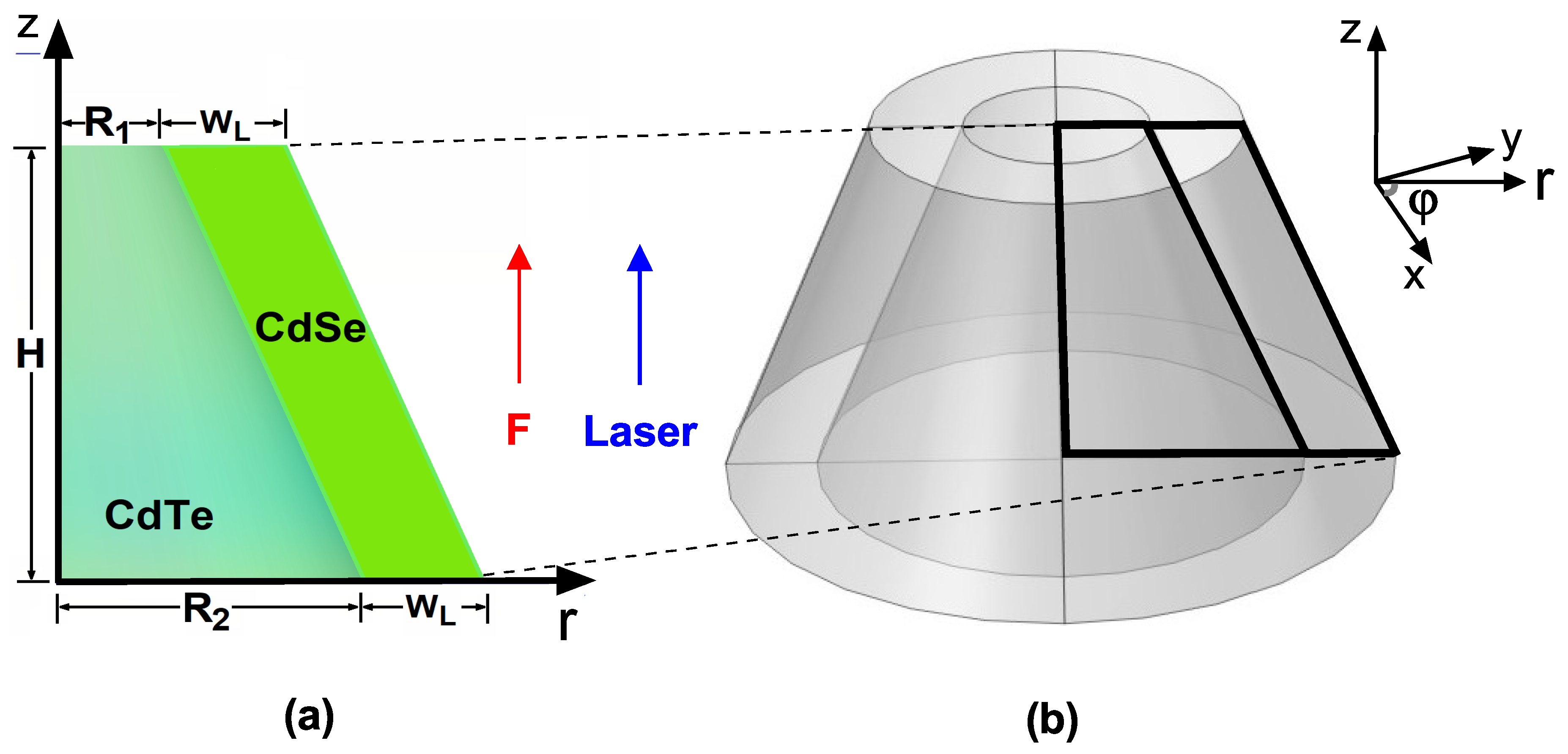
Figure 2.
Cross section of the electron confinement potential in a CdTe/CdSe core/shell TCQD associated with (a) , (b) nm, (c) nm, and (d) nm. The geometrical parameters of the structure are kept constant with values nm, nm, nm, and nm. Additionally, .
Figure 2.
Cross section of the electron confinement potential in a CdTe/CdSe core/shell TCQD associated with (a) , (b) nm, (c) nm, and (d) nm. The geometrical parameters of the structure are kept constant with values nm, nm, nm, and nm. Additionally, .
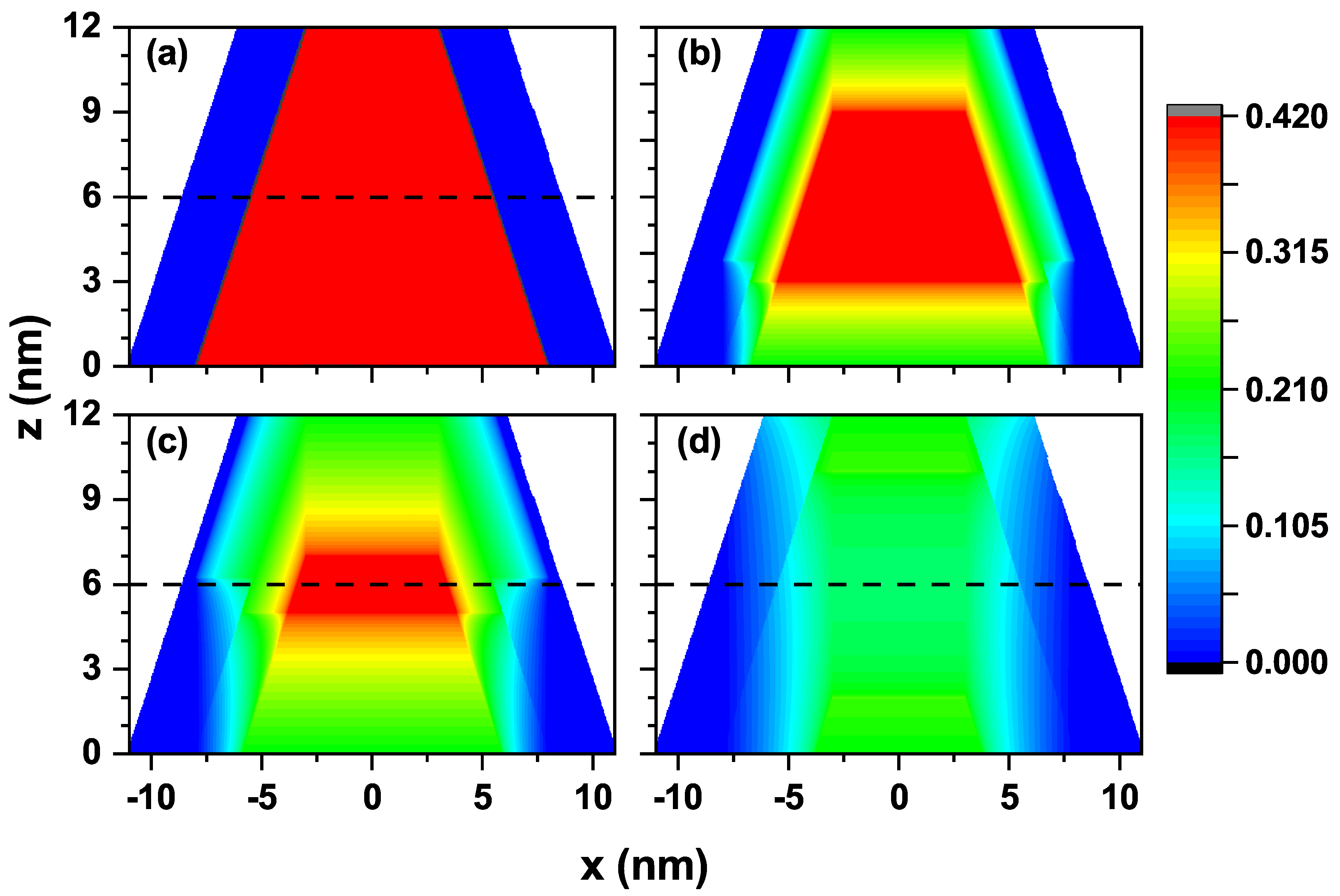
Figure 3.
Representation of the electron confinement potential on a transverse section at half the nanostructure height, nm, for the CdTe/CdSe core/shell TCQD with geometrical parameters nm, nm, nm, and nm considering three different values of the laser parameter as (a) a 2D plot of the potential profile and a 3D view and 2D projection of the confinement potential: (b) in the absence of ILF (), (c) with nm, and (d) with nm.
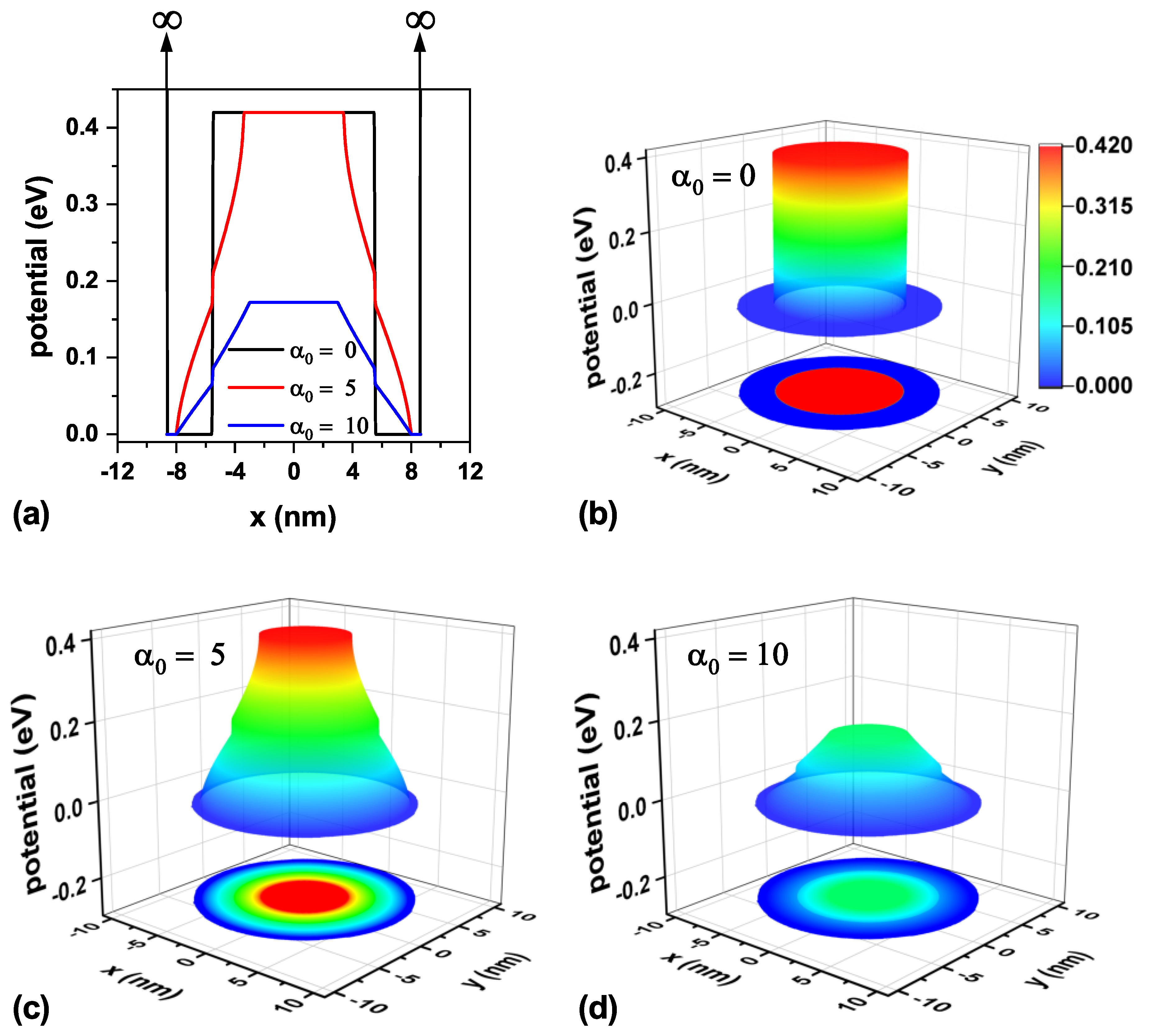
Figure 4.
Representation of the electron confinement potential on a transverse section at the base of the nanostructure, nm, for the CdTe/CdSe core/shell TCQD with geometrical parameters nm, nm, nm, and nm considering three different values of the laser parameter as (a) a 2D plot of the potential profile, and a 3D view and 2D projection of the confinement potential: (b) in the absence of ILF, (c) with nm, and (d) with nm.
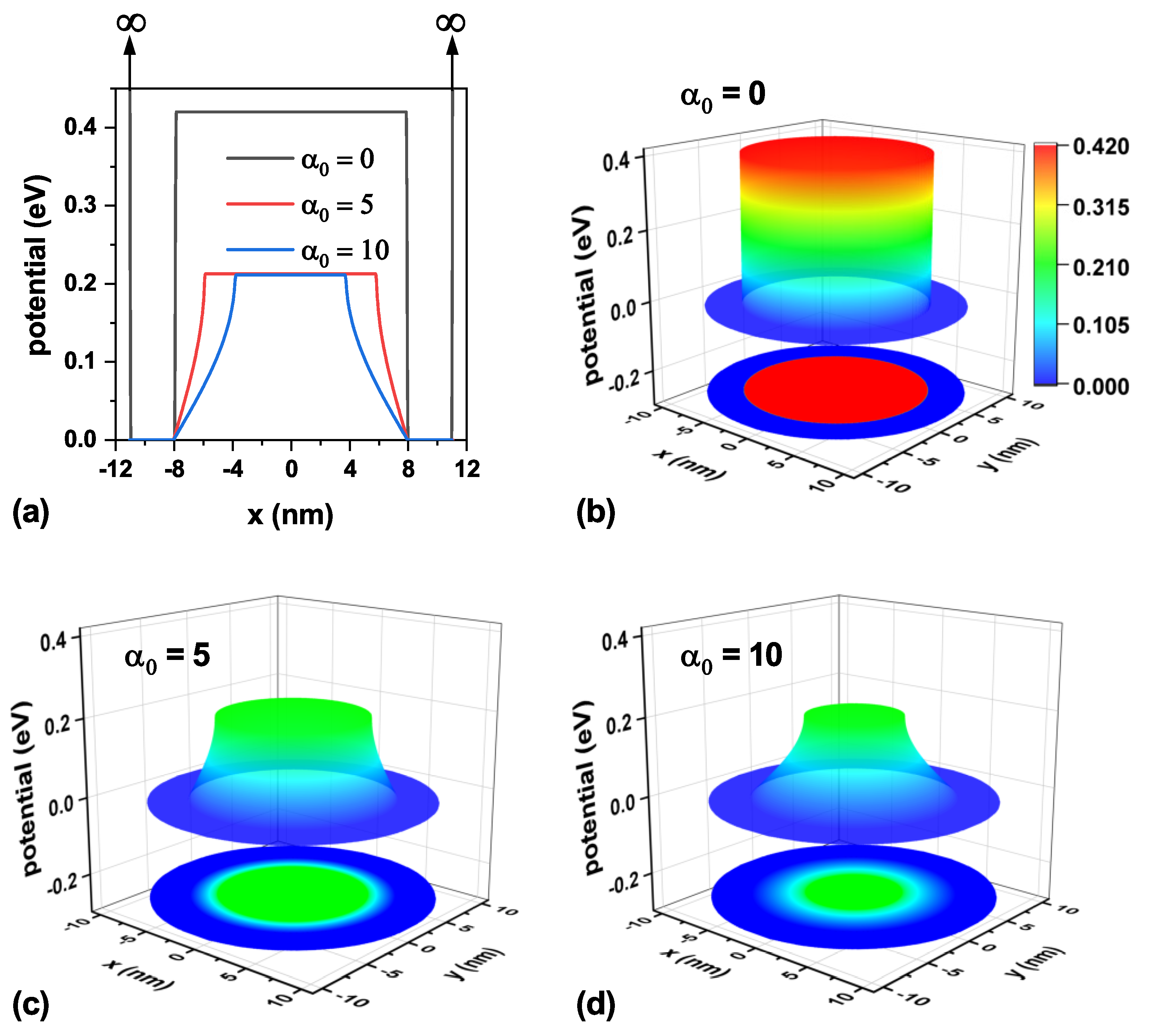
Figure 5.
Energy spectrum of the CdTe/CdSe core/shell TCQD with geometrical parameters nm, nm, nm, and nm as a function of the laser parameter for different values of the quantum number, l. Solid lines correspond to the axisymmetric 2D model and dotted lines are obtained from a 3D model. The ground-state electron probability density for three values of the laser parameter is also depicted. The calculations correspond to .
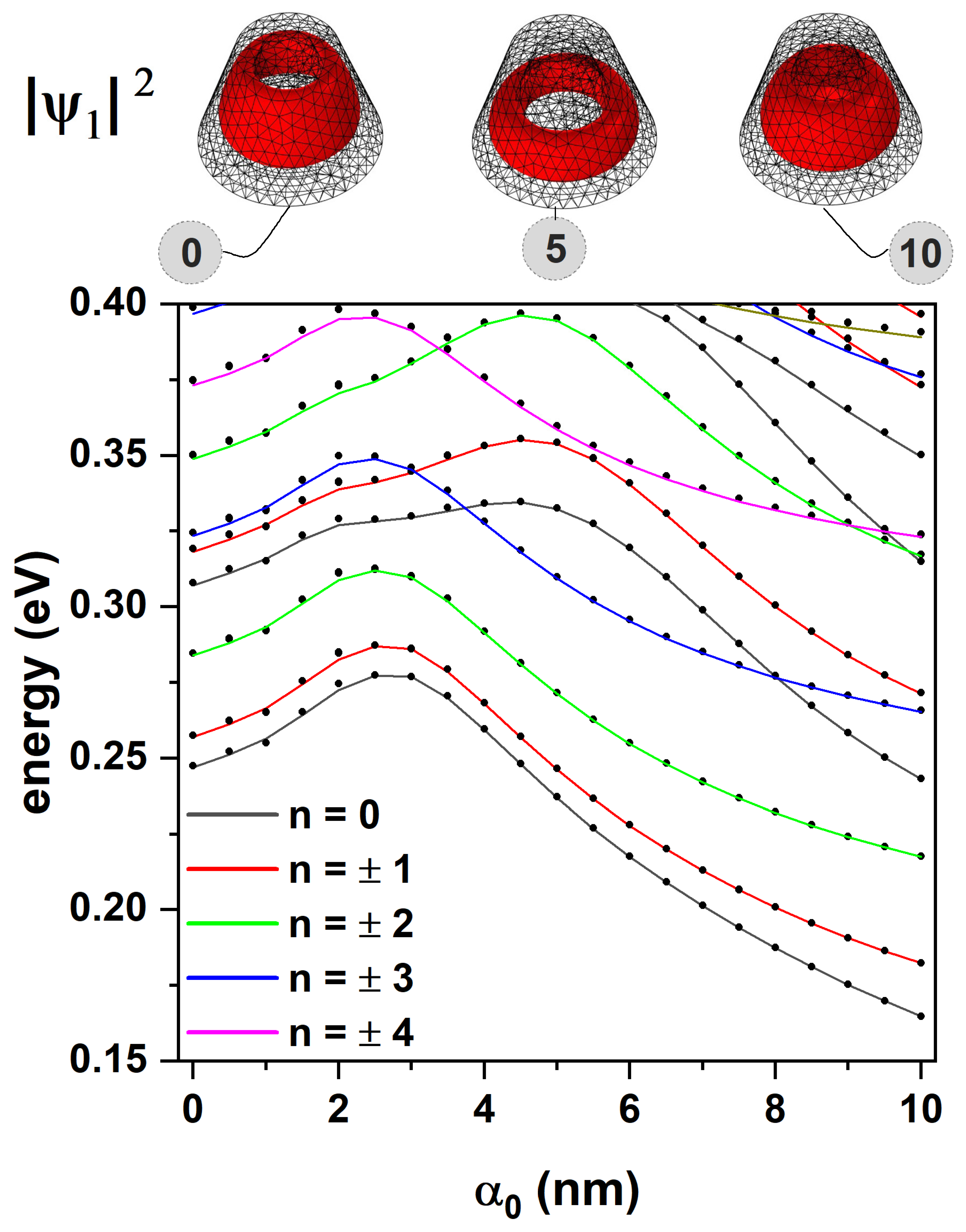
Figure 6.
Energies of the three low-lying electron states in the CdTe/CdSe core/shell TCQD are presented as functions of the externally applied electric field for three different values of the laser parameter: (a) , (b) , and (c) nm. In (d), the electron ground-state probability densities are shown for three different electric field values and three laser parameter strengths. Dashed lines in (d) are depicted to visualize the changes with the electric and laser fields. The geometric parameters are fixed as nm, nm, nm, and nm.
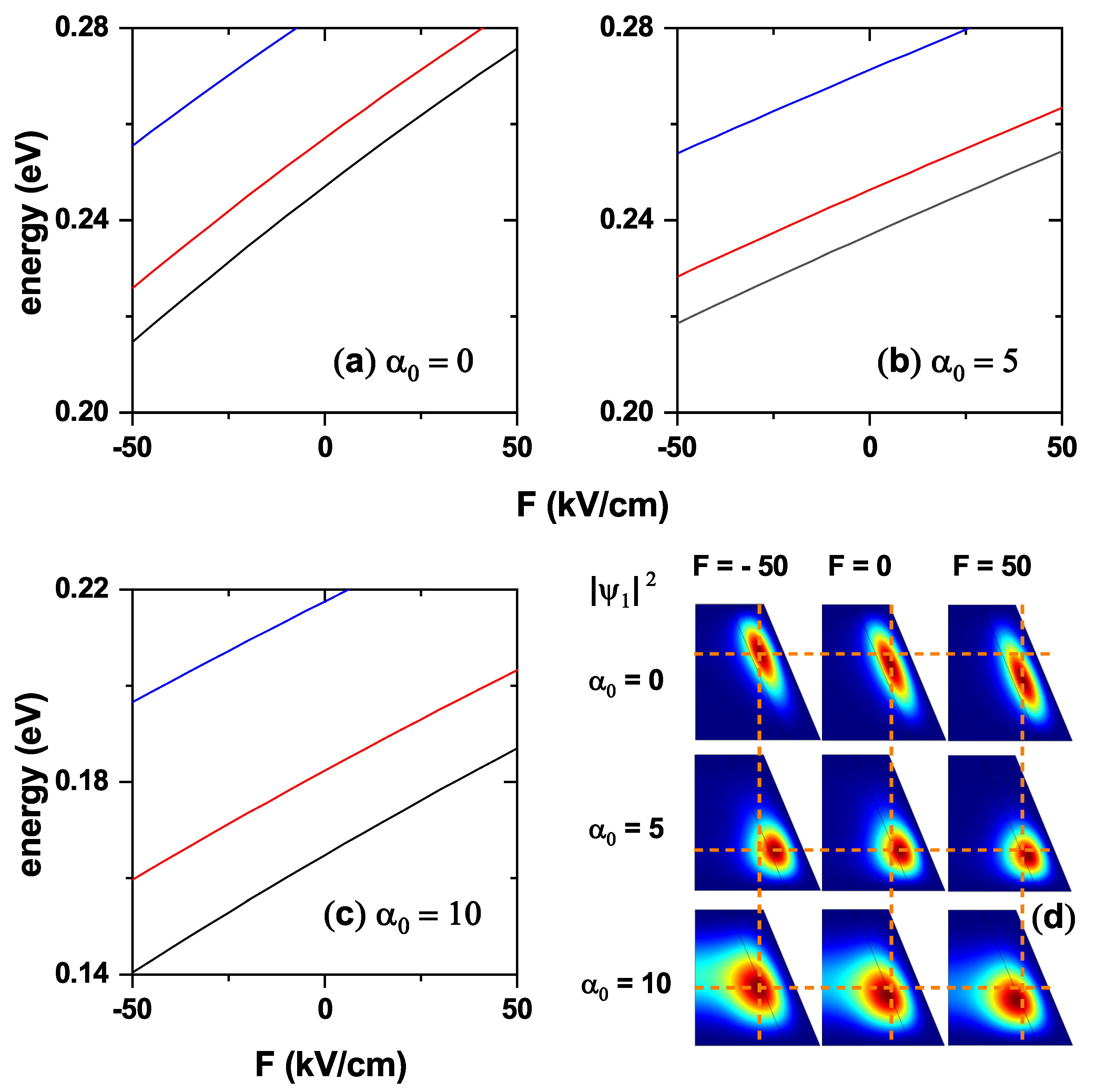
Figure 7.
-projection of the hole confinement potential in a CdTe/CdSe core/shell TCQD associated with (a) , (b) nm, (c) nm, and (d) nm. The geometrical parameters of the structure are kept constant with values nm, nm, nm, and nm.
Figure 7.
-projection of the hole confinement potential in a CdTe/CdSe core/shell TCQD associated with (a) , (b) nm, (c) nm, and (d) nm. The geometrical parameters of the structure are kept constant with values nm, nm, nm, and nm.
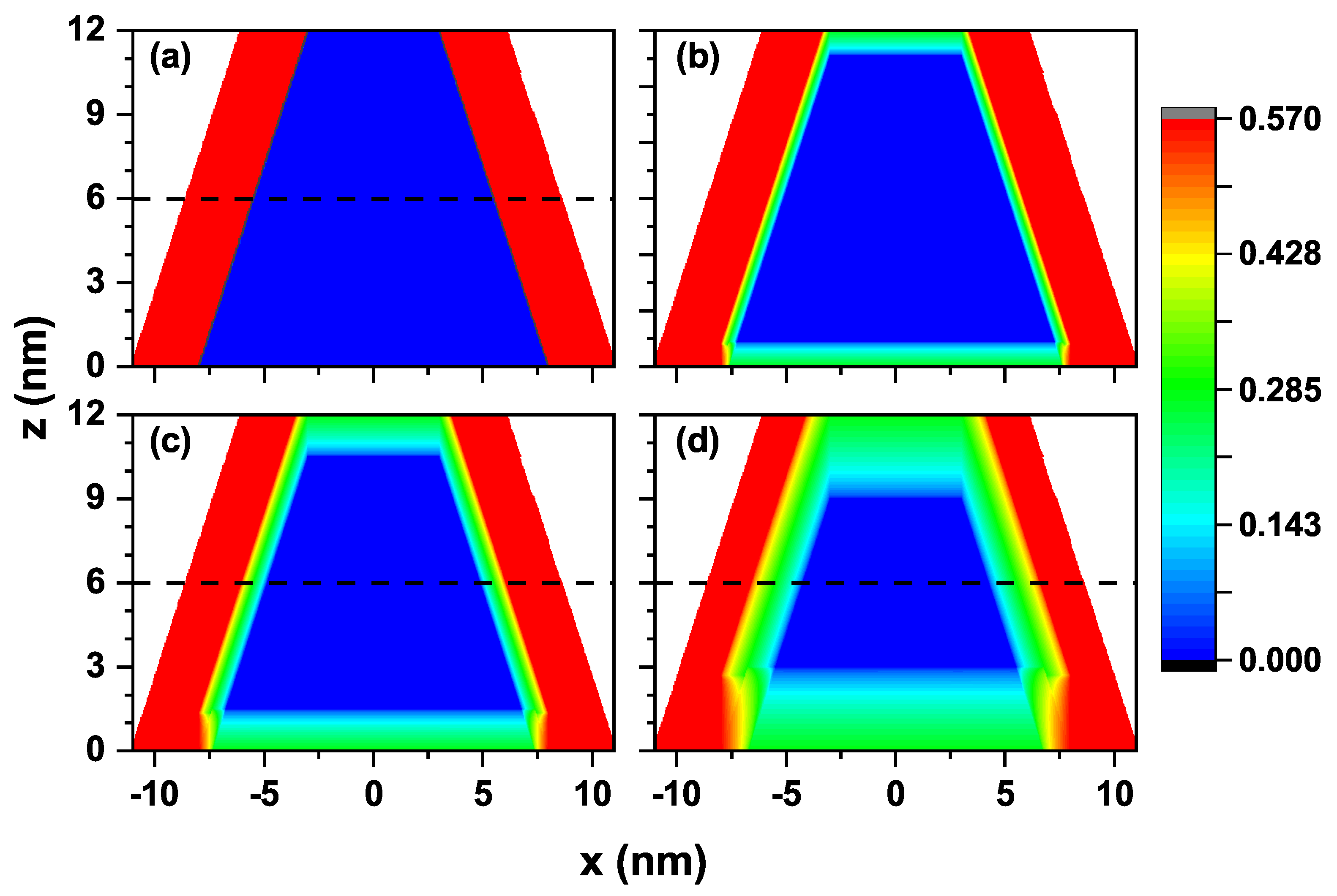
Figure 8.
Representation of the hole confinement potential on a transverse section at half the nanostructure height, nm, for the CdTe/CdSe core/shell TCQD with geometrical parameters nm, nm, nm, and nm considering three different values of the laser parameter as (a) a 2D plot of the potential profile, and a 3D view and 2D projection of the confinement potential: (b) , (c) with nm, and (d) with nm.
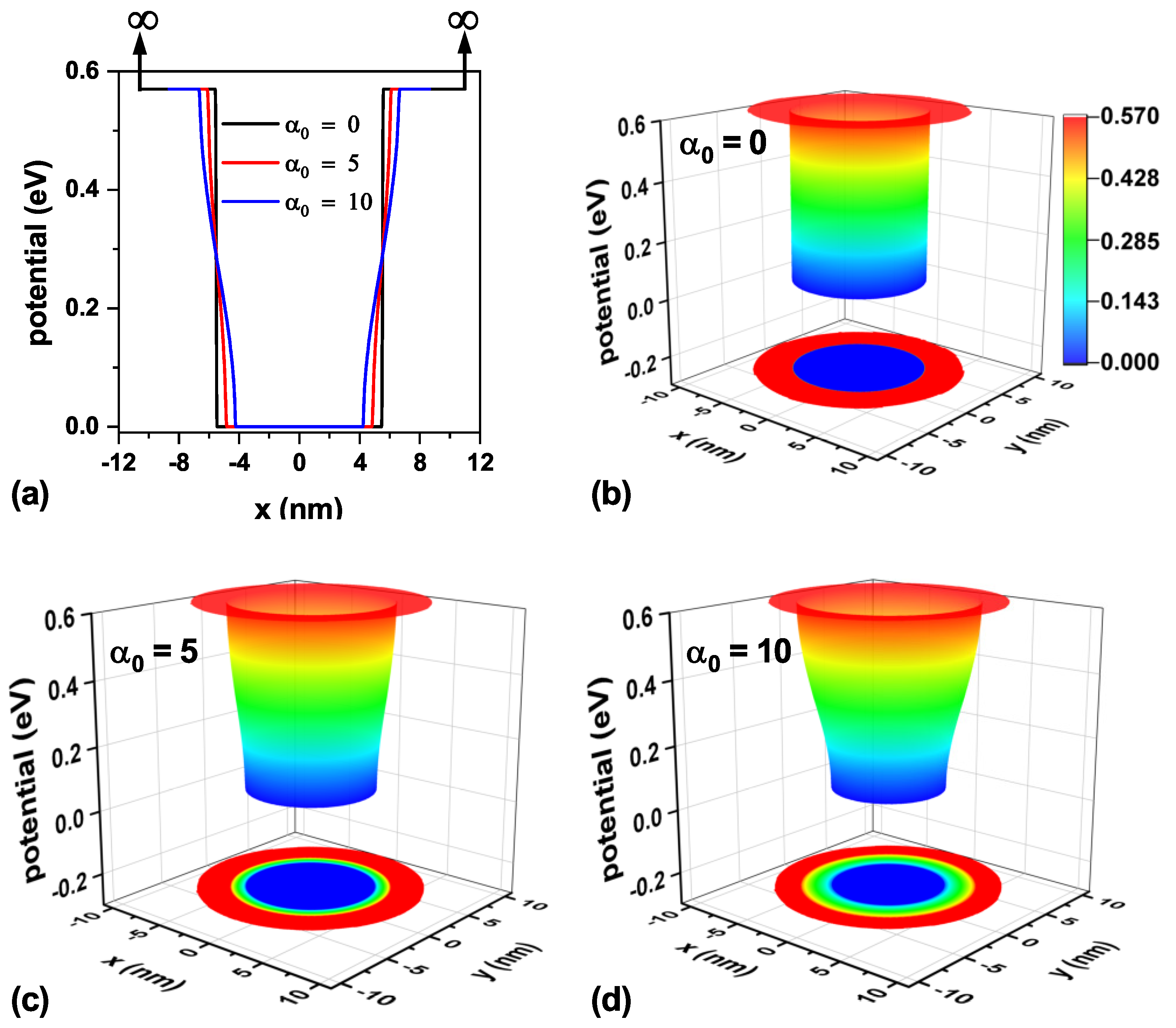
Figure 9.
Representation of the hole confinement potential on a transverse section at the base of the nanostructure, nm, for the CdTe/CdSe core/shell TCQD with geometrical parameters nm, nm, nm, and nm considering three different values of the laser parameter as (a) a 2D plot of the potential profile, and a 3D view and 2D projection of the confinement potential: (b) , (c) with nm, and (d) with nm.
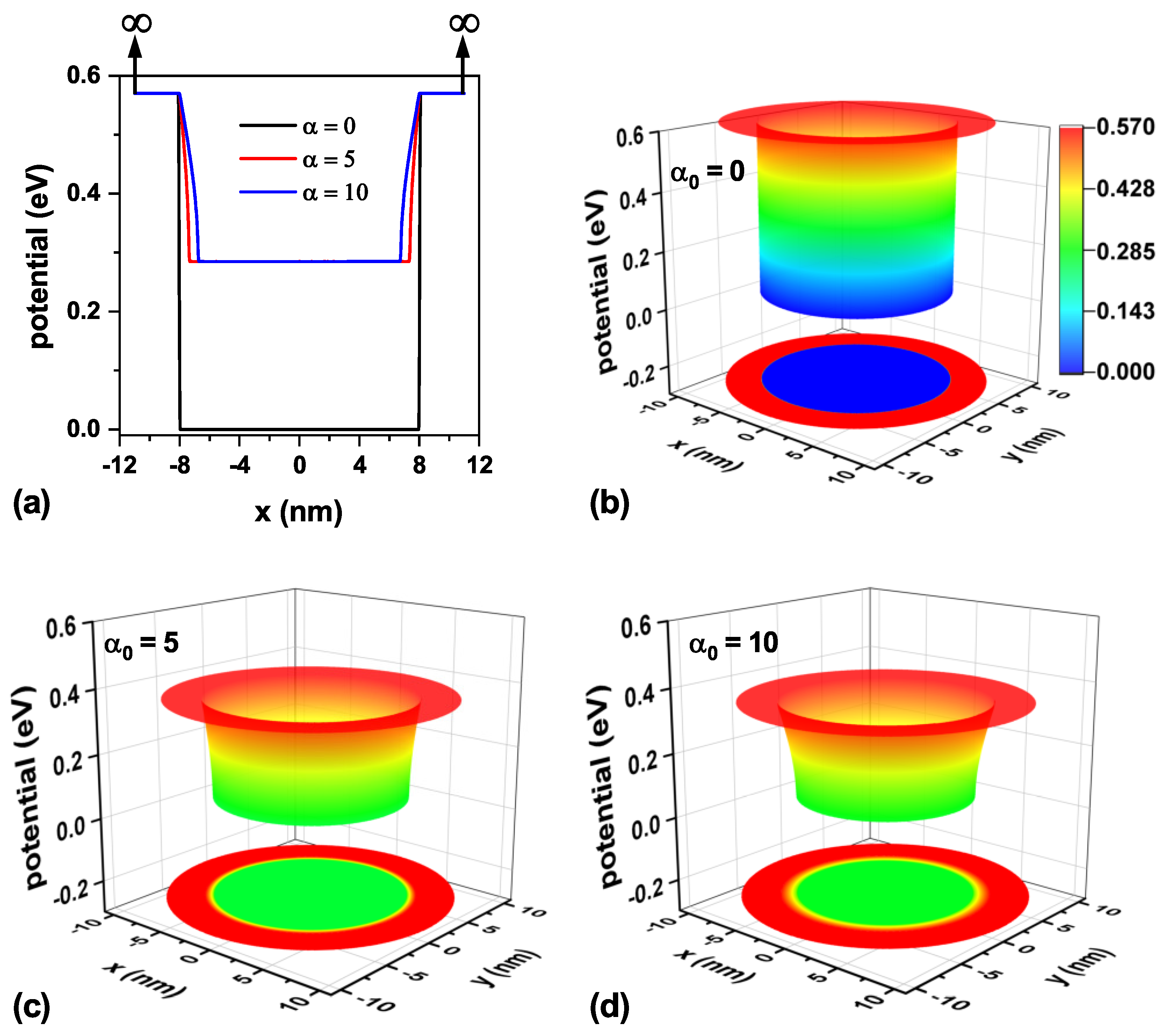
Figure 10.
Energy spectrum of the CdTe/CdSe core/shell TCQD with geometrical parameters nm, nm, nm, and nm as a function of the laser parameter for different values of the quantum number, l. Solid lines correspond to the axisymmetric 2D model, and dotted lines are obtained from a 3D model. The ground-state hole probability densities for three values of the laser parameter are also depicted. Calculations correspond to .
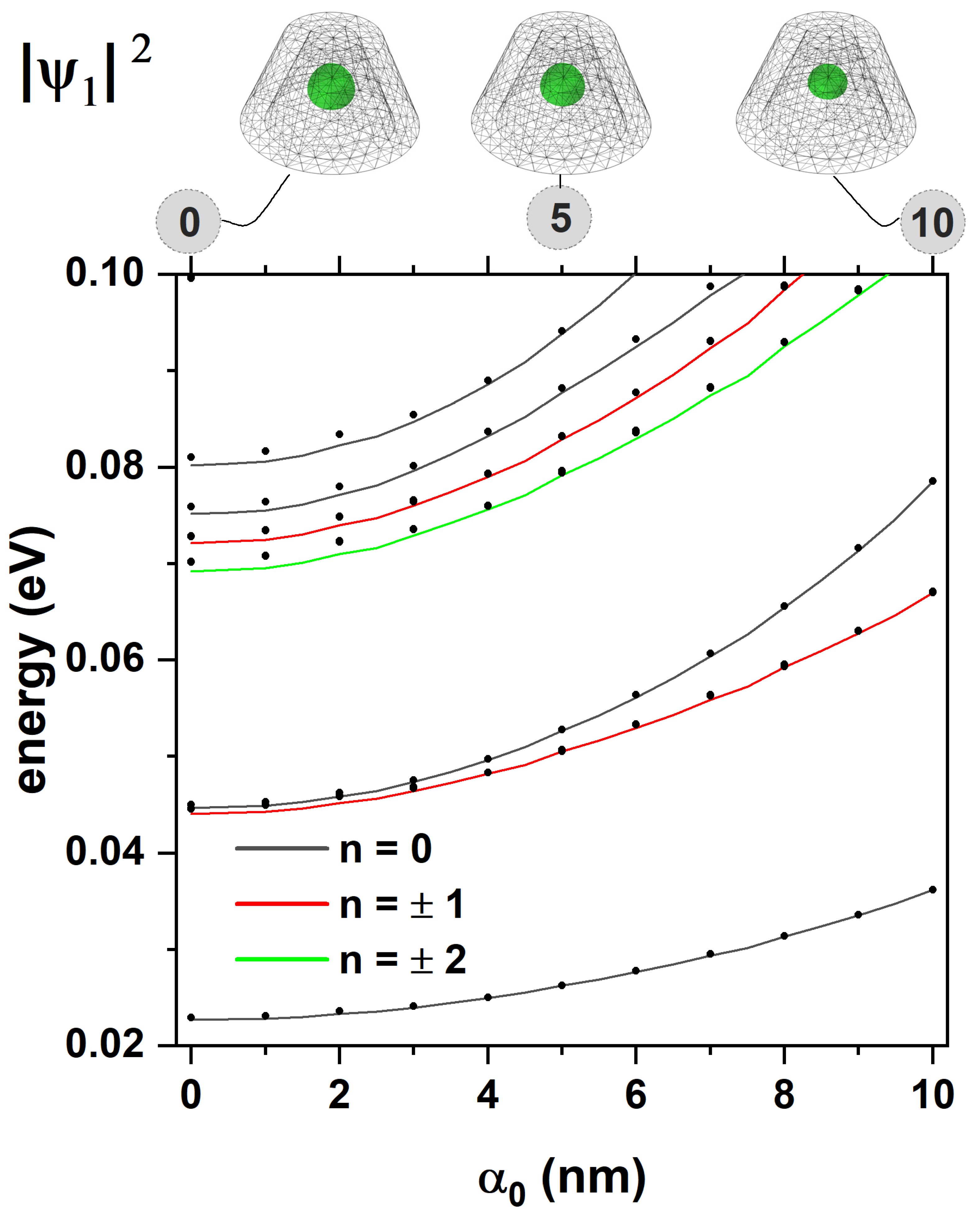
Figure 11.
Energies of the first low-lying low states in the CdTe/CdSe core/shell TCQD are presented as functions of the externally applied electric field for three different values of the laser parameter, (a), (b), and nm (c). In (d) are depicted the hole ground state probability density for different electric field values and the three analyzed laser parameters. Dashed lines in (d) visualize the changes in the electric and laser fields. The geometric parameters are fixed as nm, nm, nm, and nm.
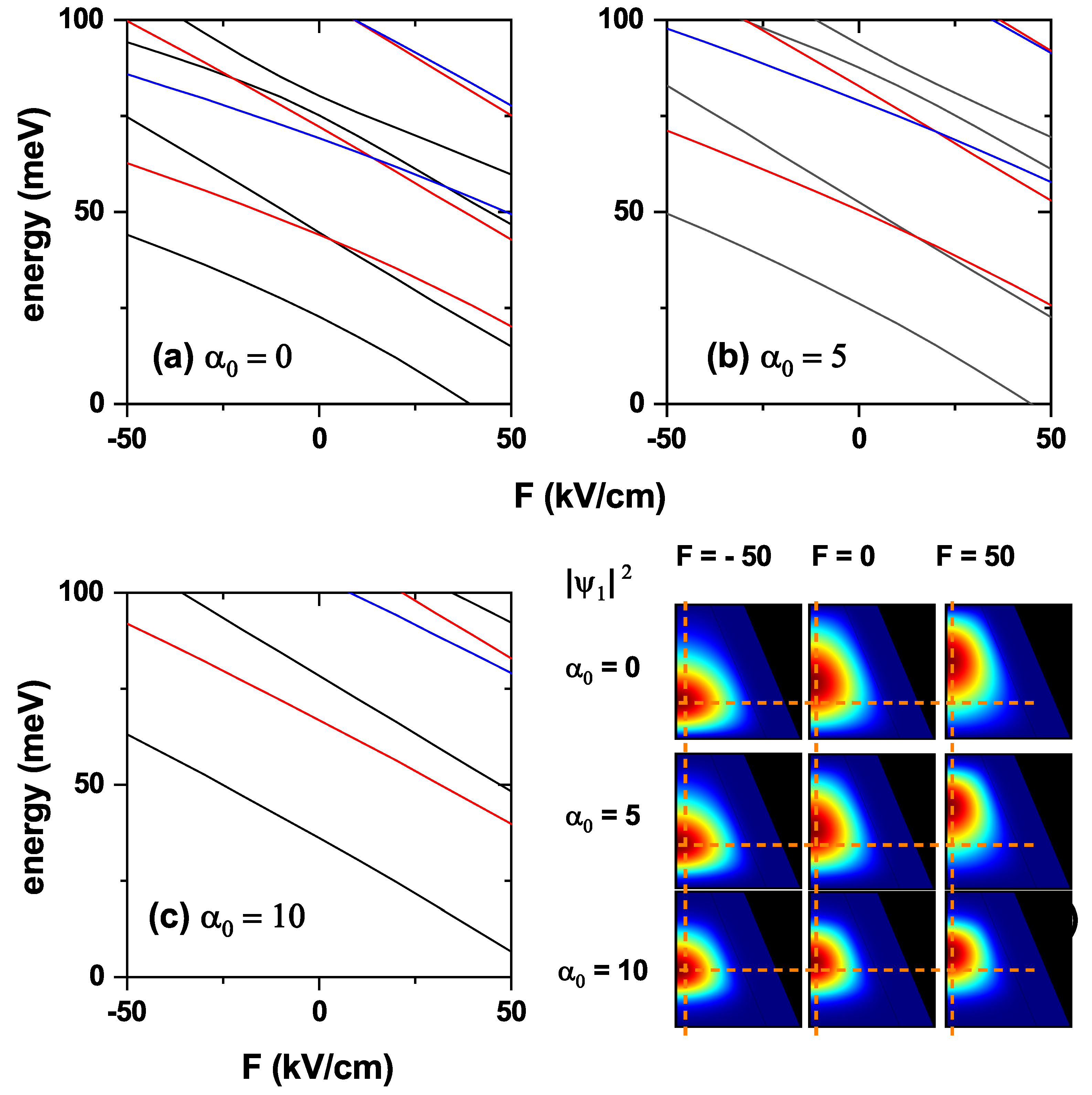
Figure 12.
Electron–hole Coulomb energy as a function of laser parameter for three fixed values of the electric field, 0, 50 kV/cm, and kV/cm in the CdTe/CdSe core/shell TCQD with The geometric parameters fixed as nm, nm, nm and nm.
Figure 12.
Electron–hole Coulomb energy as a function of laser parameter for three fixed values of the electric field, 0, 50 kV/cm, and kV/cm in the CdTe/CdSe core/shell TCQD with The geometric parameters fixed as nm, nm, nm and nm.

Disclaimer/Publisher’s Note: The statements, opinions and data contained in all publications are solely those of the individual author(s) and contributor(s) and not of MDPI and/or the editor(s). MDPI and/or the editor(s) disclaim responsibility for any injury to people or property resulting from any ideas, methods, instructions or products referred to in the content. |
© 2025 by the authors. Licensee MDPI, Basel, Switzerland. This article is an open access article distributed under the terms and conditions of the Creative Commons Attribution (CC BY) license (http://creativecommons.org/licenses/by/4.0/).
Copyright: This open access article is published under a Creative Commons CC BY 4.0 license, which permit the free download, distribution, and reuse, provided that the author and preprint are cited in any reuse.


