
Submitted:
12 June 2025
Posted:
13 June 2025
You are already at the latest version
Abstract
This research presents the development and management principles of mobile resonant electrical systems designed for high-voltage generation, intended for non-destructive diagnostics of insulation in high-power electrical equipment. The core of the system is a series inductive-capacitive (LC) circuit characterized by a high qual-ity (Q) factor and operating at high frequencies, typically in the range of 40–50 kHz or higher. Practical implementations of the LC circuit with Q-factors exceeding 200 have been achieved using advanced materials and configurations. Specifically, ceramic ca-pacitors with a capacitance of approximately 3.5 nF and Q-factors over 1000, in con-junction with custom-made coils possessing Q-factors above 280, have been employed. These coils are constructed using multi-core, insulated, and twisted copper wires of the Litzendraht type to minimize losses at high frequencies. Voltage amplification within the system is effectively controlled by adjusting the current frequency, thereby max-imizing voltage across the load without increasing the system's size or complexity. This frequency-tuning mechanism enables significant reductions in the weight and dimensional characteristics of the electrical system, facilitating the development of compact, mobile installations. These systems are particularly suitable for on-site testing and diagnostics of high-voltage insulation in power cables, large rotating machines such as turbogenerators, and other critical infrastructure components. Beyond insula-tion diagnostics, the proposed system architecture offers potential for broader applications, including the charging of capacitive energy storage units used in high-voltage pulse systems. Such applications extend to the synthesis of micro- and nanopowders with tailored properties and the electrohydropulse processing of materials and fluids. Overall, the research demonstrates a versatile, efficient, and portable solution for ad-vanced electrical diagnostics and energy applications in the high-voltage domain.
Keywords:
mobile resonant systems
; high-voltage generation
; non-destructive diagnostics
; dielec-tric strength assessment
; field testing technology
; insulation condition monitoring
1. Introduction
Facilities of critical infrastructure in Ukraine in the war and post-war periods makes it urgent to solve the problem of mobile monitoring of the technical condition of its electrical insulation and determine the conditions for its further use. For international certification of cable and wire products (CWPs) with cross-linked polyethylene (XLPE) insulation, it is necessary to test them with increased sinusoidal voltage up to 500 kV according to the national standard [1]. There is only one electrical system (ES) in Ukraine based on a series resonant inductive-capacitive circuit (ICС) for such testing. The currents with a frequency of 50 Hz are generated in the ES [2]. The Q-factor of such a system is regulated in the range from 20 to 40. To implement such a Q-factor, electrical equipment from leading companies in Europe and the USA was used, in particular, two low-frequency inductors weighing 18 tons each from the company Hipotronics (USA) [2]. The ES is connected to a 380 V line voltage of a three-phase industrial network with a frequency of 50 Hz, and to increase the voltage to 500 kV, in addition to the resonant ICC, a Paschen's step-up autotransformer and an additional single-phase transformer are used. A similar structure is found in the ESs of such well-known manufacturers of high-voltage CWPs as ABB (Germany), Nexans (France), Bruggkabel (Belgium), Sumitomo Electric (Japan) and Okonite (USA) [2]. But the inductors and transformers of such ESs are designed to carry low-frequency high currents and have a limited Q-factor (less than 40) as well as large mass and dimensions. Such circumstances do not allow the use of such ESs for mobile monitoring of the insulation of power facilities at their locations, which is necessary to ensure rapid diagnostics of high-voltage insulation of power facilities in Ukraine in this wartime.
It should be noted that studies of the properties of resonant-type ESs using ICCs with low-frequency sinusoidal currents were carried out in the 20th century by many scientists, in particular at the Institute of Electrodynamics of the NAS of Ukraine (Kyiv) under the leadership of O.M. Milyakh and I.V. Volkov [3]. However, the main research was aimed at determining the optimal conditions for stabilizing low-frequency current (mainly 50 Hz) in the load when changing its electrical resistance. Moreover, the famous French electrical engineer Paul Bouchereau paid attention to the conditions for stabilizing the sinusoidal current in the ICC load back in 1891.
Further studies of the stabilizing properties of low-frequency resonant ICCs substantiated the effectiveness of their use for powering welding arcs, speed regulation of DC drives, charging batteries and storage capacitors. In these powerful resonant ESSs with serial ICCs, the high sinusoidal currents that do not depend on the electrical resistance of the load were generated in the load [4]. The frequency of these currents was considered unimportant. Moreover, to increase the frequency, it would be necessary to create additional powerful devices – semiconductor frequency converters, essentially rectifiers and inverters, which significantly complicated the implementation of constant sinusoidal currents of increased frequency in the load [5]. In addition, the implementation of ultra-high Q-factors in ICCs would correspond to their idling modes, which were considered emergency and unacceptable modes in [3,4].
The development of non-destructive diagnostic methods for high-voltage power equipment insulation demands the introduction of advanced mobile resonant systems that offer improved operational flexibility, accuracy, and safety [6]. These systems must be capable of generating high-voltage test signals under real-world conditions, including unstable network parameters, asymmetric voltage, and varying load profiles. In this context, the study by Seheda et al. [7] plays a foundational role. It presents a detailed mathematical model for managing wave processes in three-winding transformers while considering the main magnetic flux – an essential factor in achieving resonance conditions with high precision. Their findings contribute significantly to the modeling and control of mobile high-voltage systems operating in environments such as the mining industry.
The research provides valuable insights into the dynamic behavior of asynchronous motors operating under conditions of voltage asymmetry, which is a common phenomenon in real-world electrical networks [8]. Such asymmetry can significantly affect the performance and stability of mobile high-voltage diagnostic systems, especially when deployed in complex industrial environments [9]. Understanding these dynamic interactions is essential for preventing resonance mismatches, minimizing electromagnetic disturbances, and ensuring accurate test conditions [8,9,10]. Moreover, it plays a critical role in reducing the risk of insulation overstress and equipment malfunction during on-site field diagnostics.
Another important methodological contribution examines the hydrodynamics of translational–rotational motion within a vortex heat generator, offering a detailed analysis of fluid behavior under dynamic conditions [11]. Although physical application differs from high-voltage electrical systems, the mathematical modeling of incompressible gas flow presents valuable analogies for analyzing energy transfer mechanisms [12]. These analogies can be applied to the study of heat dissipation, dynamic stability, and internal energy distribution in compact high-voltage generation devices. As such, the research enriches the theoretical framework for improving the efficiency and reliability of mobile resonant systems used in non-destructive diagnostics [11,12,13].
The study explores the influence of voltage reserve on the behavior of active power compensators in mining applications, where stable power quality is critical for continuous operations [14]. It highlights how fluctuations in voltage reserve can impact the efficiency and responsiveness of compensation systems, particularly under varying load conditions [15]. This is directly relevant to the deployment of mobile resonant high-voltage systems, which often operate in energy-sensitive and infrastructure-constrained environments [15,16]. The findings underscore the necessity for diagnostic equipment to adaptively manage energy flow and maintain voltage stability to ensure accurate and safe testing procedures.
The cultural and systemic implications of power usage are addressed through a discussion on fostering a culture of frugal energy consumption within the broader context of social energy security [17]. This research emphasizes the importance of responsible energy use at both individual and institutional levels, highlighting how behavioral and policy-driven changes contribute to overall system sustainability. Although the topic may appear tangential to technical diagnostics, it reinforces the strategic direction of developing mobile high-voltage diagnostic technologies that support energy efficiency [18]. Such systems help prevent equipment faults, reduce unnecessary downtime, and optimize energy use in field operations [19]. Ultimately, this alignment with global energy-saving objectives enhances both the environmental and operational sustainability of power infrastructure.
The interdisciplinary perspective offered on ecosystem functionality and legal frameworks for environmental restoration highlights a broader trend toward integrated, systemic thinking across scientific domains [20]. This approach emphasizes the need to consider complex interdependencies within systems, whether they involve natural ecosystems or engineered infrastructures [19,21]. In the field of electrical diagnostics, a similar paradigm shift is occurring, as mobile resonant systems increasingly replace traditional bulky and stationary equipment. These advanced tools offer greater flexibility, energy efficiency, and real-time data management, enabling more responsive and sustainable diagnostic practices [19,21,22]. The referenced study reinforces the value of cross-sector innovation in addressing multifaceted challenges through adaptive, scalable solutions [23]. Such convergence of ecological and technological systems thinking underlines the importance of holistic strategies in both environmental policy and advanced electrical engineering [19,21,22,23,24].
The management of mobile resonant electrical systems for high-voltage generation is essential in advancing non-destructive diagnostics of power equipment insulation, which is critical for ensuring the reliability and safety of energy infrastructure. Traditional diagnostic methods often lack portability and precision in detecting early-stage insulation degradation [25]. This research addresses the urgent need for compact, controllable, and efficient resonant systems capable of generating high-voltage test signals on-site, enabling timely maintenance decisions, reducing equipment failure risks, and extending asset lifespans. By optimizing these systems' operational parameters and control mechanisms, the study supports the development of more responsive and adaptable diagnostic tools in modern power networks.
2. Materials and Methods
The study employed a mobile resonant electrical system (MRES) tailored for high-voltage generation in the non-destructive diagnostics of power equipment insulation. The MRES setup included a high-voltage step-up transformer (up to 250 kV), a variable inductive reactor for resonance tuning, and a digital control cabinet with microprocessor-based regulation. These components were integrated with precision measuring equipment, voltage dividers, current sensors, and capacitive probes, to ensure accurate monitoring during diagnostics [2,26]. The system was designed to excite the resonant frequency of the test object's capacitive load, typically representing components such as transformer bushings, GIS elements, and high-voltage cables. Resonant conditions were confirmed using voltage rise curves and phase displacement analysis, following standard methods described in IEC 60060-3 [27].
To enhance automation and safety, a real-time control algorithm was developed and implemented on an STM32 microcontroller with embedded RTOS. The algorithm regulated the excitation voltage, tracked feedback loops for voltage and current, and executed protective shutdowns upon detecting faults such as overvoltage or breakdown [28]. This smart regulation ensured optimal resonant behavior, even under fluctuating load conditions. The testing protocol included gradual voltage ramping, partial discharge detection via ultra-wideband (UWB) sensors, and dielectric loss measurement using a Schering bridge. These methods are consistent with established high-voltage testing practices outlined in IEEE Std 4-2013 [29].
Simulation and validation were performed using MATLAB/Simulink and PSCAD/EMTDC to model the dynamic behavior of the MRES and predict system response under various fault scenarios. These simulations were essential to verify the stability of the control loop and the resonance characteristics of the system. Field testing was conducted at operational substations (110–330 kV) under scheduled maintenance conditions, ensuring safe application of diagnostic voltage levels [30]. All testing adhered to national and international standards to maintain consistency and technical credibility. Similar approaches to resonant testing have been validated in other works focused on mobile HV systems and on-site diagnostics [30,31].
2.1. The Mathematic Apparatus for Non-Destructive Diagnostics of Power Equipment Insulation
The mathematical modeling of the mobile resonant electrical system (MRES) is grounded in the theory of series resonance in RLC circuits. At resonance, the inductive reactance XL = ωL equals the capacitive reactance XC = 1/ωC, resulting in a purely resistive impedance and a maximal voltage rise across the capacitive load—typically, the insulation of high-voltage equipment [2,32]. The resonant frequency is determined by the expression:
where: f0 is the natural resonant frequency (Hz), L is the inductance (H), and is the capacitance (F) of the test object [32]. The voltage magnification at resonance is characterized by the quality Q-factor, which also defines the system’s amplification capability:
where R represents the series resistance, and Uin, Uout are the input and output voltages, respectively [27]. The is the resonant angular frequency, equal to 2πf0.
To maintain optimal resonant conditions during field operation, a feedback control algorithm was developed using digital control theory principles [33]. The primary indicator for resonance was the minimization of the phase angle φ between voltage and current (φ → 0), which was tracked in real time via digital signal processing [29]. The excitation source was regulated through a PID controller, whose response was governed by the control law:
where u(t) is the output control action, e(t) is the deviation from the desired voltage, and Kp, Ki, and Kd are the respective proportional, integral, and derivative gains. This controller was tuned to respond to fluctuations in the capacitive load due to environmental or equipment-related variability [28,34]. Simulations were carried out using MATLAB/Simulink and PSCAD/EMTDC environments, enabling validation of transient response, resonance tracking, and overall system stability under different operational scenarios [31,35].
2.2. Optimization of Resonant Impulse Capacitive Circuit-Based Electrical Systems
The advancement of pulsed power engineering, particularly in the context of utilizing powerful pulsed discharges in loads, has highlighted the need to improve the principles for designing and optimizing electrical systems (ESs) based on impulse capacitive circuits (ICCs) [5,36,37]. However, the design principles for resonant-type ESs have not been sufficiently developed to support ultra-high-quality Q-factors and, consequently, the generation of high voltages within ICCs without relying on high-voltage transformers. Progress in pulsed technologies has focused on developing novel methods for electrophysical and electrochemical treatment of materials [38,39,40,41], as well as refining the general theoretical framework for charging and discharging capacitive energy storage devices (ESDs) [42]. Notably, the method of difference equations has proven effective in accounting for the stochastic variation of load resistance during transient processes in electrical discharge installation (EDI) circuits [43]. Furthermore, in the design of EDIs for producing electro-eroded micro- and nanopowders with unique properties [38,39], it is not only beneficial to use banks of parallel-connected capacitors, but also to consider the redistribution of energy among them, depending on their individual parameters and voltage levels [44].
Subsequent research [45,46] demonstrated that ESDs can be charged to high voltages using resonant-type ESs without the need for step-up transformers. High-voltage EDIs were developed for electrospark treatment of carbon-containing gases such as propane-butane, enabling the synthesis of nanocarbon materials with exceptional characteristics [45].
Currently, during the ongoing wartime conditions in Ukraine, the systematic destruction of critical energy infrastructure by the Russian aggressor has intensified. As a result, a primary focus of scientific research has shifted toward developing mobile solutions for monitoring the technical condition of high-voltage insulation in the most vulnerable components of the energy system. These include power transmission cables rated up to 35 kV [47] and large electrical machines such as nuclear power plant turbogenerators, along with other high-power asynchronous and synchronous machines [48,49,50]. Insulation diagnostics for such equipment can be performed by monitoring leakage currents under elevated voltage and by measuring partial discharge activity either at constant frequency and variable voltage, or vice versa [51]. Therefore, the development of mobile, autonomous ESs capable of rapid high-voltage insulation diagnostics in the field has become a strategic priority. These systems must feature compact size, low weight, enhanced fault resistance during insulation breakdown, and a precisely controllable high-Q ICC configuration.
3. Results of the Research
The main objective of this study was to develop principles for constructing mobile high-voltage transformerless ESs using serial high-quality inductive-capacitive circuits and high-frequency sinusoidal currents, the targeted frequency regulation of which can provide a multiple increase in alternating voltage on the load of the ESs.
The principles of constructing high-voltage ESs of the resonant type, which can generate output voltages of the order of tens of kV, are based on the following approaches:
1. Increasing the resonant current frequency using equations (1, 2) in the ICC by a thousand times (compared to the network frequency of 50 Hz) and purposeful regulation of the frequency of this current will provide the highest Q-factor of the ICC (QICC) and, accordingly, the highest voltage on the ES load and will lead to the following desired results:
– speed of control and parametric stabilization of ES load modes will increase;
– the reactance of the coil (XL= L, where L is its inductance value) will proportional increase by a thousand times;
– the magnitude of the current and active power losses in the coil will decrease;
– the energy that accumulates in the reactive elements of the ICC (WL = 0.5 LIL2 and
WС = 0.5 СUС2) and destroys the insulation during its electrical breakdown will decrease;
– the Q-factor (2) of the coil will increase many times, since its active resistance RL does not grow as fast as the reactance XL = 2πf L, especially at current frequencies f < 10 kHz, at which the effect of current displacement to the surface is insignificant;
– wide-range regulation (several times) of the output voltage ES can be achieved by changing the current frequency in the ICC by only a few %;
2. Manufacturing of ICC coils from multi-core insulated, tightly twisted thin copper wires of the "litzendraht" type, the use of which ensures:
– significant (tens of times) increase in the Q-factor (2) of the coil QL = 2πf L/RL at a current frequency f > 10 kHz;
– increase the voltage on the coil and capacitor in QL times when resonant currents flow in the ICC, arising at XL = 2πf L = (2πf С) – 1;
– decrease in voltage (and, accordingly, in current) in the load by QICC times with a rapid decrease in its electrical resistance to almost zero (in particular, during an electrical breakdown of the insulation).
Under the condition of voltage resonance in the series ICC of the experimental resonant ES developed by the authors, the output voltage on the load (connected to one of the reactive elements of the ICC) was proportional to the Q-factor ICC (the QICC of this ES was more than 250). And in emergency modes (close to a short circuit of the load), the voltage and current in the load quickly (less than half the period of the resonant current in the ICC) parametrically decreased by QICC times.
In high-voltage resonant systems, it is desirable to use air-sectioned inductors, since sectioning increases the operating voltage of such a coil and reduces its own capacitance. In these studies, the authors used 2 coils: the first of which had 4 sections, an inductance of 23.2 mH and an active resistance of 12.7 Ohm at an operating voltage of up to 35 kV, and the second coil had 8 sections, an inductance of 186.5 mH and an active resistance of 34.7 Ohm at an operating voltage of up to 50 kV. At current frequencies from 5 to 40 kHz, both coils worked well. The coil sections were made with a square cross-section and with a ratio of the average diameter to the length of the coil equal to approximately 3. And the Q-factor of modern ceramic capacitors used in ICC was several thousand. It should be noted that increasing the frequency of currents in ICC with an unchanged average power ES leads to the transfer of energy to the load in significantly smaller portions, which enhances the protection of ES.
A multiple increase in voltage to 40-70 kV at the output of resonant-type ESs, whose ICCs have Q-factors of more than 250, is not an emergency mode, since such ESs are aimed at measuring leakage currents (up to 0.2 mA) of high-voltage insulation of power cables, turbogenerators, and other large electrical machines. The operating mode of the ESs and ICCs is essentially very close to the so-called idle mode.
The design principles proposed by the authors differ significantly from the known ones, the purpose of which was to create sufficiently powerful ESs from ICCs [3,4,5,6,7,8,9,10,11,12] to stabilize high low-frequency sinusoidal currents in the load, and according to which the implementation of ultra-high Q-factors (more than 250) is an emergency mode, in which the power consumption of the input sinusoidal voltage source will be extremely high.
The losses of electric power in the electric circuits of the proposed ES and its weight and dimensions will be significantly (several times) reduced. It becomes possible to create a mobile ES (weight up to 5 kg) and an autonomous one with power supply from batteries.
The structural diagram of the power part of the experimental sample of such a high-voltage resonant-type ES is presented in Figure 1.
The ES can be connected to a 220 V AC voltage source, which can be a regular power supply network or an autonomous power supply system.
The power part of the ETS consists of:
– the input rectifier, at the output of which the voltage is doubled;
– the high-frequency half-bridge voltage inverter, generating voltage with a frequency of 5–40 kHz;
– the resonant LrCr circuit;
– the high-voltage rectifier, at the output of which a load (an insulation sample of the cable being diagnosed) is connected through a protective spark gap.
By connecting the developed electrical system (ES) to a standard 220 V AC power supply and tuning the frequency of the current flowing through the impulse capacitive circuit (ICC), it becomes possible to achieve high-voltage generation in the range of 40–75 kV at the ES output. This high-voltage output is obtained without the use of traditional step-up transformers, due to the resonance effect in the ICC, which enables significant voltage magnification. The ability to precisely regulate the excitation frequency allows for efficient adaptation to varying capacitive loads, ensuring optimal performance in field diagnostics. Figure 2 presents a detailed structural diagram of the power section of the experimental ES, illustrating the main functional components and their interconnections.
This architecture of the circuit is determined, firstly, by the fact that one of the inverter outputs has direct electrical contact with neutral and ground. Therefore, to ensure the EC operating modes, both the resonant capacitor Cr and the load (insulation sample) can be grounded. Secondly, the double voltage on the power buses of the inverter allows you to additionally increase the maximum output voltage at the output of the inverter (HHP node) regardless of the purposeful increase in the Q-factor of the ICC circuit, as well as using the capacitors of the voltage doubler as the middle point of the half-bridge of the inverter. Since the ES load is the insulation of the high-voltage cable, it is represented in the diagram by the CS - capacitance of the section of the cable being diagnosed and the RS - leakage resistance of its insulation.
Figure 3 demonstrates the control system responsible for managing the operating modes of the inverter transistors within the experimental electrical system (ES). This system ensures stable switching of the transistors by generating precise control pulses synchronized with the desired excitation frequency. Such regulation is crucial for maintaining resonant conditions in the ICC and achieving efficient voltage amplification at the ES output.
The inverter control system is based on the STM32F303CB microcontroller. It is responsible for generating control signals for the inverter transistors (T1 and T2), as well as for measuring the output voltage and current of the resonant circuit. The authors investigated the frequency dependence of the output voltage in a series resonant LC circuit, with the goal of leveraging this relationship to stabilize and regulate the output voltage of the ES during diagnostics of high-voltage insulation in cables of various voltage classes. The simulation model of the transformerless resonant-type ES – whose structural diagram is shown in Figure 2, is presented in Figure 4.
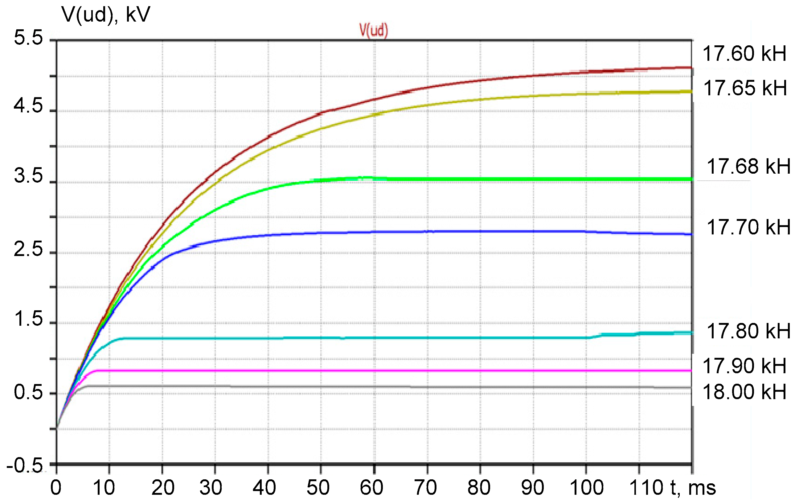
In the simulation, the resonant circuit parameters were selected to match the actual values of the impulse capacitive circuit (ICC) components under investigation: inductance Lr = 23.2 mH, capacitance Cr = 3.47 =3.47 nF, and series resistance RL = 12.7 Ohm. The electrical system (ES) was supplied with a constant voltage of 20 V. During the simulation, the excitation frequency of the output voltage varied within the range of 17.6 to 18.0 kHz to identify the resonant operating point. This frequency range allowed the researchers to evaluate the system's sensitivity to resonance conditions and to assess the voltage amplification behavior near the natural resonant frequency of the LC circuit.
Figure 5 presents the results of the simulation, illustrating the time-dependent behavior of the output voltage of the electrical system (ES), specifically the voltage V(ud) across the storage capacitor CSC. These results demonstrate how the output voltage varies depending on the switching frequency of the inverter transistors T1 and T2, which determines the operating frequency of the resonant circuit. The simulation clearly shows that when the switching frequency approaches the natural resonant frequency of the LC circuit, the output voltage reaches its maximum value due to resonance effects.
Analysis of the curves in Fig. 5 shows that the ES output voltage (V(ud) voltage on capacitor CS) can be adjusted in a wide range by changing its frequency in a narrow range. Thus, the magnitude of the output voltage (V(ud)) is regulated in a wide range (from 5.3 kV to 600 V, i.e., it changes by 883%) with a relatively small (about 2–3%) change in the frequency of the voltage (from 17.6 kHz to 18 kHz). That is, the voltage can be changed by almost an order of magnitude in the considered range of frequency.
In this way, it is possible to create different output voltages of the ES for diagnosing high-voltage insulation of cables of different voltage classes. Since the system has voltage feedback, it is possible to use a digital proportional integral differential (PID) frequency-controlled output voltage controller.
4. Discussion of the Results Obtained
The conducted research confirms the effectiveness of using transformerless high-voltage electrical systems (ESs) based on high-Q resonant inductive-capacitive circuits (ICCs) for non-destructive diagnostics of insulation in high-voltage power equipment. One of the most significant outcomes is the ability to achieve a substantial voltage increase, up to 40–75 kV, by merely adjusting the frequency of the resonant current within a narrow range (from 17.6 to 18 kHz). This fine-tuned frequency regulation leads to resonance, which results in maximum voltage amplification at the output without requiring bulky or expensive step-up transformers [1,2,5,47,49]. Such a principle fundamentally shifts the approach to mobile diagnostics, enabling the development of lightweight, autonomous systems with high diagnostic accuracy.
The use of tightly twisted multi-core of the "litzendraht" type wire coils and high-Q ceramic capacitors has demonstrated a substantial improvement in the efficiency and selectivity of ICCs [4,8,49,52]. Specifically, it was shown that the quality factor (Q-factor) of more than 250 allows for proportional increases in voltage underload and automatic suppression of output during fault conditions (e.g., near-short circuits). These properties enhance not only the performance but also the safety of the ES in field conditions, making it suitable for war-damaged infrastructure in Ukraine where rapid, on-site monitoring is critical [2,40,41,50]. The capability of the ES to maintain stable operation close to idle mode, even under variable capacitive loading, further validates the robustness of the system design.
Moreover, the simulation results confirm the theoretical assumptions regarding the resonant behavior of the system. The findings demonstrate a wide-range voltage control (over 800% variation) enabled by minimal frequency adjustments (just 2–3%). This level of controllability opens the door to a universal diagnostic tool adaptable to various voltage classes of power cables and electric machines. The implementation of a PID-controlled feedback loop ensures that the output voltage remains stable despite load fluctuations, reinforcing the ES’s potential for widespread use in precision insulation diagnostics across diverse power systems.
5. Conclusions
The conducted research substantiates the feasibility and technical viability of constructing compact, transformerless high-voltage resonant-type electrical systems capable of operating at high frequencies and achieving significant voltage amplification without the use of traditional step-up transformers. By integrating a finely tuned inductive-capacitive circuit with a high Q-factor and regulating the resonant current frequency, these systems demonstrate remarkable performance in generating voltages up to 75 kV, while maintaining mobility, efficiency, and rapid response characteristics crucial for diagnosing high-voltage insulation in critical infrastructure. The findings represent a significant advancement in the development of lightweight, portable diagnostic tools for the reliable monitoring of power systems. The main results are as follows:
1. The principles of construction of mobile (small-sized) high-voltage transformerless electrical systems of resonant type have been developed based on the implementation in them of a series inductive-capacitive circuit with a high Q-factor (more than 200) and a high-frequency (40-50 kHz) resonant sinusoidal current. The maximum adjustable Q-factor of the inductive-capacitive circuit and the corresponding maximum increase in the alternating voltage on the load of such an electrical system are ensured by purposeful regulation of the current resonant frequency. According to these principles, it becomes possible to create mobile electrical systems of the resonant type, which can generate voltage up to 75 kV for monitoring the technical condition of high-voltage insulation of power cables, powerful electrical machines and other power facilities of the critical infrastructure of Ukraine.
2. A significant increase in the frequency of the current in the inductive-capacitive circuit of resonant-type electrical systems ensures a corresponding reduction in the pulsed electrical energy transmitted to the load of these systems, as well as an increase in the speed of control and stabilization of modes in the load even when its resistance decreases to zero, which is typical for the breakdown of high-voltage electrical insulation.
3. Generation of resonant currents with a frequency of up to 50 kHz in an inductive-capacitive circuit (having a coil made of multi-core insulated and twisted copper wires of the "litzendraht" type with an inductance of ~25 mH and a O-factor of ~270, as well as a ceramic capacitor with a capacity of ~3.5 nF and a Q-factor of more than 1000) of an experimental sample of such an electrical system ensures a Q-factor of the inductive-capacitive circuit QICC of ~260 and a corresponding ratio of the output voltage of the electrical system to the input voltage without the use of step-up transformers. When connecting the electrical system to a 220 V AC voltage source, a voltage of up to 75 kV appears at the output of a mobile system weighing only up to 5 kg. If necessary, such a system can be autonomous with power supply from batteries.
Author Contributions
A.S. conceptualized the study and led the project administration. D.V. was responsible for methodology development and formal analysis. N.S. carried out data curation and visualization. S.R. contributed to the investigation and fieldwork. A.D. supported the writing of the original draft and data interpretation. R.D. supervised the project and contributed to reviewing and editing the manuscript. All authors have read and agreed to the published version of the manuscript.
Funding
This research received no external funding
Data Availability Statement
The data that support the findings of this study are available from the corresponding author upon reasonable request.
Acknowledgments
This work was conducted within the projects “Development of the theory and methods of the effect of non-sinusoidal voltages and currents and electrothermodynamic processes on the reliability and resource of modern power cable lines” (State registration No. 0123U100693) and "Development of a mobile voltage generation system with variable parameters for monitoring the safety and reliability of high-voltage electrical equipment of power facilities of critical infrastructure of Ukraine" (State registration No. 0123U103724)
Conflicts of Interest
The authors declare no conflicts of interest.
References
- Design of cable lines with a voltage of up to 330, kV. Standard (with changes). SOU-N MEV 40. 1-37471933-49:2011. SE NEC Ukrenergo: Kyiv, 2017; 139р.
- Zolotarev, V.M.; Shcherba, М.А.; Gurin, А.G.; Suprunovska, N.I.; Chopov, Ye.Yu.; Obozny, А.L. Electrotechnological complex for the production of cable systems for voltages up to 400 kV. Proformat: Kyiv, Ukraine, 2017; 594p.
- Milyah, А.N.; Volkov, I.V. Unchangeable current systems based on inductive-capacitive converters. Naukova dumka: Kyiv, Ukraine, 1974; 216p.
- Volkov, I.V.; Gubarevich, V.N.; Isakov, V.N.; Kaban, V.P. Principles of construction and optimization of inductive-capacitive converter circuits. Naukova dumka: Kyiv, Ukraine, 1981; 176.
- Bluhm, H. High Power Particle Beams and Pulsed Power for Industrial Applications. AIP Conference Proceedings 2002, 650, 9–16. [Google Scholar] [CrossRef]
- Vedral, J. Diagnostics of Power Transformers. Non-Destructive Diagnostic of High Voltage Electrical Systems 2023, 193–235. [Google Scholar] [CrossRef]
- Seheda, M.S.; Beshta, O.S.; Gogolyuk, P.F.; Blyznak, Yu.V.; Dychkovskyi, R.D.; Smoliński, A. Mathematical model for the management of the wave processes in three-winding transformers with consideration of the main magnetic flux in mining industry. Journal of Sustainable Mining 2024, 23, 20–39. [Google Scholar] [CrossRef]
- Pazynich, Y.; Kolb, A.; Korcyl, A.; Buketov, V.; Petinova, O. Mathematical model and characteristics of dynamic modes for managing the asynchronous motors at voltage asymmetry. Polityka Energetyczna – Energy Policy Journal 2024, 27, 39–58. [Google Scholar] [CrossRef]
- Beshta, O.S.; Fedoreiko, V.S.; Balakhontsev, O.V.; Khudolii S.S. Dependence of electric drive's thermal state on its operation mode. Naukovyi Visnyk Natsionalnoho Hirnychoho Universytetu 2013, (6), 67-72. Available online: https://nvngu.in.ua/index.php/en/component/jdownloads/finish/44-06/714-2013-6-beshta/0.
- Armstrong, K. How to manage risks with regard to electromagnetic disturbances. 2016 IEEE International Symposium on Electromagnetic Compatibility (EMC) 2016, 72–77. [Google Scholar] [CrossRef]
- Nikolsky, V.; Dychkovskyi, R.; Cabana, E.C.; Howaniec, N.; Jura, B.; Widera, K.; Smoliński, A. The Hydrodynamics of Translational−Rotational Motion of Incompressible Gas Flow within the Working Space of a Vortex Heat Generator. Energies 2022, 15, 1431. [Google Scholar] [CrossRef]
- Beshta, O. S.; Beshta, O. O.; Khudolii, S. S.; Khalaimov, T. O.; Fedoreiko, V. S. Electric vehicle energy consumption taking into account the route topology. Naukovyi Visnyk Natsionalnoho Hirnychoho Universytetu 2024, 2, 104–112. [Google Scholar] [CrossRef]
- Nikolsky, V.; Dychkovskyi, R.; Lobodenko, A.; Ivanova, H.; Cabana, E.C.; Shavarskyi, Ja. Thermodynamics of the developing contact heating of a process liquid. Naukovyi Visnyk Natsionalnoho Hirnychoho Universytetu 2022, (2), 48–53. [Google Scholar]
- Kolb, A.; Pazynich, Y.; Mirek, A.; Petinova, O. Influence of voltage reserve on the parameters of parallel power active compensators in mining. E3S Web Conf. 2020, 201, 01024. [Google Scholar] [CrossRef]
- Shadlu, M.S. Harmonic and imbalance compensation in electric railway systems using modular multilevel converters under varying load conditions. 2018 9th Annual Power Electronics, Drives Systems and Technologies Conference (PEDSTC) 2018, 363–368. [CrossRef]
- Sala, D.; Richert, M. Perspectives of Additive Manufacturing in 5.0 Industry. Materials 2025, 18(2), 429. [CrossRef]
- Fedoreiko, V.; Zahorodnii, R.; Lutsyk, I.; Rutylo, M.; Bureha, N. Modelling of resource-saving control modes of a bioheat generator using neuro-fuzzy controllers. IOP Conference Series: Earth and Environmental Science 2025, 1457(1), 012005. [Google Scholar] [CrossRef]
- Dychkovskyi, R.; Dyczko, A.; Borojević Šoštarić, S. Foreword: Physical and Chemical Geotechnologies – Innovations in Mining and Energy. E3S Web of Conferences 2024, 567, 00001. [Google Scholar] [CrossRef]
- Myronova, I.; Kovrov, O.; Dudek, M.; Voronkova, Y.; Kononenko, M. Environmental assessment of the impact of iron ore mine emissions on biological indicators of winter wheat. IOP Conference Series: Earth and Environmental Science 2025, 1457(1), 012004. [Google Scholar] [CrossRef]
- Hutniczak, A.K.; Bryś, W.; Dychkovskyi, R.; Gaj, R.; Dyczko, A.; Błońska, A.; Bierza, K.; Bacler-Żbikowska, B.; Woźniak, G. Identifying and understanding novel ecosystem functions: a scientific approach to nature restoration law. Journal of Water and Land Development 2025, 203–203. [Google Scholar] [CrossRef]
- Lewicka, B.; Lewicka, D. Environmental risk management in the context of environmental management systems for agriculture based on the ISO 14001:2015 standard. Acta Innovations 2019, 33, 63–72. [Google Scholar] [CrossRef]
- Richert, M.; Dudek, M.; Sala, D. Surface Quality as a Factor Affecting the Functionality of Products Manufactured with Metal and 3D Printing Technologies. Materials 2024, 17(21), 5371. [Google Scholar] [CrossRef] [PubMed]
- Polyanska, A.; Pazynich, Y.; Mykhailyshyn, K.; Babets, D.; Toś, P. Aspects of energy efficiency management for rational energy resource utilization. Rudarsko-Geološko-Naftni Zbornik 2024, 39(3), 13–26. [CrossRef]
- Lewicka, D. (2010). The impact of HRM on creating proinnovative work environment. International Journal of Innovation and Learning, 7(4), 430. [CrossRef]
- Kurande, V. (2013). Reliability of Diagnostic Methods in Indian Traditional Ayurvedic Medicine. Reliability of Diagnostic Methods in Indian Traditional Ayurvedic Medicine, 1–107. [CrossRef]
- Kasten, D. G., Sebo, S. A., & Lauletta, J. L. (2014). High voltage diagnostic measurements for surge arrester condition monitoring. 2014 IEEE International Power Modulator and High Voltage Conference (IPMHVC), 576–579. [CrossRef]
- International Electrotechnical Commission. (2006). IEC 60060-3: High-voltage test techniques – Part 3: Definitions and requirements for on-site testing. Geneva: IEC.
- Hill, D. R. (1975). High Voltage Generation. Principles of Diagnostic X-Ray Apparatus, 147–169. [CrossRef]
- Institute of Electrical and Electronics Engineers. IEEE Standard Techniques for High Voltage Testing (IEEE Std 4-2013). IEEE: New York, NY, 2013; 21p.
- Sokolov, V.; Bakunov, A.; Ivanov, D. Mobile high-voltage resonant test systems for field diagnostics of cable lines. IEEE Transactions on Dielectrics and Electrical Insulation 2019, 26(4), 1095–1102. [Google Scholar]
- Popov, M.; Steennis, E.; Wetzer, J. M. Resonant testing of high-voltage equipment: Advantages and limitations in on-site diagnostics. Electric Power Systems Research 2020, 187, 106466. [Google Scholar]
- Abdel-Salam, M. Applications of High-Voltage Engineering in Industry. High-Voltage Engineering 2018, 645–680. [CrossRef]
- Seeram, E. Digital Radiography: An Overview. Digital Radiography 2019, 1–19. [Google Scholar] [CrossRef]
- Kasten, D. G.; Sebo, S. A.; Lauletta, J. L. High voltage diagnostic measurements for surge arrester condition monitoring. 2014 IEEE International Power Modulator and High Voltage Conference (IPMHVC) 2014, 576–579. [Google Scholar] [CrossRef]
- Zhao, L.; Xu, Z.; He, J. Digital control strategy for resonant test systems applied to HVDC cable insulation testing. IEEE Transactions on Power Delivery 2018, 33(5), 2285–2293. [Google Scholar]
- Hajilou, M.; Khalili, S.; Farzanehfard, H. Single Switch ZVS Transformerless Resonant High Step-up Converter. 2021 12th Power Electronics, Drive Systems, and Technologies Conference (PEDSTC) 2021, 1–6. [CrossRef]
- Mishima, T. Latest Development of SiC Power Module-based Single-Stage AC-AC Resonant Converter for High-Frequency Induction Heating Applications. 2018 International Power Electronics Conference (IPEC-Niigata 2018 -ECCE Asia) 2018, 872–877. [CrossRef]
- Ochin, P.; Gilchuk, A. V.; Monastyrsky, G. E.; Koval, Y.; Shcherba, A.A.; Zaharchenko, S. N. Martensitic Transformation in Spark Plasma Sintered Compacts of Ni-Mn-Ga Powders Prepared by Spark Erosion Method in Cryogenic Liquids. Materials Science Forum 2013, 738–739, 451–455. [CrossRef]
- Nguyen, P.-K.; Jin, S.; Berkowitz, A. E. MnBi particles with high energy density made by spark erosion. Journal of Applied Physics 2014, 115(17). [CrossRef]
- Sizonenko, O.N.; Grigoryev, E.G., Zaichenko, A.D.; Pristash, N.S.; Torpakov, A.S.; Lipyan, Y.V.; Kovalenko, A.A. Plasma methods of obtainment of multifunctional composite materials, dispersion-hardened by nanoparticles. IOP Conference Series: Materials Science and Engineering 2016, 130, 012048. Available online: https://iopscience.iop.org/article/10.1088/1757-899X/130/1/012048.
- Vovchenko, A.I.; Boguslavsky, L.Z.; Miroshnichenko, L.N. Trends in the development of high-power high-voltage pulse current generators at the Institute of IPPT of NAS of Ukraine. Tekhnichna Elektrodynamika 2010, (5), 69–74. [Google Scholar]
- Pentegov, I.V. Fundamentals of the theory of charging circuits of capacitive energy storage devices. Naukova Dumka: Kyiv, Ukraine, 1982; 422p.
- Ivashchenko, D.S.; Shcherba, A.A.; Suprunovska, N.I. Analyzing probabilistic properties of electrical characteristics in the circuits containing stochastic load. 2-nd International Conference on Intelligent Energy and Power Systems (IEPS) 2016, 1-4. [CrossRef]
- Suprunovska, N.I.; Shcherba, А.А. Processes of energy redistribution between parallel connected capacitors. Tekhnichna Elektrodynamika 2015, (4), 3–11. [Google Scholar]
- Vinnychenko, D.V. The influence of electrical parameters of high-voltage electric discharge units for the synthesis of nanocarbon on their productivity and specific energy consumption. Tekhnichna Elektrodynamika 2016, (4), 95–97. [Google Scholar] [CrossRef]
- Vinnychenko, D.V.; Nazarova, N.S.; Vinnychenko, I.L. Research of characteristics of high voltage transformerless resonant charger of capacitary storage device. Tekhnichna Elektrodynamika 2023, (2), 17–21. [Google Scholar] [CrossRef]
- Zhang, X.; Pang, B. , Liu, X.; Liu, S.; Xu, P.; Li, Ya, Liu, Yi.; Qi, L.; Xie, Q. Review on detection and analysis of partial discharge along power cables. Energies 2021, 14, 7692. [Google Scholar] [CrossRef]
- Eigner, A.; Rethmeier, K. An overview on the current status of partial discharge measurements on AC high voltage cable accessories. IEEE Electrical Insulation Magazine 2016, 32(2), 48–55. [Google Scholar] [CrossRef]
- Danikas, M. G.; Pearmain, A. J. Discharge energy/material damage and thermal considerations in a solid/liquid insulating system. Proceedings of the 19th Electrical Electronics Insulation Conference, 2002, 320–323. [CrossRef]
- Titko, A.I.; Vaskovsky, Yu.N. Scientific foundations, methods and diagnostic tools for asynchronous motors. Institute of Electrodynamics of the National Academy of Sciences of Ukraine: Kyiv, 2015; 300.
- Kumar, H.; Shafiq, M.; Kauhaniemi, K.; Elmusrati, M.A. Review on the classification of partial discharges in medium-voltage cables: detection, feature extraction, artificial intelligence-based classification, and optimization techniques. Energies 2024, 17, 1142. [Google Scholar] [CrossRef]
- Du, W.-S. Simultaneous generalizations of fixed point theorems of Mizoguchi-Takahashi type, Nadler type Banach type, Kannan type and Chatterjee type. Nonlinear Analysis and Differential Equations 2017, 5, 171–180. [Google Scholar] [CrossRef]
Figure 1.
The structural diagram of the power part of the experimental sample of high-voltage transformerless electric system using serial high-quality inductive-capacitive circuits and high-frequency sinusoidal currents.
Figure 1.
The structural diagram of the power part of the experimental sample of high-voltage transformerless electric system using serial high-quality inductive-capacitive circuits and high-frequency sinusoidal currents.
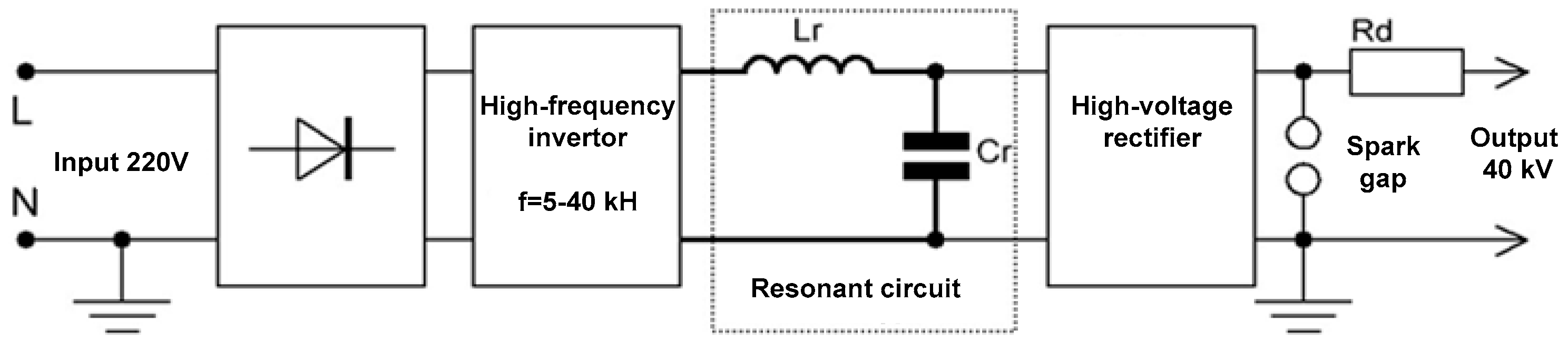
Figure 2.
Detailed structural diagram of the power part of the experimental sample of high-voltage transformerless electric system.
Figure 2.
Detailed structural diagram of the power part of the experimental sample of high-voltage transformerless electric system.
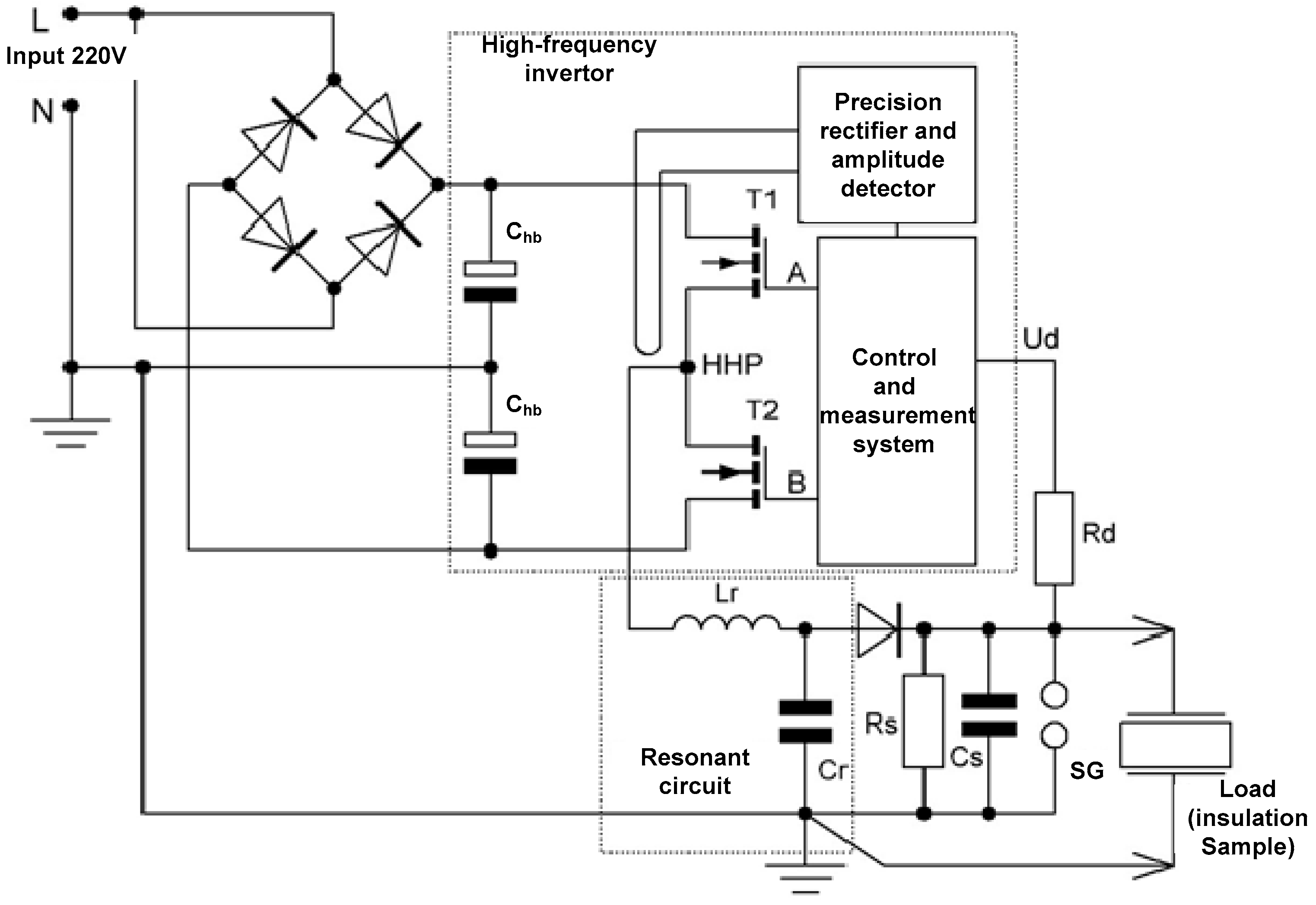
Figure 3.
Control system for the modes of the inverter transistors of the experimental sample of high-voltage transformerless electric system.
Figure 3.
Control system for the modes of the inverter transistors of the experimental sample of high-voltage transformerless electric system.
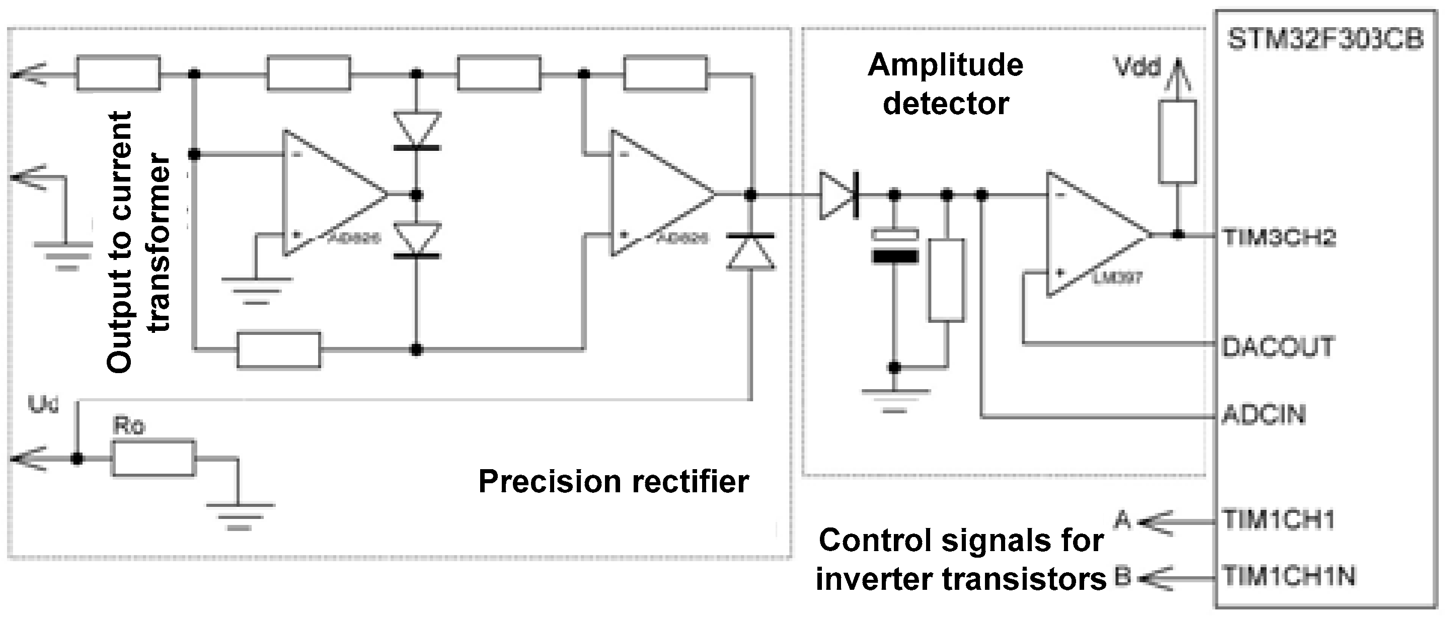
Figure 4.
Scheme for simulation of a transformerless ES of resonant type with the structural diagram presented in Fig. 2 using LTSpice software.
Figure 4.
Scheme for simulation of a transformerless ES of resonant type with the structural diagram presented in Fig. 2 using LTSpice software.
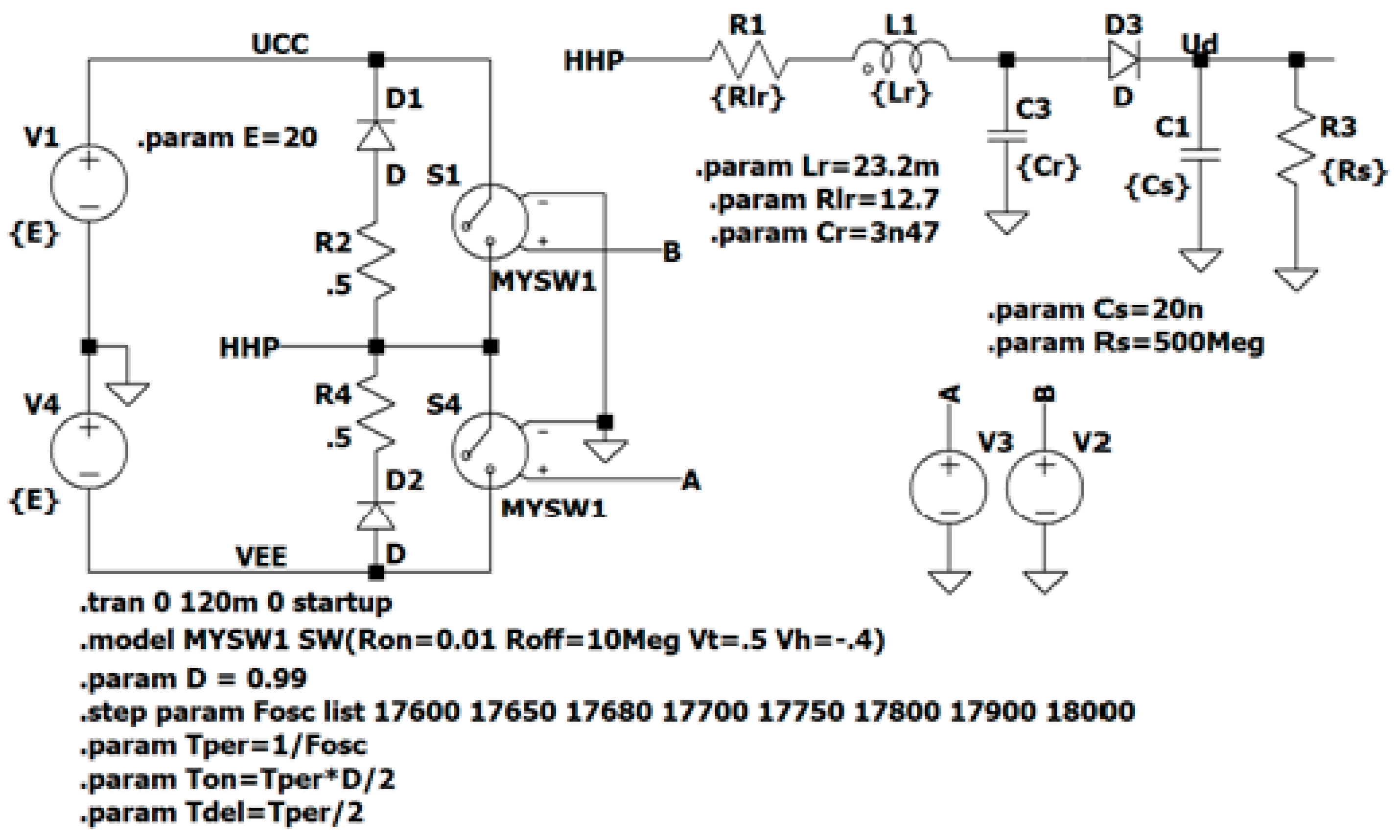
Figure 5.
Change in time of the output voltage of ES (voltage V(ud) on the capacitor CS), depending on the frequency of the output voltage (switching frequency of the inverter transistors T1 and T2).
Figure 5.
Change in time of the output voltage of ES (voltage V(ud) on the capacitor CS), depending on the frequency of the output voltage (switching frequency of the inverter transistors T1 and T2).
Disclaimer/Publisher’s Note: The statements, opinions and data contained in all publications are solely those of the individual author(s) and contributor(s) and not of MDPI and/or the editor(s). MDPI and/or the editor(s) disclaim responsibility for any injury to people or property resulting from any ideas, methods, instructions or products referred to in the content. |
© 2025 by the authors. Licensee MDPI, Basel, Switzerland. This article is an open access article distributed under the terms and conditions of the Creative Commons Attribution (CC BY) license (http://creativecommons.org/licenses/by/4.0/).
Copyright: This open access article is published under a Creative Commons CC BY 4.0 license, which permit the free download, distribution, and reuse, provided that the author and preprint are cited in any reuse.


