
Submitted:
09 June 2025
Posted:
10 June 2025
You are already at the latest version
Abstract
The construction industry is exploring alternatives to traditional steel reinforcement in concrete due to steel's corrosion vulnerability. Glass Fiber Reinforced Polymer (GFRP) and Basalt Fiber Reinforced Polymer (BFRP), known for their high tensile strength and corrosion resistance, are viable options. This study evaluates the flexural performance of concrete beams reinforced with GFRP, BFRP, and hybrid systems combining these materials with steel, following ACI 440.1R-15 guidelines. Twelve beams were assessed under three-point bending to compare their flexural strength, ductility, and failure modes against steel reinforcement. Results indicate that GFRP and BFRP beams achieve higher ultimate load capacities but lower deflections at failure than steel. Hybrid reinforcements enhance both load capacity and deflection performance. However, GFRP and BFRP beams show reduced energy absorption, suggesting that hybrid systems could better support critical applications like seismic and impact-prone structures by improving ductility and load handling.
Keywords:
Basalt Fiber Reinforced Polymers (GFRP)
; hybrid-reinforced beams
; ductility
; flexure tests
; Glass Fiber Reinforced Polymers (GFRP)
1. Introduction
Fiber Reinforced Polymer (FRP) composites were initially developed for aerospace and military applications [1,2]; they soon found their way into civil engineering applications due to their superior corrosion resistance and high strength-to-weight ratio. In particular, Glass Fiber Reinforced Polymer (GFRP) and recently Basalt Fiber Reinforced Polymer (BFRP), have gained significant traction as concrete elements reinforcement [3,4,5,6,7,8,9,10,11]. They emerged as a solution to the limitations of steel reinforcement corrosion, particularly in environments where steel is prone to corrosion. Their corrosion resistance, high tensile-strength-to-weight ratio, and durability in aggressive environments have made them an attractive choice in multiple structural applications. BFRP, a relatively newer material, offers similar advantages to GFRP, but with enhanced thermal stability and sustainability and is increasingly being considered for fire-prone areas and sustainable building projects [12,13,14]. Unlike GFRP, BFRP fibers are derived from natural basalt rock, making them more environmentally friendly as their natural basalt composition reduces their carbon footprint. In general, the introduction of FRP materials into structural engineering applications, particularly in reinforcing concrete elements, allows for the development of structures with extended service life, reduced maintenance, and improved performance in aggressive environments [15,16,17,18,19].
GFRP bars typically exhibit tensile strength in the range of 500 to 1500 MPa, depending on the fiber content and the manufacturing process. However, GFRP's elastic modulus is significantly lower than that of steel, leading to some concerns related to ductility. On the other hand, BFRP offers a higher elastic modulus and performs better in high-temperature environments, as it maintains its mechanical properties up to approximately 350°C [12,17].
The design and application of FRP reinforcement are governed by several ACI guidelines [20-22]. These guidelines emphasize the importance of considering both strength and serviceability limits, particularly for flexural members where deflections and cracking need to be controlled. For example, GFRP-reinforced beams require careful attention to crack width limits, and design recommendations include the use of crack control reinforcement or increasing the section depth. This may constitute a drawback for using GFRP in reinforcing concrete elements. BFRP, while not yet fully integrated into design guidelines, is being studied for future inclusion in codes of practice and standards.
The durability of FRP-reinforced concrete structures is influenced by the bond between the FRP bars and the concrete [23,24]. Studies have shown that the bond strength between FRP bars and concrete is generally weaker than that of steel, which can lead to premature debonding failure if not properly accounted for during the design process [15,25]. To address this issue, ACI guidelines provide specific recommendations for the development length of FRP bars, which are typically longer than those required for steel reinforcement [20,21,22]. In addition to the bond strength concern, other factors such as serviceability requirements must be considered when assessing the performance of FRP-reinforced concrete beams. Few investigations have been performed on estimating the deflection of beams reinforced with GFRP and BFRP bars [26,27,28].
Despite the advantages of GFRP and BFRP in reinforced concrete beams, in addition to the above-mentioned constraints, other limitations still exist. One of the primary challenges is the higher upfront cost of FRP materials compared to traditional steel reinforcement. Although FRP offers long-term cost savings due to reduced maintenance and longer service life, the initial cost of materials can be prohibitive for some projects [29]. Lack of standardized design codes or guidelines for BFRP, as mentioned above, presents another challenge.
The future of GFRP and BFRP as structural concrete elements reinforcement looks promising as advancements in material science and sustainability continue to drive the development of new FRP technologies. Sustainability, a crucial factor nowadays, will shape the future of using FRP materials in structural engineering applications. BFRP, with its natural basalt composition, is well-positioned to meet the current growing demand for environmentally friendly structures. Advances in fiber production and composite manufacturing are expected to lower the upfront cost of FRP materials, making them more accessible for large-scale infrastructure projects [19].
Research into hybrid reinforcement that combines FRP with steel offers significant potential for improving the overall performance of reinforced concrete structures [30,31,32,33,34]. These hybrid systems can provide the best of both worlds, combining the corrosion resistance of FRP with the high elastic modulus and ductility of steel, thereby overcoming some of the FRP limitations.
2. Research Significance
This research underscores the transformative potential of Fiber Reinforced Polymers (FRPs) like GFRP and BFRP in modern construction, challenging traditional steel reinforcement in concrete beams. By incorporating advanced composites, this study not only aims to elevate structural durability and reduce environmental impact but also seeks to enhance the understanding of the flexural performance of FRP-reinforced beams. The findings could lead to broader adoption of FRP materials, influencing future design practices and FRP design guidelines, thereby contributing significantly to sustainability and innovation in structural engineering.
3. Research Objectives
As construction practices evolve and sustainability becomes a core focus, the use of FRPs in concrete beams has gained considerable attention. As mentioned earlier, these materials are considered alternatives to traditional steel reinforcement, offering advantages such as superior corrosion resistance, lightweight properties, and high tensile strength. However, despite these benefits, when used to reinforce beams, there is a critical need to conduct flexure testing (among other tests) to fully understand and compare the performance of GFRP, BFRP, and hybrid reinforcement systems under real conditions.
While GFRP and BFRP offer promising advantages over steel, there remain several unanswered questions regarding their flexural behavior in reinforced concrete beams. Key aspects such as flexural strength, deflection characteristics, ductility, cracking patterns, and failure modes need to be rigorously assessed and compared to those of traditional steel-reinforced beams. Furthermore, hybrid reinforcement systems, which combine steel and FRP, also require evaluation to determine whether they can provide enhanced performance in terms of load-bearing capacity and ductility.
The primary objective of this research is to experimentally investigate the flexural behavior of concrete beams reinforced with GFRP, BFRP, and hybrid combinations of these materials with steel. Specifically, the study aims to
- compare the flexural strength of GFRP, BFRP, and hybrid-reinforced beams to that of steel-reinforced beams,
- analyze the deflection characteristics of each type of beam, focusing on the ductility behavior,
- assess the cracking patterns and the overall failure modes to determine the suitability of GFRP, BFRP, and hybrid reinforcements for different structural applications, and
- examine whether hybrid reinforcement systems, such as Steel/GFRP, Steel/BFRP, and GFRP/BFRP combinations, offer better alternatives to traditional steel reinforcement, particularly in terms of ductility.
4. The Experimental Investigation: Materials and Methodology
While several studies have highlighted the advantages of FRPs, the actual performance of GFRP, BFRP, and hybrid reinforcements in terms of load capacity, cracking behavior, and failure mechanisms still need further examination. In addition, ACI [20,21,22] provides guidelines for designing structural concrete reinforced with FRP bars, but further experimental validation is required to assess how these materials (particularly GFRP, BFRP, and hybrid reinforcement) behave in beams subject to flexure loading conditions.
- beams reinforced with steel (control group),
- beams reinforced with GFRP,
- beams reinforced with BFRP,
- beams reinforced with a hybrid of Steel and GFRP,
- beams reinforced with a hybrid of Steel and BFRP, and
- beams reinforced with a hybrid of GFRP and BFRP.
Each set consists of two replica beams to increase the reliability of the test results. The flexure testing is intended to evaluate:
- the flexural strength based on the nominal moment and load capacity,
- the deflection profiles to assess ductility,
- crack propagation and failure modes of each reinforcement type, and
- ductility of beams compared to that of steel-reinforced beams.
This experimental study provides a comprehensive comparison of the flexural behavior of beams reinforced with GFRP, BFRP, and hybrid reinforcement systems. It will identify the advantages of hybrid systems in enhancing ductility and load-bearing capacity. Furthermore, it will offer recommendations for incorporating GFRP and BFRP reinforcements into structural design codes, contributing to the development of sustainable and high-performance concrete structures.
The length of all the tested beams is 2.0 m and they are tested over a span of 1.85 m. All the beams are reinforced in shear with no 8 @ 100 mm and have top reinforcement of 2 no. 10. The cross-section dimensions of the beams are 200mm×400mm.
The concrete used in casting the beams has a mix designed to produce a 28d cylinder strength fc/ of 25 MPa. The mix is composed of
- 350 kg/m3 Ordinary Portland Cement
- w/c ratio of about 0.4
- 615 kg/m3 fine aggregates (sand)
- 1100 kg/m3 coarse aggregate (1'', 2"' equal portions)
- Super plasticizer Skiament C494 Type F.
A 1.0 m3 capacity mixer is used to mix the concrete and 100 mm × 300 mm concrete cylinders were extracted from the same mix to test the 7d and 28d concrete compressive strength. Figure 2 shows the casting and curing of the casted beams.
A concrete slump test is performed on the concrete mix which yielded a 20 mm slump indicating low concrete workability. The mix temperature measures 32.5oC which is about the recommended mix temperature (10 – 32 oC). The air content of the fresh concrete measures 3.2%. These tests are shown in Figure 3.
Three cylinders (150mm×300mm) are tested after 7 days in compression yielding a 7d concrete compressive strength of about 18 MPa. After 14 days, rebound tests using a Schmidt hammer are performed on the beams. Readings were taken on each beam yielding an average cube (200mm×200mm) strength of 24.5 MPa. Applying correction factors of 1.05 for the cube size and 1.25 for the cylinder strength yields fc/(14d) = 20.6 MPa. Three cylinders (150mm×300mm) are tested after 28 days in compression yielding a 28d average concrete compressive strength of 24.8 MPa.
Six samples of the 12 mm and the 8 mm steel bars adopted for flexure and shear reinforcement are tested in uniaxial tension. The sample length is 400 mm with a gauge length of 260 mm. The results revealed a yield strength of 465±35 MPa and 358±2.9 MPa for the 12 mm bars and the 8 mm bars, respectively. Figure 4 shows the stress-strain relations resulting from the tests performed on these bars. The resulting values for the steel yield strength (465 MPa and 360 MPa) are adopted in the analytical calculations of the beams’ nominal moment and shear.
The GFRP and BFRP bars were tested earlier [35] yielding tensile strength of 1060 MPa and 1470 MPa, rupture strain of 0.022 and 0.026, and modulus of elasticity of 47.5 GPa and 59.7 GPa, respectively. Three samples of the GFRP bars (8 mm in diameter) are tested in uniaxial tension. Both ends of each bar are encased in metal sleeves and epoxy to minimize the gripping effect on the fibers. Despite these precautions, failure occurs at the gipping zones in all samples. As such, test results are used combined with results available from literature and listed in ACI 440.6-08. The stress-strain curves for the three tested samples are shown in Figure 5. The sample length is 400 mm with a gauge length of 260 mm. The results reveal a GFRP elastic modulus of 38.2±1.4 GPa, an ultimate strength of 567±292 MPa, and an ultimate strain of 0.0183±0.008. These values are close to the values available in the literature as listed above.
Three samples of the BFRP bars (10 mm in diameter) are tested in uniaxial tension. The sample length is 400 mm with a gauge length of 260 mm. Both ends of each BFRP bar are encased in metal sleeves and epoxy to minimize the gripping effect. Once again, failure occurs at the gripping zones; thus, test results are used in combination with previous tests listed above. The stress-strain curves for the three tested samples are shown in Fig. 6. The results reveal a BFRP elastic modulus of 43.2±0.6 GPa, an ultimate strength of 790±41 MPa, and an ultimate strain of 0.033±0.002.
All beams are tested in flexure in a 3-point loading scheme monotonically to failure (Figure 6). Load is applied using an actuator that is connected to a load cell measuring the applied load.
Mid-span deflection is measured using an LVDT (Linear Variable Differential Transformer) attached to the soffit of the beam at mid-span. Three strain gauges are attached to the reinforcement (Figure 6) to measure the tensile strains in the reinforcement bars while an additional strain gauge is attached to the concrete in compression. All readings (load, deflection, and strains) are collected via a data acquisition system.
5. The Analytical Investigation
An analytical investigation is conducted based on ACI code of practice and guidelines [20,36] to compare the experimental results with the analytical predictions. Based on the equilibrium of forces and compatibility of strain conditions (Figure 7), the nominal moments for beams reinforced with steel, GFRP, BFRP, and hybrid reinforcement are calculated. ACI 318-19 [36] is used for beams reinforced with steel while ACI 440.6R-08 [20] is adopted for beams reinforced with FRP and hybrid systems.
Furthermore, calculations for nominal shear are also performed based on the above-mentioned code of practice and guidelines for these beams. In these calculations, the concrete, steel, and FRP mechanical properties listed in Table 2 are adopted.
5.1. Nominal Moment
With reference to Figure 7, the equilibrium of forces condition yields
where fc/ is the 28d concrete compressive strength, Fs and Ff are the stresses in the steel and FRP bars, respectively, Fy-s is the yield stresses of the steel bars, Fu-f is the rupture stress of the FRP bars, As and Af are the areas of the steel and FRP bars, respectively, a is the depth of the equivalent concrete compression block and b is the width of the beam’s cross-section.
Using the compatibility of strain condition to check steel yielding and FRP rupture,
where, εc, εs, and εf are the strains in the concrete top fibers, steel bars and FRP bars, respectively, and Es and Ef are the elastic moduli of the steel and FRP, respectively, εy-s is the yield strain of the steel, εu-f is the rupture strain of the FRP, εcu is the concrete crushing strain, d is the depth to the reinforcement, and c is the depth to the neutral axis of the cross-section.
Solving Equations 1 and 2 simultaneously defines the failure mode and yields the nominal moment Mn, which is given by
where Pu-M is the failure load corresponding to the three-point loading scheme (Figure 7), and L is the tested span of the beam (1.85 m).
5.2. Nominal Shear
The shear strength of the beam Vn is calculated as follows:
where Vc is concrete shear resistance, Av is the area of the stirrups, Fy-v is the yield stress of the stirrups steel, s is the spacing between the stirrups, and Pu-V is the failure load corresponding to the nominal shear. For FRP- and hybrid-reinforced beams, the concrete shear strength is significantly reduced via a factor κ (ACI 440.1R-15) since the contribution of the FRP to the dowel action has not been determined. This factor is calculated based on the modular ratio between the FRP and the concrete nf and the FRP reinforcement ratio ρf as follows:
5.3. Cracking Moment
The beam’s cracking moment is calculated based on ACI 318-19 using the modulus of rupture fr as follows:
where S is the elastic section modulus of the beam’s cross-section, Mcr is the cracking moment and Pcr is the cracking load corresponding to the three-point loading scheme.
5.4. Results of the Analytical Investigation
Based on Equations 1 to 5, the analytically calculated nominal moment, nominal shear, and the expected failure modes for all beams are summarized in Table 3. Furthermore, using Equation 6 yields a cracking moment and cracking load of 16.5 kN·m and 35.7 kN, respectively.
6. Experimental Investigation Results and Discussion
The results of the experimental investigation are summarized in Table 4. The table lists the encountered failure loads, the deflection corresponding to the failure load, and the observed modes of failure for all beams.
6.1. Cracking Moment and Load-Deflection Relations
Cracking patterns and cracks’ propagation were recorded and marked during testing of the beams; these are shown in Figure 8. The load-deflection curves (Figure 9) and the cracking patterns show that all beams exhibit cracking around the values calculated by Equation 6. Cracks appeared and propagated in the vicinity of the beams’ midspan indicating flexure failure for all beams. As such, as indicated earlier via the previous calculations for shear capacity, the experimental observations indicate that all beams failed in flexure.
Table 4 and Fig. 8 also show the failure modes encountered experimentally. All failure modes agreed with those predicted analytically except for beams reinforced with BFRP bars where debonding of these bars was encountered before concrete crushing.
6.2. Ductility
To compare the ductility of the tested beams, a ductility index is calculated based on the concept shown in Figure 9. The areas under the load-deflection curves are calculated for all the tested beams to indicate the energy absorption capacity (toughness) of the beam. This area indicates the ability of the beam to sustain dynamic or cyclic loads. The said areas are calculated and listed in Table 5 for all beams. They are also correlated to the control beam traditionally reinforced with steel bars in this table. Furthermore, the table compares the ductility index of all the tested beams to the control beams traditionally reinforced with steel bars.
6.3. Failure Modes
Failure modes observed during the experimental investigation are listed in Table 4 and shown in Figure 8. All failure modes agree with those analytically predicted except for beams reinforced with BFRP where debonding of the BFRP from concrete was encountered before concrete crushing as shown in Figure 4. The compressive concrete stains recorded during testing of all the beams are plotted in Figure 10.
Knowing that the crushing of concrete takes place at around 0.003 strain, the shown results also agree with the failure modes outlined above for the beams.
The tensile stains in the steel, GFRP, and BFRP reinforcement bars recorded during testing of all the beams are plotted in Figure 11a,b. Steel yielding and GFRP rupture or BFRP debonding are evident from the strain measurement and well-agree with the failure modes observed during the tests and predicted from the analytical investigation.
6.4. Investigation Outcomes
Results of the analytical and experimental investigations reveal the following outcomes:
- Load Capacity: GFRP- and BFRP-reinforced beams generally exhibited higher ultimate load capacity compared to Steel-reinforced beams; 8% and 12%, respectively. Hybrid GFRP-Steel and BFRP-Steel reinforced beams also show a higher load capacity compared to steel-reinforced beams; 8% and 17%, respectively. Hybrid GFRP-BFRP reinforced beams do not improve the load capacity due to rupture of the BFRP bars.
- Deflection: GFRP- and BFRP-reinforced beams show significantly lower deflection at failure compared to Steel-reinforced beams; 62% and 42% of the steel-reinforced beams, respectively. Hybrid GFRP-Steel and BFRP-Steel reinforced beams improve this behavior where they show 90% and 48% of the Steel-reinforced beams' defection.
- Failure Modes: GFRP-reinforced beams failed due to GFRP rupture, while BFRP beams experienced debonding or concrete crushing before rupture. Hybrid GFRP-Steel and BFRP-Steel reinforced beams first exhibit steel yielding followed by GFRP rupture for GFRP-reinforced beams or concrete crushing for BFRP-reinforced beams. All failure modes well agree with those predicted analytically.
- Ductility: GFRP- and BFRP-reinforced beams exhibited lower ductility compared to Steel-reinforced beams, as evidenced by their ductility indices; ductility index of steel-reinforced, GFRP-reinforced and BFRP-reinforced beams are 7.4, 4.4, and 3.1, respectively. The ductility improves significantly for hybrid systems of GFRP-Steel and BFRP-Steel reinforced beams; ductility indices are 8.0 and 4.7, respectively.
- Energy Absorption: The area under the load-deflection curve indicating energy absorption capacity and resistance to failure when subject to repeated or cyclic loading. Steel-reinforced beams show the highest area and a superior behavior to all other reinforced beams. The lowest areas are recorded for the GFRP-reinforced beams and the BFRP-reinforced beams (41% and 23% compared to steel-reinforced beams). The hybrid GFRP-Steel and BFRP-Steel reinforcement systems improve this behavior showing 64% and 41%, respectively of the area under the load-deflection curve recorded for steel-reinforced beams.
7. Conclusions
The paper investigates the flexural performance of concrete beams reinforced with GFRP, BFRP, and hybrid reinforcement systems. The study focuses on understanding how these materials compare to traditional steel reinforcement regarding flexural strength, ductility, cracking behavior, and failure modes. Twelve beams are tested, each group reinforced with one type of material (steel, GFRP, BFRP, or hybrids). A three-point load flexural testing scheme is performed, and deflections, strains, and failure loads are recorded.
- Given the limited size of the specimen analyzed in this research, the following general conclusions are deducted from the investigation:
- Special consideration must be adopted in designing beams reinforced with GFRP or BFRP bars regarding
- Longer development length is required when using BFRP bars in reinforcing beams. This is not essentially required for GFRP-reinforced beams.
Hybrid GFRP-Steel reinforced beams showed significantly better ductility and increased toughness. Hybrid BFRP-Steel reinforced beams do not show the same improvement but still show better behavior in ductility and toughness than BFRP-reinforcement beams.
In general, it can be concluded that GFRP- and BFRP-reinforced beams require careful consideration in design to avoid brittle failure. On the other hand, hybrid GFRP-Steel and BFRP-Steel reinforced beams may offer a better solution that improves both load-carrying capacity and ductility, especially in critical applications like seismic zones or impact-prone structures.
Author Contributions
Conceptualization, E.S.A and M.A.; methodology, E.S.A. and M.A.; validation, Y.E., Y.E. and E.S.A; formal analysis, Y.E, Y.E. and Z.E.; investigation, Y.E, Y.E. and Z.E.; resources, E.S.A.; data curation, Y.E.,Y.E., and O.A.; writing—original draft preparation, Y.E. and Y.E.; writing—review and editing, E.S.A.; visualization, Y.E. and Y.E.; supervision, E.S.A. and M.A.; funding acquisition, E.S.A. All authors have read and agreed to the published version of the manuscript.
Funding
This research received no external funding.
Institutional Review Board Statement
Not applicable.
Data Availability Statement
The raw data supporting the conclusions of this article will be made available by the authors on request.
Conflicts of Interest
The authors declare no conflicts of interest.
References
- Balakrishnan, P.; John, M.J.; Pothen, L.; Sreekala, M.S.; Thomas, S. Natural fibre and polymer matrix composites and their applications in aerospace engineering. In Advanced composite materials for aerospace engineering. In Advanced composite materials for aerospace engineering; Woodhead Publishing, 2016; pp. 365–383. [Google Scholar] [CrossRef]
- Asim, M.; Saba, N.; Jawaid, M.; Nasir, M. Potential of natural fiber/biomass filler-reinforced polymer composites in aerospace applications. In Sustainable composites for aerospace applications. In Sustainable composites for aerospace applications; Woodhead Publishing, 2018; pp. 253–268. [Google Scholar] [CrossRef]
- Nanni, A. Flexural behavior and design of RC members using FRP reinforcement. Journal of Structural Engineering 1993, 119, 44–59. [Google Scholar] [CrossRef]
- Benmokrane, B.; Xu, H.; Nishizaki, I. Aramid and carbon fibre-reinforced plastic prestressed ground anchors and their field applications. Canadian Journal of Civil Engineering 1997, 24, 968–985. [Google Scholar] [CrossRef]
- Daniel, I.M.; Ishai, O. Engineering mechanics of composite materials; Oxford University Press Inc.: Oxford, UK, 1994. [Google Scholar]
- Sayed-Ahmed, E.Y.; Lissel, S.L.; Tadros, G.; Shrive, N.G. Carbon fibre reinforced polymer (CFRP) post-tensioned masonry diaphragm walls: prestressing, behaviour, and design recommendations. Canadian Journal of Civil Engineering 1999, 26, 324–344. [Google Scholar] [CrossRef]
- Gudonis, E.; Timinskas, E.; Gribniak, V.; Kaklauskas, G.; Arnautov, A.K.; Tamulenas, V. FRP reinforcement for concrete structures: state-of-the-art review of application and design. Engineering Structures and Technologies 2013, 5, 147–58. [Google Scholar] [CrossRef]
- Kim, S.; Kim, S. Flexural behavior of concrete beams with steel bar and FRP reinforcement. Journal of Asian Architecture and Building Eng. 2019, 18, 89–97. [Google Scholar] [CrossRef]
- Hollaway, L.C. A review of the present and future utilization of FRP composites in the civil infrastructure with reference to their important in-service properties. Construction and Building Materials 2010, 24, 2419–2445. [Google Scholar] [CrossRef]
- Ovitigala, T. Structural behavior of concrete beams reinforced with basalt fiber reinforced polymer (BFRP) bars. PhD Dissertation, University of Illinois at Chicago, USA, 2012. [Google Scholar]
- Zaman, A.; Gutub, S.A.; Wafa, M.A. A review on FRP composites applications and durability concerns in the construction sector. Journal of Reinforced Plastics and Composites 2013, 32, 1966–88. [Google Scholar] [CrossRef]
- Fiore, V.; Scalici, T.; Valenza, A.; Di Bella, G. A review on basalt fiber and its composites. Composites Part B Engineering 2015, 74, 74–94. [Google Scholar] [CrossRef]
- Pareek, K.; Saha, P. Basalt fiber and its composites: An overview. Proceedings of National Conference on Advances in Structural Technologies (CoAST-2019); No. 1. Vol. 1, pp. 53–62.
- Al-Kharabsheh, B.N.; Arbili, M.M.; Majdi, A.; Alogla, S.M.; Hakamy, A.; Ahmad, J.; Deifalla, A.F. Basalt fiber reinforced concrete: A compressive review on durability aspects. Materials 2023, 16, 429. [Google Scholar] [CrossRef]
- Chen, J.F.; Teng, J.G. Shear capacity of FRP-strengthened RC beams: FRP debonding. Construction and Building Materials 2003, 15, 323–339. [Google Scholar] [CrossRef]
- Van Den Einde, L.; Zhao, L.; Seible, F. Use of FRP composites in civil structural applications. Construction and Building Materials 2003, 17, 389–403. [Google Scholar] [CrossRef]
- Guo, Z.; Wan, C.; Xu, M.; Chen, J. Review of Basalt Fiber Reinforced Concrete in China: Alkali Resistance of Fibers and Static Mechanical Properties of Composites. Advances in Materials Science and Engineering 2018, 1, 9198656. [Google Scholar] [CrossRef]
- Alhoubi, Y.; Mahaini, Z.; Abed, F. The flexural performance of BFRP-reinforced UHPC beams compared to steel and GFRP-reinforced beams. Sustainability 2022, 14, 15139. [Google Scholar] [CrossRef]
- Ascione, F.; Maselli, G.; Nesticò, A. Sustainable Materials Selection in Industrial Construction: A Life-Cycle based approach to compare the economic and structural performances of Glass Fibre Reinforced Polymer (GFRP) and Steel. Journal of Cleaner Production 2024, 475, 143641. [Google Scholar] [CrossRef]
- ACI (American Concrete Institute), Specification for Carbon and Glass Fiber-Reinforced Polymer Bar Materials for Concrete Reinforcement (ACI 440.6R-08). Farmington Hills, MI, 2008.
- ACI (American Concrete Institute), Guide for the Design and Construction of Structural Concrete Reinforced with Fiber-Reinforced Polymer Bars (ACI 440.1R-15). Farmington Hills, MI, 2015.
- ACI (American Concrete Institute), Guide Test Methods for Fiber-Reinforced Polymer Composites for Reinforcing or Strengthening Concrete and Masonry Structures (ACI 440.3R-12). Farmington Hills, MI, 2012.
- Tighiouart, B.; Benmokrane, B.; Gao, D. Investigation of bond in concrete member with fibre reinforced polymer (FRP) bars. Construction and Building Materials 1998, 12, 453–62. [Google Scholar] [CrossRef]
- Nepomuceno, E.; Sena-Cruz, J.; Correia, L.; D'Antino, T. Review on the bond behavior and durability of FRP bars to concrete. Construction and Building Materials 2021, 287, 123042–14p. [Google Scholar] [CrossRef]
- Baena, M.; Torres, L.; Turon, A.; Barris, C. Experimental study of bond behaviour between concrete and FRP bars using a pull-out test. Composites Part B: Engineering 2009, 40, 784–97. [Google Scholar] [CrossRef]
- Silva, E.M.; Ribeiro, S.E.; Diniz, S.M. Reliability-Based Design Recommendations for Deflection Control of Fiber-Reinforced Polymer-Reinforced Concrete Beams. ACI Structural Journal 2020, 117, 185–199. [Google Scholar] [CrossRef]
- Bischoff, P.H. Reevaluation of deflection prediction for concrete beams reinforced with steel and fiber reinforced polymer bars. Journal of Struc. Eng. 2005, 131, 752–67. [Google Scholar] [CrossRef]
- Bischoff, P.H.; Scanlon, A. Effective moment of inertia for calculating deflections of concrete members containing steel reinforcement and fiber-reinforced polymer reinforcement. ACI Structural Journal 2007, 104, 68. [Google Scholar] [CrossRef]
- Berg, A.C.; Bank, L.C.; Oliva, M.G.; Russell, J.S. Construction and cost analysis of an FRP reinforced concrete bridge deck. Construction and Building Materials 2006, 20, 515–26. [Google Scholar] [CrossRef]
- Yuan, F.; Chen, L.; Chen, M.; Xu, K. Behaviour of hybrid steel and FRP-reinforced concrete—ECC composite columns under reversed cyclic loading. Sensors 2018, 18, 4231. [Google Scholar] [CrossRef] [PubMed]
- Apinis, R.; Modniks, J.; Tamuzs, V.; Tepfers, R. Ductility of hybrid fiber composite Reinforcement FRP for concrete. ECCM-8 European Conference on Composite Materials: Science, Technologies and Applications, Naples; Woodhead Publishing, 1998; Vol. 2, p. 89. [Google Scholar]
- Mustafa, S.A.; Hassan, H.A. Behavior of concrete beams reinforced with hybrid steel and FRP composites. HBRC Journal 2019, 14, 300–308. [Google Scholar] [CrossRef]
- Renic, T.; Hafner, I.; Kisicek, T. Ductility of hybrid FRP-steel reinforced concrete sections. In Proceedings of the 2nd international conference CoMS 2020; 2020; Vol. 21, pp. 118–126. [Google Scholar]
- Aiello, M.A.; Ombres, L. Structural performances of concrete beams with hybrid (fiber-reinforced polymer-steel) reinforcements. Journal of Composites for Construction 2002, 6, 754–762. [Google Scholar] [CrossRef]
- Badawy, M.M.; Anan, A.I.; Elkadi, O.A.; Sayed-Ahmed, E.Y. Flexural behavior of high strength concrete shallow wide beams reinforced by hybrid longitudinal reinforcement. HBRC Journal 2024, 20, 205–30. [Google Scholar] [CrossRef]
- ACI (American Concrete Institute), Building Code Requirements for Structural Concrete (ACI 318-19). Farmington Hills, MI, 2019.
Figure 1.
Cross sections and reinforcement details of the tested beams.
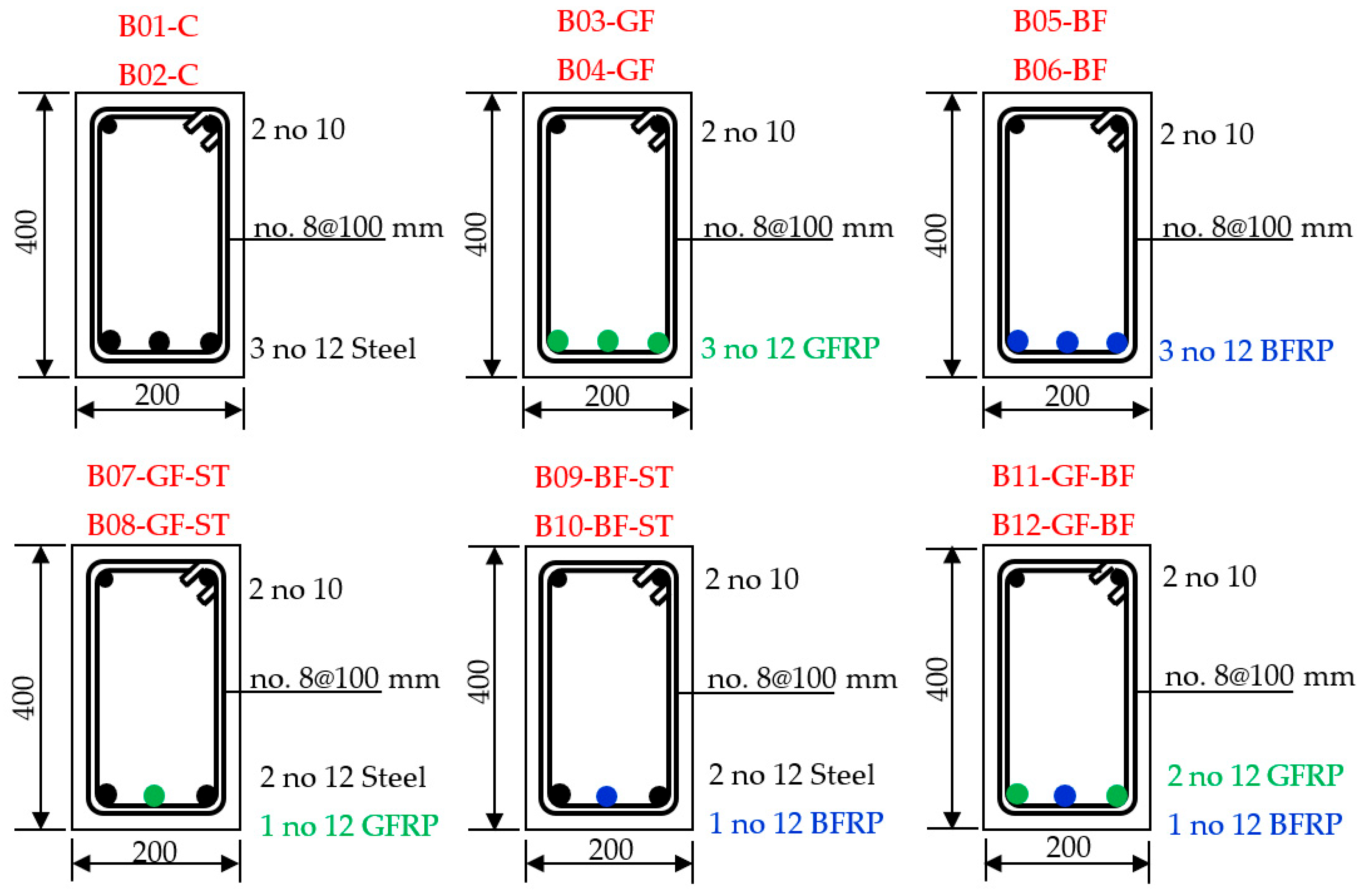
Figure 2.
Casting and curing the beams.
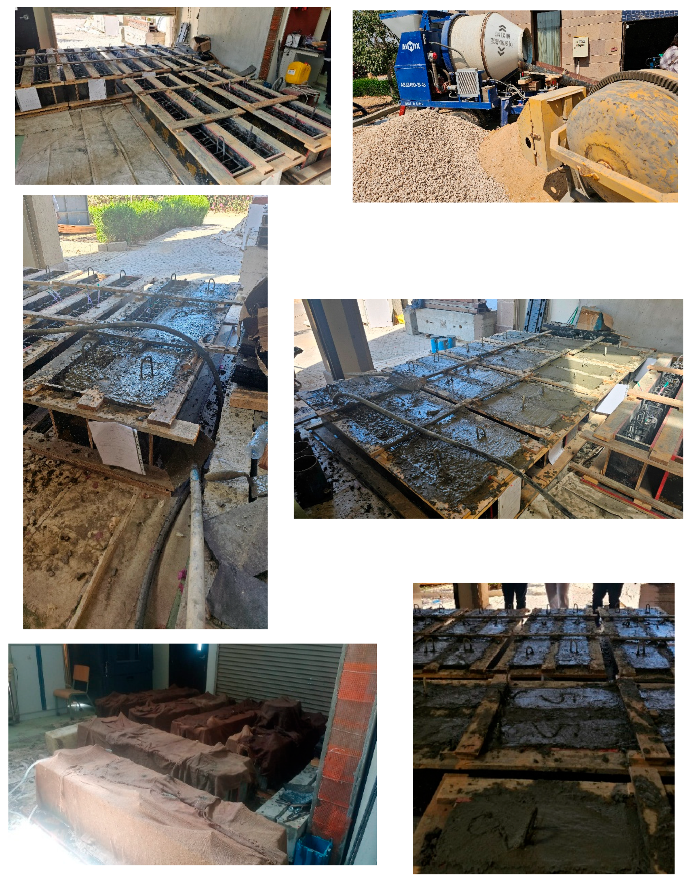
Figure 3.
Tests performed on fresh concrete.
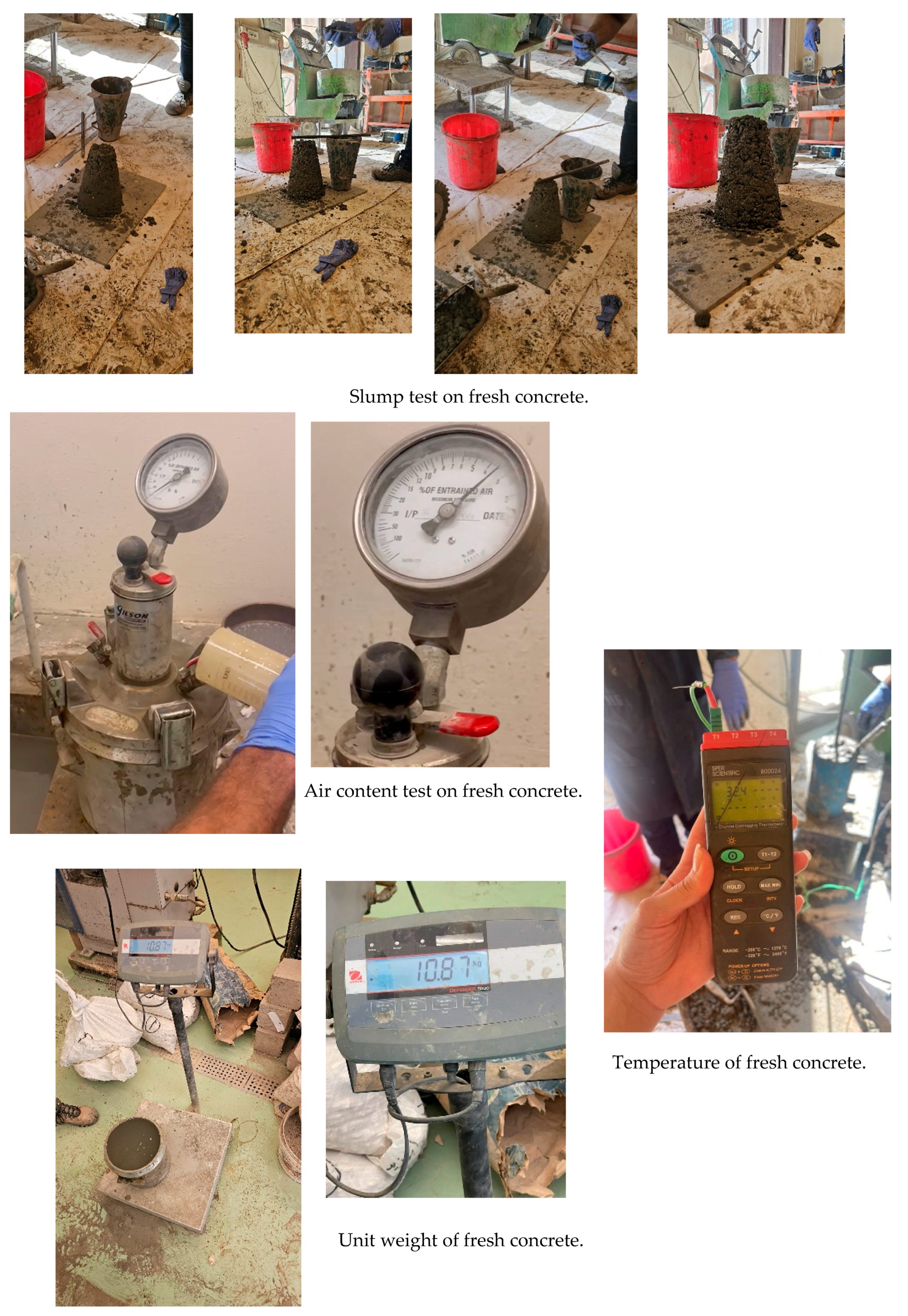
Figure 4.
Uniaxial tension tests performed on the 12 mm (left) and 8 mm (right) bars used for flexure and shear reinforcement.
Figure 4.
Uniaxial tension tests performed on the 12 mm (left) and 8 mm (right) bars used for flexure and shear reinforcement.
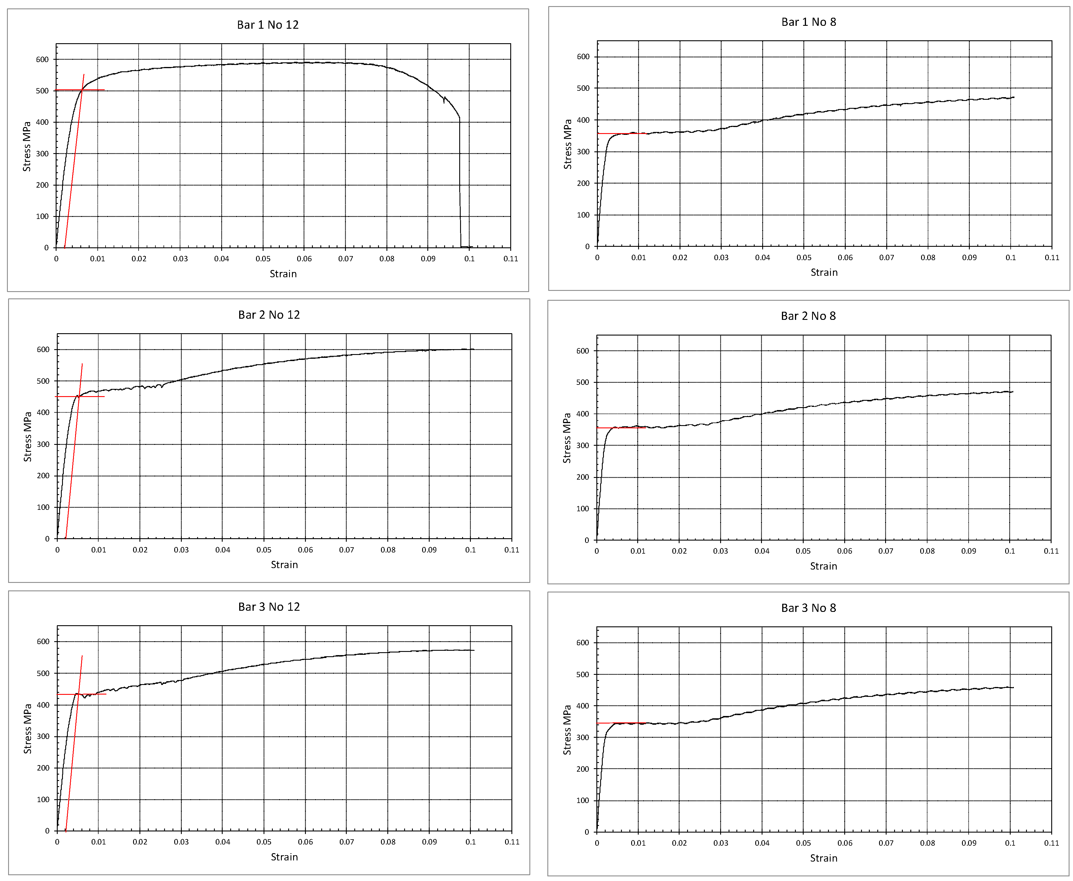
Figure 5.
Uniaxial tension tests performed on the 8 mm GFRP bars (left) and 10 mm BFRP bars (right) used for flexure reinforcement.
Figure 5.
Uniaxial tension tests performed on the 8 mm GFRP bars (left) and 10 mm BFRP bars (right) used for flexure reinforcement.
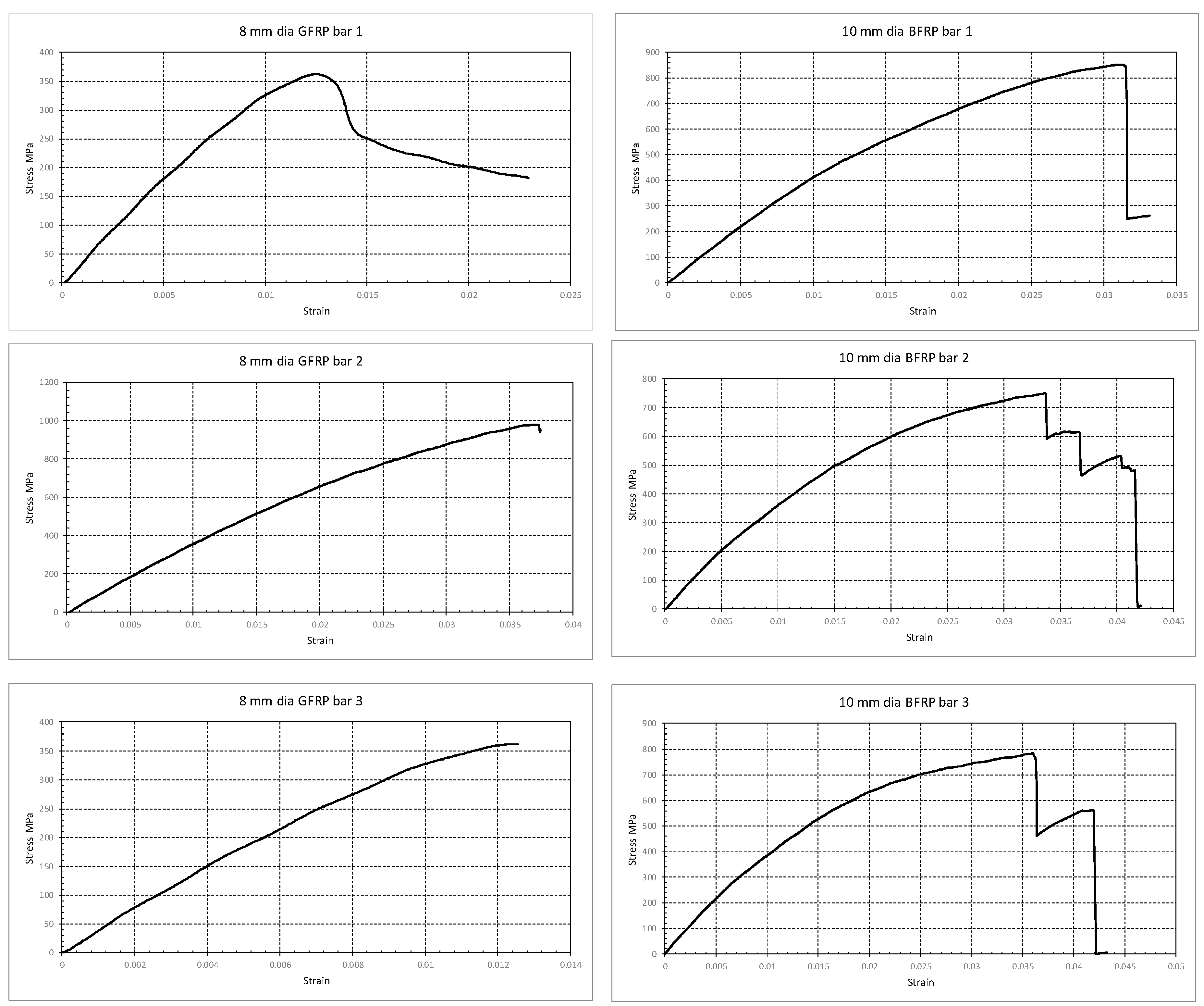
Figure 6.
Test set-up and instrumentation.
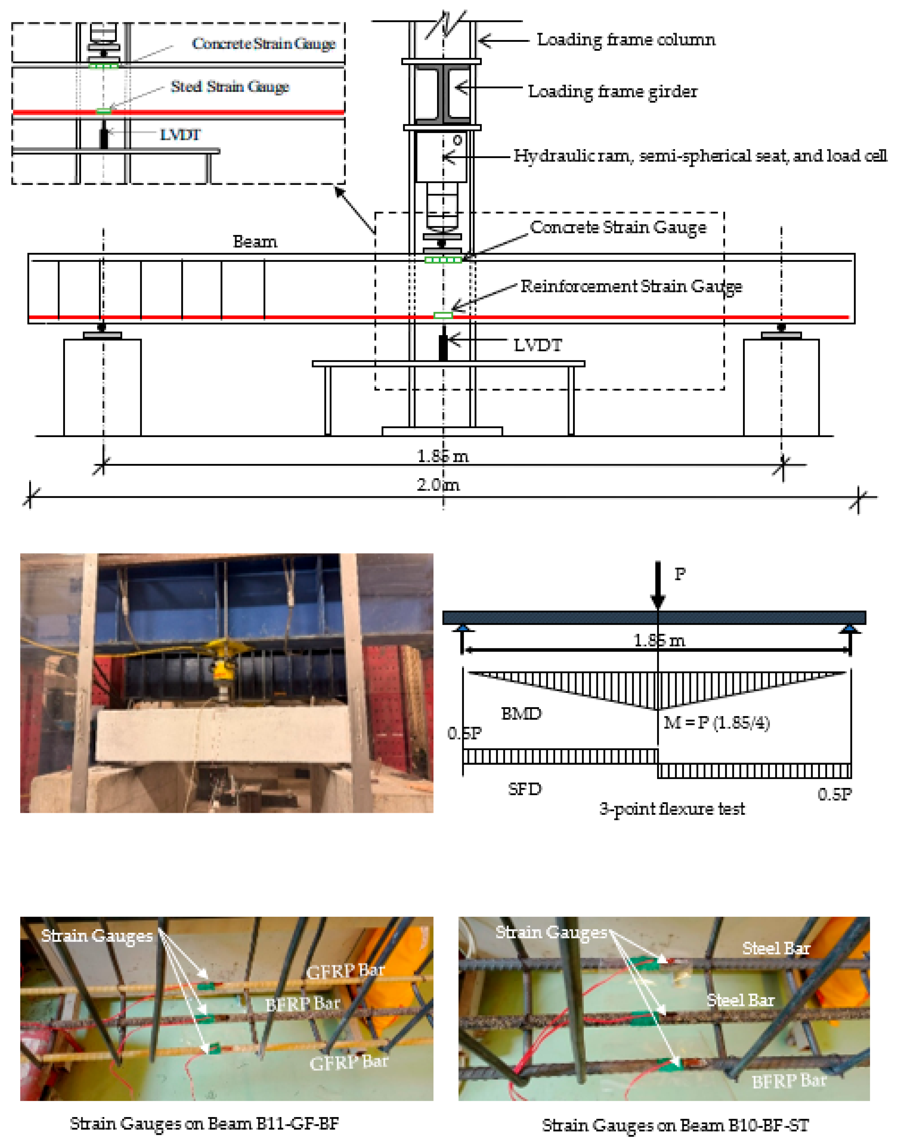
Figure 7.
Distribution of stress and strains for nominal moment calculations
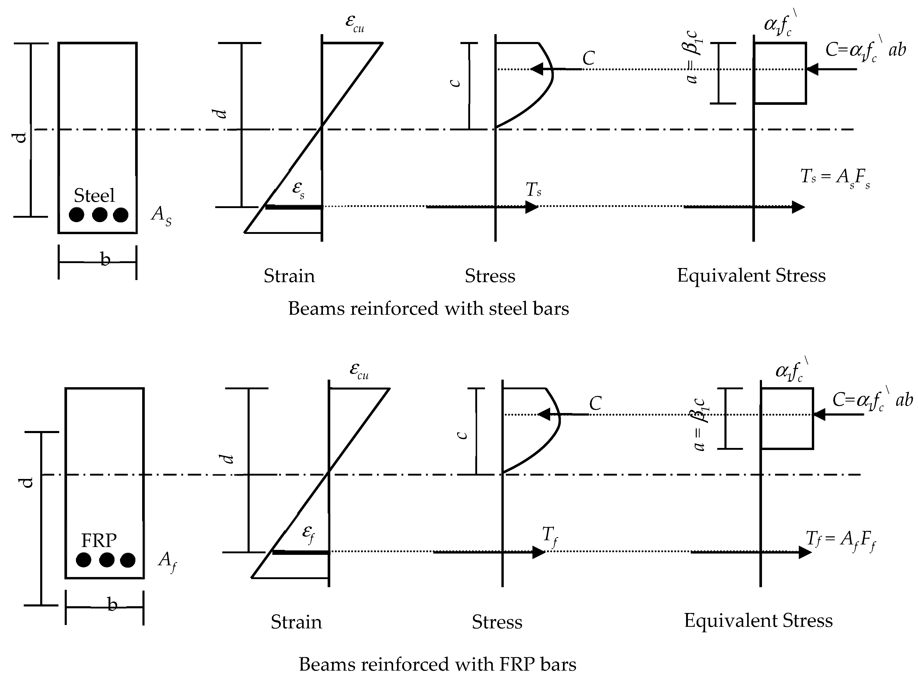
Figure 8.
Cracking patterns and failure modes of the tested beams.
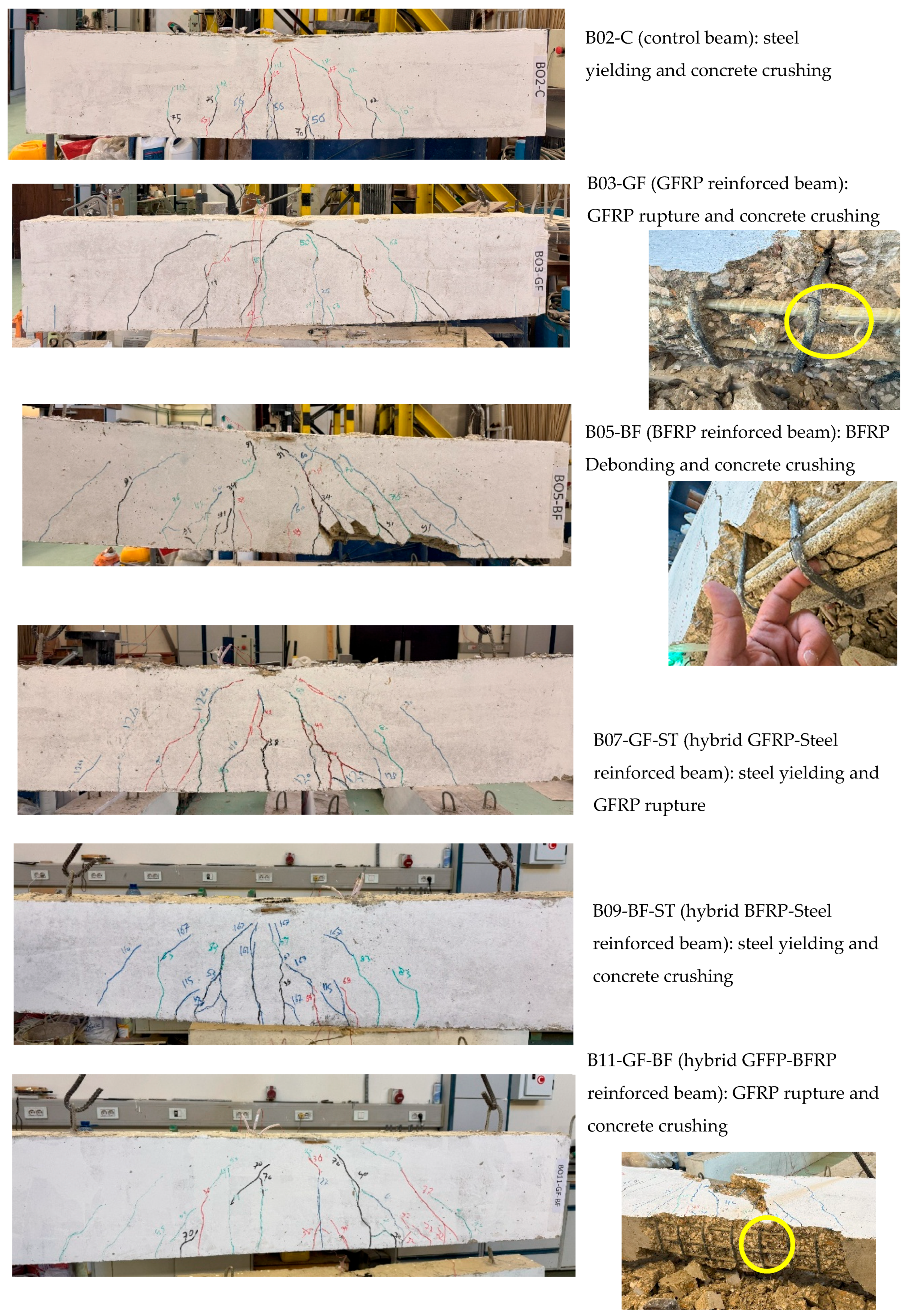
Figure 9.
Load defection recorded for all tested beams and the adopted ductility index.
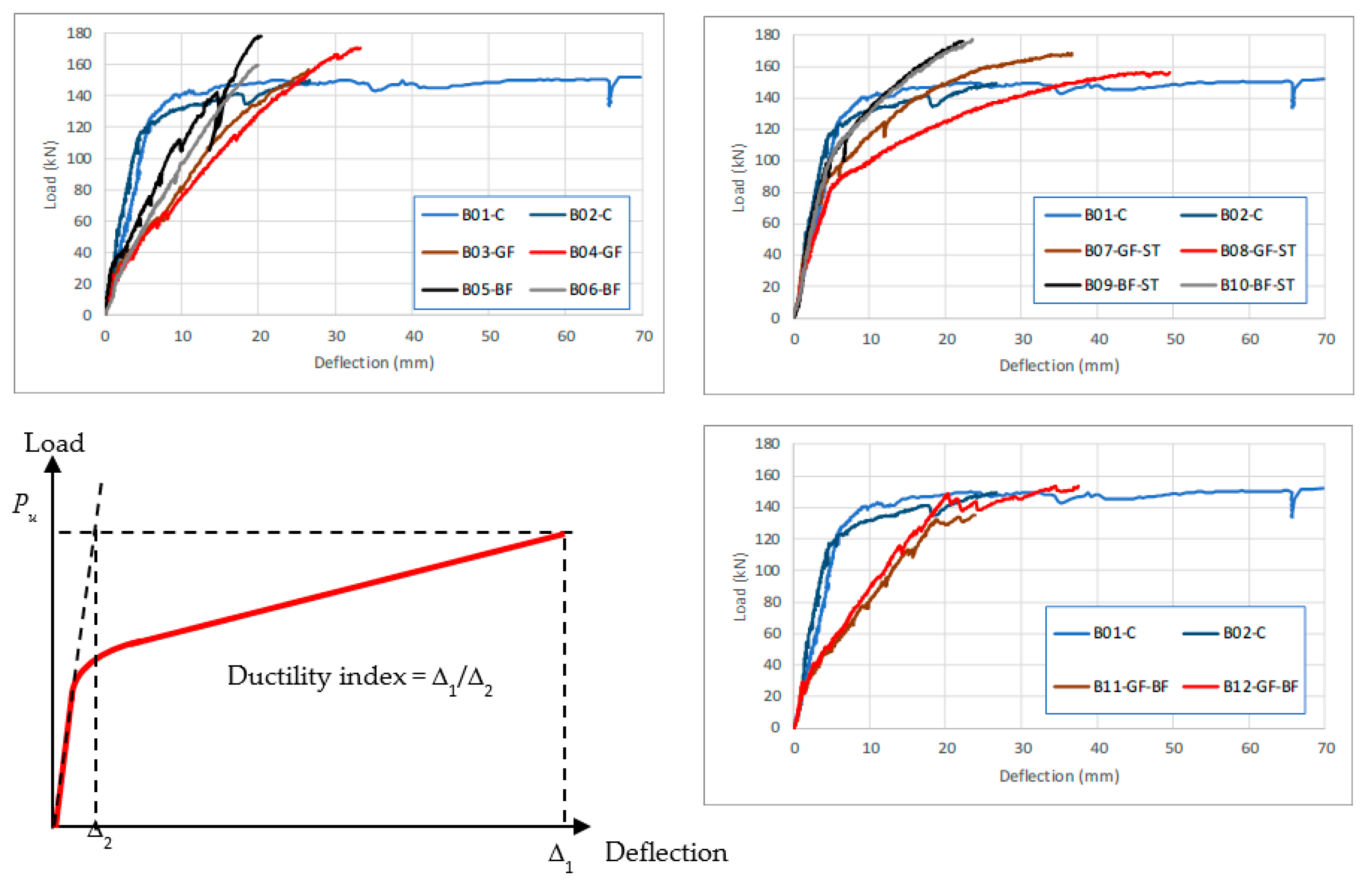
Figure 10.
Concrete compression strain measurements for all the tested beams.
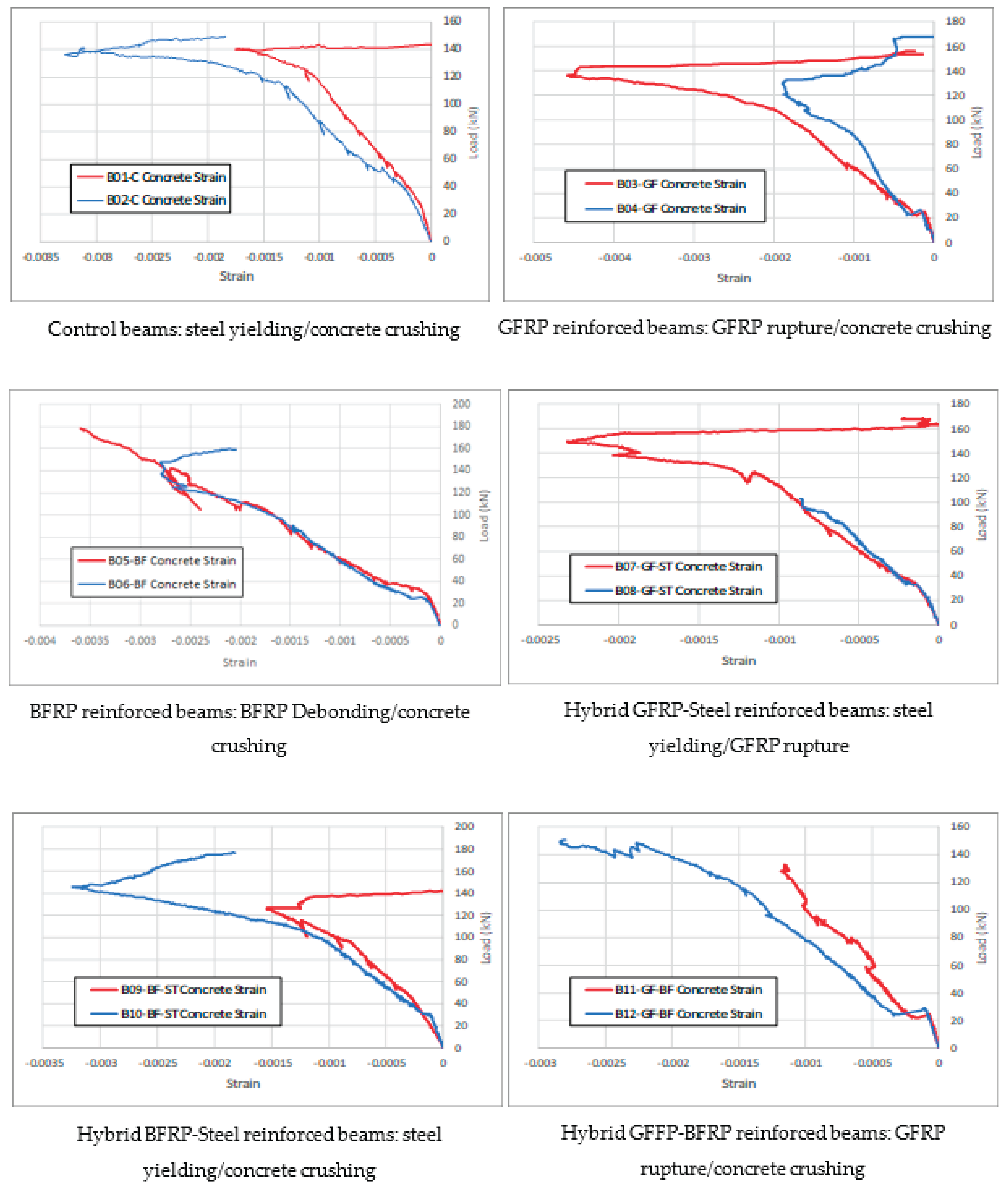
Figure 11.
(a) Reinforcement tensile strain measurements for all the tested beams. (b) Reinforcement tensile strain measurements for all the tested beams.
Figure 11.
(a) Reinforcement tensile strain measurements for all the tested beams. (b) Reinforcement tensile strain measurements for all the tested beams.
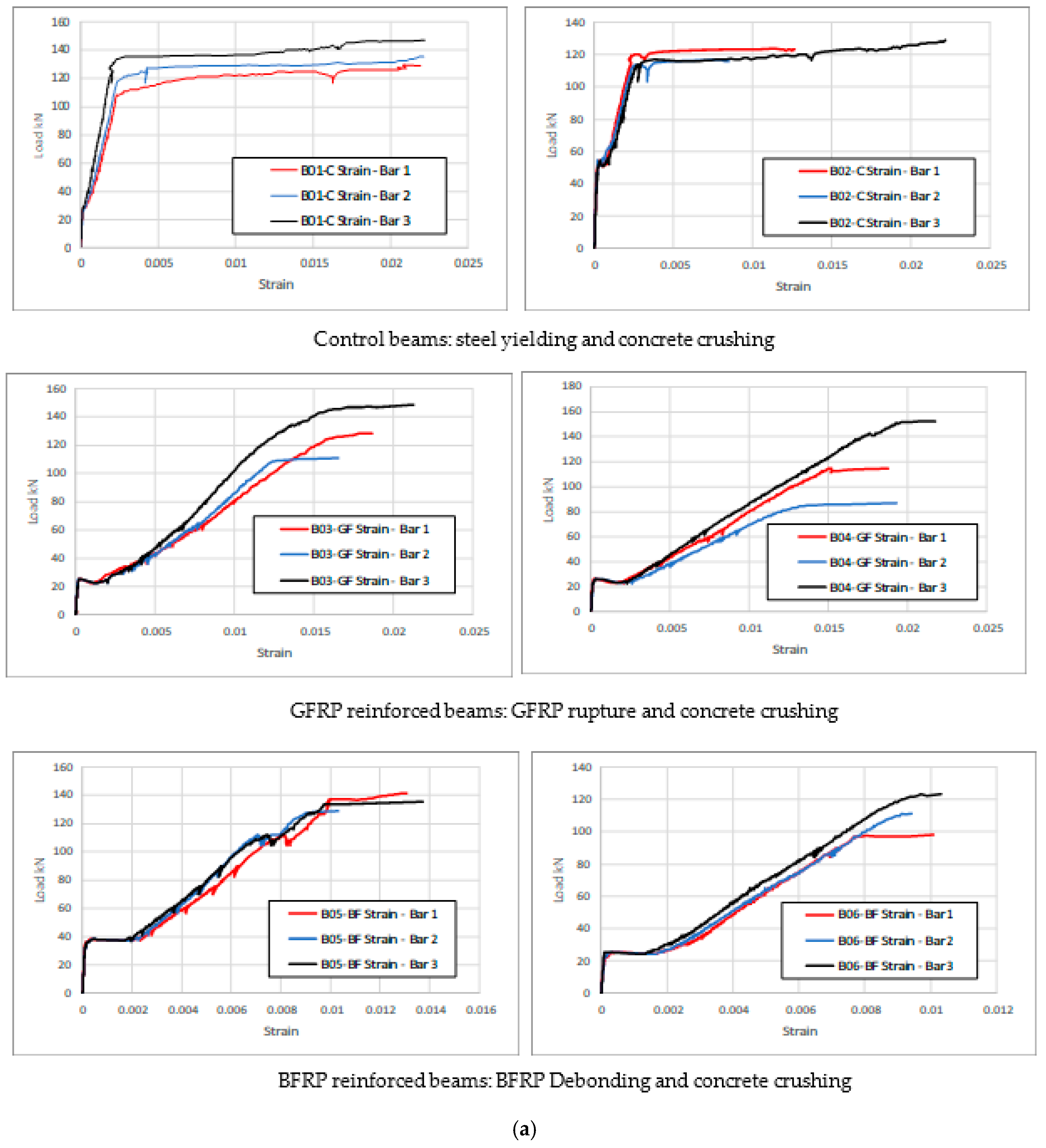


Table 1.
Details of the tested beams.
| Beam | Bottom Reinf | Top Reinf | Stirrups | Length (m) | Dim (mm) | ||
|---|---|---|---|---|---|---|---|
| B01-C B02-C |
3 no 12 | Steel | 2 no 10 | Steel | no 8@100 mm | 2.0 | 200×400 |
| B03-GF B04-GF |
3 no 12 | GFRP | 2 no 10 | steel | no 8@100 mm | 2.0 | 200×400 |
| B05-BF B06-BF |
3 no 12 | BFRP | 2 no 10 | steel | no 8@100 mm | 2.0 | 200×400 |
| B07-GF-ST B08-GF-BF |
2 no 12 1 no 12 |
Steel GFRP |
2 no 10 | Steel | no 8@100 mm | 2.0 | 200×400 |
| B09-BF-ST B10-BF-ST |
2 no 12 1 no 12 |
Steel BFRP |
2 no 10 | Steel | no 8@100 mm | 2.0 | 200×400 |
| B11-GF-BF B12-GF-BF |
2 no 12 1 no 12 |
GFRP BFRP |
2 no 10 | Steel | no 8@100 mm | 2.0 | 200×400 |
Table 2.
Mechanical properties of concrete, steel, GFRP, and BFRP.
| Material | Property | Value |
|---|---|---|
| Concrete | 28d compressive strength: fc/ | 25 MPa |
| Crushing strains εcu | 0.003 | |
| Initial elastic modulus Ec =4700 (fc/)1/2 | 23.5 GPa | |
| α1 and β1 | 0.85, 0.85 | |
| Steel bars | Yield stress Fy-s – reinforcement bars Yield stress Fy-v – stirrups |
465 MPa 360 MPa |
| Elastic modulus Es | 200 GPa | |
| Yield strain εy-s – reinforcement bars Yield strain εy-v – stirrups |
0.0023 0.0018 |
|
| GFRP bars | Tensile strength Fu-GFRP | 483 – 690 MPa |
| Elastic modulus EGFRP | 35 – 61 GPa | |
| Rupture strain εu-GFRP | 0.01 – 0.031 | |
| BFRP bars | Tensile strength Fu-BFRP | 600 – 1700 |
| Elastic modulus EBFRP | 50 – 90 GPa | |
| Rupture strain εu-BFRP | 0.018 – 0.032 |
Table 3.
Analytical investigation results.
| Beam | Nominal moment Mn (kN·m) | Expected failure load Pu-M (kN) | Failure mode analytically predicted |
Nominal shear Vn (kN) |
Expected failure load Pu-V (kN) |
|---|---|---|---|---|---|
| B01-C B02-C |
55.5 | 120 | Steel yield – Conc crushing | 197 | 393 |
| B03-GF B04-GF |
80.9 | 175 | GFRP rupture – Conc crushing | 154 | 308 |
| B05-BF B06-BF |
92.9 | 201 | Conc crushing | 157 | 314 |
| B07-GF-ST B08-GF-ST |
62.4 | 135 | Steel yield – GFRP rupture | 197 | 393 |
| B09-BF-ST B10-BF-ST |
76.7 | 166 | Steel yield – Conc crushing | 197 | 393 |
| B11-GF-BF B12-GF-BF |
92.1 | 199 | GFRP rupture – Conc crushing | 197 | 393 |
Table 4.
Experimental investigation results.
| Beam | Calc. failure load (kN) | Expected Failure Mode | Experimental failure load (kN) |
Deflection at failure (mm) | Observed Failure Mode | Capacity increase% | ||
|---|---|---|---|---|---|---|---|---|
| 0B01-C B02-C |
120 | Steel yield – Conc crushing | 152.2 149.5 |
150.8 ± 1.9 | 69.8 26.5 |
48.2 ± 30.6 | Steel yield – Conc crushing | -- |
| B03-GF B04-GF |
175 | GFRP rupture – Conc crushing | 156.4 170.6 |
163.5 ± 10.1 | 26.6 33.2 |
29.9 ± 4.7 | GFRP rupture – Conc crushing | 8% |
| B05-BF B06-BF |
201 | Conc crushing | 178.2 159.5 |
168.9 ± 13.2 | 20.4 19.9 |
20.2 ± 0.4 | BFRP debond – Conc crushing | 12% |
| B07-GF-ST B08-GF-ST |
135 | Steel yield – GFRP rupture | 168.7 156.4 |
162.6 ± 8.7 | 36.7 49.5 |
43.1 ± 9.1 | Steel yield – GFRP rupture | 8% |
| B09-BF-ST B10-BF-ST |
166 | Steel yield – Conc crushing | 176.3 177.5 |
179.9 ± 0.85 | 22.3 23.6 |
23.0 ± 0.9 | Steel yield – Conc crushing | 17% |
| B11-GF-BF B12-GF-BF |
199 | GFRP rupture – Conc crushing | 135.4 153.7 |
144.6 ± 12.9 | 23.8 37.5 |
30.7 ± 9.7 | GFRP rupture – Conc crushing | -4% |
Table 5.
Ductility index toughness of the tested beams.
| Beam | Δ1 (mm) | Δ2 (mm) | DI = Δ1/Δ2 | A (kN·m) | A/Acontrol | |||
|---|---|---|---|---|---|---|---|---|
| 0B01-C B02-C |
70 26.5 |
48.3±30.8 | 8.0 5.1 |
6.6±2.1 | 7.4 | 11.03 3.29 |
7.2±5.5 | 1.00 |
| B03-GF B04-GF |
26.7 33.1 |
29.9±4.5 | 6 7.6 |
6.8±1.1 | 4.4 | 2.52 3.37 |
2.9±0.6 | 0.41 |
| B05-BF B06-BF |
20.5 20 |
20.3±0.4 | 4.5 8.4 |
6.5±2.8 | 3.1 | 2.11 1.22 |
1.7±0.63 | 0.23 |
| B07-GF-ST B08-GF-ST |
36.8 49.8 |
43.3±9.2 | 4.6 6.2 |
5.4±1.1 | 8.0 | 3.29 5.92 |
4.6±1.9 | 0.64 |
| B09-BF-ST B10-BF-ST |
22.4 23.8 |
23.1±1.0 | 3.7 6.2 |
5.0±1.8 | 4.7 | 2.91 3.02 |
2.9±0.1 | 0.41 |
| B11-GF-BF B12-GF-BF |
23.8 23.7 |
23.8±0.07 | 5.1 6.5 |
5.8±1.0 | 4.1 | 2.16 4.38 |
3.3±1.6 | 0.45 |
Disclaimer/Publisher’s Note: The statements, opinions and data contained in all publications are solely those of the individual author(s) and contributor(s) and not of MDPI and/or the editor(s). MDPI and/or the editor(s) disclaim responsibility for any injury to people or property resulting from any ideas, methods, instructions or products referred to in the content. |
© 2025 by the authors. Licensee MDPI, Basel, Switzerland. This article is an open access article distributed under the terms and conditions of the Creative Commons Attribution (CC BY) license (http://creativecommons.org/licenses/by/4.0/).
Copyright: This open access article is published under a Creative Commons CC BY 4.0 license, which permit the free download, distribution, and reuse, provided that the author and preprint are cited in any reuse.


