
Submitted:
23 May 2025
Posted:
23 May 2025
You are already at the latest version
Abstract
This paper presents LokAlp, a modular timber construction system invented and developed by the authors, inspired by the traditional Blockbau technique and designed for circularity and self-construction. LokAlp utilizes standardized interlocking blocks fabricated from CLT and GLT off-cuts to optimize material reuse and minimize waste. The research evaluates geometric adaptability, production feasibility, and on-site assembly efficiency within a computational design and digital fabrication workflow. The definition of the Lokalp system has gone through several iterations. A full-scale demonstrator constructed using the LokAlp final iteration (Mk. XII) incorporated topological enhancements, increasing connection variety and modular coherence. Comparative analyses of subtractive manufacturing via 6-axis robotic milling versus traditional CNC machining revealed a >45% reduction in cycle times with robotic methods, indicating significant potential for sustainable industrial fabrication; however, validation under operational conditions is still required. Augmented reality-assisted assembly improved accuracy and reduced cognitive load compared to traditional 2D documentation, enhancing construction speed. Overall, LokAlp demonstrates a viable circular and sustainable construction approach combining digital fabrication and modular design, warranting further research to integrate robotic workflows and structural optimization.
Keywords:
mass timber construction
; construction waste reuse
; design for disassembly
; discrete architecture
; self-build practices
; circular economy
; augmented reality
; reconfigurable building systems
; computational design
; digital fabrication
1. Introduction
Self-construction, traditionally associated with informal processes, is re-emerging today in an updated form within new modular construction systems, where the user actively participates in assembly through explicit construction rules. This new scenario, enabled by computational design and digital fabrication, allows the self-builder to interact with discrete elements designed to be reconfigurable, accessible, and sustainable.
In recent years, architectural research has outlined an emerging paradigm centered on open modular construction systems, where components are no longer conceived as functionally specialized elements but as digital materials [1]. Unlike traditional modular solutions - characterized by elements with static and non-reconfigurable functions, for example in the distribution of vertical or horizontal loads - digital materials are elementary units without intrinsic function, equipped with a finite number of reversible connections that allow aggregation according to a topological logic. These units operate within a framework of open modularity [2], understood not as a predefined configuration but as a set of rules that permits the addition or removal of parts without compromising the overall systemic coherence.
This approach substantially diverges from the classical concept of architectural modularity, which is based on the juxtaposition of heterogeneous and function-specific components. In systems based on digital materials, the function of each element is determined solely by its relative position and topological configuration within the aggregate [3,4], enabling high reconfigurability starting from a limited set of standardized components.
The adoption of digital materials in open construction systems enables significant advantages in both economic and environmental terms, leveraging the benefits of standardization and serial manufacturing to reduce waste and optimize resource use. In this context, architectural customization is not achieved through the mass customization of individual components, but rather through aggregation strategies that generate differentiated morphologies from identical units.
This paradigm aligns with the principles of Design for Disassembly and Reuse (DfDR), supporting a fundamentally more sustainable vision of the built environment: no longer as a static and consumptive end-product, but as a dynamic, circular repository of reconfigurable material. The ability to disassemble and reassemble components into new spatial and functional configurations not only overcomes the structural and formal rigidities of conventional modular systems, but also extends the lifecycle of materials, facilitates their reintegration into new constructions, and reduces the environmental impact associated with demolition and new production.
1.1. Limitations of Current Open Modular Systems
Open modular wood-based construction systems developed so far at a 1:1 demonstrator prototype scale generally exhibit recurring design configurations in typological and structural terms. Specifically, the literature and practical experimentation have shown a predominance of configurations definable as lightweight structural systems, i.e., linear skeletal systems in which loads are transmitted exclusively through linear elements [5]. These structures are characterized by high spatial permeability and low material density, where voids prevail over mass.
The state-of-the-art analysis conducted by Retsin [6], investigating the architectural trend related to these open timber modular systems, highlighted that much of the academic research has favored timber structural systems capable of discretizing particularly complex geometries, often involving demonstrative pavilions. The primary objective of these construction systems, however, concerned mainly the demonstration and validation of parallel and complementary technologies, rather than the direct application of these systems in conventional building contexts.
Different discrete systems have demonstrated, in fact, the use of augmented reality for assisted assembly [7], the employment of virtual environments for simulating construction processes [6], or the integration of modular robots for automated assembly [8], focusing future outlooks on the merits of these technologies rather than on the projection of construction systems into permanent building contexts.
1.2. Reuse of CLT and GLT By-Products in Open Modular Systems
Open modular wood-based construction systems developed to date predominantly employ first-processing engineered wood, particularly non-structural multilayer panels such as plywood or three-layer panels. The potential use of by-products derived from the mass engineered wood production chain - such as Cross-Laminated Timber (CLT) and Glued-Laminated Timber (GLT) - represents a significant opportunity to improve the environmental performance of building systems, especially within a circular economy framework aimed at reducing climate-altering emissions [9]. This application domain, still scarcely investigated in the scientific literature on open modular construction systems, constitutes a strategic nexus for transitioning toward more sustainable and resilient construction models.
In the industrial production process of CLT, substantial waste is generated, mainly from the re-cutting required to create openings for doors and windows. In the European context, such by-products can represent up to 20% of the total panel volume processed [10], while in the United States, estimates range around 15% [11]. Currently, these materials are predominantly destined for energy recovery processes or incineration, since the presence of industrial adhesives prevents landfill disposal and hinders biodegradation [12]. These valorization methods clearly represent a downcycling process: a material with high mechanical performance and significant technological complexity is downgraded to a low-value energy source, resulting in loss of embedded value within the production chain and the generation of climate-altering CO₂ emissions.
For GLT beams, technical studies have highlighted the systematic presence of off-cuts generated during distribution [13]. GLT beams are commonly produced in standard lengths between 14 and 17 meters and subsequently cut at distribution centers to meet the dimensional requirements of residential building applications, which often require significantly shorter lengths. This process frequently leaves residual pieces with typical cross-sections of 130×160 mm and lengths under 4 meters, which are not destined for specific structural use. However, these off-cuts still retain the mechanical properties of the original product.
Although some virtuous case studies confirm the technical feasibility of employing by-products derived from CLT production within building systems [14], such approaches do not strictly adhere to the discrete logic. Rather, they rely on principles of mass customization of individual components, thus forsaking one of the fundamental premises of open modularity: the replicable and combinatorial standardization of construction units. Within research on discrete modular systems, the use of industrial residues has been primarily limited to lightweight, non-structural three-layer panels employed in lightweight discrete structural systems configurations [15], without fully exploring the potential offered by reusing massive structural elements such as CLT or GLT.
1.3. Research Objectives
As analyzed in the previous Section 1.1, nearly all timber digital materials developed to date have been conceived according to structural logics attributable to lightweight structural systems. Such systems have generally been tested exclusively at the pavilion scale, significantly limiting the exploration of their use in ordinary architectural-scale building contexts, as observed by Oosterhuis [16].
The objective of this research is to develop, within the realm of discrete architecture, a timber construction system that critically departs from the prevailing approach, proposing a massive paradigm inspired by traditional European Blockbau techniques [17]. This European massive timber construction system can be partially interpreted considering the principles of the digital material concept, as its components are characterized by an intrinsically informative geometry that enables their deconstruction and subsequent reuse without loss of integrity. A paradigmatic example of this logic is the 1966 deconstruction and reconstruction of a Blockbau building originally constructed in the 15th century [18]. This intervention was executed without damaging the wooden elements, which were disassembled, transported, and reassembled at a new site located at a higher altitude, demonstrating the system’s full reversibility and reusability.
Unlike multiple studies focusing on discretizing complex geometries, the system proposed here aims to reproduce ordinary multi-story living spaces and to construct building components such as load-bearing walls, columns, beams, and floors.
By reinterpreting the Blockbau construction technique through computational design and digital fabrication tools, the developed system must guarantee the possibility to generate continuous load-bearing walls free from material discontinuities, while preserving the discrete logic of assembly.
An additional objective of this work is to demonstrate the feasibility of a more efficient and sustainable use of off-cuts generated by the CLT and GLT industry, integrating them within the context of discrete architecture. Considering that digital materials operate as architectural voxels for space discretization and thus, by definition, possess dimensions smaller than conventional building elements, it is possible to reuse cutting waste produced during the processing of CLT panels (particularly off-cuts generated by door and window openings) and GLT beam off-cuts for the fabrication of such construction components. This approach aims to preserve the added value of engineered wood in terms of structural performance, avoiding the typical downcycling associated with energy recovery.
2. Methodology
2.1. The LokAlp System
LokAlp is a dry-assembly design and construction system based on the use of standardized modular wooden blocks. This series of components enables the creation of various building elements - such as beams, columns, walls, and floors - through aggregative logics that ensure compositional versatility and geometric coherence. The morphological and functional definition of the discrete “LokAlp” block was guided by a set of integrated design parameters, which accounted for both the compositional potential of the system and the constraints deriving from the use of wood off-cuts such as CLT panels and GLT beams.
The block design was conceived following a spatial discretization logic based on a cubic matrix, assuming that system modularity could emerge from the repetition and combination of regular units. Within this logic, the block’s short side was defined based on the maximum thickness recoverable from available wood off-cuts, generally ranging between 100 and 160 mm, in accordance with the average thickness values of load-bearing CLT walls used in buildings from three to eight stories [19]. The overall block length was determined as a multiple of the short side, thus maintaining coherence with the three-dimensional cubic grid and ensuring the spatial composability of the system.
During the design phase, the main challenges involved defining formal and technical solutions to guarantee the realization of 90-degree corner nodes without protruding elements, configuring three-way joints for beam-column integration, and enabling openings within walls for door and window insertion. Another key design issue concerned optimizing the number and type of possible connections for each block. Excessive junction variety would have certainly increased compositional freedom but would have also significantly raised fabrication waste, reducing the efficiency of reusing engineered wood by-products.
The maximum block weight was set at 10 kg, in compliance with ISO 11228-1:2003 and EN 1005-2 standards regulating manual load handling according to frequency, duration, distance, and operational conditions. According to these standards, a 10 kg load can be manually handled up to a maximum frequency of approximately seven lifts per minute, only if the activity duration is intermittent and ranges between one and two hours. Considering a reasonable transport distance of four meters - a representative value for movement between the component storage area and the assembly site - the maximum load that can be manually handled over an eight-hour workday is estimated at around 10,000 kg, with a handling frequency not exceeding two cycles per minute [20].
The entire design process led to the definition and prototyping of fifteen constructive variants of the system, named “Mark” and numbered progressively (Figure 1). Their main morphological and functional characteristics are summarized in Table 1. The 15 developed 3D prototypes, along with detailed descriptions of their assembly potential, are openly accessible via the repository indicated in the Data Availability Statement to allow verification, reproduction, and reuse for scientific purposes [21].
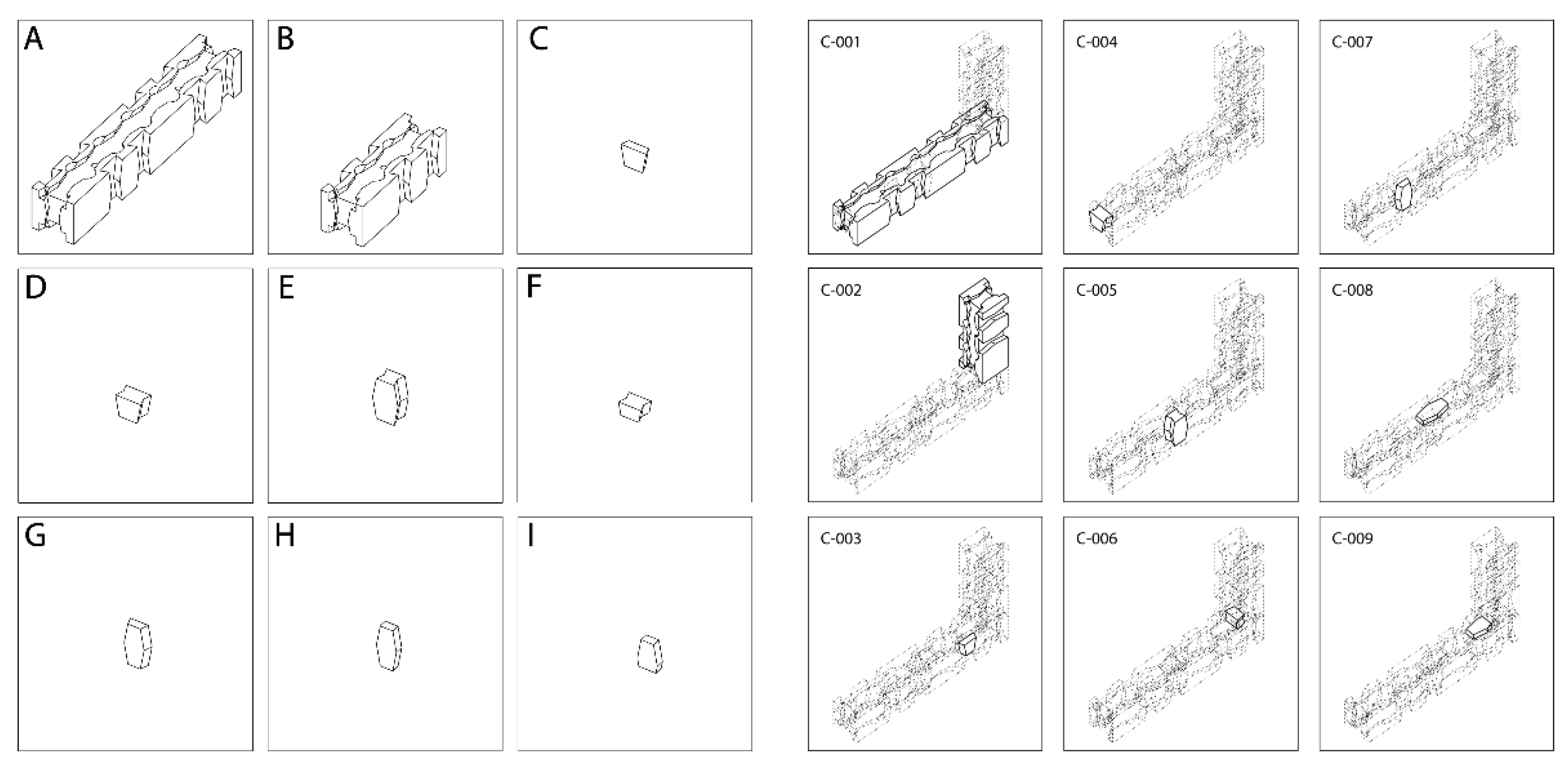
2.2. Assembly Logic of the LokAlp Mk. XII System
The LokAlp Mk. XII system is based on two modular types of building blocks, designated A and B (Figure 3). Both blocks share a square base cross-section but differ solely in length. Block A has a length equal to six times the side of the square, while block B measures three times the same side, exactly half the length of block A. The geometric proportions between blocks A and B must remain constant regardless of the initial side length chosen as the reference unit.
Block assembly occurs through specific connectors called biscuits (components C–I) (Figure 3), which constitute the sole means of creating connections between modular elements. Blocks A and B can be interconnected in any combination using the biscuits (A–A, B–B, A–B, B–A), but biscuits cannot connect to each other. Biscuits C–G perform the primary junction function between blocks, whereas biscuits H and I act solely as passive locking elements for biscuits C–G and do not independently enable block-to-block connections.
Each block A can accommodate up to 22 simultaneous connections with other blocks A or B (Figure 2), while block B can accommodate up to 12. The grooves present on all six faces of blocks A and B, characterized by variable but internally uniform inclinations and depths, directly influence the geometry of the biscuits but do not affect the number or type of possible connections. Therefore, parametric variation of the grooves does not alter module compatibility nor the combinatorial flexibility of the system.
Figure 2.
Overview of the main assembly possibilities of the LokAlp Mk. XII System.
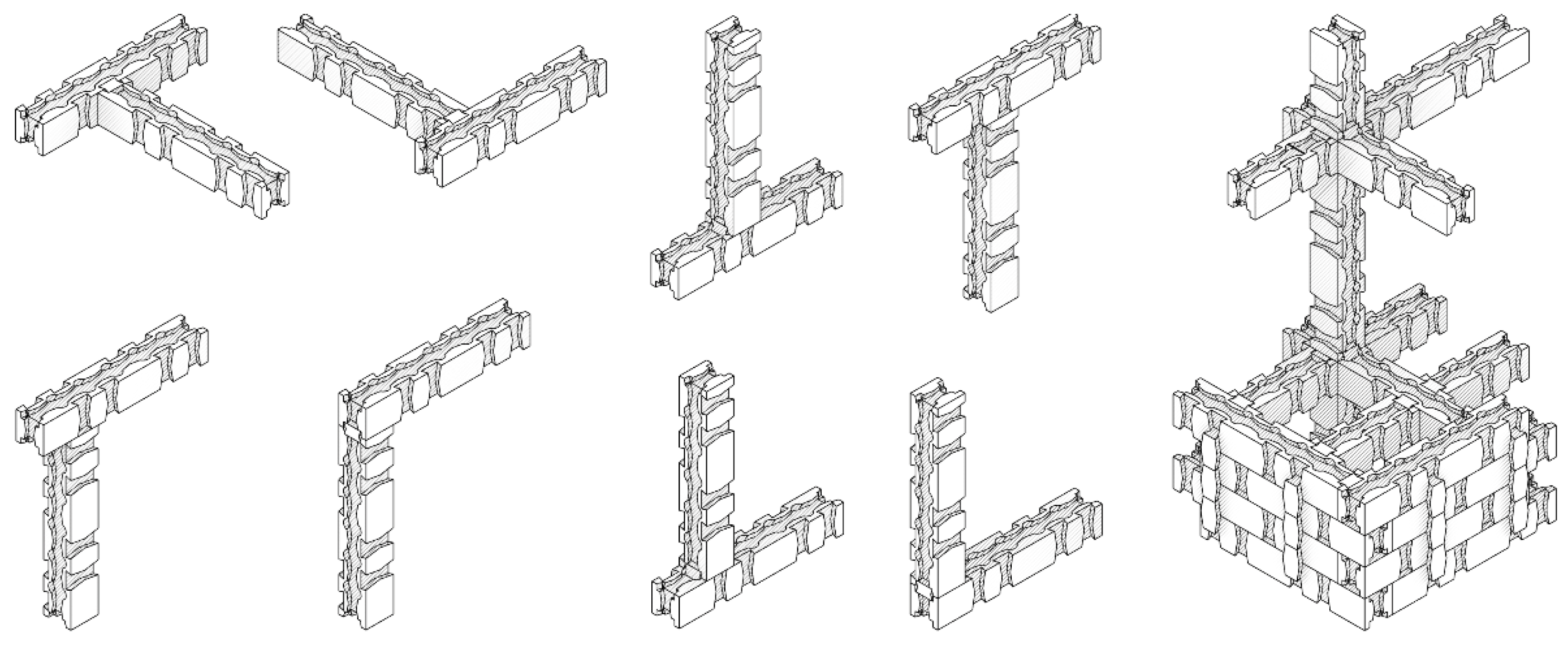
Figure 3.
Overview of the nine components forming the LokAlp Mk. XII construction system, including the two building blocks (A–B) and seven connectors (C–I). Each element is designed to fulfill specific structural or assembly functions. On the right: example of practical application of the LokAlp Mk. XII connectors in a standard configuration.
2.3. Computational Design
Starting from the LokAlp Mk V block version, a parametric design system based on the Grasshopper3D framework [22] was introduced with the goal of optimizing the management of geometric variables during iterative development phases. The integration of computational design tools played a strategic role, particularly in enhancing the efficiency of the transition from modeling to production. The ability to modify the generative parameters of the block in real time made the operational workflow highly responsive, following a file-to-factory logic that directly connects the digital 3D model with physical fabrication processes.
In addition to supporting 3D printing of 1:10 scale models during prototype validation stages, the parametric system facilitated coordination with the partner carpentry company, helping to manage technical uncertainty related to tool availability. Specifically, the type of dovetail cutter mounted on the machining center to be used later was not definitively determined until the final phases of the project, necessitating a sufficiently flexible modeling approach able to adapt to different tool geometries. The dynamic nature of the computational model enabled direct modifications to the milling cutter profile within the parametric environment without interruptions to the production flow, including the possibility of radical tool geometry substitutions during machining phases.
The parametric code was developed to operate without external input data and to guarantee an accessible user interface even for non-expert users. Its modular structure allows rapid generation of construction variants tailored to specific production constraints, configuring a highly resilient and replicable design environment. The parametric code and the detailed user manual are openly accessible via the repository indicated in the Data Availability Statement to allow verification, reproduction, and reuse for scientific purposes [21].
2.4. Design of the Architectural-Scale Demonstrator
To test the mechanical validity of the LokAlp system and verify its effectiveness during assembly, an architectural-scale demonstrator was designed and constructed, subsequently subjected to physical assembly tests. The configuration included elevated portions and cantilevered parts, aiming to explore different structural conditions. The design process was carried out using the WASP plug-in for Grasshopper3D [23], specifically oriented toward modeling discrete aggregations.
WASP represents a flexible solution for generating open modular aggregations within computational design. The framework allows explicit definition of both the geometry and topology of discrete units, establishing connection rules customizable by the designer. These rules are then used to automatically generate discrete aggregations based on predefined geometric constraints and assembly rules; the system also integrates tools to avoid collisions between elements.
In the case of the LokAlp Mk XII block “A” (Figure 3), the algorithm was programmed to recognize 44 theoretically possible combinations starting from a single generative element. However, once geometric and topological restrictions were applied, only 22 combinations were admissible for simultaneous aggregation.
For generating the final architectural demonstrator, spatial constraints defined through the Constraints module of the WASP plug-in were employed. These constraints can be formulated as geometric entities of different types - lines, planes, surfaces, and volumes - and act as spatial archetypes guiding the aggregation process. The computational system interprets these constraints as containment and orientation conditions, attempting to fill the available space as closely as possible through iterative distribution of the discrete elements constituting the digital material. The aggregation result obtained through the application of constraints is shown in Figure 4.
2.5. Production Using Hundegger CNC Work Center
The production phase of the LokAlp block was carried out in collaboration with a company specialized in timber carpentry for construction, experienced in processing GLT and CLT elements.
The blocks were manufactured using a Hundegger K2i machining center [24], a CNC machine designed for automated processing of architectural-scale wooden elements. This cutting center enables complex carpentry operations thanks to its technical equipment, which includes circular and horizontal saws (up to 13 kW) and a universal 5-axis milling machine with an industrial 35 kW spindle. The machine is designed for continuous production across three shifts, including handling large elements (up to 12 meters in length), making it suitable for large-scale prefabrication.
The LokAlp blocks were produced from spruce GLT beams with a square cross-section of 160 mm and a density of 450 kg/m³.
The entire production process represented a significant test bench to evaluate the limits and potentialities of employing an industrial cutting center in a non-serial, non-standardized context. The production facility and part of the dovetail milling operations are shown in Figure 5.
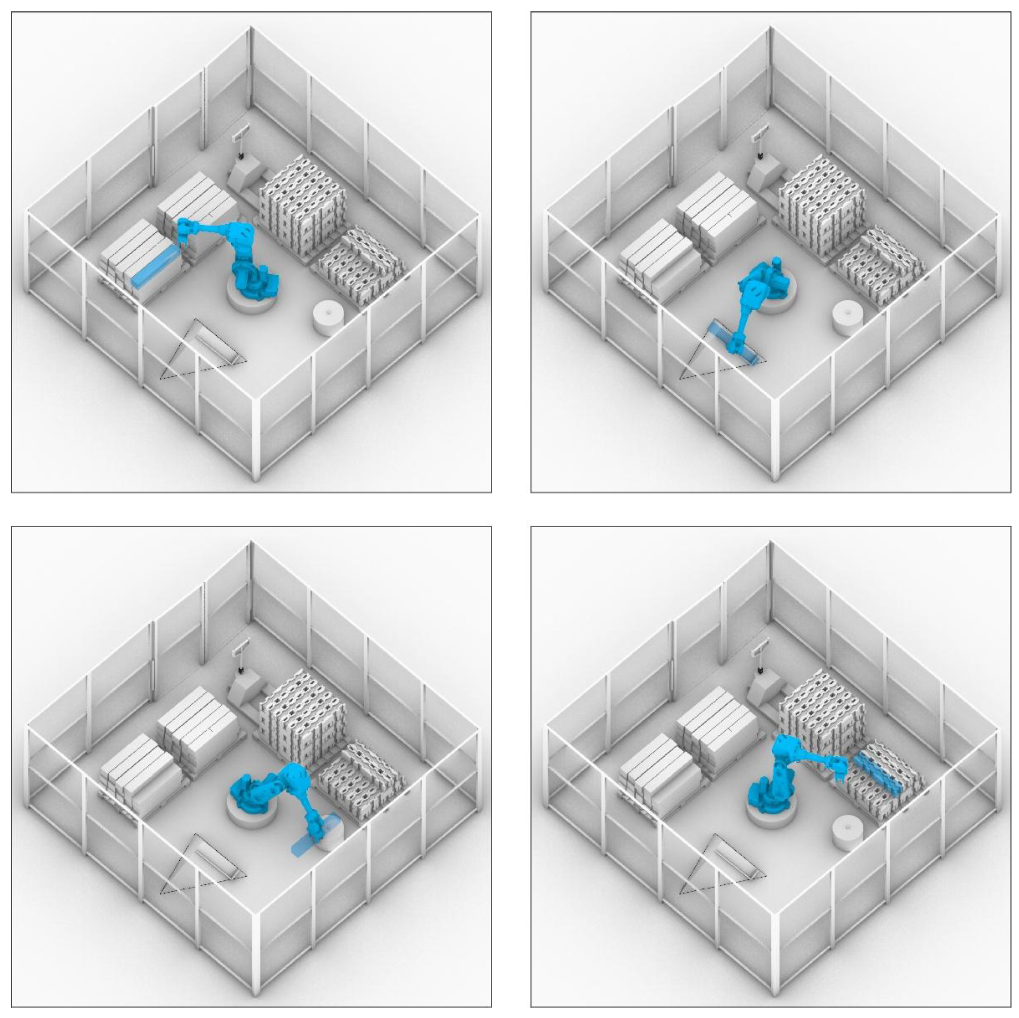
2.6. Robotic Simulation
In parallel with production using an industrial cutting center, a feasibility study was conducted on the use of industrial robotics as an alternative to conventional machinery (Hundegger machining centers).
The fabrication process was based on the use of a six-axis ABB IRB 4600 robotic arm, featuring a maximum payload of 20 kg and a reach of 2.5 meters. Motion programming was developed within the Grasshopper3D environment, enabling automatic generation of trajectories required both for pick-and-place operations and for sequential milling of all six faces of the block.
The robotic cell was designed including a centering plane, the ABB robotic arm, and a cutting plane. The centering plane is a three-axis inclined surface that allows the block to slide towards a fixed geometric reference, ensuring precision in the robot’s grasp. Knowing the exact position of the block within the robot’s coordinate system allows highly accurate operations without the need for further calibrations.
Once the robot grips the block, it transports it to the cutting plane following an optimized trajectory scripted in Grasshopper3D. After milling one face, the block is repositioned on the inclined plane and rotated by 90 degrees to allow machining of the next face. This cycle repeats until all six surfaces are completely processed, without operational interruptions or human intervention.
Figure 6.
Simulation of a robotic cell for the automated production of the LokAlp Mk. XII component. From left to right: gripping of the raw timber element, placement on the centering table, milling operations on the cutting table (including intermediate reorientations on the centering table), and final placement in the storage area of the finished component.
2.7. Assembly in Self-Build Context via Augmented Reality
The assembly of the discrete modular system was carried out through the implementation of an augmented reality (AR)-based workflow, using HoloLens 2 Industrial Edition smart glasses [25]. The integration was achieved via the “Fologram” [26] plug-in for Grasshopper3D, which enables real-time synchronization between the parametric modeling environment and the AR interface.
Through this system, all 367 assembly steps were encoded into an interactive digital interface: each new block or connector to be placed was highlighted using selective white illumination, while already positioned elements were displayed in a transparent mode.
3. Results
The final tectonic configuration developed for the production and assembly phases consisted of an architectural composition partially inspired by traditional blockbau timber systems, recalling the structural articulation of pillars and floor frames with primary and secondary beams. While this reference maintained realistic proportions for beams and columns, it was not pursued as a literal interpretation, but rather as a formal suggestion integrated into the discrete construction language. The resulting aggregation comprised a total of 130 units: 110 LokAlp Mk XII blocks of type “A” and 10 blocks of type “B” (Figure 7). Assembly required a total of 237 connectors, including 206 hexagonal biscuits of type “E”, 24 of type “F”, and 7 of type “I”.
The production of the 110 “A” and “B” blocks was carried out using the Hundegger K2i CNC machining center. The machine’s operational cost was estimated at approximately €200/hour, according to data provided by the industrial partner company located in Northern Italy. The full production cycle of a single type “A” block required an average of 40 minutes, excluding about 20 minutes of occasional spindle cooling downtime. Under these conditions, the unit cost for manufacturing a single LokAlp type “A” block was quantified at approximately €130. In parallel, a fabrication process using a six-axis robotic arm was simulated, demonstrating that, at the same cutting speed as the Hundegger, a single LokAlp “A” block could be produced in 22 minutes.
The entire assembly process was carried out at the partner company’s production facility, simulating a realistic self-build context with a single operator and the use of a mobile scaffold for assembling elevated and cantilevered portions (Figure 8). The prefabricated components, produced via the Hundegger center, were placed on pallets located about 4 meters from the construction area to ensure realistic working conditions and handling times. To facilitate spatial orientation during execution, three A4 sheets displaying unique QR codes - generated using the Fologram plug-in - were placed at strategic points of the construction site to enable accurate positioning of the structure.
During the first day of assembly, 245 operations were completed, corresponding to the placement of 90 LokAlp blocks and 155 connectors, within a standard 8-hour work shift. On the second day, the remaining 122 operations (40 blocks and 82 biscuits) were executed within another 8-hour shift. The reduced number of components installed on the second day (approximately –50%) is attributable to the different operational setup: the first day focused on assembling the central core of the aggregate, located at ground level, while the second day involved the cantilevered portion, fully elevated at approximately 2 meters and assembled exclusively using the scaffold.
The entire process was conducted by a single operator without encountering significant operational issues. The use of the scaffold ensured accessibility to elevated areas while maintaining continuous workflow. From a technological standpoint, the augmented reality system displayed through smart glasses (Figure 9) showed no critical malfunctions: with a single 10,000 mAh power bank and a partial recharge during the lunch break (approximately one hour), the AR environment remained active for the full 8-hour working day without interruptions.
4. Discussion
4.1. Comparative Analysis of LokAlp Systems
The LokAlp Mk. XII prototype was selected as the basis for architectural aggregation experimentation, as it represents the most advanced configuration among the 15 open modular systems developed. Compared to earlier iterations, the Mk. XII enables up to 44 potential connections per individual block, while maintaining full compliance with key construction requirements: realization of orthogonal wall joints without protrusions, implementation of three-way joints for beam–column interconnections, and vertical arrangement of “A” and “B” blocks to define wall openings (doors and windows) (Figure 10).
Some of these features were already present in the Mk. V prototype. However, the latter exhibited a major limitation concerning its compatibility with a spatial discretization system based on whole cubic modules: the type “A” block, composed of five cubic units, required the “B” component to measure 2.5 units in length - precisely half. This fractional dimension compromised the system’s consistency with the founding principle of integer-based modularity, generating ambiguity in alignment and repeatability of modules.
Similar issues were observed in prototypes Mk. X and Mk. XI, where the layout of the upper and lower milling patterns was offset by a quarter module relative to the reference cubic grid. This resulted in systemic misalignment of joints and prevented full interoperability between blocks.
However, the Mk. XII introduced a new geometric–structural limitation: the intrinsic asymmetry of “A” and “B” blocks. This design choice was driven by two main factors: the need to reduce machining waste - which already accounted for approximately 30% of the raw material volume - and the intention to preserve the mechanical integrity of the block ends, preventing further weakening due to symmetrical milling. Specifically, the wooden section between the two hourglass-shaped recesses proved to be the system’s most vulnerable point, fracturing on two occasions during assembly when struck with a rubber mallet to insert the “biscuit” connectors.
This asymmetry also introduced a margin of error during assembly, with occasional misorientations due to operator inattention.
4.2. Production Limitations of LokAlp Blocks on Hundegger Machining Center
In the production of timber components for the architectural-scale demonstrator, direct interaction with the manufacturing department proved crucial for optimizing the technical feedback cycle. Leveraging computational design tools enabled real-time adaptation of the LokAlp block’s generative parameters, allowing for customized modeling that maximized the capabilities of the available machinery.
A first limitation encountered in the production workflow using the Hundegger cutting center concerned the constrained nature of the machine’s operations. The proprietary software only permitted a predefined set of parametric operations, commonly referred to as “macros.” Although these macros could be adjusted in terms of depth, width, and angle, they did not support the implementation of fully customizable toolpaths. Consequently, it was necessary to sequence multiple distinct macros to approximate the desired geometries. Among the most relevant operations used was the dovetail milling macro.
Furthermore, the system imposed a maximum of 130 macros per machining session, per unit. This constraint required the segmentation of production into successive phases, necessitating manual repositioning of the workpiece and resulting in increased cycle times. The intermediate scale of the LokAlp blocks - positioned between architectural elements and joinery-sized components - revealed additional limitations: the inadequacy of the integrated handling system forced operators to perform manual rotations of the pieces (up to 90°), and dimensional inaccuracies were observed in several operations, with precision deviations ranging from 2 to 5 mm.
Machine overheating, which required waiting periods of up to 20 minutes before resuming operation, was primarily attributed to the repeated use of the dovetail cutter. The machine was not optimized for such high-frequency sequences, exacerbating thermal stress and compromising workflow continuity.
4.3. Comparison Between Robotic and Hundegger-Based Production of LokAlp Components
The evaluation of a robotic cell as a production strategy for LokAlp components was prompted by the operational limitations observed in Hundegger cutting centers, which proved suboptimal for non-standardized, small-scale processes such as those required for the LokAlp block - particularly in terms of handling and cutting precision.
From a spatial standpoint, robotic cells require substantially less footprint than a Hundegger cutting center. However, the main advantage lies in their operational versatility. Cutting centers like Hundegger rely on a closed system of predefined operations, permitting only limited customization. These operations, implemented through standard “macros,” include typical joinery features such as dovetail cuts or edge milling, which are critical for conventional timber construction. While certain parameters - such as depth, width, and angle - can be modified, the creation of new macros is restricted. It requires direct intervention from the machine manufacturer and often entails extended waiting times (up to two to three months), with no guarantee of approval due to legal and safety liabilities.
Industrial robots, by contrast, are engineered for maximum reconfigurability and can be reprogrammed to perform a wide range of complex tasks in both manipulation and material processing. Six-axis robotic arms can execute diverse operations - including milling, drilling, pick-and-place, and cutting - with continuous operation and high positional accuracy. This adaptability effectively overcomes the dimensional precision limitations inherent to Hundegger systems.
The comparative analysis between the robotic and conventional systems highlighted a substantial performance improvement. The average production time per block decreased from approximately 40 minutes (using Hundegger) to 22 minutes with the robotic arm, while maintaining identical cutting speeds. This reduction of over 45% in cycle time is particularly significant when contextualized within the hourly operating cost of the Hundegger system, estimated at around €200. The data thus underscore the superior economic and operational efficiency of robotic production in non-serial manufacturing scenarios.
Nonetheless, it is important to note that overheating issues similar to those encountered with the Hundegger system may also arise in robotic cells. Given the significant delays caused by thermal downtime, future developments should prioritize the optimization of thermal management strategies to ensure consistent productivity.
4.4. Benefits of Augmented Reality-Assisted Assembly
During the construction of the architectural-scale demonstrator, the assembly of 130 LokAlp blocks and 237 custom connection elements followed no repetitive pattern or recurring modular logic. Consequently, it was not feasible to define general rules or standardized sequences for the assembly process. A total of 367 discrete assembly steps were required, each involving unique and non-repetitive operations. Conventional construction documentation methods - such as plans, sections and elevations - proved entirely inadequate for communicating the complexity and order of operations in two-dimensional format.
In response to these representational limitations, a digital instruction manual was developed, comprising 367 axonometric diagrams, conceptually inspired by LEGO® instruction booklets. However, the implementation of this manual-based strategy revealed several operational inefficiencies. Each assembly step necessitated repeated consultation of the manual, which slowed down the process and increased cognitive load - particularly in the later stages of construction. Furthermore, due to the asymmetrical geometry of the blocks, frequent orientation errors occurred - such as unintentional rotations or inversions - which were typically detected only during subsequent assembly steps. These errors often required partial disassembly and reassembly of previously installed components, negatively affecting overall efficiency.
To address the inherent limitations of traditional assembly methods, an augmented reality (AR)-based workflow was developed and implemented using Hololens 2 Industry smart glasses. This approach enabled a significant reduction in assembly errors by projecting the full-scale digital 3D model directly onto the physical construction site, with millimetric accuracy achieved through the use of floor-anchored QR codes as spatial reference markers.
Beyond substantially improving on-site assembly efficiency, the AR system also resulted in a marked reduction of cognitive load on operators, minimizing the need for sustained concentration during standard eight-hour work sessions. The presence of persistent, spatially-coherent holograms eliminated reliance on printed or digital manuals, allowing for immediate and intuitive understanding of the required assembly actions.
5. Conclusions and Outlook
The LokAlp massive wood construction system has demonstrated, through the development of the Mk. XII prototype and the construction of a full-scale architectural demonstrator, a high degree of effectiveness in terms of compositional adaptability, executional accuracy, and compatibility with computational design processes. Improvements introduced in this iteration - including the increased number of possible inter-block connections and alignment with a cubic modular logic - have revealed significant system evolution, while some localized weaknesses remain, such as the mechanical fragility of specific nodes and assembly errors related to the inherent asymmetry of the blocks.
From a production standpoint, the comparison between traditional fabrication using a Hundegger cutting center and a robotic cell workflow has highlighted the reconfigurability and time optimization potential of the latter. Specifically, a reduction of over 45% in cycle times was observed. Nevertheless, it is important to note that the robotic simulations, while promising, have not yet been validated under actual manufacturing conditions. Potential issues such as tool overheating and cumulative tolerance deviations require targeted experimental verification. Concurrently, the augmented reality-assisted assembly workflow demonstrated substantial effectiveness in enhancing assembly precision and reducing operator cognitive load, thus overcoming the communicative limitations of conventional two-dimensional representation systems.
Future research developments are structured across several key areas. First, robotic fabrication processes must be validated in real-world operational contexts to identify critical constraints not captured during simulation, particularly concerning thermal dissipation during milling operations and process repeatability at production scale. Second, the integration of the LokAlp system with advanced structural analysis software is considered essential to optimize the design workflow and enhance digital interoperability. Lastly, from an economic and production perspective, it is strategic to assess the feasibility of establishing a supply chain based on the reuse of CLT and GLT off-cuts, thereby contributing to a truly circular and sustainable manufacturing cycle.
In light of these results, LokAlp emerges as an experimental construction system with high potential, whose architectural scalability and applicability will depend on the continued technical refinement of its production, structural, and distributional processes.
6. Intellectual Property
The open modular construction system described in this study is protected under a Registered Community Design (RCD) filed with the European Union Intellectual Property Office (EUIPO), registration number 015040194 (001–009), filed on 7 November 2023 and valid until 7 November 2028. The rights holder is Politecnico di Milano, while the inventors correspond to the authors of this study.
Supplementary Materials
A video of the construction of the LokAlp System can be found at https://www.indexlab.it/lokalp. Other data that support the findings of this study are available on request from the corresponding author.
Data Availability Statement
The 3D models of the fifteen LokAlp prototypes, assembly instructions PDFs, Grasshopper generative code, and usage manuals are publicly available at Zenodo: https://doi.org/10.5281/zenodo.15490483 (accessed on 22 May 2025).
Acknowledgments
The authors of this paper thank the company Legnotech S.r.l. that supported the research, and in particular Aldo Dattomi, Marco Mondora, Davide Besseghini, Paolo Ninatti. The mock-up was displayed for the first time at SAIE 2023 in Bari, Italy, promoted by Senaf: Emilio Bianchi, Tommaso Sironi, Elisa Grigolli, Michele Ottomanelli, Andrea Querzè.
Conflicts of Interest
This research is auto financed by the authors and the companies involved. No-conflicts with third parties.
References
- Ward, J. Additive Assembly of Digital Materials. Master’s Thesis, Massachusetts Institute of Technology, Cambridge, MA, USA, 2010.
- Russell, A. L. (2012). Modularity: An interdisciplinary history of an ordering concept. IEEE Annals of the History of Computing, 47(3), 19–26. [CrossRef]
- Rossi, A. Mediated Assemblies – An Open Source Software Approach to Combinatorial Design and Fabrication; Master’s Thesis, Technische Universität Darmstadt, Darmstadt, Germany, 2023.
- Rossi, A.; Tessmann, O. Geometry as Interface - Parametric and Combinatorial Topological Interlocking Assemblies. J. Appl. Mech. 2019, 86, 7-8.
- Premrov, M., & Žegarac Leskovar, V. (2023). Innovative Structural Systems for Timber Buildings: A Comprehensive Review of Contemporary Solutions. Buildings, 13(7), 1820. [CrossRef]
- Retsin, G. (Ed.). (2019). Discrete: reappraising the digital in architecture. John Wiley & Sons.
- Atanasova, L. et al. (2023). Collective AR-Assisted Assembly of Interlocking Structures. In: Gengnagel, C., Baverel, O., Betti, G., Popescu, M., Thomsen, M.R., Wurm, J. (eds) Towards Radical Regeneration. DMS 2022. Springer, Cham. [CrossRef]
- Leder, Samuel & Weber, Ramon & Wood, Dylan & Bucklin, Oliver & Menges, Achim. (2019). Distributed Robotic Timber Construction: Designing of in-situ timber construction system with robot-material collaboration. [CrossRef]
- Risse, M.; Weber-Blaschke, G.; Richter, K. Eco-Efficiency Analysis of Recycling Recovered Solid Wood from Construction into Laminated Timber Products. Sci. Total Environ. 2019, 661, 107–119. [CrossRef]
- Graf, J.; Krötsch, S.; Poteschkin, V.; Shi, W. Potentiale der Verwendung von Brettsperrholz-Produktionsabfällen zur Herstellung von Bauteilen im Holzbau. ResearchGate Preprint 2020. [CrossRef]
- Chen, C. X., Pierobon, F., & Ganguly, I. (2019). Life Cycle Assessment (LCA) of Cross-Laminated Timber (CLT) Produced in Western Washington: The Role of Logistics and Wood Species Mix. Sustainability, 11(5), 1278. [CrossRef]
- Vamza, Ilze & Diaz, Fabian & Resnais, Peteris & Radziņa, Antra & Blumberga, Dagnija. (2021). Life Cycle Assessment of Reprocessed Cross Laminated Timber in Latvia. Environmental and Climate Technologies. 25. 58-70. [CrossRef]
- APA – The Engineered Wood Association. Technical Topics: Design Values for Glulam Stock Beam Cutoffs; Revised November 13, 2015; APA – The Engineered Wood Association: Tacoma, WA, USA, 2015; 2 pp.
- Robeller, Christopher & Haaren, Niklas. (2020). Recycleshell: Wood-Only Shell Structures Made from Cross-Laminated Timber (CLT) Production Waste. Journal of the International Association for Shell and Spatial Structures. 61. 125-139. [CrossRef]
- Augustynowicz, Edyta & Aigner, Nikita. (2023). Building from Scrap: Computational Design and Robotic Fabrication Strategies for Spatial Reciprocal Structures from Plate-shaped Wooden Production Waste. Journal of Surface Engineered Materials and Advanced Technology. JASA 2023. 38-53. [CrossRef]
- Carpo, M. Craftsmanship in the Digital Age: Architecture, Values and Digital Fabrication; ANCB The Aedes Metropolitan Laboratory: Berlin, Germany, 2017.
- Phleps, H. (1942). Holzbaukunst der Blockbau. Karlsruhe: Dr. Albert Bruder.
- Pulz, D. 2011. La Valpelline e la diga di Place-Moulin; Le Château Edizioni: Aosta, Italy; pp. 79–83.
- Stora Enso. (2016). 3–8 Storey Modular Element Buildings. Stora Enso Wood Products. https://www.storaenso.com/-/media/Documents/Download-center/Documents/Product-brochures/Wood-products/Design-Manual-A4-Modular-element-buildings20161227finalversion-40EN.pdf.
- British Standards Institution. Ergonomics - Manual handling - Part 1: Lifting and carrying (ISO 11228-1:2003); BSI: London, UK, 2003. Available online: https://bsol.bsigroup.com (accessed on 21 May 2025).
- Deval, M. (2025) LokAlp System Repository. Zenodo, 2025. Available online: (accessed on 22 May 2025). [CrossRef]
- Robert McNeel & Associates. Grasshopper3D. https://www.grasshopper3d.com/ (accessed on 21 May 2025).
- Rossi, A. (2023). Wasp – A Modular Aggregation Plugin for Grasshopper, Version 0.5.008. Available online: https://www.food4rhino.com/en/app/wasp (accessed on 21 May 2025).
- Hundegger. K2i - Hundegger AG. Available online: https://www.hundegger.com/de-it/ (accessed on 20 May 2025).
- Microsoft. HoloLens 2 Industrial Edition. Available online: https://www.microsoft.com/en-us/hololens/ (accessed on 20 May 2025).
- Fologram. Fologram for Grasshopper3D. Available online: https://fologram.com/ (accessed on 20 May 2025).
Figure 1.
Comparison of the 15 LokAlp prototypes developed and tested. Top: axonometric views of each system including all structural components. Bottom: orthographic projections of the primary block for each prototype.
Figure 1.
Comparison of the 15 LokAlp prototypes developed and tested. Top: axonometric views of each system including all structural components. Bottom: orthographic projections of the primary block for each prototype.
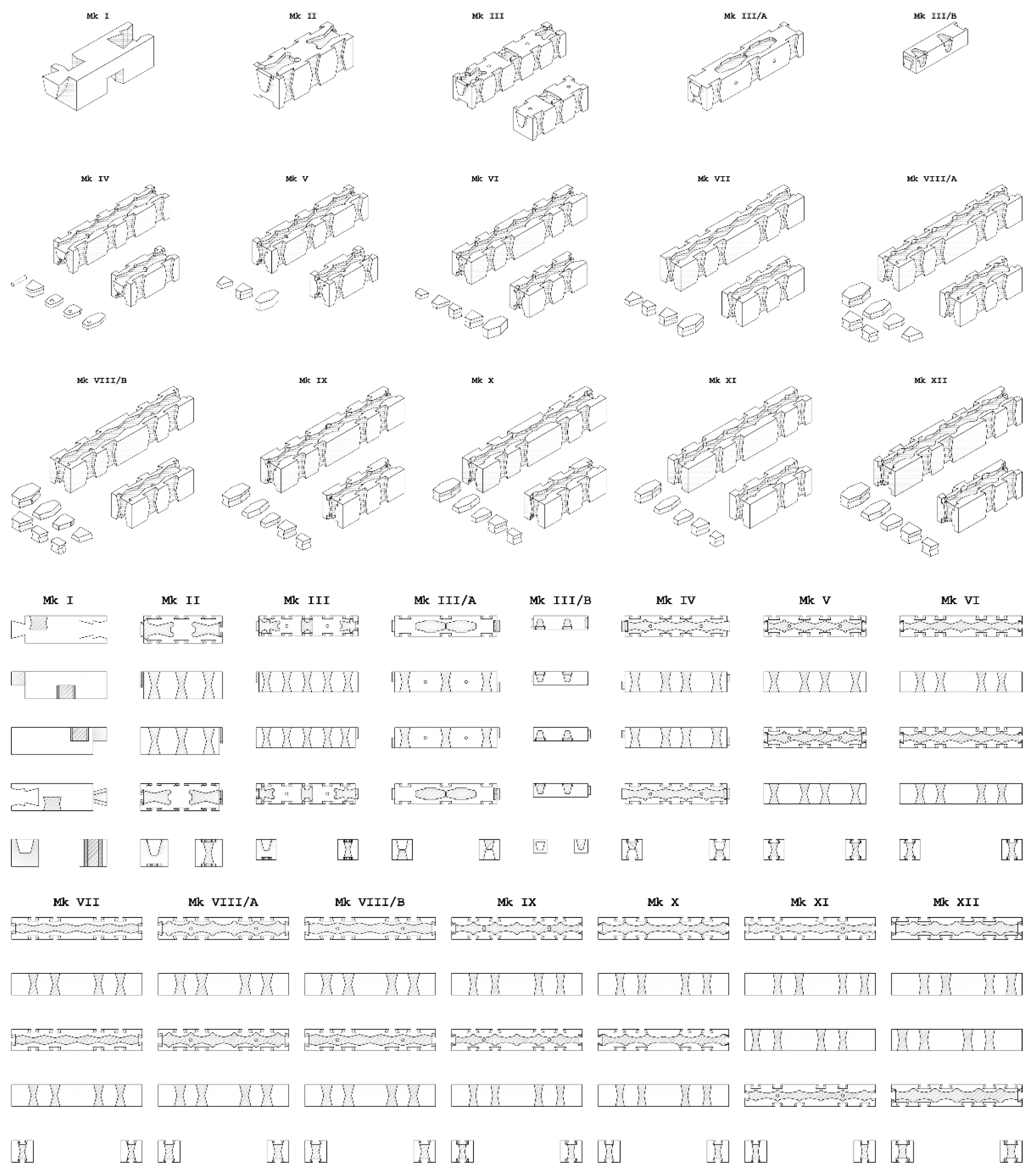
Figure 4.
Axonometric view showing the architectural-scale demonstrator of the LokAlp Mk. XII system. A human figure is included for scale comparison and to contextualize the spatial dimensions of the assembly.
Figure 4.
Axonometric view showing the architectural-scale demonstrator of the LokAlp Mk. XII system. A human figure is included for scale comparison and to contextualize the spatial dimensions of the assembly.
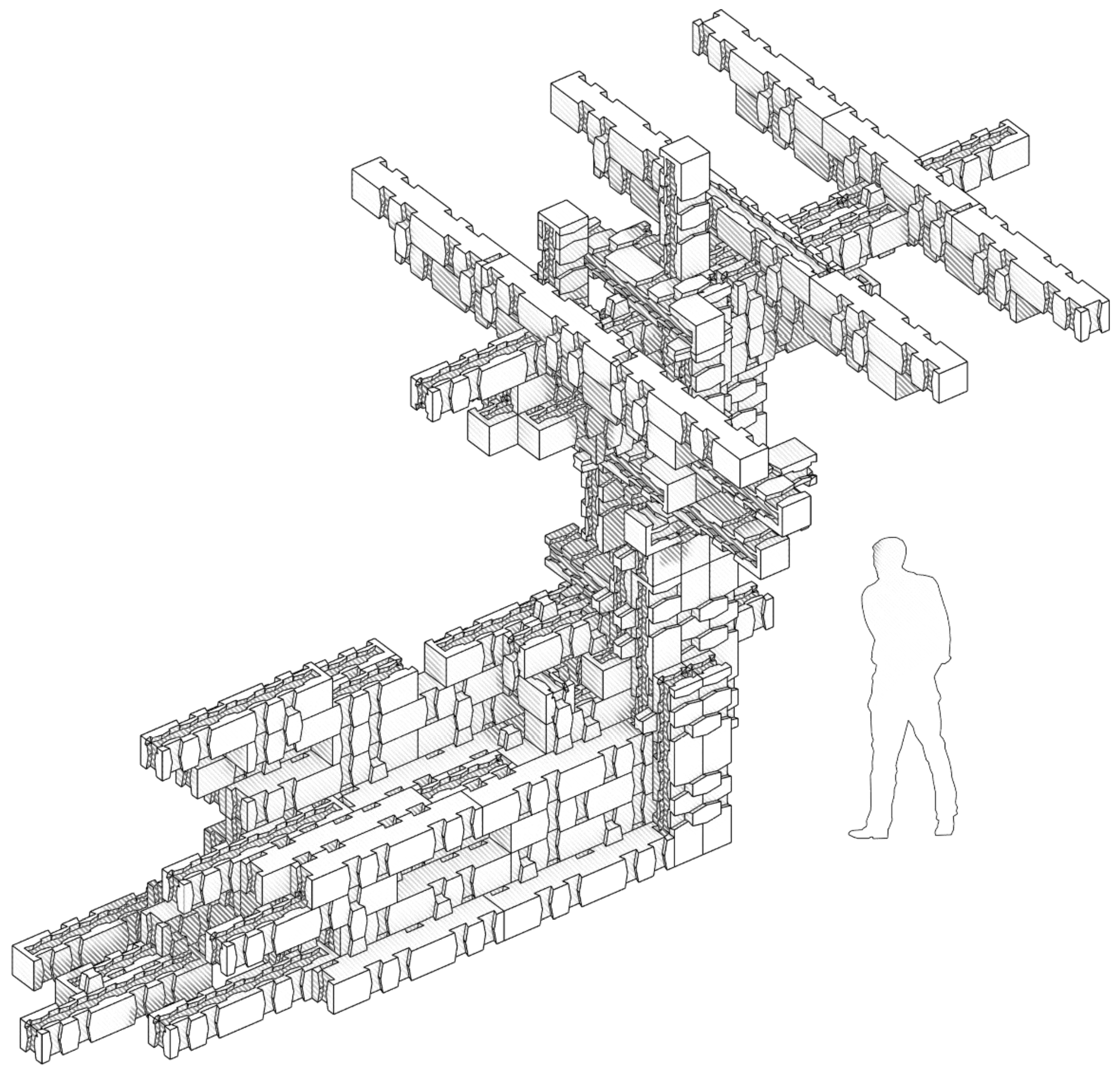
Figure 5.
Photograph of the production facility operated by the project’s industrial partner (top). Below: photographic documentation of the machining process conducted with the Hundegger cutting center, illustrating the execution of dovetail joinery for the production of LokAlp blocks.
Figure 5.
Photograph of the production facility operated by the project’s industrial partner (top). Below: photographic documentation of the machining process conducted with the Hundegger cutting center, illustrating the execution of dovetail joinery for the production of LokAlp blocks.
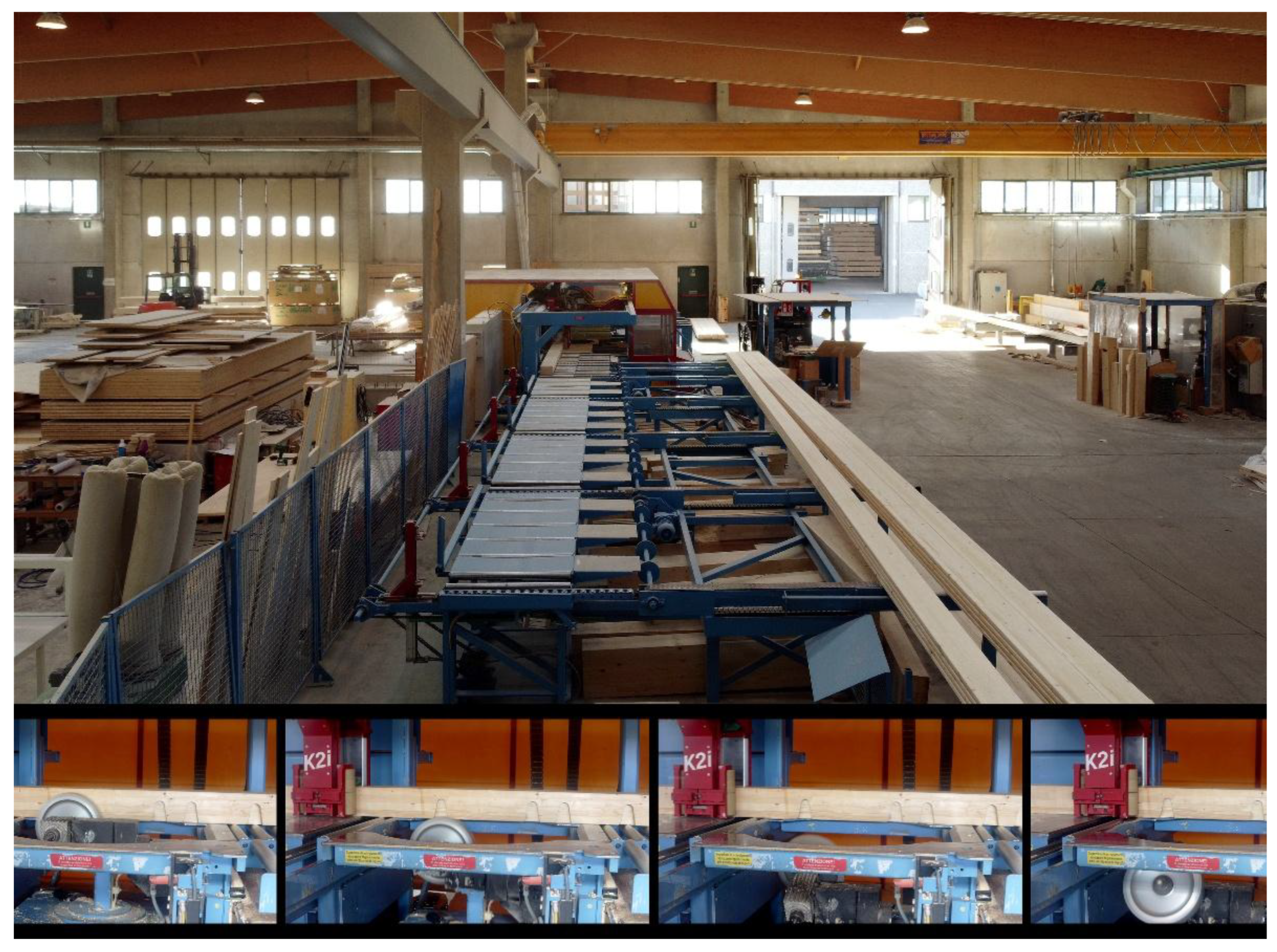
Figure 7.
Completed architectural-scale demonstrator of the LokAlp construction system.
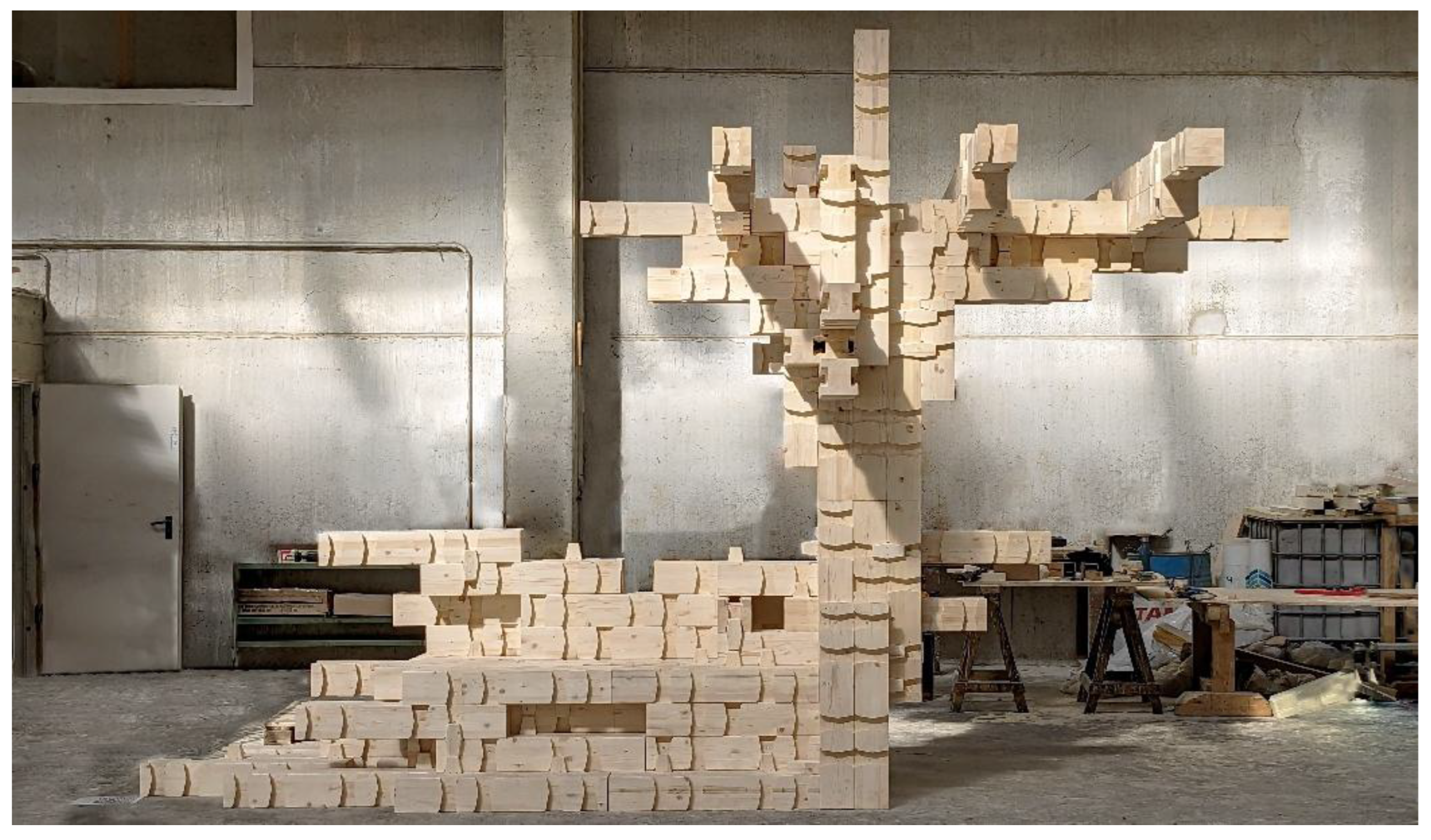
Figure 8.
Assembly process carried out on scaffolding within a self-construction context.
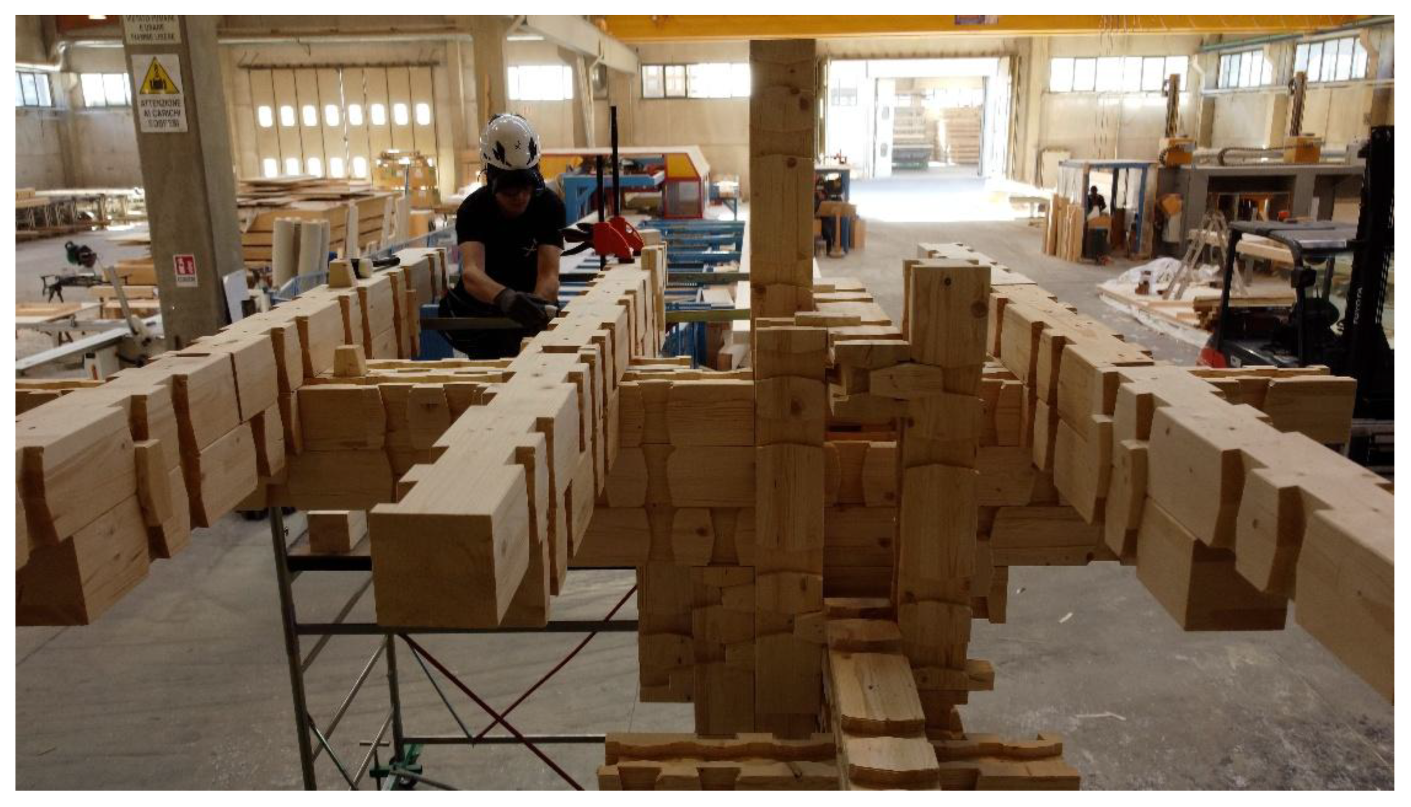
Figure 9.
User interface of smart glasses displaying step-by-step assembly instructions.
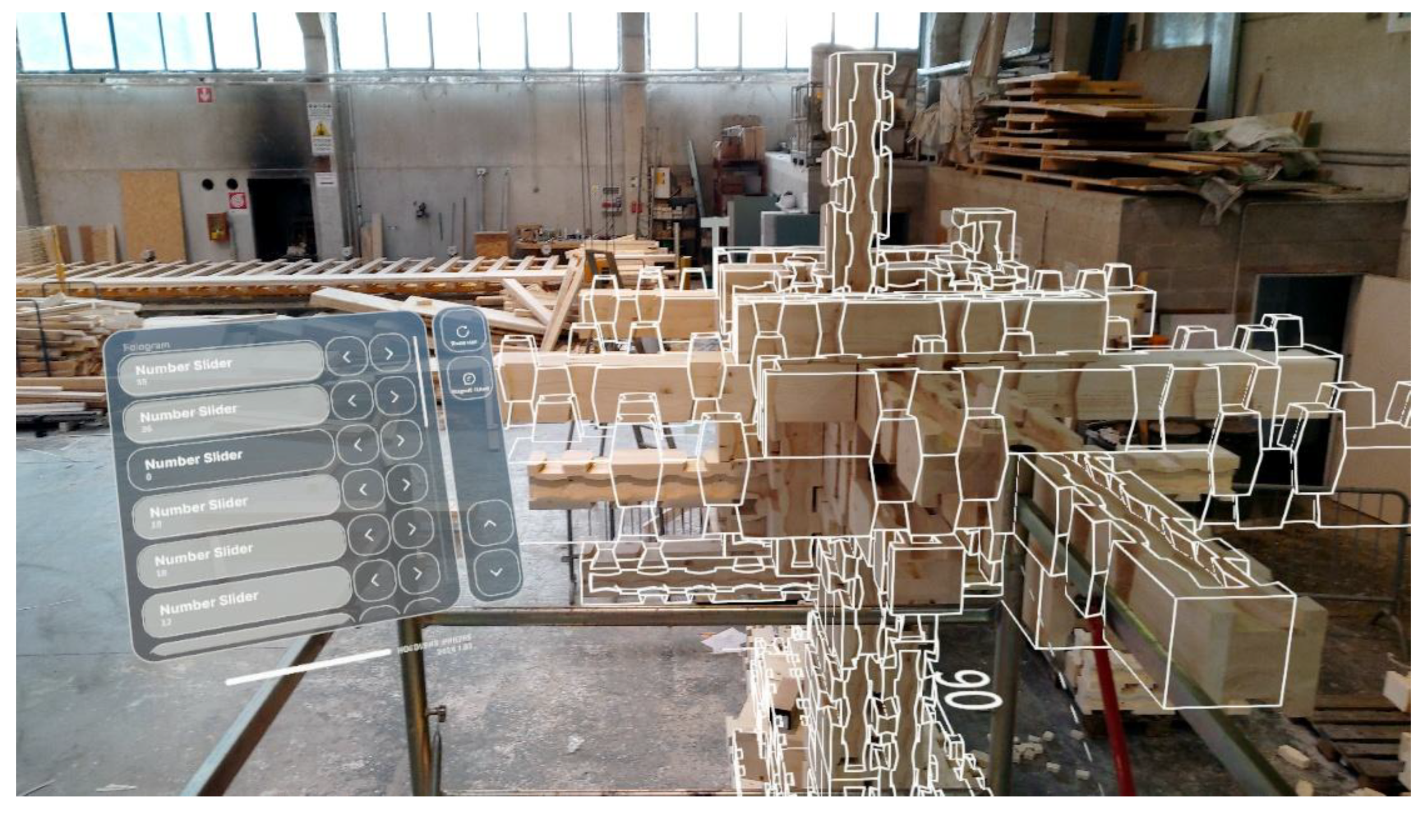
Figure 10.
Axonometric views illustrate the disassembly of the architectural-scale demonstrator and the subsequent reuse of the same LokAlp Mk. XII components for the construction of a standard residential structural module. The new configuration includes vertical supports (pillars), primary and secondary beams, and load-bearing wall elements, demonstrating the system’s adaptability and circularity within conventional building contexts.
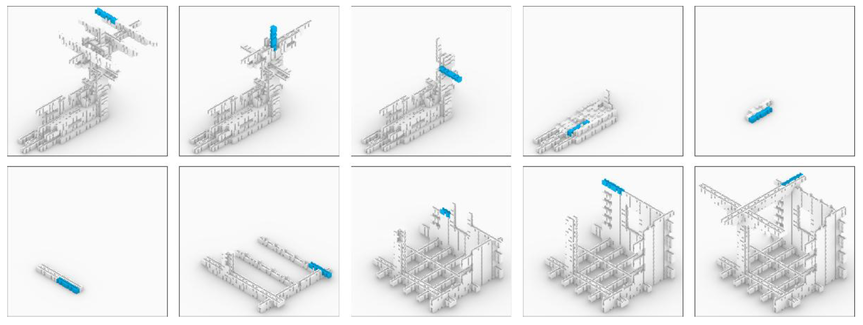

Table 1.
Overview of the 15 LokAlp prototypes. Data refer to the longest structural unit (Figure 1). Dim. 1 and Dim. 2 indicate, respectively, the block’s cross-sectional size and total length. Conf. refers to the total number of configurations per block. Cubic Matrix indicates compliance with a cubic spatial grid. 3-axis knot, Openings, and Angle refer to the ability to form three-way joints, integrate openings (windows/doors), and create orthogonal wall connections without protrusions.
| Model | Dim. 1 [mm] |
Dim. 2 [mm] |
Conf. | Cubic matrix | 3 axis knot | Openings | Angle | Weight [kg] |
Waste [%] |
|---|---|---|---|---|---|---|---|---|---|
| Mk. I | 200 | 600 | 15 | Yes | No | No | Yes | 8.1 | 35.7 |
| Mk. II | 200 | 600 | 23 | Yes | No | No | Yes | 6.8 | 18.6 |
| Mk. III | 200 | 600 | 37 | Yes | No | No | Yes | 6.1 | 16.8 |
| Mk. III/A | 15 | 75 | 22 | Yes | No | No | Yes | 6.3 | 20.5 |
| Mk. III/B | 10 | 40 | 10 | Yes | No | No | Yes | 1.5 | 20.8 |
| Mk. IV | 15 | 75 | 38 | No | No | Yes | Yes | 5.8 | 27.8 |
| Mk. V | 15 | 75 | 40 | No | Yes | Yes | Yes | 5.5 | 28.2 |
| Mk. VI | 15 | 90 | 44 | Yes | No | Yes | No | 6.8 | 25.7 |
| Mk. VII | 16 | 96 | 44 | Yes | Yes | Yes | No | 8.6 | 22.6 |
| Mk. VIII/A | 16 | 96 | 44 | Yes | Yes | Yes | No | 7.7 | 30.1 |
| Mk. VIII/B | 16 | 96 | 44 | Yes | Yes | Yes | No | 7.8 | 29.5 |
| Mk. IX | 16 | 96 | 44 | Yes | Yes | Yes | No | 8.4 | 24.2 |
| Mk. X | 16 | 96 | 40 | No | No | Yes | No | 8.4 | 23.9 |
| Mk. XI | 16 | 96 | 44 | No | No | Yes | Yes | 8.7 | 21.8 |
| Mk. XII | 16 | 96 | 44 | Yes | Yes | Yes | Yes | 7.6 | 30.1 |
Disclaimer/Publisher’s Note: The statements, opinions and data contained in all publications are solely those of the individual author(s) and contributor(s) and not of MDPI and/or the editor(s). MDPI and/or the editor(s) disclaim responsibility for any injury to people or property resulting from any ideas, methods, instructions or products referred to in the content. |
© 2025 by the authors. Licensee MDPI, Basel, Switzerland. This article is an open access article distributed under the terms and conditions of the Creative Commons Attribution (CC BY) license (http://creativecommons.org/licenses/by/4.0/).
Copyright: This open access article is published under a Creative Commons CC BY 4.0 license, which permit the free download, distribution, and reuse, provided that the author and preprint are cited in any reuse.


