
Submitted:
19 May 2025
Posted:
20 May 2025
You are already at the latest version
Abstract
The proposal of this research activity is to produce composite hydrogel-bioactive glass. The primary purpose of this research is to develop and optimize 3D printed scaffolds using doped bioglass, aimed at enhancing bone regeneration in bone defects. The bioglass, a bioactive material known for its bone-bonding ability (SiO2–P2O5–CaO–Na2O), co-doped with europium and silver will be synthesized and doped to improve its biological properties. This doped bioglass will then be combined with a biocompatible hydrogel, chosen for its adequate cellular response and printability. The composite material will be printed to form a scaffold, providing a structure that not only supports the damaged bone, but also encourages osteogenesis. A variety of methods were employed to assess the rheological, compositional, structural, and morphological characteristics of the samples: Fourier Transformed Infrared Spectroscopy (FTIR), Scanning Electron Microscopy (SEM) coupled with Energy-dispersive X-ray Spectroscopy (EDS). Additionally, simulated body fluid (SBF) immersion for bioactivity monitoring, and immunocytochemistry for cell viability were used to evaluate the biological response of the scaffolds.
Keywords:
bioglass
; scaffolds
; 3D printing
; tissue engineering
; hydrogels
; biopolymers
; composite materials
1. Introduction
Bone defects, resulting from traumatic injuries, congenital anomalies, or pathological conditions, pose significant challenges in orthopedic and dental practices due to their high prevalence and complexity [1]. The global burden of bone defects is substantial, with millions of individuals affected annually. For instance, the incidence of traumatic bone defects in the United States alone is estimated to be around 6 million cases per year, with a significant portion attributed to sports injuries, vehicular accidents, and falls [2].
The state of the art in bone defect treatment encompasses various strategies, ranging from conservative approaches to advanced regenerative therapies [3]. The primary objective in treating bone defects is to restore the structural integrity and functional capabilities of the affected bone. Traditional treatments include autografts, allografts, and synthetic bone substitutes [4]. Autografts, which involve the transplantation of bone tissue from a donor site to the defect site, are considered the gold standard [5] in bone defect repair due to their osteogenic, osteoconductive, and osteoinductive properties [6]. However, their application is limited by the availability of donor sites, donor site morbidity, and the risk of disease transmission. Allografts, which use bone tissue from a genetically non-identical member of the same species, offer an alternative to autografts but are associated with a higher risk of immune rejection and disease transmission [4].
In recent years, the field of tissue engineering has emerged as a promising avenue for the treatment of bone defects [7]. Scaffolds, typically made from biodegradable polymers, ceramics, or composites, provide a temporary structure that guides bone tissue regeneration [8]. The choice of scaffold material is critical, as it must possess suitable mechanical properties [9], porosity, and bioactivity to support cell attachment, proliferation, and differentiation [10]. The integration of biomaterials, cells, and growth factors in tissue engineering has led to the development of advanced bone graft substitutes that closely mimic the structure and function of natural bone [4]. These bioengineered bone grafts have shown promising results in preclinical and clinical studies, demonstrating their potential to enhance bone regeneration and accelerate the healing process in various bone defect models [11].
Despite the progress made in the field of bone defect treatment, challenges remain, particularly in the areas of personalized medicine [12], the optimization of scaffold design and fabrication techniques [13], and the development of predictive models for patient-specific treatment strategies. Emerging technologies, such as 3D printing [14] and nanotechnology [15], offer new opportunities for the design and fabrication of patient-specific bone graft substitutes that can precisely match the structural and mechanical properties of the native bone tissue [16].
Additive manufacturing, also mainly known as 3D printing [17], is a technique that involves the deposition of successive layers of material on a build bed, resulting in the creation of objects with intricate geometries [18]. In the medical field, tangible models created by additive manufacturing are used to evaluate complex anatomies [19]. Furthermore, the technique can be used to fabricate patient-specific constructs like drill guides, saw guides, and medical implants, which can reduce operating times and enhance the accuracy of surgical procedures [20].
3D Bioprinting, a subset of additive manufacturing, as defined by Groll et al. [21], is the process of using computer-assisted transfer to pattern and assemble biological materials, including molecules, cells, tissues, and biodegradable biomaterials, combined in a bioink, [22] based on pre-generated perimeters, resulting in the formation of an biofunctional assembly [13]. Klebe demonstrated one of the first models using 3D bioprinting technology in 1988, using a computer-controlled inkjet printer or graphic plotter, described as "cytoscribing" [23], being used to precisely position cells on a 2D substrate [24]. 3D bioprinting offers numerous advantages considered revolutionary in biomedical engineering. This can automate the layer-by-layer fabrication of cell-laden structures, both in vitro and in vivo [25].
Extrusion-based bioprinting (EBB) has emerged as a popular bioprinting technique, enabling the creation of complex 3D structures with high precision and reproducibility [6]. Fluid dispensing is achieved using mechanical or pneumatic actuation, where the bioink is pushed through a nozzle. The normal force exerted by the downward motion of the plunger induces a rheological response from the bioink, which determines its flow through the nozzle [26]. The flow response of a bioink is vital while developing and screening bioinks [3].
Careful selection of the initial bioink impacts how the construct can be printed, the final cell viability [27], and mechanical properties of the final device [28]. Amongst all contributing factors, rheological properties (shear-thinning, quick shear recovery, adjustable viscosity, pseudoplasticity, thixotropy, substantial yield stress, relatively high viscosity, viscoelastic properties) [29] and printing parameters (printability, printing fidelity, shape retention, long-term shape fidelity, formability) [30] are primary factors that influence the quality of bioprinted constructs. The printing parameters mentioned above have a great influence on geometric accuracy and cell viability, determining the success of the bioprinting [28].
Current research focuses on developing biomaterials with favorable biological characteristics, including biocompatibility, non-toxicity, facilitation of cell migration, proliferation, differentiation, and tissue formation [7]. These properties are crucial for the successful application of bioinks in regenerative medicine and tissue engineering (Fig. 1.1.), ensuring safe, effective constructs that support cell growth and differentiation into functional tissues [31].
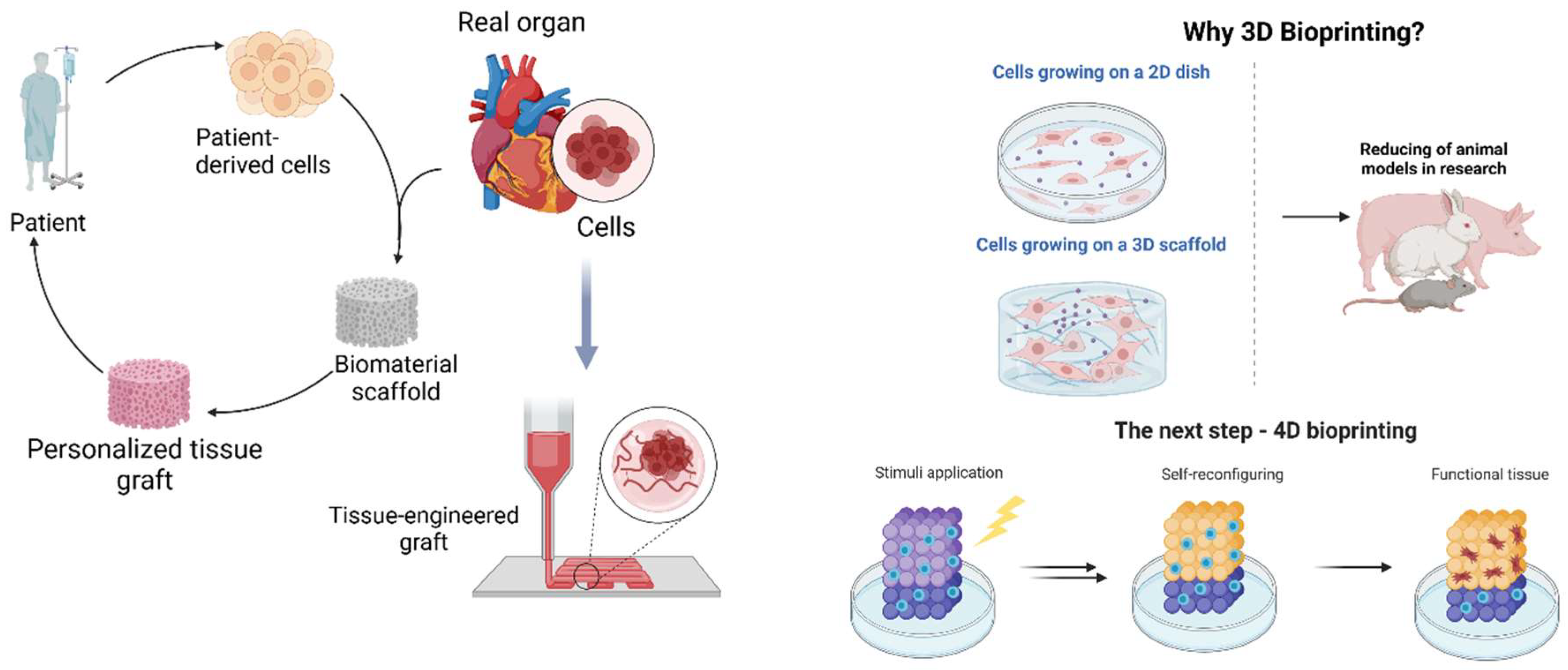
Figure 1. 1.
3D Bioprinting applications and future perspectives (created with Biorender).
A class of hydrogels, polymeric networks that possess the ability to absorb significant amounts of water or biological fluids [8], with high potential in the biomedical field is based on natural biopolymers [32]. This characteristic arises from the chemical interactions between the polymer chains that constitute the hydrogel, often containing hydrophilic functional groups such as hydroxyl, carboxyl, and amine groups, which attract and bind water molecules through hydrogen bonding and other intermolecular forces [33]. These lightweight mesoporous materials with tunable surface and volume properties offer a unique combination of mechanical strength and 3D surface topography [3].
Regarding biopolymers used in tissue engineering, alginate is a linear polysaccharide composed of 1,4-β-D-mannuronic acid (M) and α-L-guluronic acid (G) blocks [34]. The M-block segments are flexible, while the G-block segments confer rigidity, alginate's viscoelasticity depending on the frequency of these blocks. When exposed to calcium ions (Ca2+), alginate forms a three-dimensional network through ionic bonding, known as the "egg box" model [35]. This crosslinking mechanism enhances mechanical strength and stability, making alginate valuable for tissue engineering, drug delivery, and food products [36].
In addition to polysaccharides, gelatin is a water-soluble protein derived from collagen hydrolysis, composed of polypeptide chains with amino acids like glycine, proline, hydroxyproline, and arginine [37]. Its amphoteric nature, due to amine and carboxyl groups, allows for gel formation and interaction with other molecules, creating integrin-binding situses for enhanced cell adhesion [38].
When it comes to oxidic osteogenic materials, the bioresorbable 4S5S bioglass (SiO2–P2O5–CaO–Na2O) [39] can be tailored to include various dopants to impart specific properties. The bioglass (BG) doped with silver and europium [40] imparts potent antibacterial properties, as silver ions can disrupt bacterial cell membranes, inhibit DNA replication, and suppress bacterial respiratory chains, leading to effective control of bacterial growth [41]. This is particularly beneficial in preventing post-surgical infections, a common complication in bone implant procedures [42]. As a result, validating data on the antimicrobial effect of the Eu and Ag doped bioglass against S. aureus, and E. coli, has already been published [40]. On the other hand, Europium doping is described to induce cell differentiation in mesenchymal stem cells and photoluminescent properties [43]. Upon excitation with ultraviolet light, europium emits visible light, allowing for the use of these bioglass compositions in imaging applications [42]. This feature enables non-invasive monitoring of bioglass integration with the host bone tissue, providing valuable insights into the progress of bone regeneration [44].
2. Materials and Methods
2.1. Materials
Tetraethyl orthosilicate (TEOS, Si(OC2H5)4), triethyl phosphate (TEP, (C2H5)3PO4), calcium nitrate tetrahydrate (Ca(NO3)2•4H2O), europium (III) nitrate pentahydrate (Eu (NO3)3•5H2O), sodium alginate, calcium chloride (CaCl2), sodium bicarbonate (NaHCO3), potassium chloride (KCl), magnesium chloride hexahydrate (MgCl2 • H2O), sodium sulfate (Na2SO4), chlorohydric acid (HCl) and ethanol were purchased from Sigma – Aldrich (St. Louis, USA). Sodium nitrite (NaNO2, purity ≥99%), silver nitrate (AgNO3) were procured from Riedel-de Haёn (Honeywell, New Jersey, USA), and the nitric acid (HNO₃) was bought from Fluka™ (Honeywell, New Jersey, USA), while gelatin from porcine skin was bought from Merck (New Jersey, USA).
2.2. Hydrogel Synthesis
The chemical composition of the Eu and Ag doped BG is presented in Table 2.1, while the sol-gel synthesis route employed, and post-processing steps are detailed in a previous work [40].

Table 2.1.
Bioglass composition expressed in molar percentages.
| Bioglass composition (mol%). | |||||
| 65.0 | 4.5 | 2.5 | 24.0 | 1.0 | 3.0 |
| SiO2 | P2O5 | Na2O | CaO | Ag2O | Eu2O3 |
Regarding the hydrogel matrix, the optimal proportions of alginate and gelatin for 3D printing was determined by testing multiple composition with varying concentrations of alginate and gelatin. The compositions were tested for printability, viscosity, and shape stability using a Cellink INKREDIBLE+ 3D bioprinter (Fig. 2.1.). The optimal compositions to be tested consisted of 7% alginate, 8% gelatin, respectively 3% alginate, 7% gelatin, which exhibited good printability, viscosity, and shape stability.
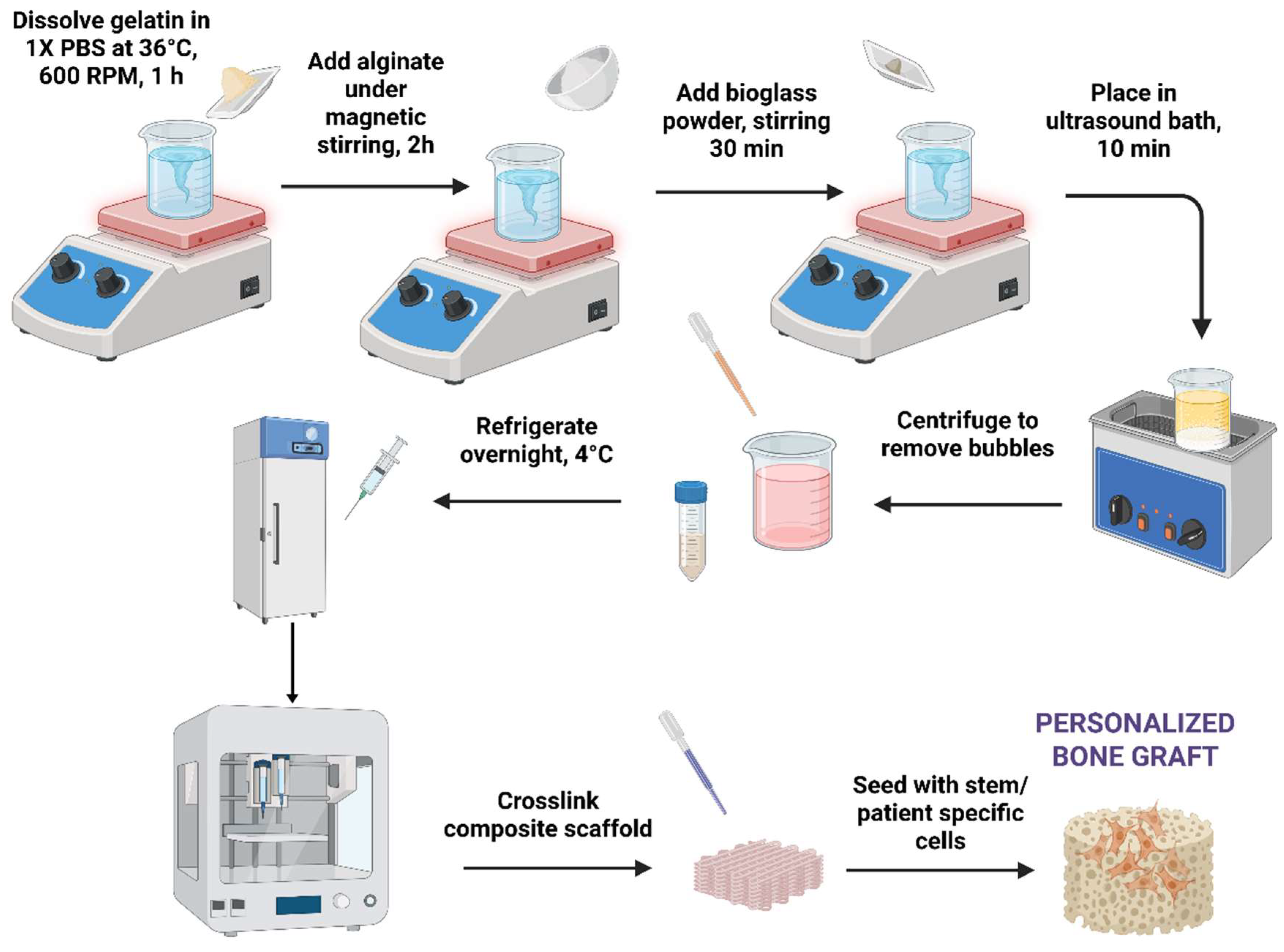
Figure 2. 1.
Composite bioglass-hydrogel material synthesis and printing steps.
To prepare the hydrogel, PBS 1X was placed in a Berzelius flask with a magnetic stirrer on a heated plate (DIAB MS-H280-Pro) at 600 rpm and 36°C to prevent gelatin denaturation. The desired amount of precursors was added, including sodium alginate (Sigma-Aldrich, CAS-No. 9005- 38-3) and gelatin (Gelatin from porcine skin, CAS-No. 9000-70-8, Sigma-Aldrich). Once the gelatin was completely dissolved, the alginate was added, and the mixture was stirred for an additional 2-3 h to ensure complete incorporation.
The inorganic phase entailed the introduction of small amounts of Eu-doped bioglass powder, as seen in Table 2.2. Prior to addition, the bioglass powder was passed through a standard laboratory sieve (mesh size 0.45 μm) to ensure a uniform particulate size. The sieved powder was then added to the organic solution under continuous magnetic stirring. To achieve thorough dispersion of the bioglass particles within the hydrogel matrix, the mixture was subjected to ultrasonication. An ultrasonic bath (Elmasonic S30H, Elma Schmidbauer GmbH, Germany) was employed, where the solution underwent three cycles of ultrasound treatment, each lasting for 10 min.
Table 2. 2.
Hydrogel composition and 3D printing parameters.
|
Sample |
Hydrogel composition |
pH |
Pressure (kPa) |
Nozzle diameter |
Printing speed | Layers | Crosslinking time | ||
| Alginate | Gelatin |
Eu-doped BG |
|||||||
| P1 | 3% | 7% | 8 | 25 | 22 G | 20 mm/s | 4 | 5 min | |
| P2 | 7% | 8% | 7 | 135 | |||||
| P3 | 3% | 6% | 0.25% | 8 | 170 | ||||
| P4 | 7% | 8% | 0.50% | 8 | 210 | ||||
| P5 | 7% | 8% | 0.25% | 8 | 225 | ||||
Upon completion of the ultrasonication process, the homogenized hydrogel precursor solution was transferred to the barrel of a bioprinter syringe. To remove entrapped air bubbles and ensure homogenous hydrogel density, the syringe was manually centrifuged using a 3D printed manual centrifuge. The resulting degassed hydrogel was then stored at 4°C to facilitate gelation. The gelation process was allowed to proceed overnight to yield a fully structured hydrogel suitable for subsequent bioprinting applications.
2.3. 3D printing Process
The biomaterials were printed using an INKREDIBLE+ extrusion-based 3D bioprinter from CELLINK, through a 22 G conical nozzle, 10 × 10 mm square grid-shaped scaffolds were obtained in 90 mm Petri dishes. In order to generate GCode information, Bioscaffolds V2.0 software (Fig. 2.2.) was used. The optimal printing parameters for the obtained compositions are described in Table 2.2.
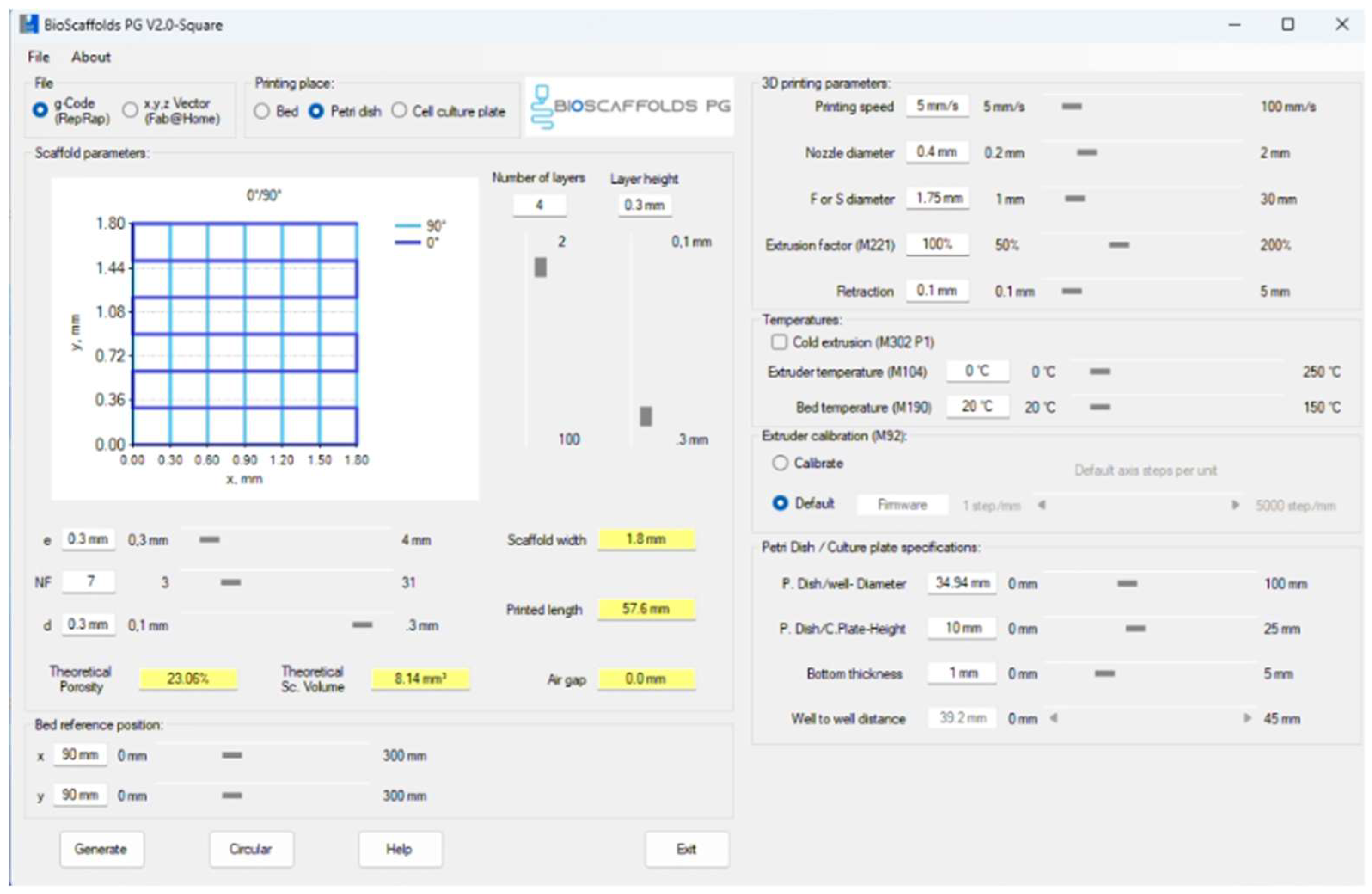
Figure 2. 2.
3D printing parameters settings and GCode generation through Bioscaffolds V2 interface.
Figure 2. 2.
3D printing parameters settings and GCode generation through Bioscaffolds V2 interface.
2.4. Characterization Methods
2.4.1. Rheological Evaluation
The rheological properties of were analyzed to evaluate its suitability for bioprinting applications in an extrusion-based system.
Rheological measurements were obtained using an Anton Paar rheometer with a 25 mm diameter parallel plate geometry. Hydrogel samples, consisting of 6% alginate and 3% gelatin were loaded onto the bottom plate of the rheometer with a 0.5 mm gap. In addition, tests were done also on the composite samples, with negligible differences. The bottom plate temperature was then increased to 25 °C, and the samples were subjected to various measurement profiles. Viscosity and shear stress as a function of shear rate was measured, with a shear rate set to 1–50 s−1 with point durations from 3 to 20 s. The shear stress vs. shear rate graphs were used to determine the dynamic yield stress by fitting the Herschel-Buckley model to the data with the following equation:
where σ is shear stress, γ is shear rate, K is the consistency coefficient, n is the flow behavior index, and σo is the dynamic yield stress.
𝜎=𝐾𝛾𝑛+𝜎𝑜
2.4.2. Scanning Electron Microscopy and Energy Dispersive X-Ray Spectroscopy
Scanning electron microscopy (SEM) is viewed as a non-invasive method for examining the morphological characteristics of materials. These examinations were conducted using the FEI Inspect F50 SEM equipped with an energy dispersive X-ray spectrometer (EDS), which enables the analysis of the elemental composition of the samples. Given that each element has a unique energy spectrum, this technique allows for the identification of the constituent elements. Additionally, the intensity of the spectral peaks provides insights into the relative abundance of these elements within the sample.
Prior to analysis, the samples are prepared by coating them with a thin layer of gold to enhance their conductivity, applied through a process called DC magnetron sputtering.
2.4.3. Fourier Transformed Infrared Spectroscopy
Fourier transform infrared spectroscopy (FTIR) is a technique commonly used for the physicochemical characterization of organic materials. Each absorption band corresponds to a mode of vibration of a chemical bond between two atoms, and if a chemical bond is characteristic of a constituent, it can be considered a tracer of that constituent.
Measurements were separately on the bioglass dried gel and synthesized powder, using the FTIR Jasco spectrometer, at room temperature using the attenuated total reflection (ATR) module, with 32 scans of the samples between 4000 and 500 cm-1 at a resolution of 4 cm-1. Samples were dried and then placed on the attenuated total reflection accessory of the spectrometer. In addition, FTIR spectra were achieved for the bioglass powder during previous experiments and their results are presented in our previous work [40].
2.4.4. Optical Microscopy – Printing Accuracy
The assessment of the printing accuracy for the 3D printed scaffolds was carried out using optical microscopy, as seen in Fig. 2.3. Furthermore, to quantitatively assess the precision of the printing process, the strand thickness of the gel within the scaffolds was analyzed by comparing the measured strand dimensions with the nozzle diameter. Utilizing ImageJ software, the strand thickness was measured with its built-in Analysis function.
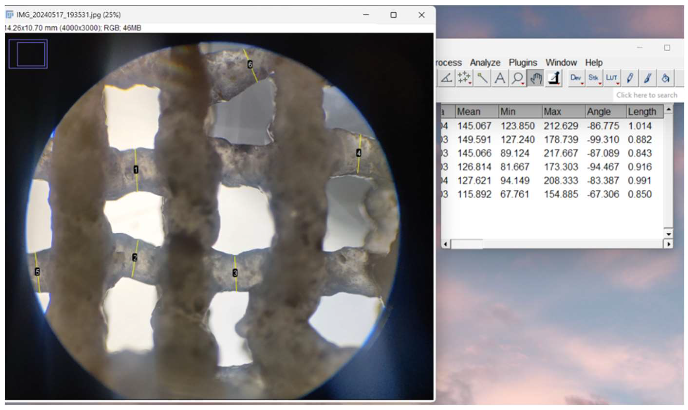
Figure 2. 3.
Printability evaluation using strand measurement through ImageJ software.
2.4.5. Swelling Degree
The swelling behavior of the scaffolds was determined using the gravimetric method. The scaffolds were initially weighed in a dry state and then submerged in 1X PBS solution. After a 4 h period, ensuring complete absorption of PBS, the scaffolds were weighed again. The swelling capacity of the gel was quantified using the following equation:
where Wwet represents the weight of the scaffold after immersion in PBS and Wdry represents the weight of the scaffold before being submerged [10].
2.4.6. Degradation Rate
To evaluate the degradation profile, both pristine scaffolds (gelatin and alginate) and composite scaffolds incorporating bioglass were immersed in 3 mL of PBS 1X at 37.1 °C. The scaffolds were weighed at regular intervals: on the first, third, seventh, fourteenth, and twenty-eighth days, to monitor the degradation process over time.
2.4.7. Porosity Evaluation
The porosity of the 3D printed scaffolds was evaluated using the ImageJ software, as illustrated in Fig. 2.4. First, the digital images of the scaffolds were subjected to the Threshold function, which allowed for the segmentation of the scaffold solid and void regions by setting a specific contrast range. This step enabled the distinction between the polymer matrix and the pore spaces, converting the grayscale image into a binary format.
Subsequently, the Particle Analyzer tool was employed to quantify the porosity parameters. This feature of ImageJ analyzed the binary image, counting and measuring the individual pore areas, as well as their distribution within the scaffold.
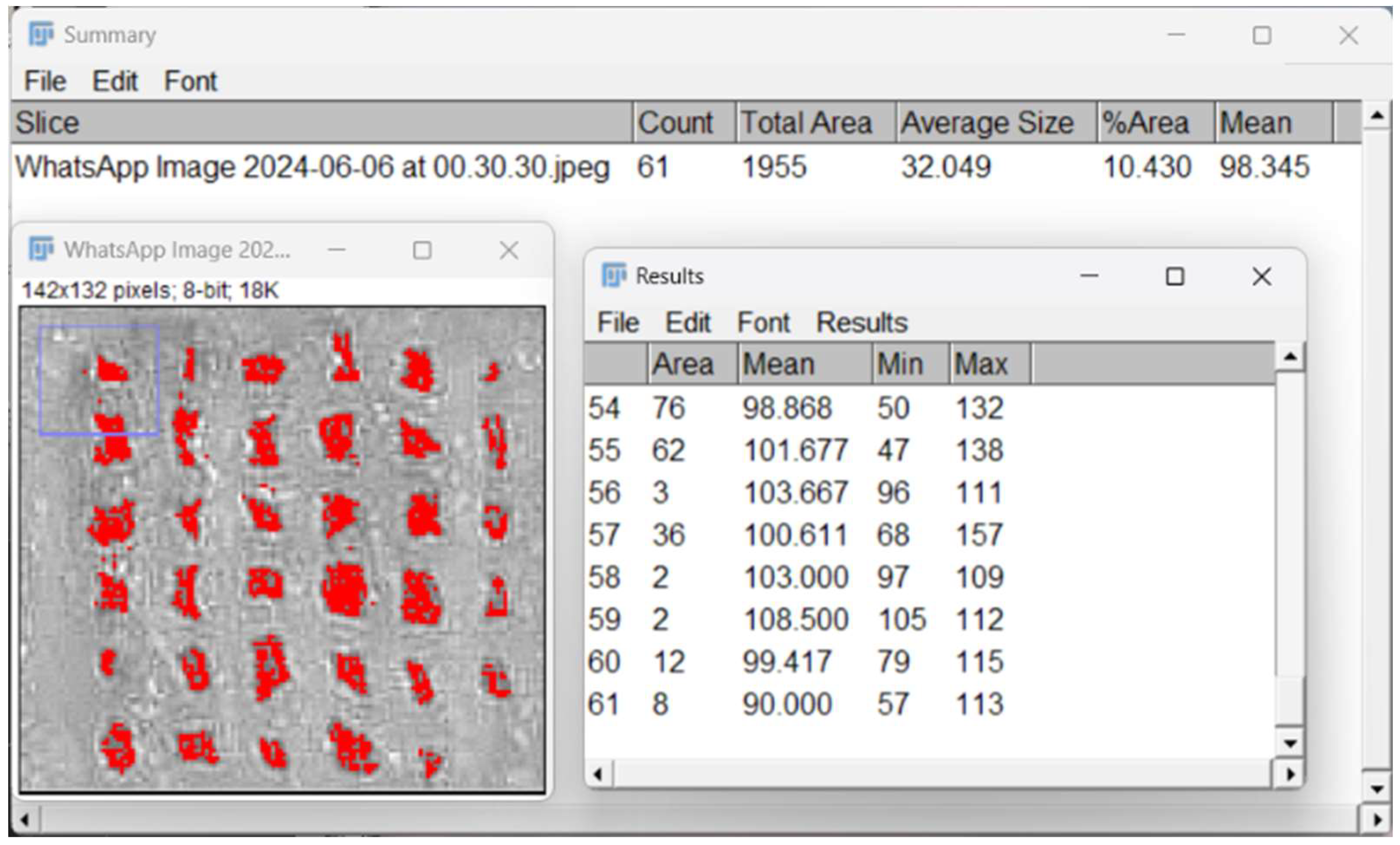
Figure 2. 4.
Porosity evaluation through ImageJ software.
2.4.8. In Vitro Mineralization
The methodology for assessing the biological activity of doped bioglass thin films involved several key procedures. Initially, a simulated body fluid (SBF) was prepared using the method outlined by Kokubo et al. [45]. Following this, the sample, weighing 30 mg, was carefully measured, and placed into a sterile vessel. The sample was then completely submerged by adding 1.5 mL of the SBF solution that had been prepared. The submerged sample was then subjected to an incubation period at 37 °C for a duration of 28 days. Upon completion of this immersion phase, the sample was carefully removed from the SBF solution and meticulously rinsed with deionized water. Finally, the sample underwent analysis using scanning electron microscopy (SEM) to evaluate its biological response.
To assess in vitro mineralization and apatite formation, the composite scaffolds were placed in a 12-well plate and submerged in 3 ml of 1.5X SBF, prepared according to the protocol outlined by Kokubo et al [45] (Table 2.3.). The samples were then incubated in a heated incubator at 37.1 °C. After a duration of 14 days, the samples were examined under an optical microscope for analysis.
Table 2. 3.
Composition of SBF 1.5X.
| Order | Reagent | Quantities for 100 ml SBF 1.5X |
| #0 | Ultra-pure water | 75 mL |
| #1 | NaCl | 1.1994 g |
| #2 | NaHCO3 | 0.0525 g |
| #3 | KCl | 0.0336 g |
| #4 | K2HPO4・3H2O | 0.0342 g |
| #5 | MgCl2・6H2O | 0.0458 g |
| #6 | 1 kmol/m3 HCl | 6 cm3 |
| #7 | CaCl2 | 0.0417 g |
| #8 | Na2SO4 | 0.0107 g |
| #9 | (CH2OH)3CNH2 | 0.9086 g |
| #10 | 1 kmol/m3 HCl | Appropriate amount for adjusting pH |
2.4.7. Cell Seeding and LIVE/DEAD Assay
Human fetal osteoblastic cells (hFOB 1.19) were cultured in a humidified chamber (95% air; 5% CO2) at 37 °C in Dulbecco’s Modified Eagle’s Medium (DMEM) and supplemented with 10% fetal calf serum and 1% penicillin–streptomycin. Once in confluence, cells were trypsinized and counted. The scaffolds were sterilized via UV-C for 20 min on each side and immersed in cell medium. On top of each scaffold, 2 × 10⁵ cells were seeded with 2000 μL of DMEM in each well and were incubated at 37 °C for 48 h. For the LIVE/DEAD cell viability test, the manufacturer (Invitrogen) protocol was followed [46].
The growth medium was removed from the scaffold samples, and they were gently rinsed with phosphate-buffered saline (PBS) to eliminate any detached cells or debris. A fresh staining solution was prepared by combining equal volumes of the diluted Calcein AM and Propidium Iodine solutions. The LIVE/DEAD staining solution was added to each sample, and they were incubated at room temperature in the dark for 30-60 min to facilitate the penetration of the dyes into the cells and their binding to the respective intracellular targets [46].
Following incubation, the samples were rinsed with PBS to remove any unbound stain. The samples were examined using a fluorescence microscope (Zeiss LSM) equipped with filters suitable for detecting green and red fluorescence. Image analysis software, ZEN Studio, was utilized to quantify the number of live (green) and dead (red) cells. The fluorescence intensity was measured, or the cells in each color channel were manually counted, and the viability percentage was calculated using the formula:
Viability Percentage = (Number of Live Cells / Total Number of Cells) × 100
3. Results
3.1. 3D Printing Process
The 10×10 mm, 4-layered porous scaffolds were obtained using EBB 3D printing technology. Figure 3.1. display their shape stability, their design integrity being maintained over time, at room temperature. The printability of these scaffolds was demonstrated by the lack of gaps or air bubbles in the filament strands.
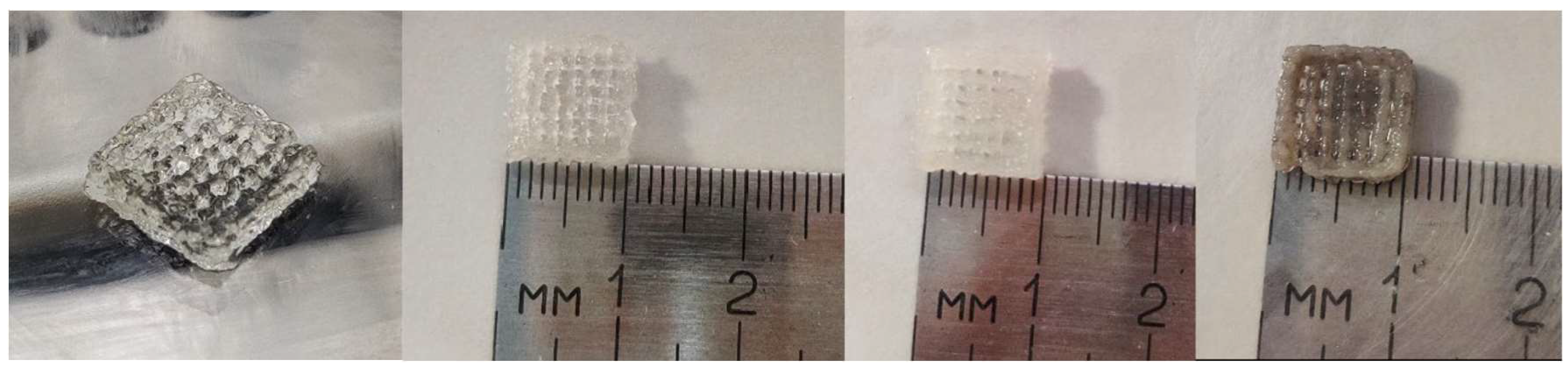
Figure 3. 1.
Morphology, shape, and measurements of 3D printed scaffolds P2-P5.
The composite structure of the scaffolds was achieved, and the porosity was controlled to facilitate cell adhesion, proliferation, and the penetration of cells and extracellular matrix essential for tissue regeneration.
3.2. Characterization Methods
3.2.1. Rheological Evaluation
Viscosity and shear stress were plotted against shear rate in log-log, as illustrated in Fig. 3.2. revealing a pronounced shear-thinning behavior, as evidenced by the rapid decrease in viscosity with increasing shear rate. In the context of extrusion based bioprinting, the material viscosity and its shear thinning properties will determine how easily it will flow through the printer’s nozzle.
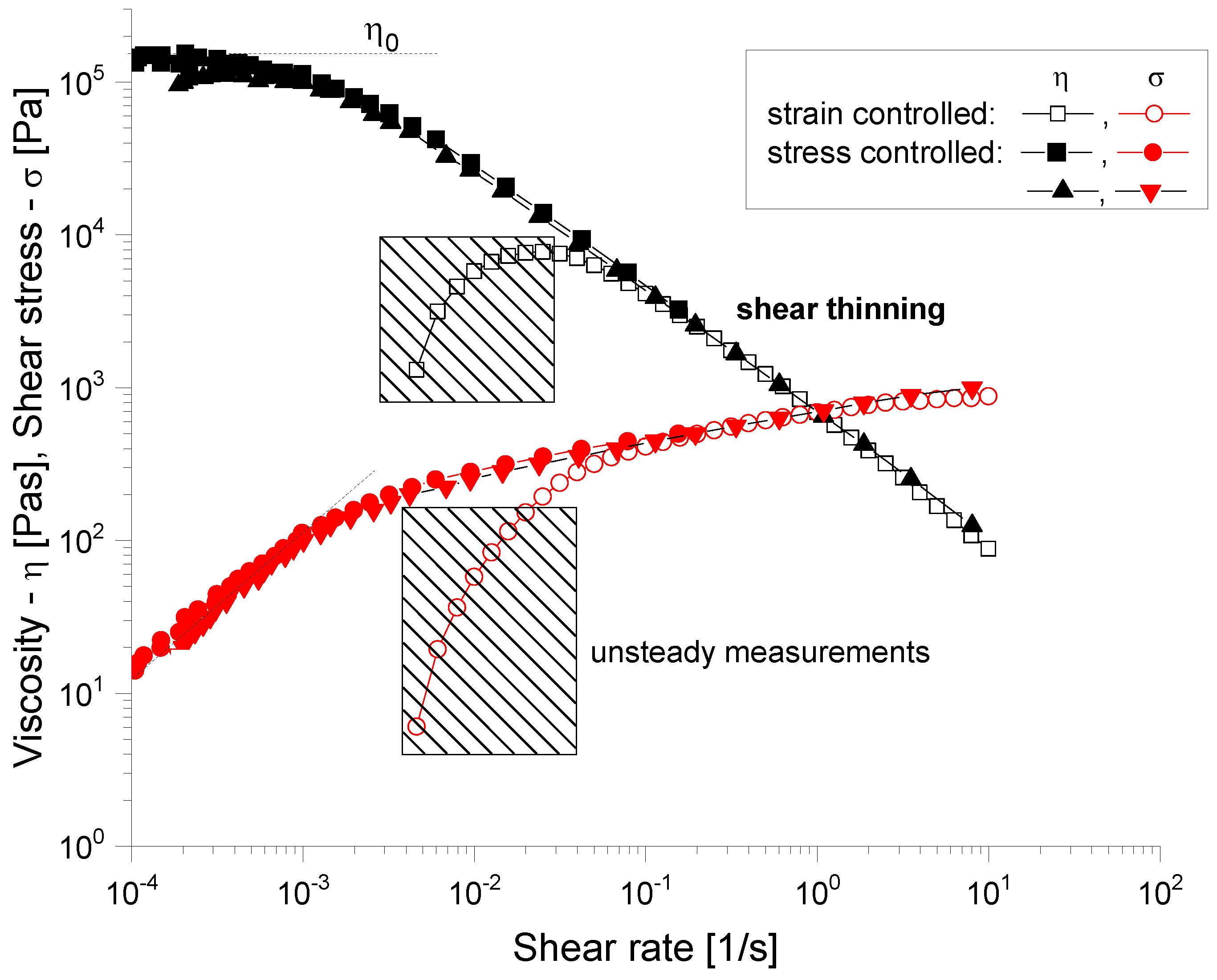
Figure 3. 2.
Rheological characterization of uncrosslinked hydrogels. Viscosity as a function of shear rate, from 1 to 50 s−1 (black). Shear stress as a function of shear rate, from 1 to 50 s−1 (red).
Figure 3. 2.
Rheological characterization of uncrosslinked hydrogels. Viscosity as a function of shear rate, from 1 to 50 s−1 (black). Shear stress as a function of shear rate, from 1 to 50 s−1 (red).
3.2.2. Scanning Electron Microscopy and Energy Dispersive X-Ray Spectroscopy
The scanning electron microscopy (SEM) images in Fig. 3.3. provide a comprehensive view of the microstructural characteristics of the composite scaffolds. The P3 sample, composed of 3%Alg-6%Gel-0.25%BG, exhibits a well-defined porous interconnected structure with relatively smooth surface texture punctuated by small nodular features. The bioglass particles appear to be successfully integrated in the polymer matrix during the fabrication process.
When examining the P4 formulation (7%Alg-8%Gel-0.25%BG), the increased polymer concentration manifests in a more pronounced porous network with added bioglass agglomerates well-embedded within the polymeric structure. This enhanced structural definition can be attributed to the higher concentration of both alginate and gelatin components, which contribute to a more robust scaffold architecture.
The P5 sample (7%Alg-8%Gel-0.5%BG), containing the highest bioglass concentration, demonstrates notably different surface characteristics. The increased bioglass content results in a rougher surface topology with more pronounced surface irregularities. The pore structure appears less uniform compared to P3 and P4, and there is evidence of increased particle aggregation, likely due to the higher concentration of bioglass particles in the composite. This increase in porosity and surface roughness is a direct result of the incorporation of bioglass particles into the hydrogel matrices.
The EDS analysis provides valuable insights into the elemental composition of the scaffolds. In sample P3, strong peaks for phosphorus (P) and calcium (Ca) indicate the presence of calcium phosphate phases, while the silicon (Si) peak confirms successful incorporation of bioglass. The presence of sodium (Na) and oxygen (O) can be attributed to the alginate structure, and trace elements such as silver (Ag) and europium (Eu) are also detected. The P4 sample shows similar elemental constituents but with notably different peak intensities, particularly showing dominant phosphorus and silicon signals with reduced calcium intensity compared to P3. This variation in elemental distribution suggests that the different polymer and bioglass concentrations influence not only the physical structure but also the chemical composition of the resulting scaffolds. Finally, the presence of gold is a result of the deposited layer intended to ensure the sample conductivity [40].
A comparative analysis of the SEM and EDS results reveals significant changes in both the structural and compositional properties of the scaffolds upon the introduction of bioglass. The increased porosity and surface roughness observed in the SEM images of the composite scaffolds are likely to enhance their mechanical properties and surface area, which are crucial factors for cell adhesion, proliferation, and tissue regeneration. Furthermore, the presence of bioglass, as evidenced by the EDS data, introduces bioactive elements such as silicon and calcium that can promote osteogenic activity and improve the overall biological performance of the scaffolds.
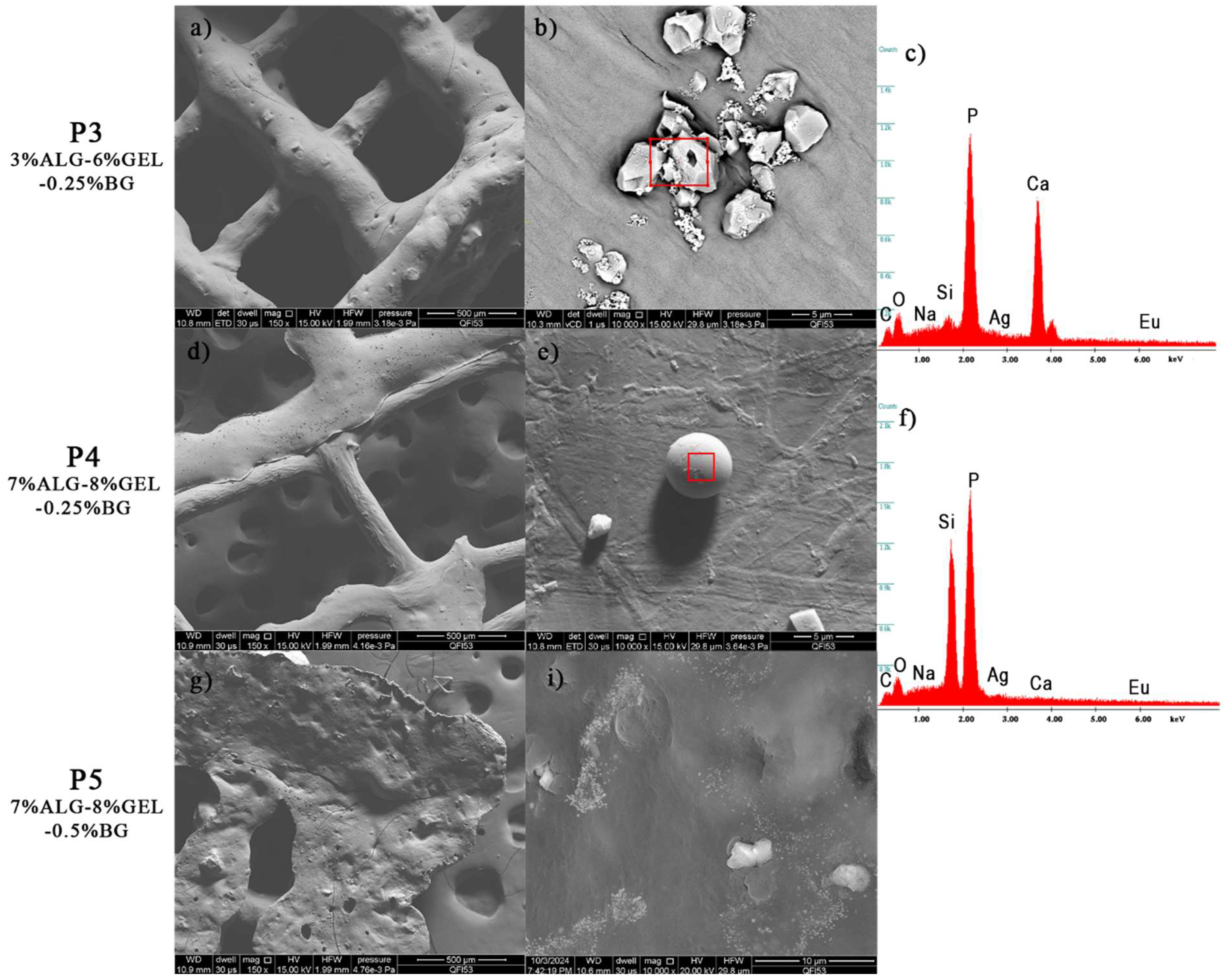
Figure 3. 3.
Scanning electron microscopy of the 3D printed composite scaffolds: a), b), d), e), g), i) and EDS spectra: c), f).
Figure 3. 3.
Scanning electron microscopy of the 3D printed composite scaffolds: a), b), d), e), g), i) and EDS spectra: c), f).
3.2.3. Fourier Transformed Infrared Spectroscopy
The FTIR spectrum of raw alginate (Fig. 3.4.) typically exhibits several characteristic peaks. The broad absorption band around 3200-3400 cm⁻¹ corresponds to O-H stretching vibrations, indicative of hydroxyl groups. The peak near 1410 cm⁻¹ corresponds to symmetric stretching of carboxylate groups. Additionally, the C-O stretching vibrations appear near 1030 cm⁻¹. Gelatin shows distinctive FTIR peaks corresponding to its proteinaceous nature. The amide II band, arising from N-H bending and C-N stretching vibrations, is observed around 1526 cm⁻¹, while the band around 3200-3400 cm⁻¹ corresponds to O-H.
In the FTIR spectrum of the varied alginate-gelatin-bioglass scaffolds, the characteristic peaks of each component can be observed, confirming their successful incorporation. The broad O- H stretching band (3200-3400 cm⁻¹) and the carboxylate stretching bands (1600 and 1410 cm⁻¹) from alginate are present. The amide bands (1650 cm⁻¹ for amide I, 1550 cm⁻¹ for amide II, and 1440 cm⁻¹ for amide III) from gelatin are also clearly visible. Additionally, the Si-O-Si stretching bands from bioglass (around 1025 cm⁻¹) are evident in the scaffold spectrum, indicating the presence of bioglass within the polymer matrix [40]. The overlapping of bands and slight shifts in peak positions suggest interactions between the components, likely through hydrogen bonding and electrostatic interactions.
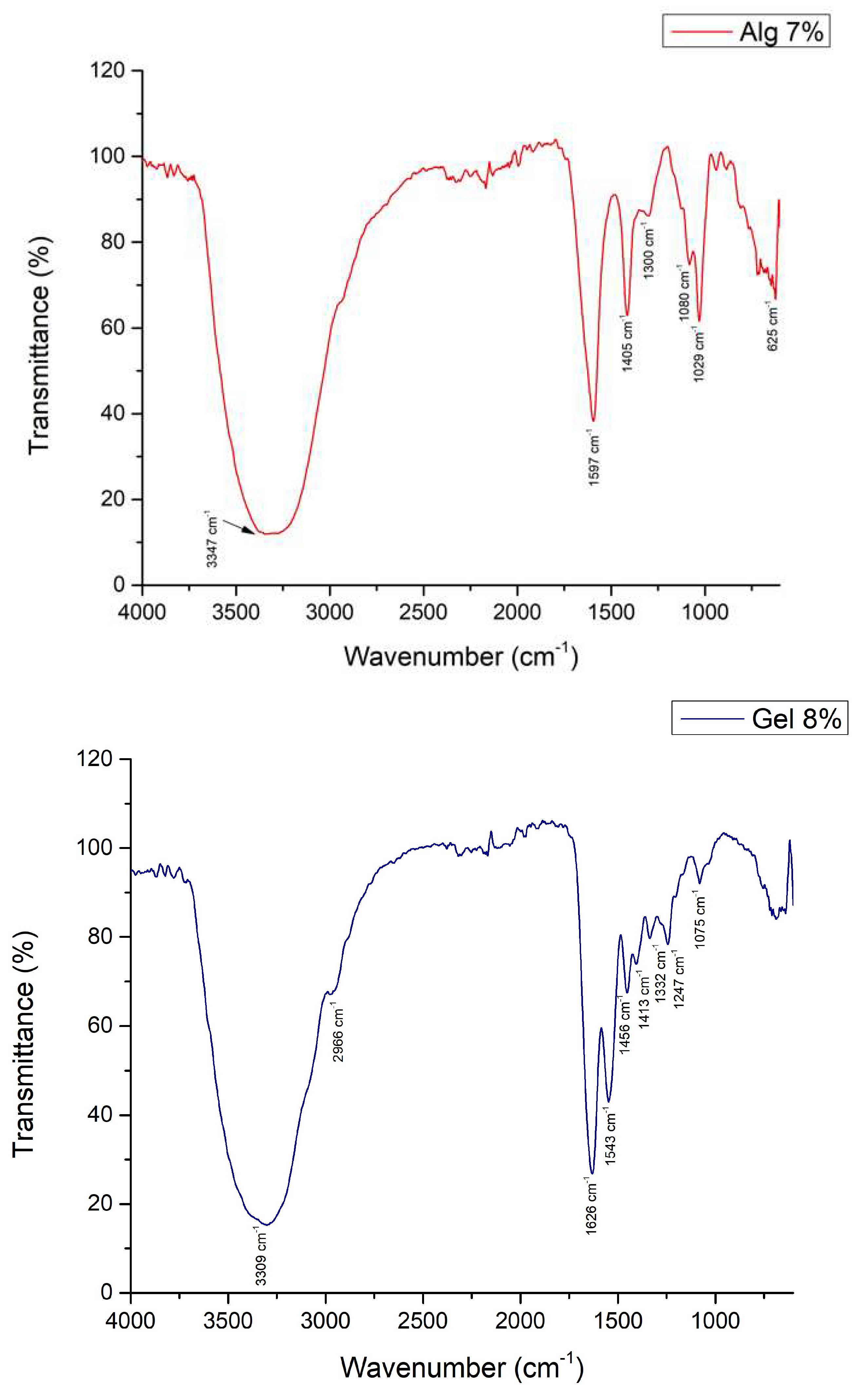
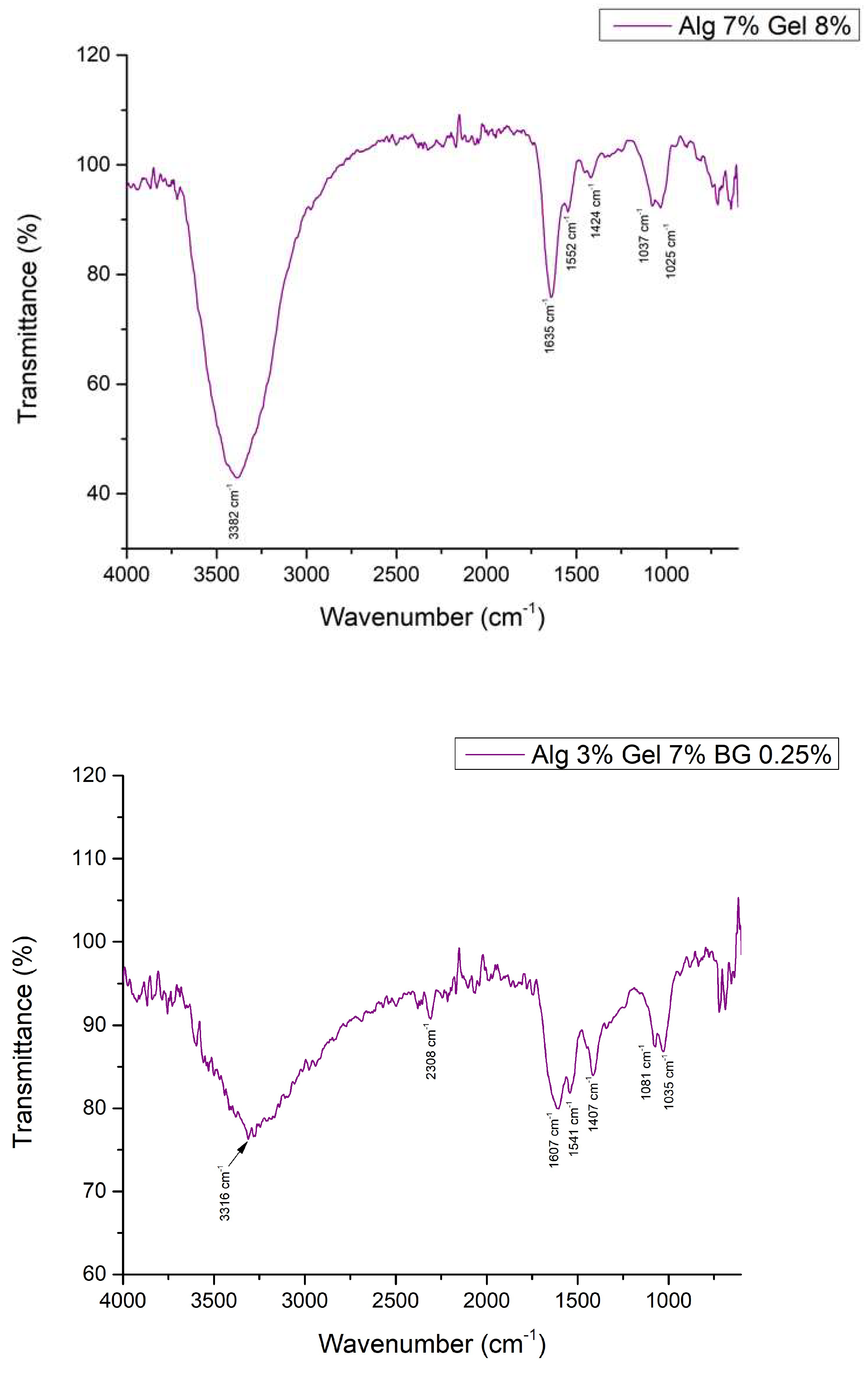
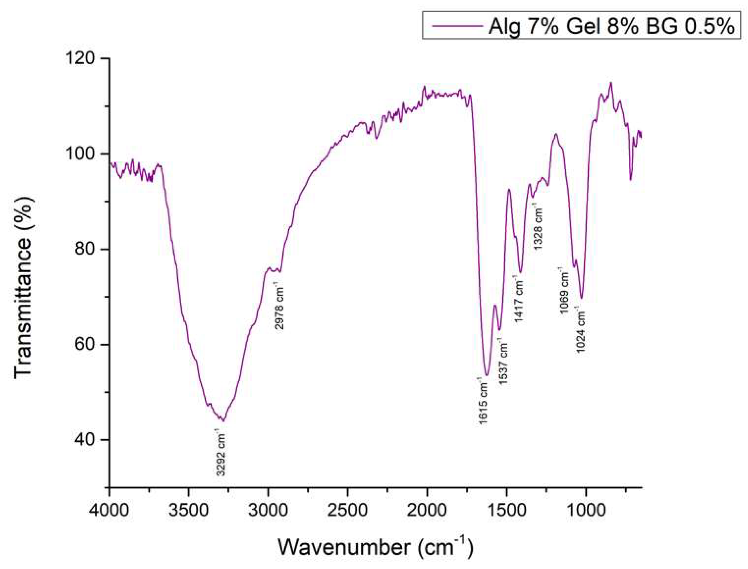
Figure 3. 4.
FTIR spectra of various hydrogel compositions.
3.2.4. Optical Microscopy – Printing Accuracy
In Fig. 3.5. at 4×magnification, the optical microscopy images revealed a homogeneous dispersion of bioglass particles throughout the polymeric matrix. The particles exhibited diverse shapes and sizes. The polymeric alginate and gelatin scaffolds displayed a smooth, continuous structure, indicating a uniform printing process. Higher magnification images (10×) further elucidated the morphology of the scaffolds. The bioglass particles were observed to be well-integrated within the polymeric matrix, with no evidence of agglomeration or clustering. The particles’ surface appeared irregular, with some displaying angular geometries. The polymeric matrix surrounding the bioglass particles exhibited a uniform structure, suggesting a high degree of interconnectivity. The homogeneous distribution of bioglass particles and the smooth is crucial for ensuring consistent bioactivity and mechanical reinforcement across the scaffold. The scaffolds pore structure displayed a decent level of fidelity to the original 3D model, indicating a successful printing process.
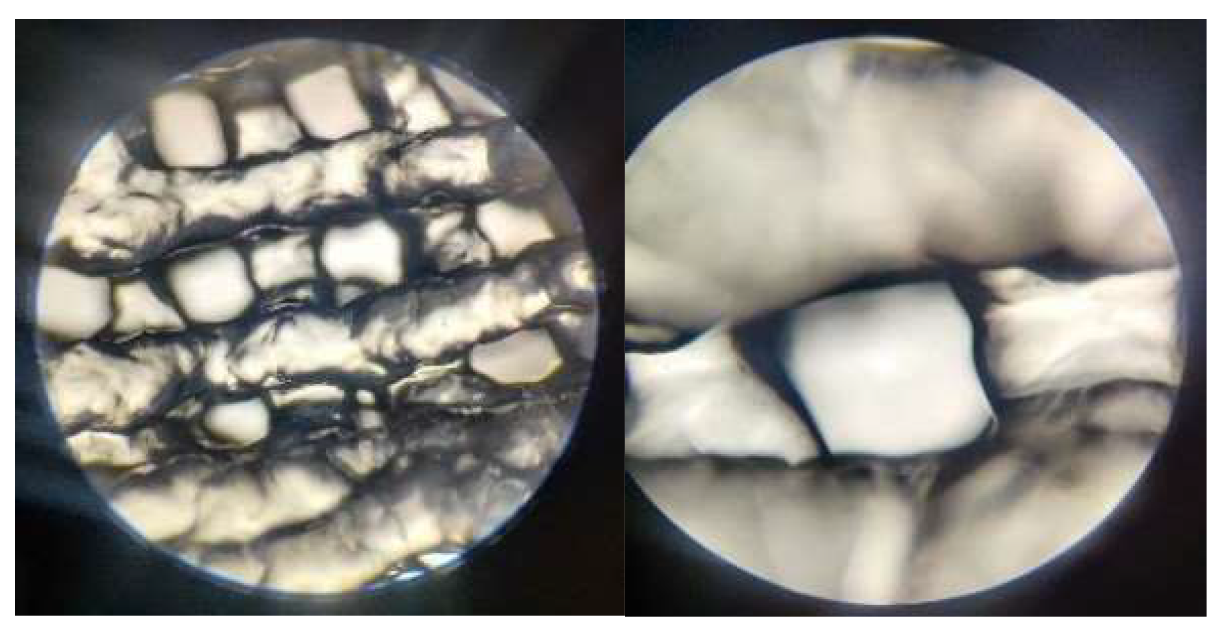
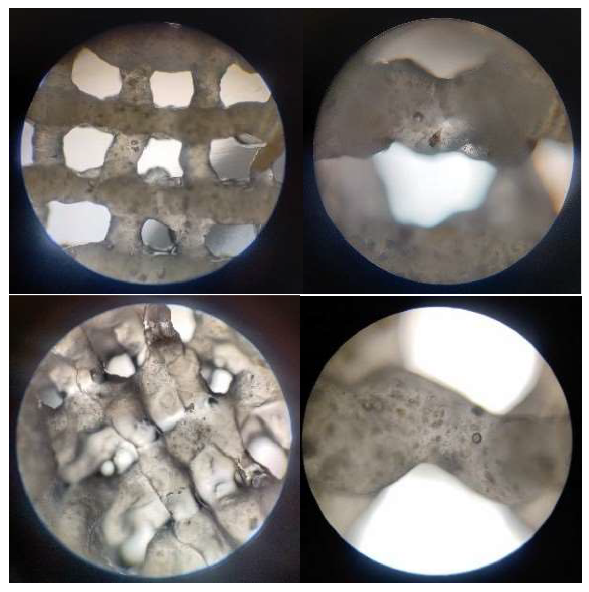
Figure 3. 5.
Optical microscopy images of the 3D printed scaffolds: P2, magnification 4×, 10×; P3, magnification 4×, 10×; P4 magnification 4×, 10×.
Figure 3. 5.
Optical microscopy images of the 3D printed scaffolds: P2, magnification 4×, 10×; P3, magnification 4×, 10×; P4 magnification 4×, 10×.
In addition, the values obtained for the strand thickness, as displayed in the chart from Fig. 3.6. suggest that the hydrogel expanded approximately double the diameter of the 22 G nozzle. This could be explained by the non-newtonian nature of the complex fluids involved, which would cause the shear-thinning effect to manifest. However, this phenomenon seems to be slightly reduced in composite materials.
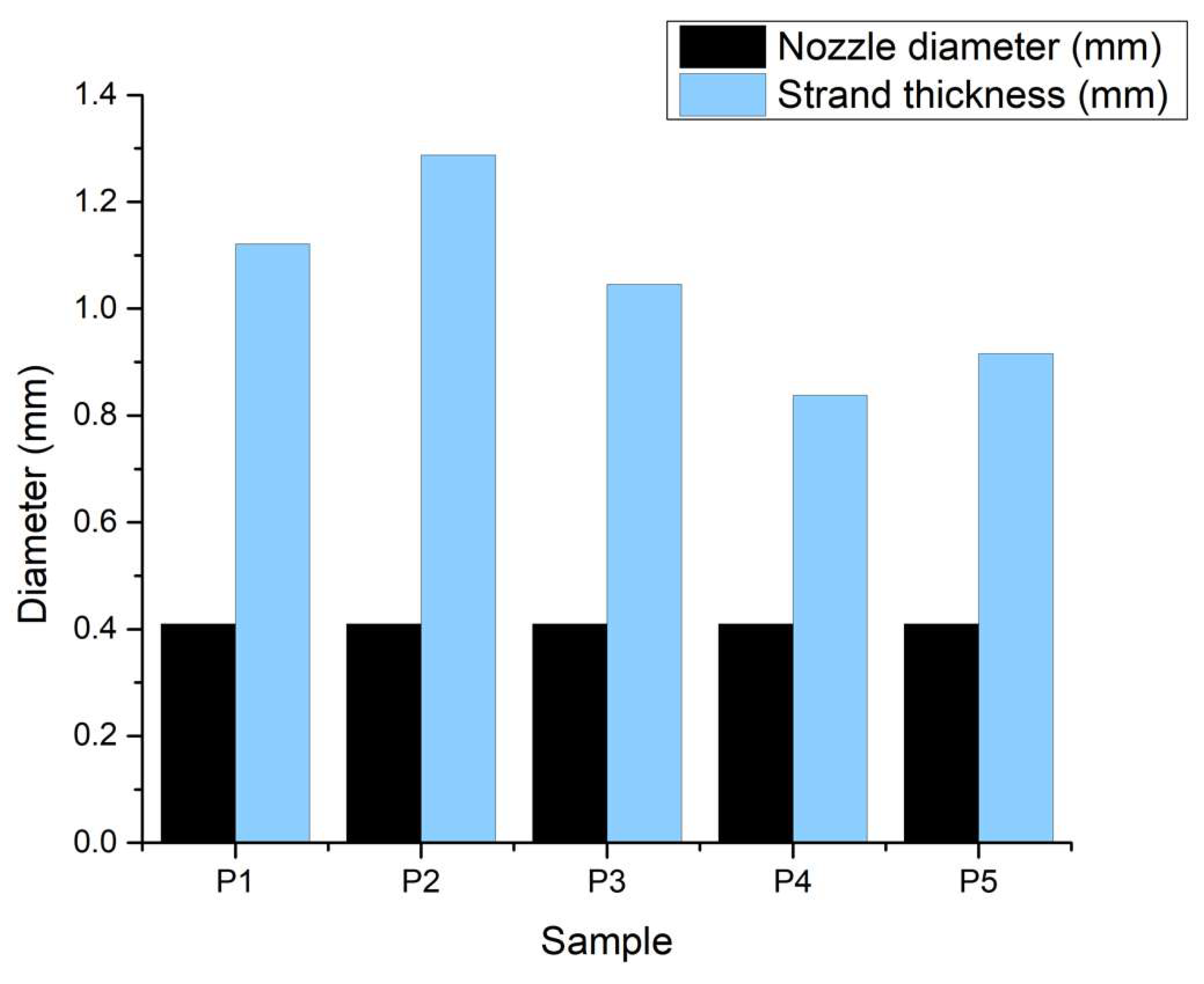
Figure 3. 6.
Print accuracy chart.
3.2.5. Swelling Degree
The swelling degree of polymeric scaffolds is a critical parameter influencing their performance in tissue engineering applications. Results (Fig. 3.7.) indicate that the incorporation of bioglass particles into alginate and gelatin scaffolds modulates the swelling behavior, with higher bioglass content leading to reduced swelling. This trend suggests that bioglass particles restrict the polymer network ability to absorb water, thereby reducing the overall swelling capacity. Across all samples, the swelling degree remained below 250%, indicating a moderate water absorption capacity. The controlled swelling behavior of these scaffolds is critical for tissue engineering applications, as excessive swelling can lead to scaffold degradation and compromised mechanical properties.
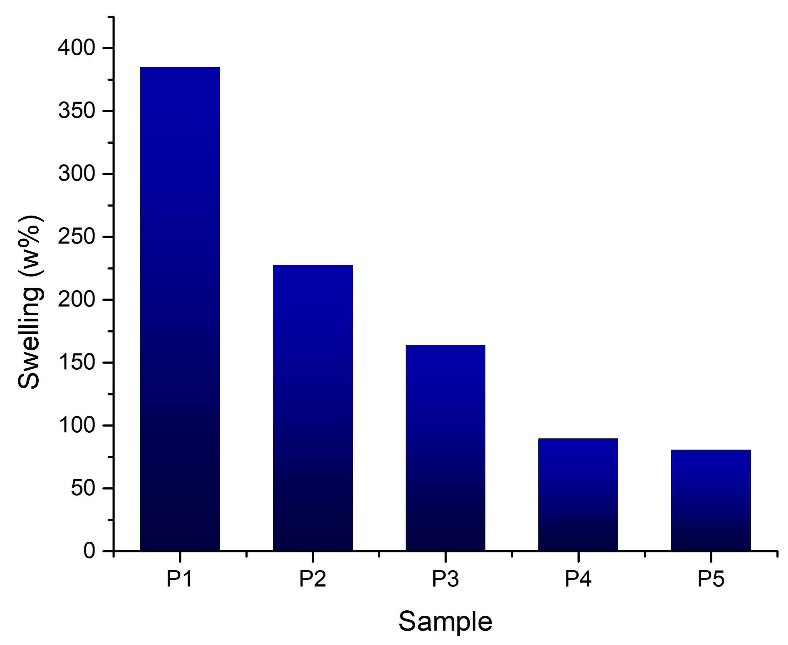
Figure 3. 7.
Swelling values for the 3D printed samples.
3.2.6. Degradation Rate
The degradation test results highlight the significant breakdown of all tested materials over 28 days (Fig. 3.8.). The gelatin scaffold degrades more rapidly, suggesting that gelatin, on its own, has a faster degradation rate under the test conditions. This could be due to the absence of other components that might slow down this process (such as alginate resistance to enzymatic degradation or bioglass ability to modulate the local pH). This correlates with the fact that the gelatin sample also has the highest value of porosity.
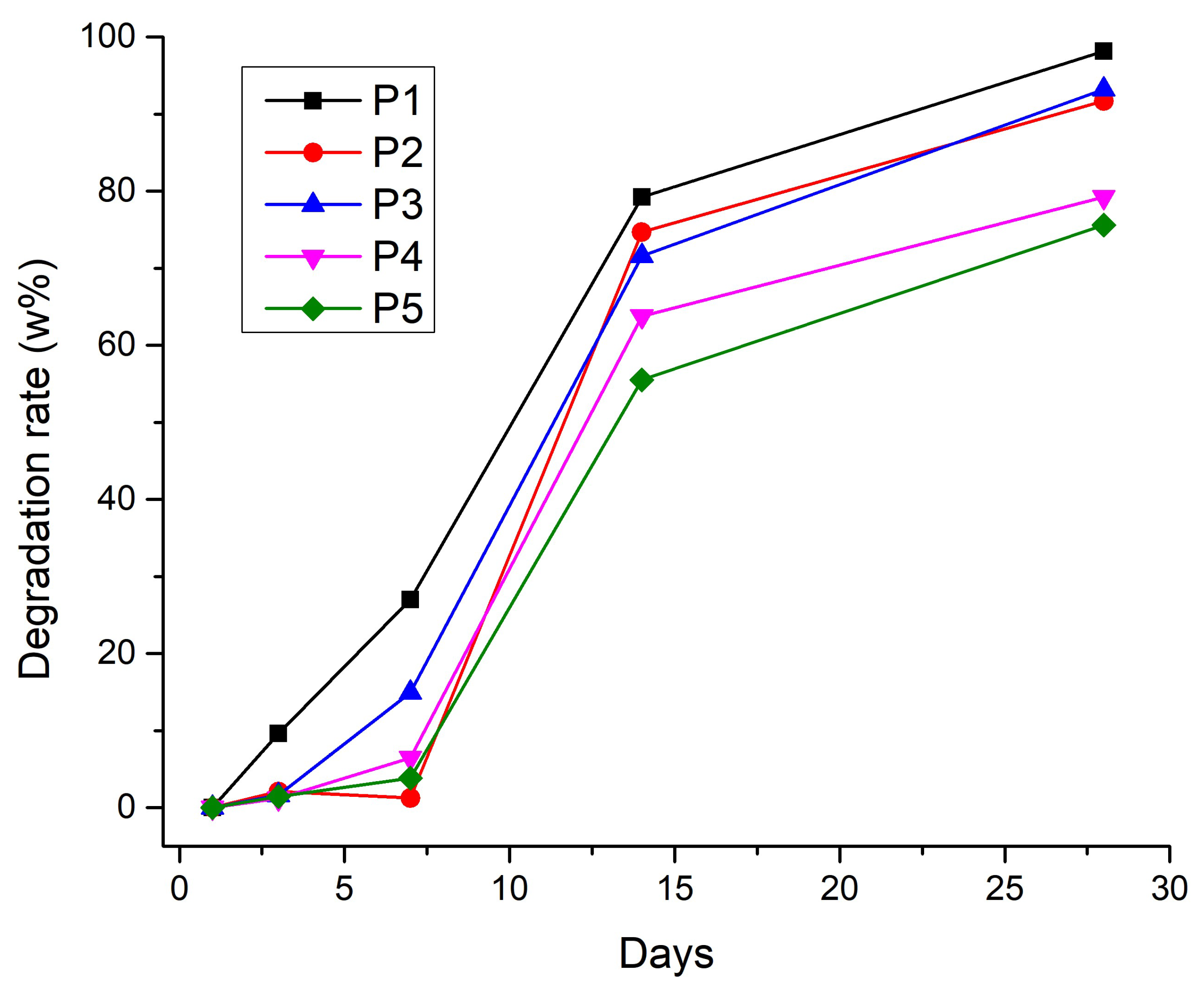
Figure 3. 8.
Degradation rate for the 3D printed samples.
3.2.7. Porosity Evaluation
The theoretical value of porosity is suggested by BioScaffolds V2 as 23.07% for the 22 G nozzle. The resulted values are lower than anticipated due to the expansion of the filament strand expansion after being extruded. A porosity lower than 25% across all samples (Fig. 3.9.) suggests a set of materials that are relatively dense and compact, which can be advantageous for certain applications requiring high strength, durability, or resistance, such as cortical bone areas.
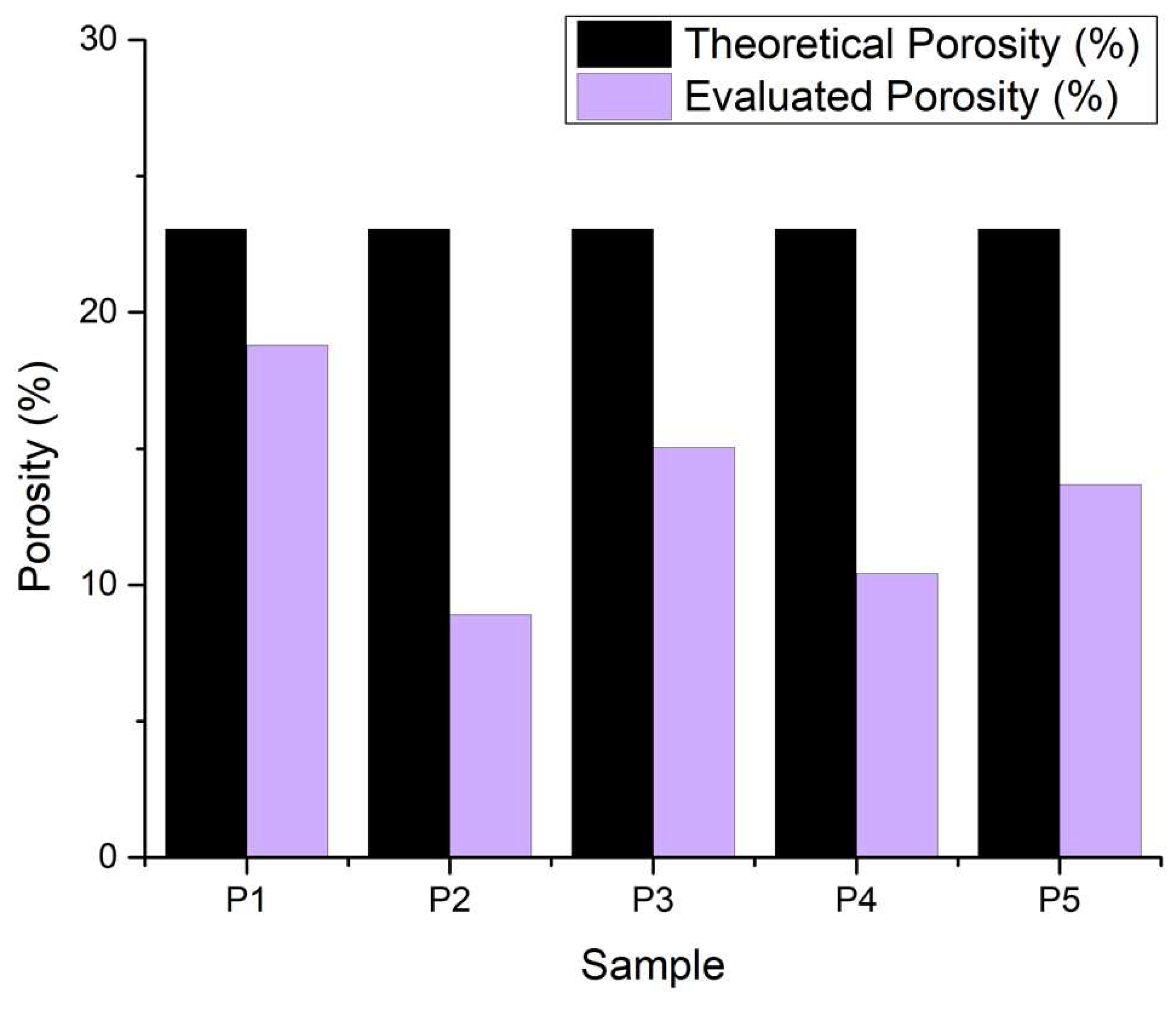
Figure 3. 9.
Porosity for the 3D printed samples.
3.2.8. In Vitro Mineralization
Regarding the composite printed samples (Fig. 3.10.), after 14 days in SBF 1.5X (1.5 times the concentration of phosphate ions compared to normal SBF), apatite formations are present on the composite scaffolds, which is to be expected, as the bioactive glass shows the behavior of mineralization, which results in good osteoinductive properties for the scaffolds.
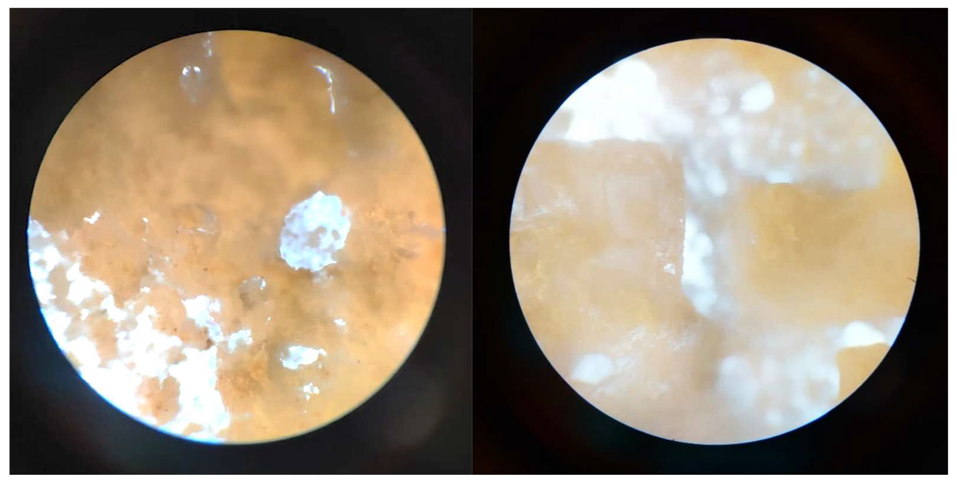
Figure 3. 10.
Optical microscopy images of the 3D printed scaffolds: a. P4, magnification 10×; b. P5, magnification 10x; after 14 days in SBF 1.5X.
Figure 3. 10.
Optical microscopy images of the 3D printed scaffolds: a. P4, magnification 10×; b. P5, magnification 10x; after 14 days in SBF 1.5X.
3.2.8. Cell Seeding and LIVE/DEAD Assay
The samples which demonstrated the best stability for manipulation, after 48 h incubation, were further evaluated for cell viability. Figure 3.11. illustrates good cell viability based on the green color of the fluorescence from Calcein AM, for both hydrogel and composite scaffolds. In addition, osteoblast adhesion was observed and attributed to cell-binding moieties from gelatin, and ion release from the bioglass composition; and cell migration was visible from the difference of focus in the Z-stack. The distribution of viable cells shows promising results for the composite scaffolds, but further in vitro evaluations, such as MTT assay and immunocytochemistry are required to assess their biological potential.
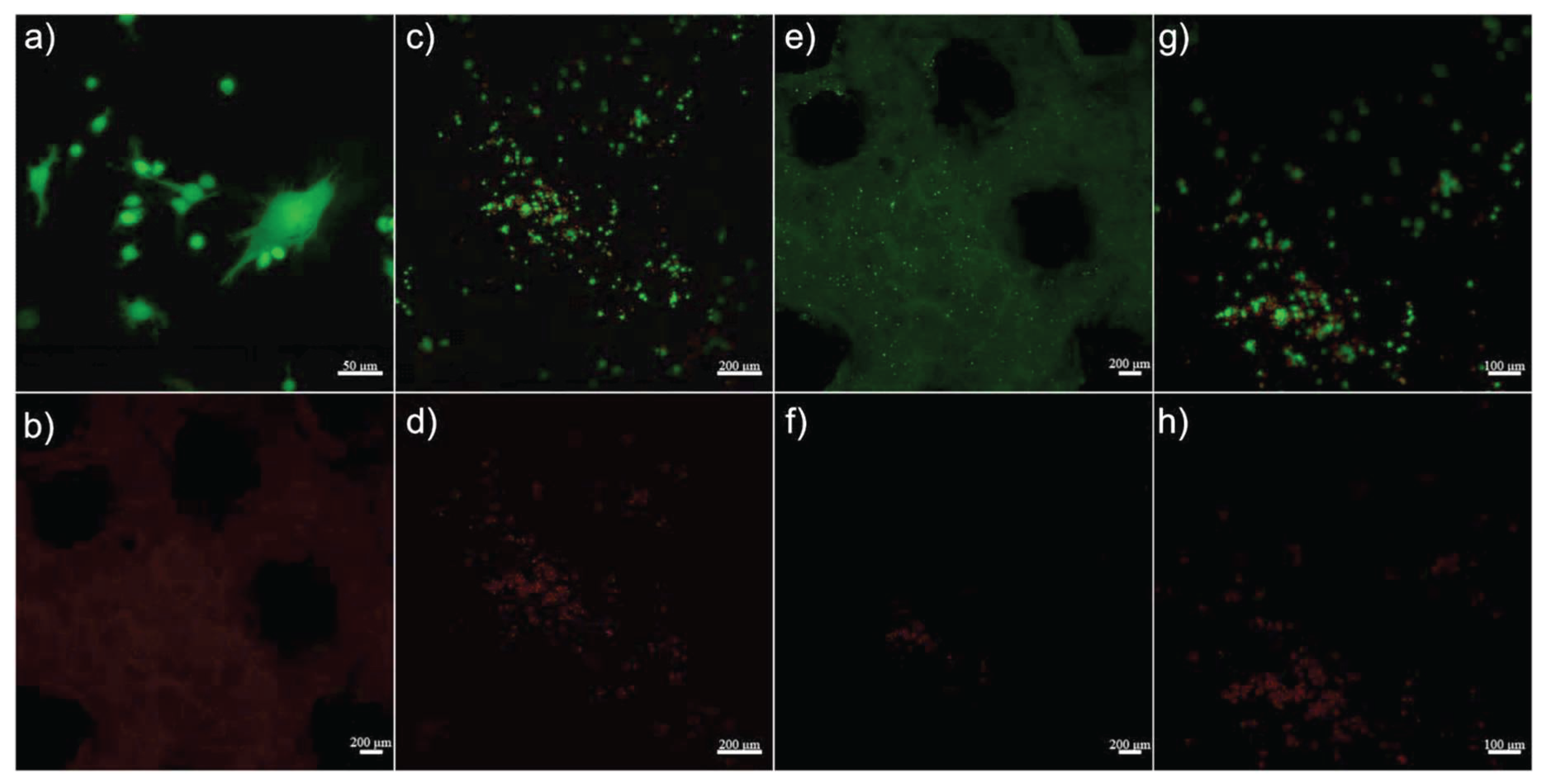
Figure 3. 11.
Confocal microscopy images of the 3D printed scaffolds: a,b) control c,d,e,f) 8% Gel – 7% Alg scaffold and g,h) 6% Gel – 3% Alg – 0.25% BG.
Figure 3. 11.
Confocal microscopy images of the 3D printed scaffolds: a,b) control c,d,e,f) 8% Gel – 7% Alg scaffold and g,h) 6% Gel – 3% Alg – 0.25% BG.
4. Discussion
Authors should discuss the results and how they can be interpreted from the perspective of previous studies and of the working hypotheses. The findings and their implications should be discussed in the broadest context possible. Future research directions may also be highlighted.
5. Conclusions
As the research in this field continues, there is a need to optimize the printability of composite hydrogels with doped bioglass (7% alginate, 8% gelatin, 0.25% BG – Alg-Gel-BG) by tuning parameters such as the bioink composition, printing parameters, and post-processing conditions. Additionally, further studies are required to evaluate the effect of scaffold architecture on long-term performance and biocompatibility in vitro. By addressing these aspects, personalized 3D bioprinting has the potential to provide effective solutions for bone defect regeneration.
Cell adhesion is the main requirement in a number of cellular processes involved in tissue repair, such as cell diffusion, migration, proliferation, and differentiation. Designing applications for bone tissue regeneration requires an understanding of the variables that influence cell behavior as well as how to manage it, including adhesion, orientation, migration, and differentiation on scaffolds.
In terms of prospects, these strategies hold tremendous potential for tissue engineering applications to enhance stem cell differentiation, to locally program cell proliferation and apoptosis to drive morphological development, or to trigger growth factor receptor signaling that mediates structural self-organization. Overall, both the understanding of how the cellular mechanical environment affects cell and tissue behavior and the technical advances required to reproduce those mechanical microenvironments in vitro are advancing rapidly. However, most of these technical advances are still in their infancy and making them widely accessible and applicable in a high-throughput manner will still face many challenges.
In addition, cells can be engineered to express genes with synthetic ion-sensitive promoters, which allows further regulation of cellular responses induced by channel modulation. Although not yet practically implemented for tissue engineering applications, it seems feasible that scaling up such approaches could precisely control or even synthetically regulate mechanosensitive cellular responses within in vitro or implanted tissue constructs.
Future studies should address several aspects that may interfere with the veracity of the results obtained. First, the precise correlation between types of mechanical stresses and their signaling pathways can be further explored by conditions simulating mechanical stresses in vitro using 3D cultures and bone biomimetic materials.
Author Contributions
Conceptualization, C.B.; Methodology, C.B. and R.-E.S.; Formal Analysis, A.T., C.B., I.-C.S., D.M., D.-D.C., R.-E.S., and D.-A.N.; Investigation, A.T., I.-C.S., C.N., E.L., D.M., D.-D.C., R.-E.S., D.-A.N., A.B., and A.P.; Resources, C.B., C.N., E.L., A.B., and A.P.; Data Curation, A.T., C.B., I.-C.S., and R.-E.S.; Writing—Original Draft Preparation, A.T., C.B., I.-C.S., E.L., D.M., D.-D.C., and R.-E.S.; Writing—Review & Editing, A.T., C.B., and I.-C.S.; Visualization, A.T. and I.-C.S.; Supervision, C.B. and E.L. All authors have read and agreed to the published version of the manuscript.
Funding
This research received no external funding.
Data Availability Statement
Data will be made available on request.
Conflicts of Interest
The authors declare that they have no known competing financial interests or personal relationships that could have appeared to influence the work reported in this paper.
Abbreviations
The following abbreviations are used in this manuscript:
| FTIR | Fourier Transformed Infrared Spectroscopy |
| SEM | Scanning Electron Microscopy (SEM) |
| EDS | Energy-dispersive X-ray Spectroscopy |
| SBF | Simulated body fluid |
| EBB | Extrusion-based bioprinting |
| Alg | alginate |
| Gel | gelatin |
| BG | bioglass |
| DNA | deoxyribonucleic acid |
| hFOB 1.19 | Human fetal osteoblastic cells |
| TEOS | Tetraethyl orthosilicate Si(OC2H5)4 |
| TEP | Triethyl phosphate (C2H5)3PO4 |
| DC | direct current |
| ATR | attenuated total reflection |
| PBS | phosphate buffered saline |
| DMEM | Dulbecco’s Modified Eagle’s Medium |
| MTT | (3-(4,5-dimethylthazolk-2-yl)-2,5-diphenyl tetrazolium bromide) |
References
- V. Siracusa, G. Maimone, and V. Antonelli, “State-of-Art of Standard and Innovative Materials Used in Cranioplasty,” Polymers 2021, Vol. 13, Page 1452, vol. 13, no. 9, p. 1452, Apr. 2021. [CrossRef]
- S. Wei, J. X. Ma, L. Xu, X. S. Gu, and X. L. Ma, “Biodegradable materials for bone defect repair,” Military Medical Research, vol. 7, no. 1, pp. 1–25, 2020. [CrossRef]
- C. Mandrycky, Z. Wang, K. Kim, and D. H. Kim, “3D bioprinting for engineering complex tissues,” Biotechnol Adv, vol. 34, no. 4, pp. 422–434, Jul. 2016. [CrossRef]
- A. Hasan et al., “Advances in osteobiologic materials for bone substitutes,” J Tissue Eng Regen Med, vol. 12, no. 6, pp. 1448–1468, 2018. [CrossRef]
- L. Cheng et al., “3D Printing of Micro- and Nanoscale Bone Substitutes: A Review on Technical and Translational Perspectives,” International Journal of Nanomedicine, vol. 16, p. 4289, 2021. [CrossRef]
- J. Konka, J. Buxadera-Palomero, M. Espanol, and M. P. Ginebra, “3D printing of hierarchical porous biomimetic hydroxyapatite scaffolds: Adding concavities to the convex filaments,” Acta Biomater, vol. 134, pp. 744–759, Oct. 2021. [CrossRef]
- I. Matai, G. Kaur, A. Seyedsalehi, A. McClinton, and C. T. Laurencin, “Progress in 3D bioprinting technology for tissue/organ regenerative engineering,” Biomaterials, vol. 226, p. 119536, Jan. 2020. [CrossRef]
- N. Farshidfar, S. Iravani, and R. S. Varma, “Alginate-Based Biomaterials in Tissue Engineering and Regenerative Medicine,” Marine Drugs 2023, Vol. 21, Page 189, vol. 21, no. 3, p. 189, Mar. 2023. [CrossRef]
- Z. U. Arif, M. Y. Khalid, A. Zolfagharian, and M. Bodaghi, “4D bioprinting of smart polymers for biomedical applications: recent progress, challenges, and future perspectives,” React Funct Polym, vol. 179, p. 105374, Oct. 2022. [CrossRef]
- P. Ma, W. Wu, Y. Wei, L. Ren, S. Lin, and J. Wu, “Biomimetic gelatin/chitosan/polyvinyl alcohol/nano-hydroxyapatite scaffolds for bone tissue engineering,” Mater Des, vol. 207, p. 109865, Sep. 2021. [CrossRef]
- R. J. Mccoy, C. Jungreuthmayer, and F. J. O’Brien, “Influence of flow rate and scaffold pore size on cell behavior during mechanical stimulation in a flow perfusion bioreactor,” Biotechnology and Bioengineering, vol. 109, no. 6, pp. 1583–1594, Jun. 2012. [CrossRef]
- S. Vijayavenkataraman, W. C. Yan, W. F. Lu, C. H. Wang, and J. Y. H. Fuh, “3D bioprinting of tissues and organs for regenerative medicine,” Advanced Drug Delivery Reviews, vol. 132, pp. 296–332, Jul. 2018. [CrossRef]
- E. Reina-Romo, I. Papantoniou, V. Bloemen, and L. Geris, Computational design of tissue engineering scaffolds. Elsevier Ltd, 2019. [CrossRef]
- R. Fairag, D. H. Rosenzweig, J. L. Ramirez-Garcialuna, M. H. Weber, and L. Haglund, “Three-Dimensional Printed Polylactic Acid Scaffolds Promote Bone-like Matrix Deposition in Vitro,” ACS Applied Materials and Interfaces, vol. 11, no. 17, pp. 15306–15315, May 2019. [CrossRef]
- G. G. dos Santos et al., “4th Generation Biomaterials Based on PVDF-Hydroxyapatite Composites Produced by Electrospinning: Processing and Characterization,” Polymers 2022, Vol. 14, Page 4190, vol. 14, no. 19, p. 4190, Oct. 2022. [CrossRef]
- H. ; Liu et al., “Recent Advances in Decellularized Matrix-Derived Materials for Bioink and 3D Bioprinting,” Gels 2023, Vol. 9, Page 195, vol. 9, no. 3, p. 195, Mar. 2023. [CrossRef]
- M. E. Brennan Fournet, F. A. Azaman, S. Gunbay, Y. Y. Chen, and D. M. Devine, “Orthopaedic 3D Printing in Orthopaedic Medicine,” Polymer-Based Additive Manufacturing, pp. 121–142, 2019. [CrossRef]
- S. Y. Hann et al., “Dual 3D printing for vascularized bone tissue regeneration,” Acta Biomater, vol. 123, pp. 263–274, Mar. 2021. [CrossRef]
- A. Bhargav, V. Sanjairaj, V. Rosa, L. W. Feng, and J. Fuh YH, “Applications of additive manufacturing in dentistry: A review,” Jul. 01, 2018, John Wiley and Sons Inc. [CrossRef]
- A. L. Jardini, M. A. Larosa, A. Kaasi, and P. Kharmandayan, “Additive Manufacturing in Medicine,” in Encyclopedia of Smart Materials, Elsevier, 2021, pp. 300–320. [CrossRef]
- Ž. P. Kačarević et al., “An Introduction to 3D Bioprinting: Possibilities, Challenges and Future Aspects,” Materials 2018, Vol. 11, Page 2199, vol. 11, no. 11, p. 2199, Nov. 2018. [CrossRef]
- W. L. Ng, A. Chan, Y. S. Ong, and C. K. Chua, “Deep learning for fabrication and maturation of 3D bioprinted tissues and organs,” Jul. 02, 2020, Taylor and Francis Ltd. [CrossRef]
- Z. Gu, J. Fu, H. Lin, and Y. He, “Development of 3D bioprinting: From printing methods to biomedical applications,” Sep. 01, 2020, Shenyang Pharmaceutical University. [CrossRef]
- I. T. Ozbolat, W. Peng, and V. Ozbolat, “Application areas of 3D bioprinting,” Drug Discovery Today, vol. 21, no. 8, pp. 1257–1271, Aug. 2016. [CrossRef]
- Dikyol, M. Altunbek, P. Bartolo, and B. Koc, “Multimaterial bioprinting approaches and their implementations for vascular and vascularized tissues,” Bioprinting, vol. 24, no. May, p. e00159, 2021. [CrossRef]
- I. C. Simcock, S. C. Shelmerdine, D. Langan, G. Anna, N. J. Sebire, and O. J. Arthurs, “Micro-CT yields high image quality in human fetal post-mortem imaging despite maceration,” BMC Medical Imaging, vol. 21, no. 1, Dec. 2021. [CrossRef]
- F. Fahimipour et al., “3D printed TCP-based scaffold incorporating VEGF-loaded PLGA microspheres for craniofacial tissue engineering,” Dental Materials, vol. 33, no. 11, pp. 1205–1216, Nov. 2017. [CrossRef]
- I. Gorroñogoitia, U. Urtaza, A. Zubiarrain-Laserna, A. Alonso-Varona, and A. M. Zaldua, “A Study of the Printability of Alginate-Based Bioinks by 3D Bioprinting for Articular Cartilage Tissue Engineering,” Polymers, vol. 14, no. 2, Jan. 2022. [CrossRef]
- P. S. Gungor-Ozkerim, I. Inci, Y. S. Zhang, A. Khademhosseini, and M. R. Dokmeci, “Bioinks for 3D bioprinting: an overview,” Biomater Sci, vol. 6, no. 5, pp. 915–946, May 2018. [CrossRef]
- A. Schwab, R. Levato, M. D’Este, S. Piluso, D. Eglin, and J. Malda, “Printability and Shape Fidelity of Bioinks in 3D Bioprinting,” Chem Rev, vol. 120, no. 19, pp. 11028–11055, Oct. 2020. [CrossRef]
- A. C. Hernández-González, L. Téllez-Jurado, and L. M. Rodríguez-Lorenzo, “Alginate hydrogels for bone tissue engineering, from injectables to bioprinting: A review,” Feb. 01, 2020, Elsevier Ltd. [CrossRef]
- A. Tariq, S. A. Bhawani, K. M. Alotaibi, and A. Moheman, “Smart biopolymers and their applications,” Smart Polymer Nanocomposites: Biomedical and Environmental Applications, pp. 145–167, Jan. 2021. [CrossRef]
- G. N. Smith et al., “The microscopic distribution of hydrophilic polymers in interpenetrating polymer networks (IPNs) of medical grade silicone,” Polymer, vol. 224, p. 123671, May 2021. [CrossRef]
- G. Suarato, R. Bertorelli, and A. Athanassiou, “Borrowing from nature: Biopolymers and biocomposites as smart wound care materials,” Frontiers in Bioengineering and Biotechnology, vol. 6, no. OCT, p. 137, Oct. 2018. [CrossRef]
- Balakrishnan, N. Joshi, A. Jayakrishnan, and R. Banerjee, “Self-crosslinked oxidized alginate/gelatin hydrogel as injectable, adhesive biomimetic scaffolds for cartilage regeneration,” Acta Biomaterialia, vol. 10, no. 8, pp. 3650–3663, 2014. [CrossRef]
- A. Hajikhani, F. Scocozza, M. Conti, M. Marino, F. Auricchio, and P. Wriggers, “Experimental characterization and computational modeling of hydrogel cross-linking for bioprinting applications,” International Journal of Artificial Organs, vol. 42, no. 10, pp. 548–557, 2019. [CrossRef]
- P. Chen, L. Liu, J. Pan, J. Mei, C. Li, and Y. Zheng, “Biomimetic composite scaffold of hydroxyapatite/gelatin-chitosan core-shell nanofibers for bone tissue engineering,” Materials Science and Engineering: C, vol. 97, pp. 325–335, Apr. 2019. [CrossRef]
- A. Shuaib, D. Motan, P. Bhattacharya, A. McNabb, T. M. Skerry, and D. Lacroix, “Heterogeneity in The Mechanical Properties of Integrins Determines Mechanotransduction Dynamics in Bone Osteoblasts,” Scientific Reports 2019 9:1, vol. 9, no. 1, pp. 1–14, Sep. 2019. [CrossRef]
- G. Kaur, O. P. Pandey, K. Singh, D. Homa, B. Scott, and G. Pickrell, “A review of bioactive glasses: Their structure, properties, fabrication and apatite formation,” J Biomed Mater Res A, vol. 102, no. 1, pp. 254–274, 2014. [CrossRef]
- A. N. Trandaș et al., “Properties of europium and silver doped bioglass thin films obtained by two deposition methods: Biointerfaces for bioinert implants,” Mater Chem Phys, vol. 309, p. 128396, Nov. 2023. [CrossRef]
- G. Qian, L. Zhang, X. Liu, S. Wu, S. Peng, and C. Shuai, “Silver-doped bioglass modified scaffolds: A sustained antibacterial efficacy,” Materials science & engineering. C, Materials for biological applications, vol. 129, Oct. 2021. [CrossRef]
- F. Unal, C. Tasar, and B. Ercan, “Fabrication and in vitro characterization of antibacterial magneto-luminescent core-shell bioactive glass nanoparticles,” Ceram Int, vol. 49, no. 12, pp. 20118–20126, Jun. 2023. [CrossRef]
- L. Wu et al., “The biological functions of europium-containing biomaterials: A systematic review,” Mater Today Bio, vol. 19, p. 100595, Apr. 2023. [CrossRef]
- A. Flores-Jacobo, · Ena, A. Aguilar-Reyes, · Carlos, and A. León-Patiño, “Effect of Dopants on the Physical, Mechanical, and Biological Properties of Porous Scaffolds for Bone Tissue Engineering,” Biomedical Materials & Devices 2022, vol. 1, pp. 1–22, Aug. 2022. [CrossRef]
- T. Kokubo and H. Takadama, “How useful is SBF in predicting in vivo bone bioactivity?,” Biomaterials, vol. 27, no. 15, pp. 2907–2915, 2006. [CrossRef]
- Q. Facts and E. Em, “LIVE/DEAD ® Viability/Cytotoxicity Kit *for mammalian cells*,” 2005.
Disclaimer/Publisher’s Note: The statements, opinions and data contained in all publications are solely those of the individual author(s) and contributor(s) and not of MDPI and/or the editor(s). MDPI and/or the editor(s) disclaim responsibility for any injury to people or property resulting from any ideas, methods, instructions or products referred to in the content. |
© 2025 by the authors. Licensee MDPI, Basel, Switzerland. This article is an open access article distributed under the terms and conditions of the Creative Commons Attribution (CC BY) license (http://creativecommons.org/licenses/by/4.0/).
Copyright: This open access article is published under a Creative Commons CC BY 4.0 license, which permit the free download, distribution, and reuse, provided that the author and preprint are cited in any reuse.


