
Submitted:
16 May 2025
Posted:
19 May 2025
You are already at the latest version
Abstract
Polish Free Electron Laser (PolFEL), which is currently under construction in the National Centre for Nuclear Research in Świerk near Warsaw, will comprise an electron gun and from four to six cryomodules, each accommodating two 9-cell TESLA RF superconducting resonant cavities. To cool the superconducting resonant cavities, the cryomodules will be supplied with superfluid helium having a temperature of 2 K. Other requirements regarding the cooling power of PolFEL result from the need to cool the power couplers for the accelerating cryomodules (5 K) and thermal shields, which limit the heat inleaks due to radiation (40 K – 80 K). The machine will use several thermodynamic states of helium, such as two-phase superfluid helium, supercritical helium and low-pressure helium vapours. Supercritical helium will be supplied from a cryoplant by a Cryogenic Distribution System (CDS): transfer line and valve boxes, where it will be thermodynamically transformed into a superfluid state. This article presents the architecture of the CDS, discusses several design solutions that could have been optimised with the use of Second Law analysis and presents the design methodology of the chosen CDS elements.
Keywords:
helium
; cryogenics
; cryomodule
; transfer line
1. Introduction to Cryogenic Requirements of Big Science Research Infrastructure
Big Science research infrastructures, especially high energy accelerators, free electron lasers, spallation sources and thermonuclear reactors, make extensive use of superconductivity and helium cryogenics. Superconducting high field magnets allow both bending and focusing high energy proton beams, while superconducting radiofrequency cavities are state-of-the-art accelerating structures in presently exploited and constructed machines, like e.g. LHC, XFEL, ESS, PIPII, TORE SUPRA and ITER. Large-scale helium cryogenic systems, which ensure adequate cooling of superconducting devices, are therefore unavoidable in the construction of most Big Science research infrastructure [1,2]. Despite the great hopes associated with the high-temperature superconductors discovered in 1986 [3], the only superconductors from which reliable superconducting high-field magnets and SFR cavities can be constructed are Nb, NbTi and Nb3Sn. The NbTi magnets are cryostated either at 4,5 K or 1,8 K if a magnetic field exceeding about 5 Tesla is required (LHC, TORE SUPRA [4,5]). Magnets made of Nb3Sn are cryostated at 4,5 K or slightly higher, not exceeding 10 K. A thermodynamically optimal operation temperature of superconducting niobium SFR cavities is 2 K. The only cryogen allowing reaching such a low temperature is helium.
Additionally, helium can be transferred over long distances in a supercritical state, allowing both low temperature and single-phase flow. Hence, helium is used in all thermodynamic states depicted in Figure 1.
Superconducting SFR Tesla-type cavities are immersed in superfluid saturated helium He II (e.g. XFEL, ESS [6]). High field accelerator magnets are immersed either in superfluid pressurised He II (e.g. LHC [7]) or pressurised He I (SSC cryostating concept [8,9]). The heat from superconducting devices may be transferred to boiling saturated He I or He II. Helium is transported from cryoplant predominantly in the supercritical state characterised by slightly elevated pressure (about 3 bara), low temperature close to boiling He I, and one-phase flow not requiring phase separators along, in some cases, multikilometer transfer lines. Cooling power requirements of Big Science helium cryogenic systems may exceed 100 kW at 4,5 K.
The above requirements make big helium cryogenics a very challenging system based on advanced materials and technologies, and requiring sophisticated engineering and manufacturing skills.
The superconducting devices, which require cryostating, are connected to the cryoplant through the cryogenic distribution system. It allows the cryogen to be transferred between the cryoplant and the cooled elements of the apparatus. Helium is typically transferred in both directions. It is sent from the cryoplant to the cryomodules for cryostating the superconducting elements. On the other hand, it is sent from the cryomodules to the cryoplant to lower its temperature back to the desired level. The bidirectional transfer of cryogen is possible owing to the multichannel transfer line. It is the main line supplying cryogen along the accelerator. Directly between the transfer line and the cryomodules, there are installed valve boxes. They are cryogenic devices provided, among others, with measurement systems and control valves for regulating the flow rate of the cryogen into individual cryostats of the research apparatus. The cryogenic distribution system not only cryostates the superconducting devices but also delivers a flux of helium from the cryoplant for cooling the thermal shields, which minimise losses of the cooling power.
The length of the transfer line and the number of valve boxes depend on the architecture of the laboratory and the size of the research apparatus. However, the geometrical parameters do not affect the function of the transfer line and of the valve boxes, which are always repeatable, to supply and remove the cryogen used for cryostating the superconductors. Regardless of the transfer line length and the number of valve boxes, each distribution system ends with an endbox, which serves to receive, throttle and vaporize the cryogen not used for cryostating the elements in cryomodules. In effect, the system shows more stability and operating flexibility, and the control over thermal processes is facilitated.
2. General Architecture of Helium Cryogenic Distribution Systems
Any cryogenic system is composed of multiple interdependent subsystems that facilitate the efficient cooling, circulation and recovery of helium as well as the safety, control, and helium storage system. Despite different functionalities, each helium cryogenic system must consist of a certain number of key elements, including the helium refrigeration and liquefaction plant (cryoplant), the cryogenic distribution system and the cryomodules or cryostats housing superconducting devices. A general scheme of the helium cryogenic distribution system is presented in Figure 2.
Helium Refrigeration and Liquefaction Plant (Cryoplant)
The cryoplant serves as the central component of any helium cryogenic system, providing the necessary cooling power to maintain cryogenic conditions. Its primary functions include reducing helium temperature while increasing its density. Helium exiting the cryoplant is typically in a supercritical state to avoid two-phase flows at long distances. Additionally, the cryoplant incorporates a helium recovery and storage system, enabling helium to be stored as pressurised gas during maintenance periods. A liquid helium tank is frequently included to act as a buffer, stabilising fluctuations in cooling power.
Cryogenic Distribution System
The cryogenic distribution system transports helium from the cryoplant to the superconducting components requiring cooling. This bidirectional system facilitates both the supply of cryogen for cryostating and the return of warm helium for recooling. The primary components of the distribution system include:
- Cryogenic transfer lines: Multi-channel insulated pipelines designed to transport helium in various thermodynamic states;
- Valve boxes: Intermediate cryogenic devices equipped with measurement instruments and control valves for regulating helium flow into cryostats. The valve boxes may also comprise heat exchanges and Joule-Thomson valves, allowing conversion of supercritical helium to the liquid or superfluid state;
- The length and configuration of the transfer line, along with the number of valve boxes, depend on the architecture of the research facility and may be of the order of several kilometres (3,4 km in case of a single LHC sector). However, their function remains consistent, enabling precise cryogen delivery to cryomodules and removal. The system concludes with an endbox, which regulates and vaporises unused cryogen, thereby improving system stability and operational flexibility.
Cryomodules / Cryostats
The intended destination for helium transfer through the CDS is the cryomodules or cryostats. These are cryogenic devices in which accelerator components requiring cooling to cryogenic temperatures are enclosed. Cryomodules house Superconducting RF cavities: Critical for particle acceleration. Cryostats house superconducting magnets: dipole, quadrupole magnets that are essential for beam guidance and focusing. A cross-section of a sample cryomodule is shown in Figure 3.
The number of cryomodules and/or cryostats depends on the specific research facility and the number of superconducting components requiring cryostating. Each cryomodule or cryostat functions as an independent cooling unit within the larger cryogenic system.
Helium cryogenic systems operate in a closed-loop configuration to maximise efficiency and minimise helium losses. The operational sequence follows these steps:
- Helium is cooled and liquefied or sub-cooled in the cryoplant as required;
- Cryogenic transfer lines transport helium to valve boxes, where precise pressure and temperature control occur;
- Helium enters cryomodules to cool superconducting components by evaporation;
- Helium vapour is collected and returned to the cryoplant for recompression and re-cooling;
This closed-loop cycle ensures stable and continuous operation of the accelerator’s superconducting elements, optimising both performance and helium utilisation.
As mentioned in section 1, the optimal operating temperature for SRF cavities is 2 K. In cryomodules such as the one shown in Figure 3, the cavities are cooled by submersion in saturated superfluid helium at a temperature of 1.8 – 2.0 K and a pressure of approximately 16 mbar at 1.8 K and 31 mbar at 2.0 K.
The use of helium under such conditions presents numerous engineering challenges. Helium must be transferred from the cryoplant to the cryomodules. During this process, superfluid helium would require precise control of the slope of each process pipe to prevent siphoning. Additionally, transferring helium over long distances would lead to increased losses of superfluid helium due to boil-off. Due to the challenges associated with transporting, modern cryogenic systems primarily rely on supercritical helium transfer. This method prevents unwanted phase transitions and reduces helium losses due to evaporation in the transfer line. Phase conversion from supercritical to superfluid helium occurs near the superconducting components, either within dedicated valve boxes or directly inside cryomodules. Numerous additional challenges must be addressed when designing a cryogenic system for cooling SRF cavities using this method. The cryoplant must ensure the appropriate pressure inside the cryomodules via vacuum pumps. The helium vapours returning from the cryomodule to the cryoplant are highly rarefied due to the very low operating pressure, which results in relatively high flow resistance. During system design, various possible positions for vacuum pumps along the transfer line are considered to minimise thermodynamic losses during the return flow of helium vapours. Another challenge involves the thermalisation of power couplers inside the cryomodules, which must be cooled to different temperatures (typically around 5 K) than the resonant cavities.
3. Optimising Cryogenic Systems: Entropy Analysis
The challenges involved in designing and building cryogenic systems are diverse, ranging from technical and economic issues to material selection. These challenges include ensuring precise temperature, pressure and helium flux control, maintaining system efficiency and ensuring long-term reliability. While solutions can vary and often require balancing factors like cost, materials and performance, most of these challenges can and should be optimised using the second law of thermodynamics. Entropy analysis offers a powerful tool to minimise inefficiencies and enhance system performance. This analysis enables the evaluation of thermodynamic efficiency and identifies the most cost-effective design. By comparing the entropy generation associated with different configurations, engineers can optimise the system for minimal energy losses and operational expenses.
Entropy analysis can be used to optimise a very wide range of thermal-flow devices [12]. An example is the use of entropy analysis by Chen et al. [13] to optimise radiative heat transfer between a tank and a working fluid. Another example of using the entropy minimization method to optimize heat exchangers is the article by Xia et al. [14] in which the authors analyze the effect of heat leakage on entropy generation in the heat exchange process. Johannessen and Balkan [15,16] also successfully use the entropy method to optimize heat exchangers. As shown by Xu et al. [17], the method based on the second law of thermodynamics can also be successfully used for multi-objective analysis and optimization of a heat engine using the Stirling engine as an example. M. Feidt, M. Costea [18] also use the entropy method to try to improve the efficiency of Carnot and Chambadal engines. The above examples show that the optimization and evaluation of thermodynamic systems based on the entropy method finds application in a wide range of thermal-flow systems, which prompted the author to use it in the following considerations.
Entropy analysis is based on the second law of thermodynamics, which states that every irreversible thermodynamic process results in an increase in entropy. In cryogenic systems, the entropy increases caused by irreversible processes must be compensated for by cryocoolers to maintain the constant parameters of the cryogen. The Gouy-Stodola theorem (equation 1) [12,19] provides a framework for calculating the additional power required to mitigate the irreversibilities associated with cryogen flow through transfer pipes.
where:
PAD – additional power required to compensate for the irreversibilities, W
TA – ambient temperature, K
– entropy flux due to irreversibilities, W/K
To minimize the additional work PAD, systems should exhibit minimal entropy flux due to irreversibilities . In cryogenic transfer lines, the rise in entropy is attributed to two primary factors: the pressure drop of the medium within the process pipe and the heat exchange driven by the temperature difference between the cryogenic fluid and its surroundings – see Figure 4. Such a defined increase of entropy can be described by equation (2).
where:
– Entropy increase due to heat transfer, W/K
– Entropy increase due to pressure drop, W/K
The entropy increase caused by heat transfer from the surroundings to the cryogen can be determined using equation (3) [20].
where:
– heat flux, W
TA – ambient temperature, K
TC– temperature of cold medium, K
The entropy increase resulting from the pressure drop during the cryogen's flow through the pipeline can be calculated using equation (4).
where:
– heliums flux, kg/s
T – mean medium temperature, K
ρ – mean medium density, kg/m3
Δp – flow pressure drop in the pipeline, Pa
Each process pipe can be composed of multiple linear pieces, elbow pieces, etc. The fluid flow pressure drop in a given piece can be calculated from the equation 5:
where:
– local pressure drop coefficient of the piece, dimensionless
v – is the fluid velocity, m/s
d – internal diameter of the pipe, m
ρ – fluid density, kg/m3
– linear pressure drop coefficient, dimensionless
L – length, m
For the linear pipe pieces the values are calculated from the Haaland equation:
where:
– the pipe roughness, m,
Re – Reynolds number, dimensionless
The Reynolds number is calculated from the equation 7:
where:
- is the fluid velocity, m/s
- dynamic viscosity of the fluid, Pa.s
The fluid velocity in the circular pipe can be calculated using equation 8:
where:
- is the internal cross-section of a circular pipe piece, m2
In the case of the elbows and T-connections, the pressure drop is calculated using the following equations 9 and 10 [13]:
where:
ε – roughness of the internal wall of the fitting, m
ξ – local pressure drop coefficient of the fitting, dimensionless
for elbow ξ =20Ft
for T-Joint straight connection ξ = 20Ft
for T-Joint branched connection ξ = 60Ft
d – internal diameter of the fitting, m
Entropy analysis performed in this way is a valuable tool for optimizing cryogenic systems. Using the second law of thermodynamics helps identify areas of inefficiency and ensures improvements in energy utilization and system efficiency. This approach ensures that the design and operation of cryogenic systems are both effective and efficient, meeting the complex requirements of cryogenic projects.
4. PolFEL Cryogenic System – Architecture and Challenges
One of the advanced cryogenic systems that aligns with the general principles discussed in previous chapters is the system designed for the Polish Free Electron Laser (PolFEL).
A Free Electron Laser (FEL) is a powerful research tool that merges the capabilities of conventional lasers and synchrotrons. It produces high-intensity, coherent light pulses across a broad wavelength range, from terahertz radiation to X-rays. The core components of an FEL include an electron source, an accelerator that generates a high-quality electron beam and a sequence of undulators that impose a periodic magnetic field, causing the electrons to emit synchronized radiation. This emitted light is used in scientific experiments, while the electron beam itself can be repurposed for generating neutrons or producing ultra-short X-ray pulses. FELs play a crucial role in modern research, enabling breakthroughs in physics, chemistry and biology. Their ability to produce intense, ultra-short pulses allows scientists to capture rapid processes at the atomic and molecular scale. These lasers facilitate high-resolution imaging of nanostructures, support pump-probe experiments to analyze electronic properties of materials and even create extreme states of matter, such as high-energy plasmas. Additionally, FEL-based electron beams open new possibilities for nuclear and materials science studies.
The Polish Free Electron Laser facility project is being developed through the collaboration of eight leading Polish research institutions, with the National Centre for Nuclear Research (NCBJ) coordinating the effort. Wrocław University of Science and Technology is responsible for designing and implementing the cryogenic infrastructure. The project was launched in 2019, with the facility being constructed at the NCBJ campus in Otwock-Świerk, near Warsaw. The PolFEL facility will be the first free-electron laser in Poland. The PolFEL superconducting linear electron accelerator will first consist of an electron gun and four RI-HZDR-type cryomodules, each housing two 9-cell superconducting TESLA RF cavities. Such a configuration allows the generation of a continuous wave and long pulse beam with 5-50 MeV of energy and a long pulse electron beam with energy up to 187 MeV and photon wavelength ranging from the THz region down to 55 nm. In the second stage, an extension is planned with two cryomodules, which allows reaching 300 MeV electron beam energy and an extreme ultraviolet (EUV) range of electromagnetic radiation [21,22,23].
Despite the small size of the project relative to the installations built and used in large research centers such as CERN, ESS, EXFEL or Fermilab [24,25,26,27], PolFEL will comprise all the basic elements of the cryogenic system, which allows the use of RF resonant cavities cryostated at 2 K. The architecture of the PolFEL cryogenic system is schematically shown in Figure 5.
Each PolFEL cryomodule requires helium streams with varying temperatures to cool its individual components to the appropriate temperatures to achieve efficient cooling of superconducting cavities:
- 2 K — Used for cryostating of the superconducting RF cavities,
- 5 K — Used for thermal shielding to intercept heat from power couplers,
- 40–80 K — Used to cool thermal shields and intercept heat from room-temperature components.
A schematic view of the cryomodule with marked pipes (lines) indicating the required helium streams at specified temperatures is shown in Figure 6.
The cryomodules in the PolFEL system are independent cryogenic units and will be cooled in parallel way with the use of a cryogenic distribution system. They will be supplied with cryogen from dedicated valve boxes, via connection elements.
The cryoplant will provide helium to the cryogenic distribution system in two thermodynamic states: supercritical (5 K, 4 bara) and cold gaseous state (40 K, 13 bara). Helium gas will be used to cool the thermal shields of the cryomodules and the distribution system itself. The superfluid 2 K helium, which is required to cryostate the superconducting cavities, will be generated inside the valve boxes dedicated to each cryomodule.
The cryomodules’ cavities will be cooled in the following manner: supercritical helium will be supplied from the cryoplant, through the transfer line and into the valve boxes dedicated for each cryomodule. Inside the valve boxes, the helium flux will be redirected from the main transfer line. Supercritical helium will be in first place delivered to the cryomodules (line “a” in Figure 7) to thermalize the power couplers at the temperature of 5 K. After the thermalization process, supercritical helium will flow back to the valve boxes (line “b” in Figure 7), in which it will be pre-cooled to 2.2 K in a heat exchanger (line “c” in Figure 7) and subsequently throttled in the JT valve into a superfluid state (2 K and 30 mbara) required to cryostate the SRF cavities (line “d” in Figure 7). The superfluid helium thus obtained will be transferred to the cryomodules, in which it will vaporize, receiving the heat generated by the cooled elements. After being vaporized, helium at a pressure of 30 mbara and a temperature of 2 K will flow back to the valve boxes (line “d” in Figure 7). It will subsequently pass through the low-pressure part of the heat exchanger (line “e” in Figure 7) and finally, through the transfer line, to the cryoplant. Helium vapours are returned to the cryoplant under a pressure of approx. 27 mbara and at a temperature of approx. 4 K. Subsequently, they are compressed to approx. 0.3 bara with the use of cold compressors located in the coldbox of the cryoplant. Such a solution will allow the cooling capacity of cold helium vapours to be recovered before their compression to atmospheric pressure in the set of warm vacuum pumps.
5. Design Options for PolFEL CDS Elements and Optimization
The design of cryogenic systems for particle accelerators presents a significant challenge in low-temperature engineering. Although PolFEL is a relatively short accelerator compared to large-scale installations, its cryogenic system includes all the key components outlined in Section 2. As a result, the design challenges encountered in this cryogenic system mirror those of large-scale cryogenic installations, even if on a smaller scale.
The paper focuses on the two challenges addressed in the development of the cryogenic system for the PolFEL cryogenic system:
- cooling method for the power couplers of accelerating cryomodules;
- placement of cold compressors;
These challenges have been successfully overcome and the following sections outline the problems encountered, the approach taken to resolve them and the corresponding calculations demonstrating the solutions.
Power Coupler Cooling Method
Each accelerating cryomodule will consist of two TESLA cavities equipped with a power coupler (see Figure 6), which must be maintained at a temperature of 5 K for optimal operation [28]. Consequently, developing a method for effectively removing heat from these components became imperative. The cryomodule design incorporates an additional cooling loop to supply and remove cryogenic fluid to and from the power couplers. Therefore, during the design phase of the cryogenic distribution system, it was essential to consider the requirement for providing cooling power to these elements. For this purpose, three concepts for the cooling of power couplers were developed. The final selection was made based on an entropy analysis of each of the proposed methods.
Structurally, the simplest solution involves cooling the power coupler using superfluid helium generated in the valve boxes, with a separate system for each cryomodule. In this process, supercritical helium is transferred from the refrigerator and cooled in the heat exchanger within the valve box. Subsequently, it is throttled in the Joule-Thomson (JT) valve, resulting in a vapor-superfluid mixture. This mixture is then transported to the cryomodule to cool the power coupler. Following the removal of heat from the power coupler, the mixture is directed to a superfluid helium tank located within the cryomodule, which is utilized to cryostat the superconducting radio frequency (SRF) cavities. This approach is shown in Figure 10.
In the second solution, an entire cooling loop is incorporated into the transfer line to facilitate the supply and removal of supercritical helium, which is utilized exclusively for the cooling of the power couplers. The cooling loop for the power coupler, situated within the cryomodule, is connected to the additional supply and return lines through a connection that traverses the valve box, as illustrated in Figure 11.
The third solution involves cryostating the power couplers using the same flow of supercritical helium that will be utilized to cryostate the superconducting radiofrequency (SRF) cavities after it has been cooled in the heat exchanger and throttled. For this purpose, a connection will be established within the valve box between the supply line delivering supercritical helium to the heat exchanger and the cooling loop of the power couplers. Initially, the supercritical helium will be employed to cool the power coupler before being directed to the heat exchanger and JT valve, where it will be throttled to achieve a vapour-superfluid mixture. This approach is shown in Figure 12.
An entropy analysis was employed to select the optimal cooling method for power couplers, as described in Section 3. To this end, heat inflows and pressure losses in the cooling fluid flow of the power couplers were estimated. Given the repetitive structure of the accelerator, only the first cryomodule and its associated power coupler were considered during the analysis. The results obtained from the first power coupler are representative of the remaining part of the cryogenic distribution system. The following procedure was used to determine the entropy fluxes generated in the multi-channel transfer line and between the valve box and the coupler. To determine the entropy flux generated in the transfer line for a single power coupler, the total entropy flux for the process line corresponding to the entire mass flow in the specific design case was calculated. Subsequently, based on the cooling fluid demand for the individual power coupler, the entropy flux attributable to a single power coupler was established. In the next step, the entropy flux for the individual power coupler was determined based on the heat inflows and pressure drops during the flow between the valve box and the power coupler. A comprehensive summary of the results from the entropy analyses for each design case is presented in Table 1. The Table 1 illustrates the values of the entropy fluxes based on their sources - heat inflows and pressure drops. It can be observed that heat inflows play a dominant role in each case.
In the case shown in Figure 10, in which a mixture of vapour-superfluid helium is utilized for the cooling of the power coupler, only the entropy flux generated due to heat inputs was determined, owing to the two-phase flow. The determination of the entropy flux based on the pressure drop during two-phase flow is associated with a significant degree of calculation error; thus, this parameter was omitted. Simultaneously, due to the lowest temperature of the coolant in this instance, the entropy flux generated as a result of heat inputs is twice that of the fluxes in the other computational cases, even when pressure drops are taken into account. Therefore, the first design case can be dismissed solely based on the value of the entropy flux generated due to heat inputs.
By knowing the heat inputs, pressure drops and the entropy fluxes generated as a result of them for each of the analysed design cases of power coupler cooling, as derived from equation (3.1), the additional power (PAD) necessary to overcome the irreversibilities accompanying the flow can be determined [29,30]. To ascertain the actual additional power required to overcome the described irreversibilities (PADR), it is essential to consider the thermodynamic efficiency of the cryogenic refrigerator, which, as indicated in Section 1, is 0.3 of the Carnot efficiency. The values of the additional power (PAD) and the actual additional power (PADR), determined based on the total entropy fluxes generated for each design case, are presented in Table 1.
Analysing the results of the entropy analysis presented in Table 1, it can be noted that the cooling solutions for power couplers utilising supercritical helium are similar in terms of the actual additional power required to be supplied to the helium refrigerator. The solution based on cooling power couplers with helium transported through a separate process pipe loop was found to be slightly thermodynamically inferior to the solution involving the use of a typical transmission line for transporting supercritical helium used to cool power couplers and SRF cavities.
The primary difference between the solutions shown in Figure 11 and Figure 12 lies in the higher heat inleaks in the transfer line to the separate loop transporting supercritical helium to cool the power couplers. Furthermore, this solution is also disadvantageous from a structural perspective, as the introduction of two additional process pipes significantly complicates the cross-section of the multi-channel transfer line, resulting in more challenging support configurations for all process pipes and increased complexities during construction and assembly.
Therefore, based on the entropy analysis and optimizing design and execution costs, the cooling solution for power couplers presented in Figure 12 was selected. This solution involves the initial use of supercritical helium for cooling the power couplers, after which the same helium flow will be directed through a heat exchanger and a J-T valve to achieve a vapour-superfluid mixture for cooling the SRF resonant cavities.
Cold Compressors Placement
The second challenge that needed to be addressed using the entropy-based method was the placement of the cold compressors.
The operation of the cryoplant is directly related to the helium parameters, which need to be maintained during the standard operation of the cryomodules. As the superconducting resonant cavities will be cryostated at the temperature of approx. 2 K by being kept in the low-pressure saturated superfluid helium bath (Figure 1), all of the heat generated by the cavities and the heat inleaks from the environment will be compensated by the vaporization of helium. Therefore, helium returning to the cryoplant will have a low temperature and low pressure. A cryoplant serves to transform the returning helium vapours, which have low pressure and temperature and thus low density, into dense supercritical helium at a temperature of approximately 5 K. Three process solutions are most frequently employed, as shown in Figure 13.
The first solution is to use warm vacuum pumps, which serve to maintain low pressure in cryomodules and ensure that cold helium vapours return to the condenser. In this solution, vacuum pumps are protected against excessive cooling by warming helium with the use of electric heaters. After helium passes the vacuum pumps, its pressure is increased in compressors and subsequently, it is gradually cooled and expanded with the use of heat exchangers, turbo-expanders or throttling valves, to obtain a flux of supercritical helium having desired thermodynamic parameters. Being the longest-used method, it is also very well understood. The employed devices do not cause technological or process-related problems. The disadvantage of this solution is the cold exergy loss due to the need to warm up cold helium vapours before they enter the vacuum pumps. In addition, an increase in the temperature of low-pressure cold vapours causes a significant increase in the specific pressure of helium, necessitating the use of vacuum pumps having high volumetric efficiencies [31].
Cold compressors are another solution that may replace warm vacuum pumps. This solution limits the cold exergy loss due to the heating of helium in electric heaters. After passing the cold compressors, the temperature and pressure of helium are sufficient to supply it directly between one of the steps of the cryoplant.
The third solution is a combination of the two above. Cold, low-pressure helium vapours are compressed in cold compressors, reaching a pressure that significantly reduces the volumetric efficiency of the vacuum pumps and the cold exergy of helium is used in the first step of the heat exchanger in the cryoplant. Owing to the pre-compression of cold helium vapours, the required cross-sectional area of the channel is reduced sufficiently to justify its flux in a heat exchanger of acceptable dimensions [32].
The cryoplant for PolFEL will consist of two devices. The first device is a reconditioned refrigerator originally used in Daresbury, United Kingdom, as part of the CLARA infrastructure in the STFC laboratory. It was built around the Linde TCF 50 coldbox and its cooling power should be sufficient to power the PolFEL apparatus in standby mode. The second device will be a new refrigerator with a higher cooling power, allowing the operation of the system in the pulse mode. The need to connect both refrigerators necessitates the use of the first solution, based on warm vacuum pumps. Such a system allows an easy connection between the two refrigerators, as they can be supplied with helium at similar temperatures and pressures. The required thermodynamic parameters will be ensured by vacuum pumps and warm compressor systems.
The intention to utilize the existing refrigerator described above in the project necessitated the use of cold compressors in the helium cooling circuit. During the project preparation, two potential locations for placing the cold compressors were analyzed. The first proposal involved placing the cold compressors in the refrigerator building – the “Integral Cold” Compression method shown in Figure 13. This was motivated by the desire to separate the cooling system from the accelerator system. The second proposal suggested locating the cold compressors near the accelerator hall – “Mixed” Compression method shown in Figure 13.
To determine the optimal placement of cold compressors, an entropy analysis was performed for the vapour return line, based on the previously described algorithm. The analysis was based on the following assumptions:
- Length of the Transfer Line – 25 m
- Number of elbows – 10 pcs
- Pipe size before the cold compressors – DN150
- Pipe size after the cold compressors (if the cold compressors are placed near the accelerating hall)– variable (DN50, DN80, DN150)
- Heat flux to helium (average) – 0.25 W/m²
- Flow rate – 29.5 g/s
- Pressure of helium in the transfer line leaving the accelerating hall – 0.029 bara
- Temperature of helium in the transfer line leaving the accelerating hall – 4.2 K
- The temperature of helium after the cold compressors is calculated in the adiabatic compression process.
- Pressure of helium after the cold compressors – 0.1 bara
Similarly to the previous calculations, the actual additional power required to overcome the described irreversibilities (PADR) was calculated using the efficiency of 0.3 - the Carnot efficiency. The values of the additional power (PAD) and the actual additional power (PADR), determined based on the total entropy fluxes generated for each design case, are presented in Table 2.
As expected, the smallest entropy generation due to the pressure drop was associated with flow through pipes of larger diameters, while the smallest entropy generation due to the temperature difference was associated with flow through pipes of smaller diameters, Calculations of the additional power required to compensate for the generated entropy demonstrated that placing the cold compressors close to the accelerator hall only makes sense if the diameter of the pipe downstream of the cold compressors remains unchanged. However, due to the costs associated with the non-standard approach of locating the cold compressors near the accelerator hall, the possibility of reducing costs related to the size of the process pipe was anticipated. In the absence of such a possibility, it was decided to place the cold compressors inside the cryoplant building.
6. Conclusions
Although the cryogenic system of the PolFEL accelerator is smaller in scale, it shares many characteristics with cryogenic systems used in large accelerators, presenting similar design and operational challenges. For example, one of the design assumptions dictated by the limited space was the need to reduce the external dimensions of the devices being part of the CDS. As a result, the dimensions of the vacuum tanks in the valve boxes were limited and thus the cryogenic equipment – valves, compensation elements and flowmeters – were densely packed. Therefore, the production, welding and assembly required high precision and the process pipes had to be accurately arranged. The internal structure and vacuum vessel of an example valve box from the cryogenic distribution system for the Polfel are shown in Figure 14.
Due to the specific nature of accelerator technology, each system, regardless of its size, requires an individualized approach. The design and optimization process must consider not only key parameters, such as the required cooling power and helium conditions necessary for the proper operation of the resonant cavities, but also practical constraints, including the facility's location and the available space for system installation.
This article highlights challenges encountered from the initial design phase to the selection of an appropriate method for producing superfluid helium for the cryomodules. Given the helium supply parameters provided by the cryoplant and the design of the cryomodules, supercritical helium is converted into superfluid helium inside the valve boxes. Another major challenge arose from integrating two refrigeration units, which required careful selection of a suitable vacuum pump system. This complex configuration necessitated simplifications in other system components, including the vacuum pump system itself. Consequently, a specific cooling method for the power couplers of the accelerating cryomodules was chosen. While this approach adds complexity to the design of the valve boxes, it prevents further complications that could arise from combining two refrigeration units.
As is standard for unique cryogenic systems, the PolFEL design demands a tailored approach due to its specific geometry and helium flow requirements. Addressing various challenges—including material strength, safety considerations and the constraints of manufacturing and assembling valve box components within a limited space—was crucial in the system’s development.
Author Contributions
Conceptualization, M.C.; PolFEL thermo-mechanical design, P.D.; Process calculation, T.B.; Entropy optimization calculation, T.B. and P.D.; methodology, M.C.; original draft preparation, T.B..; review and editing, P.D. and M.C.; Final editing, M.C.; All authors have read and agreed to the published version of the manuscript.
Funding
The PolFEL project received funding from the European Regional Development Fund in the framework of the Smart Growth Operational Programme, Measure 4.2: Development of modern research infrastructure of the science sector. This paper was also supported by statutory funds from the Polish Ministry for Science and Higher Education.
Conflicts of Interest
The authors declare no conflicts of interest.
References
- Lebrun, P. Cryogenics for High-Energy Particle Accelerators: Highlights from the First Fifty Years. IOP Conf. Ser.: Mater. Sci. Eng. 2017, 171, 012001. [Google Scholar] [CrossRef]
- Iwasa, Y. SUPERCONDUCTING MAGNET TECHNOLOGY. In Case Studies in Superconducting Magnets; Springer US: Boston, MA, 2009; pp. 1–24. ISBN 978-0-387-09799-2. [Google Scholar]
- Bednorz, J.G.; Möller, K.A. Possible High Tc Superconductivity in the Ba-La-Cu-O System. Z. Physik B - Condensed Matter 1986, 64, 189–193. [Google Scholar] [CrossRef]
- Rossi, L. Superconducting Magnets for the LHC Main Lattice. IEEE Trans. Appl. Supercond. 2004, 14, 153–158. [Google Scholar] [CrossRef]
- Duchateau, J.L.; Tena, M. Towards Steady State Operation in Large Tokamaks: The Experience of TORE SUPRA Superconducting Magnet System. Fusion Engineering and Design 2006, 81, 2297–2304. [Google Scholar] [CrossRef]
- Weisend Ii, J.G. High Field Magnets. In Superfluid; Springer International Publishing: Cham, 2023; pp. 127–134. ISBN 978-3-031-42651-3. [Google Scholar]
- Poncet, A.; Parma, V.; Weisend, J.G.; Barclay, J.; Breon, S.; Demko, J.; DiPirro, M.; Kelley, J.P.; Kittel, P.; Klebaner, A.; et al. SERIES-PRODUCED HELIUM II CRYOSTATS FOR THE LHC MAGNETS: TECHNICAL CHOICES, INDUSTRIALISATION, COSTS. In Proceedings of the AIP Conference Proceedings; AIP: Chattanooga (Tennessee), 2008; Vol. 985, pp. 739–746. [Google Scholar]
- Jayakumar, R.J.; Abramovich, S.; Ahmad, A.; Archer, B.; Clay, W.; Goodzeit, C.; Harvey, A.; Jalloh, A.; Shu, Q.-S.; Snitchler, G.; et al. Superconducting Magnets, Cryostats, and Cryogenics for the Interaction Region of the SSC. In Advances in Cryogenic Engineering; Kittel, P., Ed.; Springer US: Boston, MA, 1994; pp. 701–708. ISBN 978-1-4613-6074-2. [Google Scholar]
- Wagner, U.; Keyer, W. Process Design Features of the SSC MTL Cryogenic System. In Supercollider 3; Nonte, J., Ed.; Springer US: Boston, MA, 1991; pp. 873–883. ISBN 978-1-4613-6668-3. [Google Scholar]
- Lebrun, P. Superfluid Helium as a Technical Coolant; CERN: Geneva, 1997. [Google Scholar]
- Stengler, T.; Aulenbacher, K.; Hug, F.; Kürzeder, T.; Simon, D. Cryomodule Fabrication and Modification for High Current Operation at the Mainz Energy Recovering Superconducting Accelerator MESA. Proceedings of the 18th Int. Conf. on RF Superconductivity 2018, SRF2017, 4 pages, 0.934 MB. [CrossRef]
- Bejan, A. Second Law Analysis in Heat Transfer. Energy 1980, 5, 720–732. [Google Scholar] [CrossRef]
- Chen, L.; Xia, S.; Shi, S. Minimum Entropy Generation Paths for Generalized Radiative Heat Transfer Processes with Heat Leakage. Results in Engineering 2024, 21, 101759. [Google Scholar] [CrossRef]
- Xia, S.; Chen, L.; Sun, F. Entropy Generation Minimisation for Heat Exchangers with Heat Leakage. International Journal of Ambient Energy 2021, 42, 789–794. [Google Scholar] [CrossRef]
- Johannessen, E.; Nummedal, L.; Kjelstrup, S. Minimizing the Entropy Production in Heat Exchange. International Journal of Heat and Mass Transfer 2002, 45, 2649–2654. [Google Scholar] [CrossRef]
- Balkan, F. Comparison of Entropy Minimization Principles in Heat Exchange and a Short-Cut Principle: EoTD. Int. J. Energy Res. 2003, 27, 1003–1014. [Google Scholar] [CrossRef]
- Xu, H.; Chen, L.; Ge, Y.; Feng, H. Multi-Objective Optimization of Stirling Heat Engine with Various Heat and Mechanical Losses. Energy 2022, 256, 124699. [Google Scholar] [CrossRef]
- Feidt, M.; Costea, M. Progress in Carnot and Chambadal Modeling of Thermomechanical Engine by Considering Entropy Production and Heat Transfer Entropy. Entropy 2019, 21, 1232. [Google Scholar] [CrossRef]
- Mahmud, S.; Fraser, R.A. Second Law Analysis of Heat Transfer and Fluid Flow inside a Cylindrical Annular Space. Exergy, An International Journal 2002, 2, 322–329. [Google Scholar] [CrossRef]
- Duda, P.; Chorowski, M.; Polinski, J. Design and Thermodynamic Performance Analysis of Multichannel Cryogenic Transfer Line for XFEL AMTF. IOP Conf. Ser.: Mater. Sci. Eng. 2017, 171, 012043. [Google Scholar] [CrossRef]
- Romaniuk, R.S. POLFEL - Free Electron Laser in Poland. Photon. Lett. Poland 2009, 1. [Google Scholar] [CrossRef]
- Banaszkiewicz, T.; Chorowski, M.; Duda, P.; Poliński, J.; Pietrowicz, S.; Czuma, P.; Krawczyk, P.; Lorkiewicz, J.; Nietubyć, R.; Sekutowicz, J.; et al. Cryogenic System for Polish Free Electron Laser Facility. IOP Conf. Ser.: Mater. Sci. Eng. 2020, 755, 012102. [Google Scholar] [CrossRef]
- Wrochna, G.; Jagielski, J.; Krzywinski, J.; Nietubyc, R.; Plawski, E.; Szewinski, J.; Pelka, J.; Sobierajski, R.; Sekutowicz, J. On the POLFEL Free Electron Laser Project. Synchrotron Radiation in Natural Science 2009, 8, 3–7. [Google Scholar]
- Martinez, A.; Creus Prats, J.; Soyars, W.; Dhuley, R.; Hansen, B.; Jia, Y.; Chakravarty, A.; Goyal, M.; Banaszkiewicz, T.; Duda, P.; et al. Overview and Status of the PIP-II Cryogenic System. IOP Conf. Ser.: Mater. Sci. Eng. 2024, 1301, 012106. [Google Scholar] [CrossRef]
- Fydrych, J.; Arnold, P.; Hees, W.; Tereszkowski, P.; Wang, X.L.; Weisend Ii, J.G. Cryogenic Distribution System for the ESS Superconducting Proton Linac. Physics Procedia 2015, 67, 828–833. [Google Scholar] [CrossRef]
- Horlitz, G.; Peterson, T.; Trines, D. The TESLA 500 Cryogenic System Layout. In Advances in Cryogenic Engineering; Kittel, P., Ed.; A Cryogenic Engineering Conference Publication; Springer US: Boston, MA, 1996; Vol. 41, pp. 911–920. ISBN 978-1-4613-8022-1. [Google Scholar]
- Erdt, W.; Riddone, G.; Trant, R. The Cryogenic Distribution Line for the LHC: Functional Specification and Conceptual Design. In Advances in Cryogenic Engineering; Shu, Q.-S., Ed.; Springer US: Boston, MA, 2000; pp. 1387–1394. ISBN 978-1-4613-6892-2. [Google Scholar]
- Peterson, T.J.; Weisend, J.G. TESLA & ILC Cryomodules. In Cryostat Design; Weisend Ii, J.G., Ed.; International Cryogenics Monograph Series; Springer International Publishing: Cham, 2016; pp. 117–145. ISBN 978-3-319-31148-7. [Google Scholar]
- Kirkconnell, C.S. Thermodynamic Optimization of Multi-Stage Cryogenic Systems. In Proceedings of the AIP Conference Proceedings; AIP: Madison, Wisconsin (USA), 2002; Vol. 613, pp. 1123–1132. [Google Scholar]
- Hånde, R.; Wilhelmsen, Ø. Minimum Entropy Generation in a Heat Exchanger in the Cryogenic Part of the Hydrogen Liquefaction Process: On the Validity of Equipartition and Disappearance of the Highway. International Journal of Hydrogen Energy 2019, 44, 15045–15055. [Google Scholar] [CrossRef]
- Gistau Baguer, G. Cryogenic Helium Refrigeration for Middle and Large Powers; International Cryogenics Monograph Ser; Springer International Publishing AG: Cham, 2020; ISBN 978-3-030-51676-5. [Google Scholar]
- Arenius, D.M. Cryogenic Plants for SRF Linacs.; Thomas Jefferson National Accelerator Facility (TJNAF), Newport News, VA (United States), December 2014.
Figure 1.
P-T phase diagram of helium [10].
Figure 1.
P-T phase diagram of helium [10].
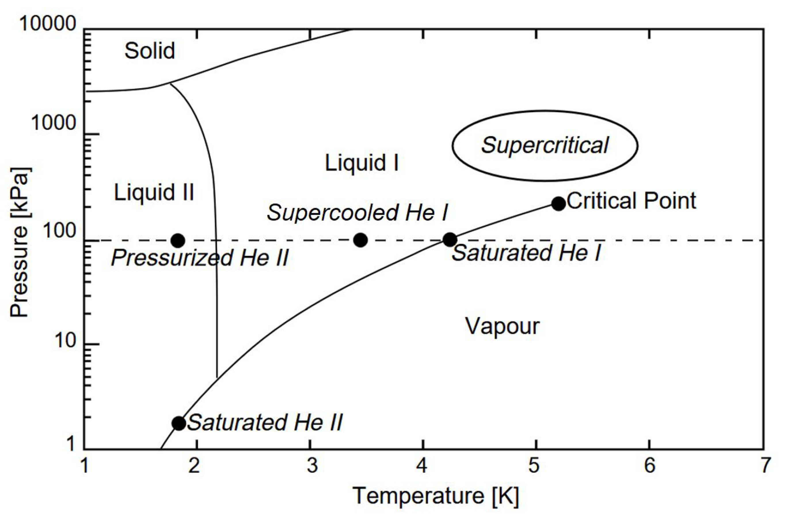
Figure 2.
View of a generic cryogenic distribution system with a 4-channel helium transfer line [9].
Figure 2.
View of a generic cryogenic distribution system with a 4-channel helium transfer line [9].

Figure 3.
Cross-section of cryomodule with RF cavities [11].
Figure 3.
Cross-section of cryomodule with RF cavities [11].
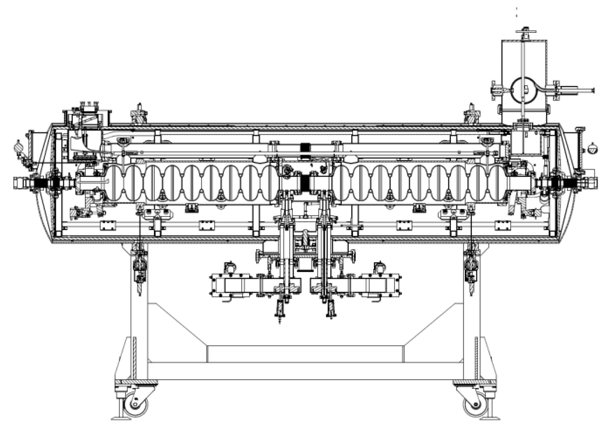
Figure 4.
Processes of entropy increase in cryogenic transfer line having length dx; ṁ – mass flow rate of the transferred medium in kg/s, – heat flux in W, TC – medium temperature in K, p – pressure in Pa, indexes in – input value, out – output value.
Figure 4.
Processes of entropy increase in cryogenic transfer line having length dx; ṁ – mass flow rate of the transferred medium in kg/s, – heat flux in W, TC – medium temperature in K, p – pressure in Pa, indexes in – input value, out – output value.
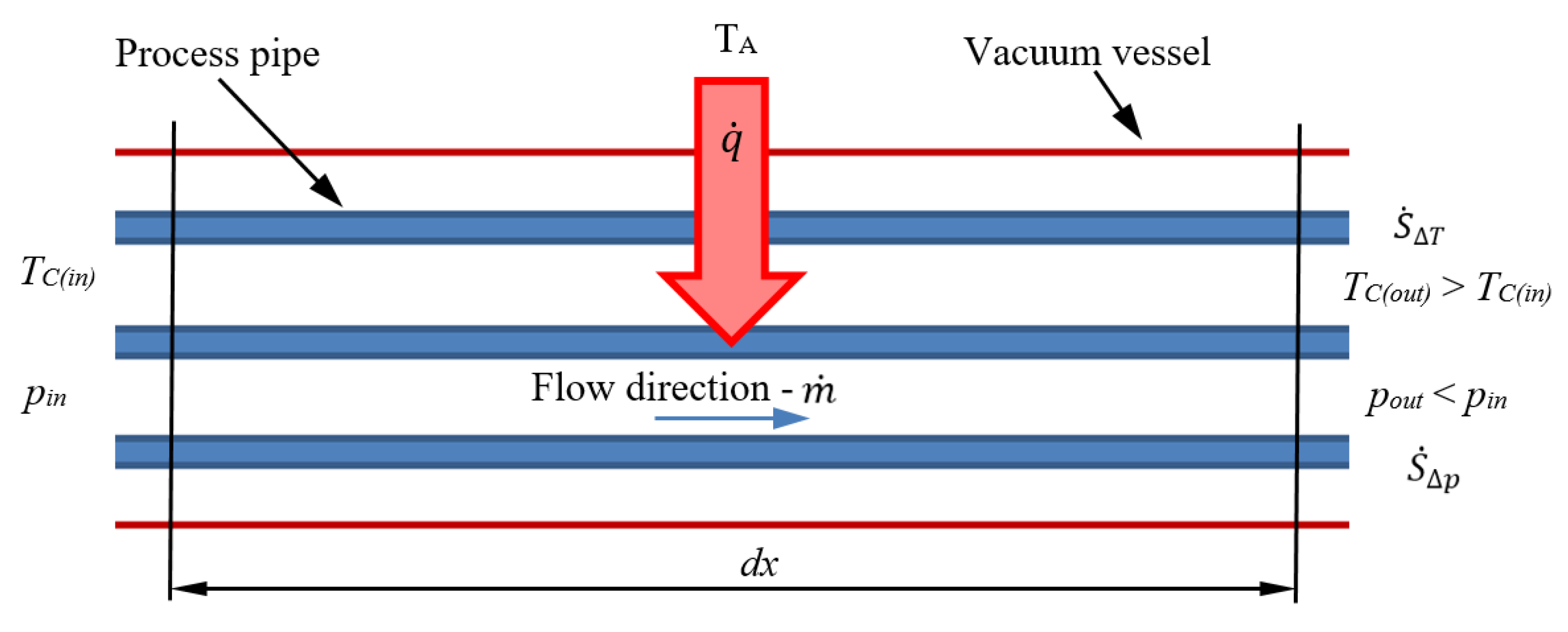
Figure 5.
Top view of the Polfel cryogenic system; 1- multichannel cryogenic transfer line, 2 – gun valvebox, 3 – valveboxes, 4 – endbox, 5 – gun cryomodule, 6 – cryomodule, 7 – cryoplant (1 – 4: parts of CDS).
Figure 5.
Top view of the Polfel cryogenic system; 1- multichannel cryogenic transfer line, 2 – gun valvebox, 3 – valveboxes, 4 – endbox, 5 – gun cryomodule, 6 – cryomodule, 7 – cryoplant (1 – 4: parts of CDS).
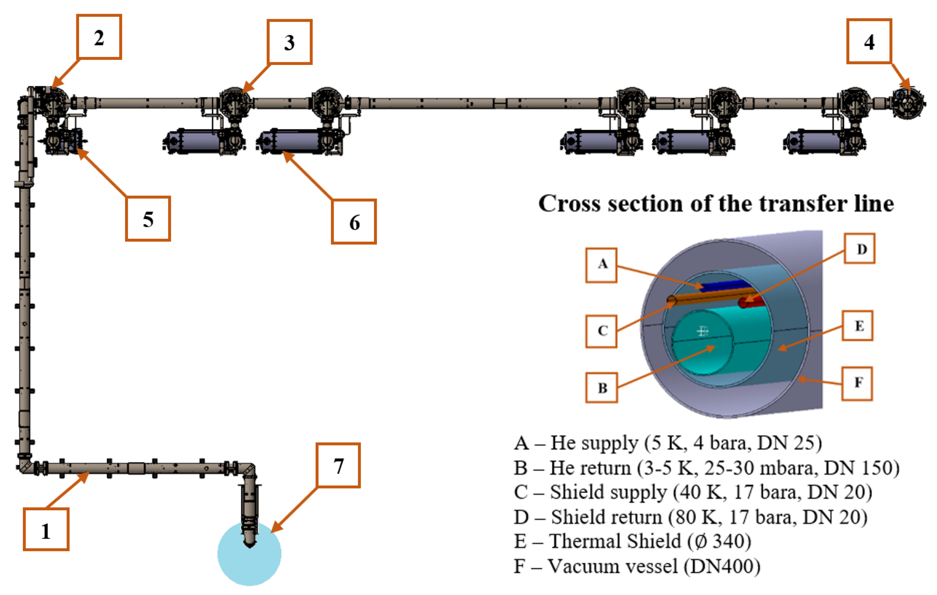
Figure 6.
Schematic view of the cryomodule with required temperatures.
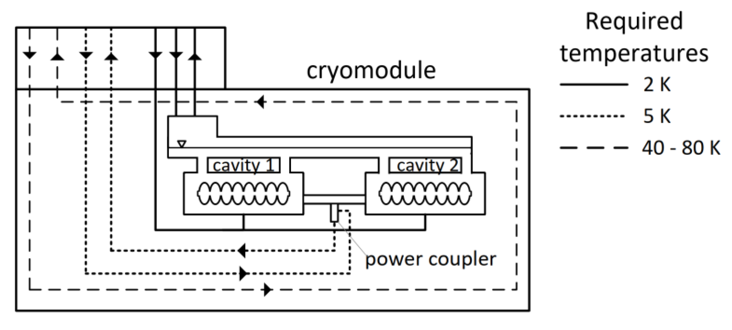
Figure 7.
Flow scheme of the cryomodule cavity cooling system.
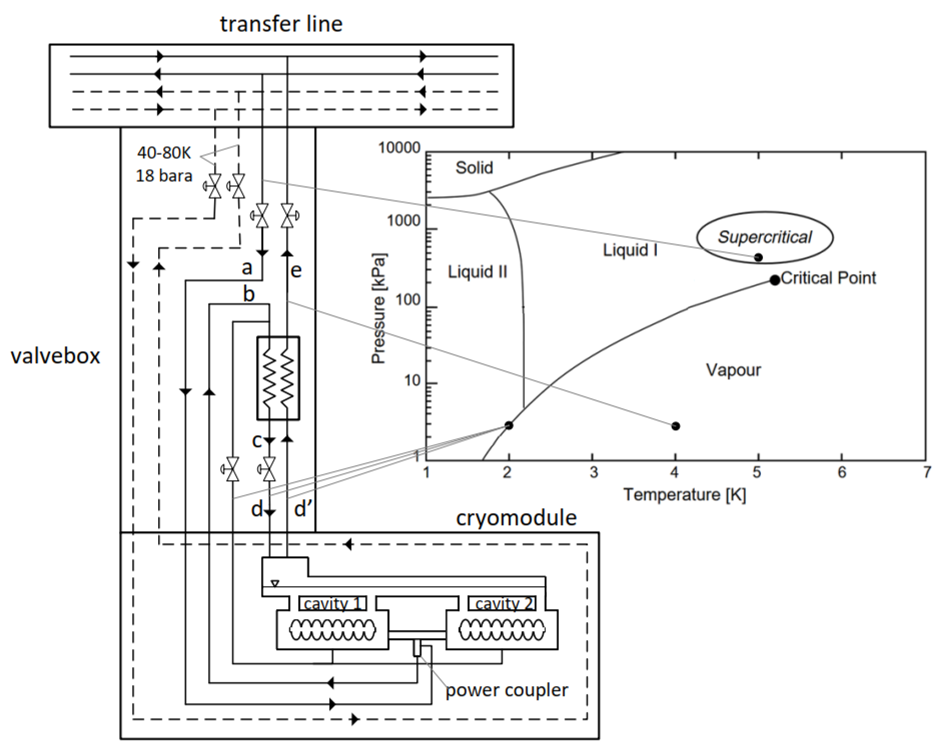
Figure 8.
Cooling scheme of cryomodule cavities – T-S diagram.
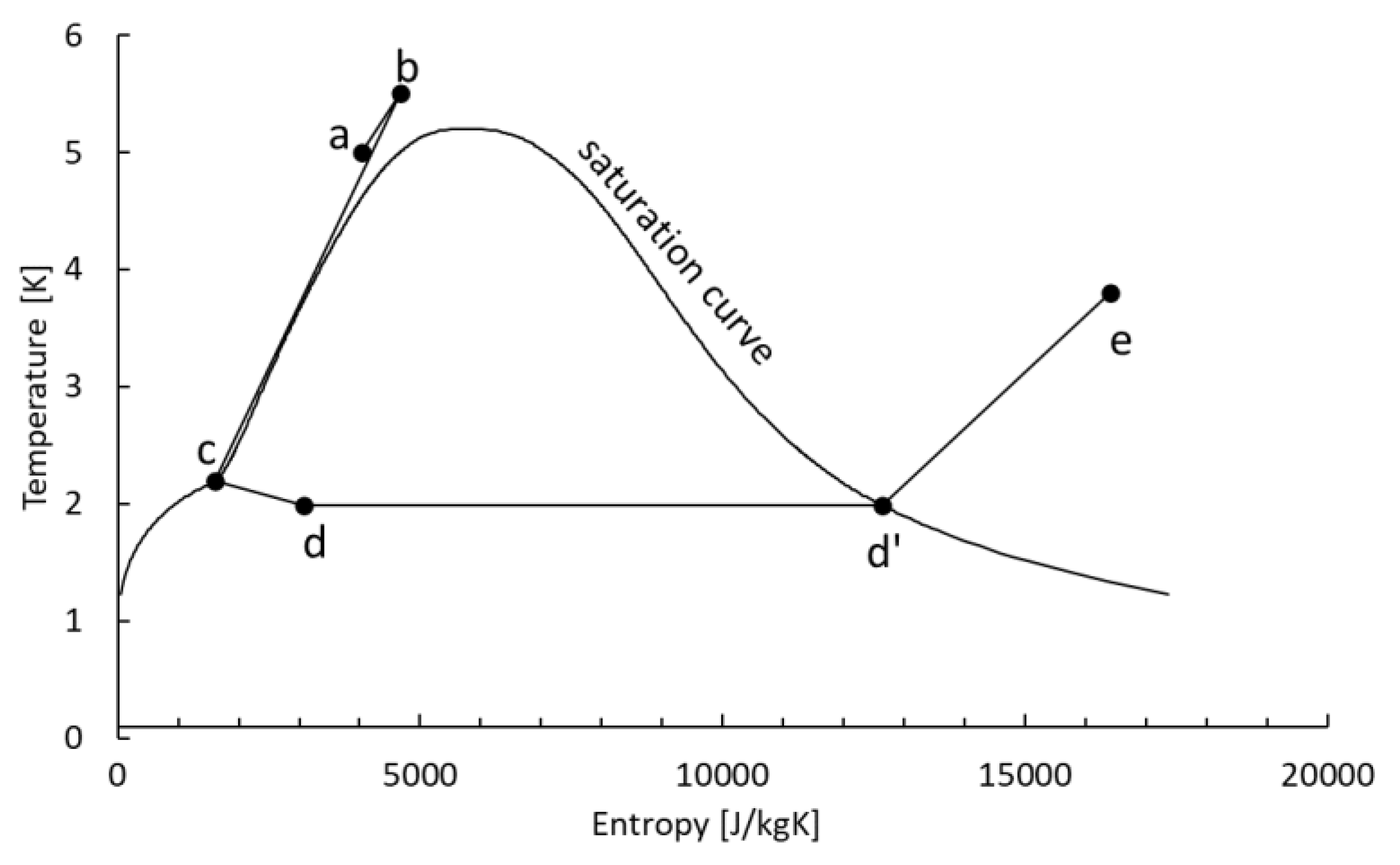
Figure 9.
Cooling scheme of cryomodule cavities – logP-H diagram.
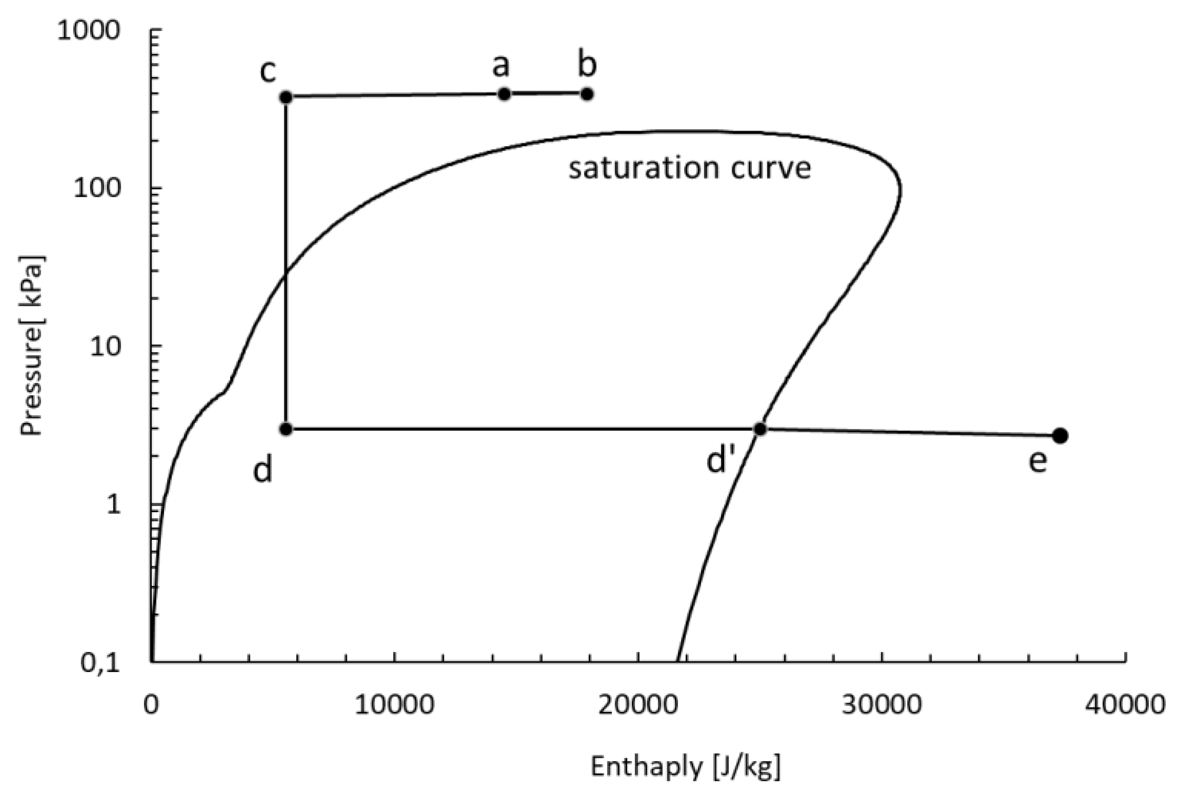
Figure 10.
Power coupler cooling method using superfluid helium.
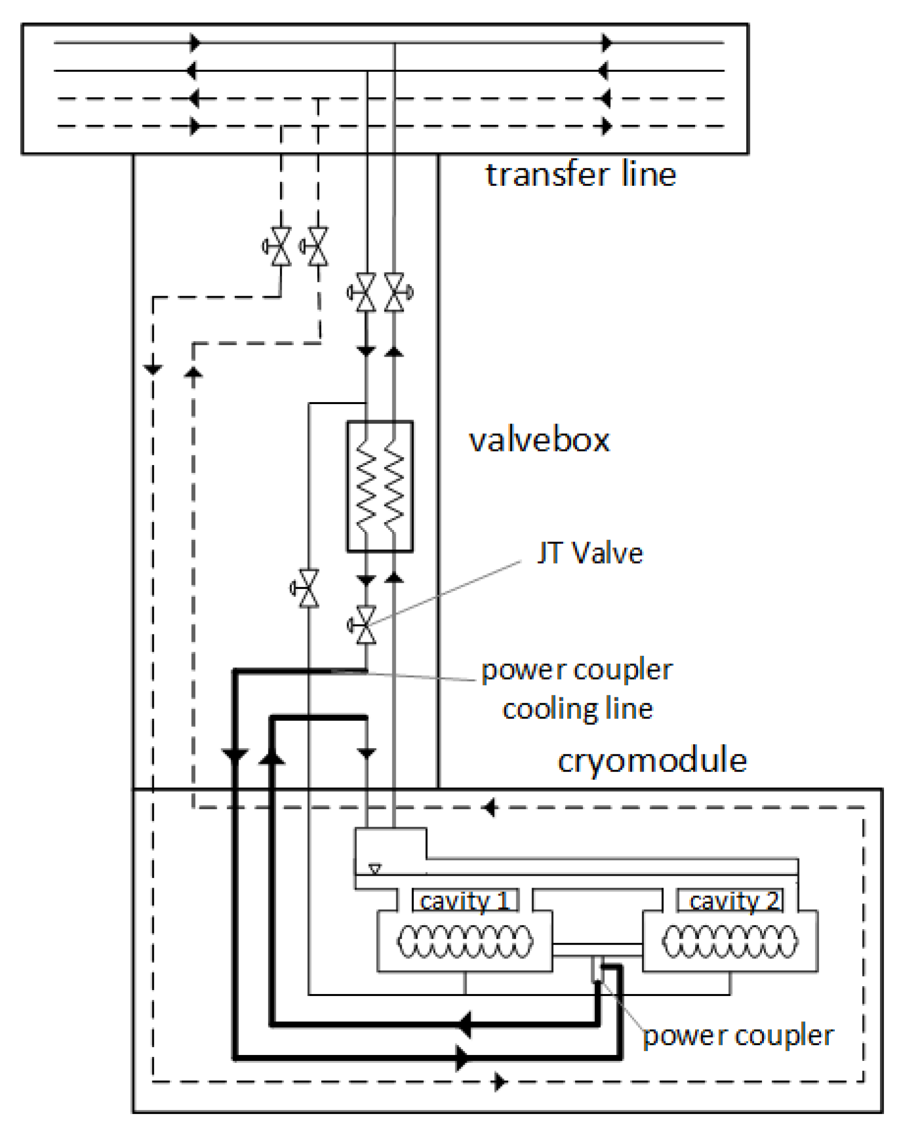
Figure 11.
Power coupler cooling method using a separated cooling loop.
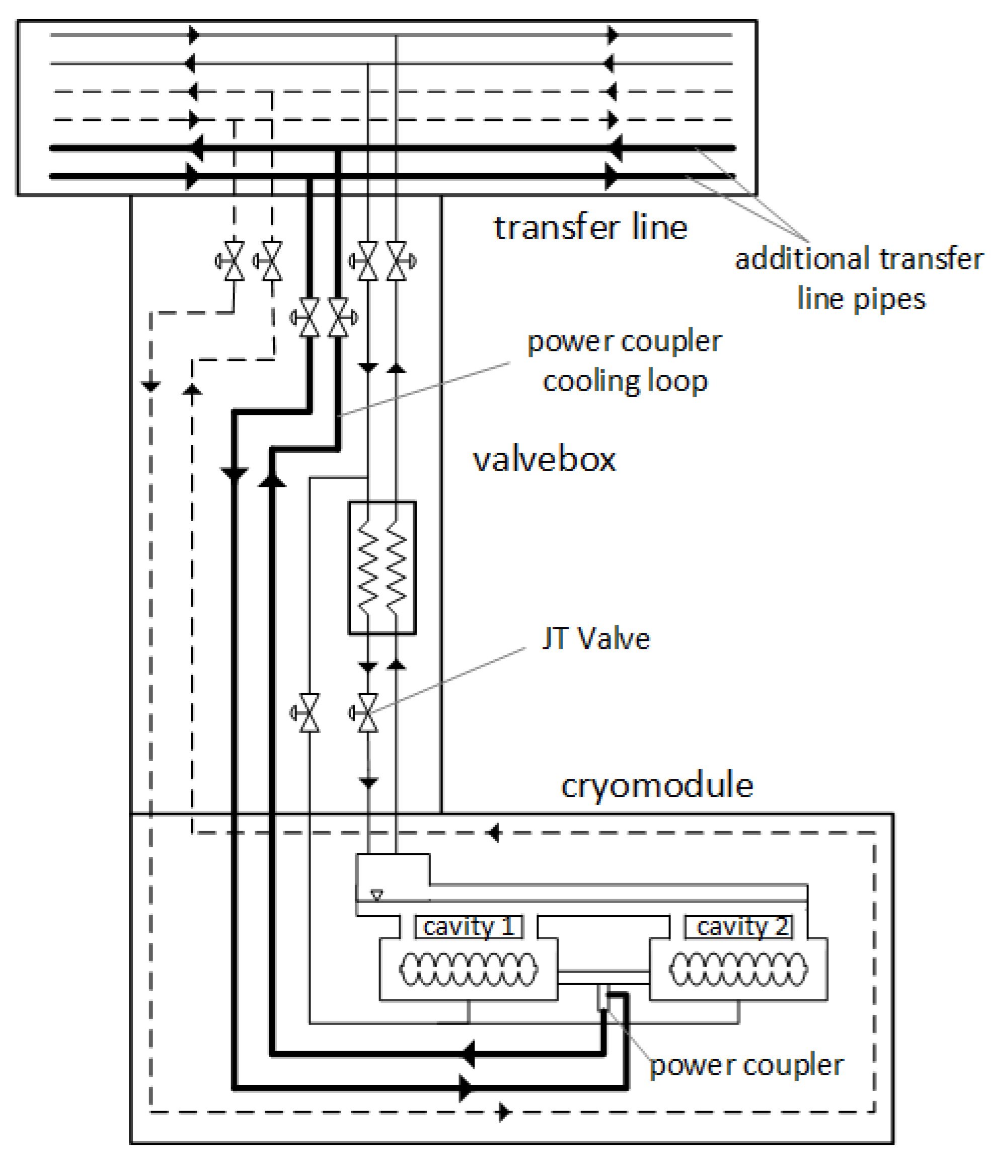
Figure 12.
Power coupler cooling method using the entire supercritical helium flux.
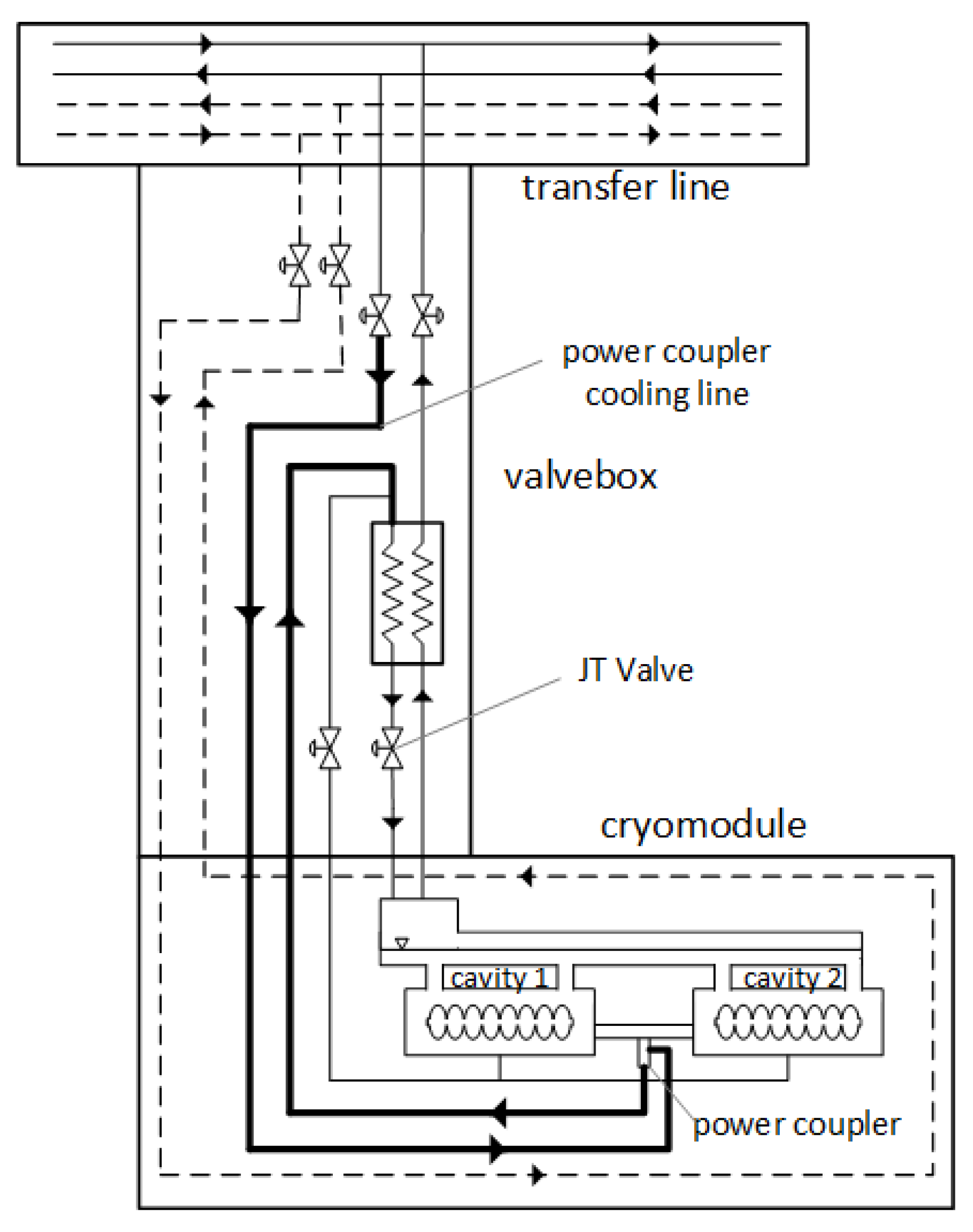
Figure 13.
Simplified schematic views of high-capacity helium croplands.
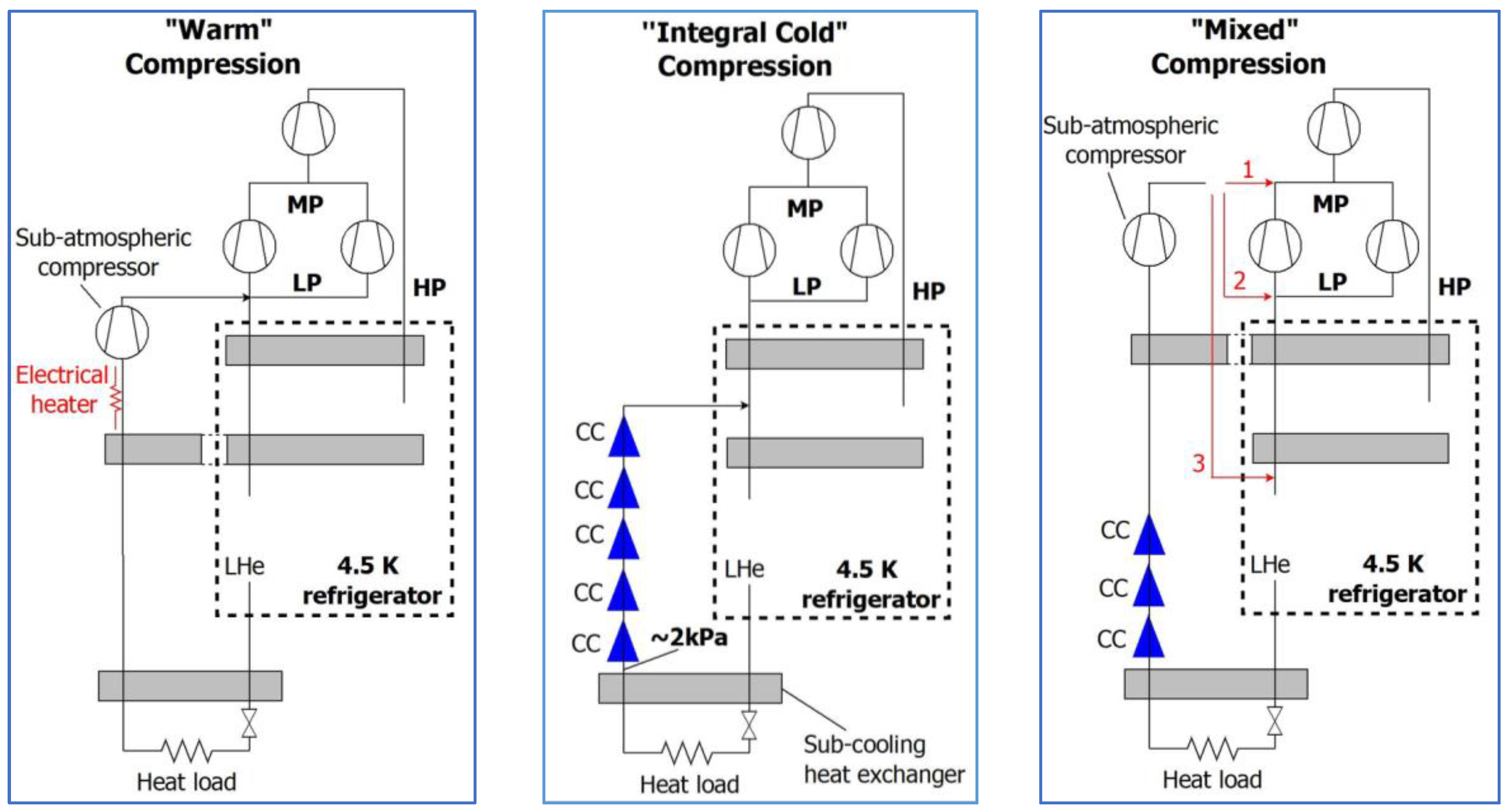
Figure 14.
The vacuum vessel and interior space of the valve box.
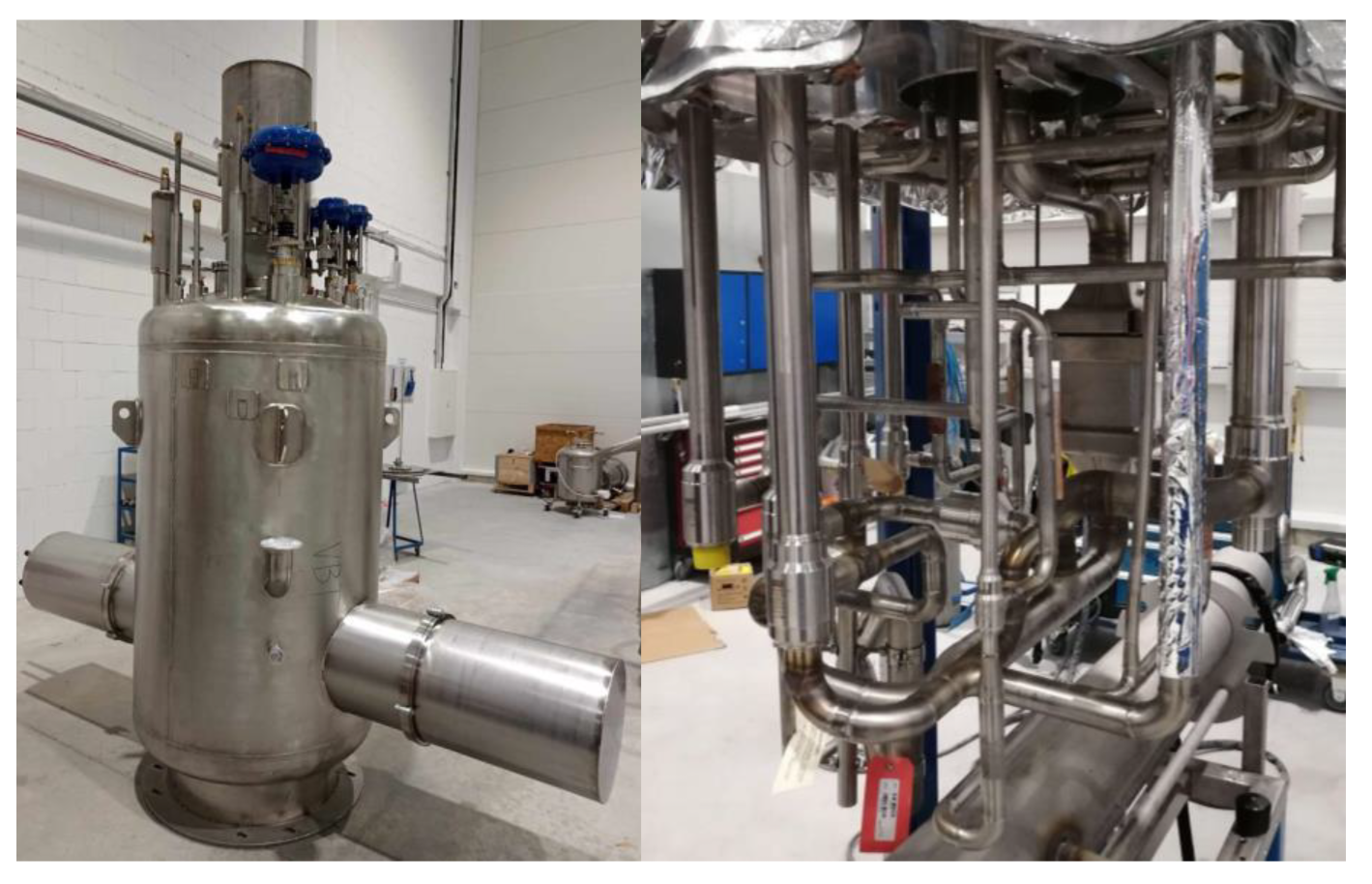

Table 1.
Entropy analysis results for the analyzed power coupler cooling design cases.
| Scenario | Transfer line | Valve box and cryomodule |
Σ | ||||
|---|---|---|---|---|---|---|---|
|
W/K |
W/K |
W/K |
W/K |
W/K |
kW |
kW |
|
| Cooling with superfluid helium generated in the valve box |
0.10 | negl. | 5.45 | - | 5.55 | 1.64 | 5.46 |
| Cooling with supercritical helium transferred in dedicated process lines |
0.58 | 0.03 | 1.73 | negl. | 2.34 | 0.69 | 2.30 |
| Cooling with supercritical helium, later used to cool the SRF cavities |
0.10 | negl. | 2.01 | negl. | 2.11 | 0.62 | 2.08 |
*PADR=PAD/0.3.
Table 2.
Entropy generation during the flow of helium in the transfer line
| Scenario | pipe size |
W/K |
W/K |
W/K |
kW |
kW |
|---|---|---|---|---|---|---|
| Cold compressors in the Cryoplant building |
DN150 | 0.77 | 0.46 | 1.23 | 0.36 | 1.03 |
| Cold compressors near the accelerator hall |
DN50 | 0.17 | 21.12 | 21.29 | 6.28 | 20.94 |
| DN80 | 0.24 | 2.52 | 2.76 | 0.82 | 2.74 | |
| DN150 | 0.46 | 0.10 | 0.56 | 0.166 | 0.55 |
Disclaimer/Publisher’s Note: The statements, opinions and data contained in all publications are solely those of the individual author(s) and contributor(s) and not of MDPI and/or the editor(s). MDPI and/or the editor(s) disclaim responsibility for any injury to people or property resulting from any ideas, methods, instructions or products referred to in the content. |
© 2025 by the authors. Licensee MDPI, Basel, Switzerland. This article is an open access article distributed under the terms and conditions of the Creative Commons Attribution (CC BY) license (http://creativecommons.org/licenses/by/4.0/).
Copyright: This open access article is published under a Creative Commons CC BY 4.0 license, which permit the free download, distribution, and reuse, provided that the author and preprint are cited in any reuse.


