Submitted:
09 May 2025
Posted:
09 May 2025
You are already at the latest version
Abstract
The goal was to asses roles of leaflets geometry on the structural deterioration of bioprosthetic aortic valves (BAVs) in closed configuration. With a Fung-type orthotropic model, finite element modeling was used to create ten cases with parabolic, circular and spline leaflet curvatures, and six leaflet angles. A circular circumferential curvature led to lower von Mises and compressive stresses in both the coaptation and load bearing areas, reduced tensile stresses in the coaptation regions, and increased tensile stresses in the load bearing areas. A parabolic radial curvature reduced von Mises stresses in the coaptation as well as load bearing regions, reduced compressive stresses in the coaptation and tensile stresses in the load bearing regions, led to a slight increase in the minimized tensile stress in the coaptation regions (1.794 vs. 1.765 MPa) and the minimized compressive stress in the load bearing regions (0.772 vs. 0.768 MPa). Within a range of downward inclination of the leaflets, all stresses in the coaptation regions decreased. A parabolic circumferential curvature, a linear radial curvature, and, for most cases, upward leaflet inclinations were associated with larger contact pressures between the leaflets. A parabolic radial curvature and downward leaflet inclination likely lead to longer durability of BAVs.
Keywords:
Bioprosthetic Aortic Valve
; Bioprosthetic Valve Durability
; Bioprosthetic Aortic valve Design
; Finite Element Analysis
1. Introduction
There is a high demand for prosthetic aortic valves. Annually 280,000 heart valve replacement (HVR) surgeries are performed worldwide27, and this number is estimated to increase three-fold in the next 35 years.41 There are two types of prosthetic heart valves, bioprosthetic or mechanical. Mechanical heart valves require lifelong anticoagulation with its associated risk of hemorrhagic complications.22,34 There are rare reports on thrombosis in BAVs (0.1-5.7% per patient-year35). As such, BAVs are preferred in comparison to mechanical heart valves. Moreover, BAVs are expected to acquire a larger portion of the market as their design is shifting toward transcatheter implantation, which significantly reduces the risks of heart valve replacement surgery.
The primary limitation of BAVs is their lifetime.49 Currently, they last for only 10-15 years46. As such, not only young patients usually are not qualified for using BAVs, but also the recommended age for prescription of BAVs is older than 60 years as recommended by American and European standards.18,26 Structural Valve Deterioration (SVD) involves non-calcification (purely mechanical) and calcification related deteriorations that initiate the failure of the leaflets.1 In non-calcification mechanisms, high mechanical stresses invade the integrity of leaflets structure, and also in calcification-related deterioration stresses within the leaflets initiate the calcification process.30,38,45 Therefore, understanding the stress distribution in the leaflets is crucial for understanding the SVD mechanisms in BAVs.
There are more than 50 heart valve designs in the market.8 These designs have distinct differences in terms of materials of the leaflets and frame, leaflet angle (the inclination of the leaflets toward the sinus), curvatures of the leaflets, the height of the valve, attachments of the leaflets to the supporting housing, etc. The importance of assessing the effects of these parameters in SVD is realized when one considers the catastrophic outcomes with faulty designs in the past. For instance, Ionescu– Shiley valve was clinically withdrawn because of the short durability of this valve caused by high mechanical stresses due to a rigid stent and a stitch-related hole near the commissure region.13,28,47,44 Similarly, Hancock pericardial xenograft was a faulty design where stitches near the commissures caused too high stresses which led to early valve failures.4,37,3 In another example, the profile of a conventional mitral porcine xenograft was designed to be short to resolve complications with the excessive protrusions of the posts to the ventricle. Consequently, the durability of the leaflets was adversely affected due to excessive mechanical stresses caused by the too short profile.14,17,44
There are studies on the effects of geometry on the mechanics of closed BHVs, which contribute to better understanding SVD of BHVs. Hamid et al. studied the effects of valve height on stresses in the leaflets.14 Lim et al. examined the effects of leaflet shape on stresses within the leaflets.20 Xiong et al. compared stenless, molded and conventional designs of prosthetic aortic valves.48 Fan et al. reported a design process for optimization of a pulmonary heart valve.10 Loerakker et al. studied the effects of geometry on the mechanics of tissue engineered heart valves.21 The effects of leaflet curvatures and angle on the mechanics and SVD of BAVs are not clear.
The goal of this study was to understand the roles of geometrical factors in SVD of BAVs, considering the closed configuration of BAVs. In particular, effects of leaflet curvatures and angle were studied using finite element modeling. Ten computational cases with different curvatures and angles were analyzed. A Fung-type orthotropic model based on biaxial test data, was used to account for the anisotropy of the leaflets. According to our knowledge, this is the first study that systematically studies the role of leaflet curvature and angle in the mechanics of BAVs in closed configuration.
2. Methods
To model different geometrical parameters ten cases are considered. Three parameters are included: the circumferential and radial curvatures, and leaflets angle. These parameters have been shown in Figure 1, and are summarized in Table 1. The commissure height was similar for all cases. SolidWorks (SolidWorks Corp, Waltham, MA, USA) was used to create the geometries which were exported to Pointwise (Pointwise Inc, Texas, USA) for meshing.7 Using structured meshes, each leaflet was discretized into 13962 elements with two layers of elements for the thickness direction. Numbers of elements were based on several computations with different mesh sizes, which assured the study was not dependent on the mesh size. The meshes were exported to ABAQUS (Simulia, Providence, USA) where finite element calculations were performed using C3D8 (continuum three-dimensional eight-node) elements.
ABAQUS standard was used for finite element calculations. Three leaflets were considered in each case. “Surface to surface general contact” was used between leaflets. The friction coefficient was 0.3.36 The load was a uniform pressure equal to 8 kPa. All displacements were set to zero at the fixed edges where leaflets were attached to the stent.
Based on a pseudoelastic assumption for pericardium12, the orthotropic Fung model in ABAQUS was used to characterize the leaflets (ABAQUS manual):
With
where and are material constants, is the elastic volume ratio, and is the deformation gradient matrix. Biaxial tensile tests were performed on a sample of pericardium to determine the material constants. The methodology of calculating material constants using biaxial tests is provided in our other report,6 and is also extensively described in the literature.15,29,36 The fibers were assumed to be mainly oriented in the circumferential and radial directions as shown in Figure 1. The material constants are summarized in Table 2.6 The constant was set to 1.0×10⁻⁷ Pa-1 for all cases to account for tissue incompressibility.
3. Results
Considering the whole valve structure, a circular circumferential curvature led to the lowest values of von Mises, tensile, and compressive stresses in comparison to a parabolic or spline curvature (Figure 2a: Case 3 vs. Cases 1&2). The coaptation areas experienced a similar reduction in stresses when a circular circumferential curvature was used (Figure 2b: Case 3 vs. Cases 1&2). For the load bearing area, a circular circumferential curvature led to the lowest von Mises and compressive stresses, but the lowest tensile stresses were obtained by a parabolic circumferential curvature (Figure 2c: Cases 3-5).
For the whole valve structure, a parabolic radial curvature led to the lowest von Mises and compressive stresses compared to a linear or circular radial curvature (Figure 2a: Case 4 vs. Cases 3&5). However, a circular radial curvature provided the lowest tensile stresses (Figure 2a: Case 4 vs. Cases 3&5). Similarly, when the coaptation areas are considered, the parabolic curvature led to lowest von Mises and compressive stresses whereas a circular curvature led to lowest tensile stress (Figure 2b: Cases 4-5). For both the whole valve structure and the coaptation regions, the tensile stresses caused by the parabolic and circular curvatures were noticeably close (1.794 vs. 1.765 MPa). Considering the load bearing areas, similar to the whole valve and coaptation regions, a parabolic curvature led to lowest von Mises stresses. The von Mises stress computed for the circular radial curvature was noticeably close to the parabolic curvature (1.147 vs. 1.13 MPa). Unlike the whole valve and the coaptation areas, the lowest tensile and compressive stresses were computed for a parabolic and a circular radial curvature, respectively. Furthermore, the compressive stresses computed for the parabolic and circular radial curvatures were noticeably close (0.772 vs. 0.768 MPa).
Considering the whole valve structure, as the leaflets inclined downward (away from the sinus), the von Mises, tensile and compressive stresses decreased (Figure 2a: Cases 3, 6-9), but when the leaflets inclined downward too far, the stresses increased (Figure 2a: Case 10). The coaptation regions showed a trend similar to the whole valve structure (Figure 2b: Cases 3, 6-10). Considering the load bearing area, a trend was not observed in terms of reduction or increase in the stresses with leaflet angle (Figure 2c: Cases 3, 6-10); however, for the valve with the highest downward inclination of the leaflet, the stresses were the highest (Figure 2c: Case 10). The peak von Mises and tensile stresses in the whole valve structure were the same peak stresses as in the coaptation regions until the leaflets inclined downward the most, at which point the peak stresses in the whole valve structure became the peak stresses in the load bearing areas (Figs. 2a&c: Case 10).
A parabolic circumferential curvature caused a higher maximum contact pressure compared to a circular or spline curvature (Figure 2d: Case 1 vs. Cases 2&3). A linear radial curvature caused a higher maximum pressure compared to a parabolic or circular radial curvature (Figure 2d: Case 3 vs. Cases 4&5). When the leaflets inclined upward (toward the sinus), the maximum contact pressure trended to increase (Figure 2d: Cases 6, 8, 9 & 10); however, not all cases followed this trend (Figure 2d: Cases 3&7).
The commissures and lower parts of the fixed edge region experienced largest stresses (Figure 3, Figure 4 and Figure 5). The commissures always experienced largest stresses regardless of the design specifications. Despite the commissure area experienced high values of tensile and compressive stresses, the directions of these stresses where different (Figure 4 and Figure 5). The contours of contact pressure were also similar for all cases (Figure 6). In all cases the adjacent leaflets were in contact (noticeable contact discontinuity was not seen).
A circular circumferential curvature provided higher displacement tip in comparison to a parabolic or spline curvature (Figure 2d: Case 3 vs. Cases 1&2). Regarding the radial curvature, a linear curvature provided the highest radial displacement compared to a parabolic or circular curvature (Figure 2d: Case 3 vs. Cases 4&5). Regarding the effects of leaflet angle on the leaflet tip displacements, as the leaflets inclined downward the radial displacements trended to decrease (Figure 2d: Cases 3, 6-10). The central gap became smaller when the radial displacement increased (Figure 2d and Figure 7).
4. Discussion
The primary limitation of BAVs is their short durability which is directly related to SVD caused by high mechanical stresses. The mechanical stresses are profoundly affected by the geometrical specifications of the valve. We assessed the effects of the geometrical parameters on SVD of BAVs, using computational modeling. Different valve design scenarios with different circumferential and linear curvatures, and leaflet angles were studied.
The effects of the circumferential curvature were not similar for the coaptation regions and the load bearing regions (Figure 2b,c, Cases 1-3). Considering the coaptation regions, a circular circumferential curvature would provide superior valve durability as a circumferential curvature provided the lowest the von Mises, first and third principal stresses (Figure 2b: Case 3 vs. Cases 1&2). The load bearing region, however, would experience higher tensile stresses if a circular circumferential curvature is used in comparison to a parabolic or spline curvature (Figure 2c: Case 3 vs. Cases 1&2).
The effects of the radial curvature were not similar for the coaptation areas and the load bearing regions (Figure 2b,c: Cases 3-5). Nonetheless, a parabolic radial curvature would be preferred as it caused lower von Mises stresses compared to a radial and circular curvature (Figure 2b,c: Case 4 vs. Cases 3&5). Although a parabolic radial curvature would cause slightly higher tensile (Figure 2b: 1.794 vs. 1.765 MPa) and compressive stresses (Figure 2c: 0.772 vs. 0.768), this effect might be practically unimportant.
The leaflet angle does not have similar effects on the coaptation and load bearing regions (Figure 2b,c). Regarding the coaptation regions, the more the leaflets are inclined downward, the lower the von Mises, the first principal and the third principal stress would be (Figure 2b: Cases3, 6-9). However, if the leaflets are highly inclined downward, the stresses might increase (Figure 2b: Case 10). The stresses in the load bearing regions did not show a straightforward reaction to the changes in leaflet angle (Figure 2c: Cases 3, 6-10). If the leaflets are highly deviated from the sinus, the load bearing areas might experience large stresses (Figure 2c: Case 10).
The load bearing as well as coaptation areas do not react to changes in leaflet curvatures and leaflets angle in the same way (Figure 2b,c). A valve design might lead to improved (lower) stresses in the commissure regions and at the same time cause higher stresses in the load bearing area. The importance of this finding becomes clearer when one notes, despite experiencing largest stresses, the commissure region might not be the most critical area as the thickness and mechanical properties might not be uniform within the leaflets.11,23,40,50 The belly might deteriorate before the commissure due to a weaker tissue in the region. Therefore, it is crucial to examine the effects of design parameters on all parts of the leaflet rather than merely the areas of highest stresses within the whole valve.
The changes in the stresses in the whole valve structure were represented by the stresses in the coaptation as well as load bearing areas (Figure 2a–c). One might make an invalid conclusion regarding the importance of geometrical parameters, if only considers the results for the whole valve structure. For instance, the importance of radial curvature on tensile stresses would not be noticeable unless the load bearing areas are separately considered (Figure 2a,c: Cases 3-5).
The stress contours were not noticeably affected by the leaflet angle or curvature. The commissure regions and the lower parts of the fixed edge region experienced large von Mises, the first principal, and the third principal stresses (Figure 3, Figure 4 and Figure 5). These locations correspond to the regions of frequent calcifications and tearing of BAVs.16,30,38 As well, the exposure of the commissure area to high stress values (Figure 3 and Figure 4) confirms previous numerical studies that calculated high stresses in this area19. It should be noted that the tensile and compressive stresses were in different directions (Figure 4 and Figure 5).
The sealing and coaptation between leaflets are crucial factors for optimal valve performance.9,23,33,42 As in all cases leaflets had full coaptation (Figure 6), the higher contact pressure would mean the leaflets provide better sealing in between them, when the valve becomes closed. Regarding the effects of circumferential curvature, a parabolic curvature provided better sealing between adjacent leaflets, compared to a circular or spline curvature (Figure 2d: Case 1 vs. Cases 2&3). Regarding the radial curvature, a linear radial curvature provided a better sealing between adjacent leaflets, compared to a parabolic or circular curvature (Figure 2d: Case 3 vs. Cases 4&5). Most likely, there is a trend regarding the effects of leaflets inclination on the sealing between adjacent leaflets: the more the leaflets are inclined upward, the better the sealing between adjacent leaflets would be (Figure 2d: Cases 6, 8-10); however, this trend might not be valid (Cases 3&7).
A circular circumferential curvature would provide lower chances of regurgitation at the central gap when the leaflet is closed (Figure 2d and Figure 7: Case 3 vs. Cases 1&2, Figure 7: Case 3). A radial curvature would provide stronger central gap closure compared to a parabolic or circular curvature (Figure 2d and Figure 7: Case 3 vs. Cases 4&5). The more the leaflets are inclined upward, the lower the chances of regurgitations at the central gap would become (Figure 2d and Figure 7: Case 3, 6-10). It should be noted that leaflets might wrinkle and pinwheel if too strong contacts happen between leaflets in the central area43.
Mercer et al. measured the dimensions of the load bearing part of human aortic valve and concluded that they have a parabolic curvature in circumferential and radial directions25. Our results confirm the results obtained by Mercer et al. in that a parabola is the optimized radial curvature for the leaflets (Figure 2c: Case 3 vs. Cases 4&5). However, according to our results, although the maximum tensile stresses would be lower by a parabolic circumferential curvature, the von Mises and the compressive stresses would be higher for a parabolic curvature compared to a spline or circular curvature (Figure 2c: Case 1 vs. Cases 2&3). Considering the results in our study and those by Mercer et al., it might be concluded that the circumferential curvature of the load bearing part of the native aortic valve is optimized to have minimum tensile stresses (and not von Mises and compressive stresses). However, it should be noted that in the native vale the leaflets function as one of the components of the aortic root assembly during whole cardiac cycle. The mechanics of the native valve is in harmony with the aortic root, which could affect the optimum valve geometry.5,32,39 The optimum curvature of the native valve is not merely determined by the leaflets geometry but also its dynamic motions in synchrony with the aortic root.
We studied the effects of geometrical parameters on mechanics of BAVs when a uniform pressure load was applied on the leaflets. In reality, the load on the leaflets is not a simple uniform pressure load, but a resultant from the complex interaction between blood flow and leaflets. However, this limitation is not thought to revoke the findings of our study as far as the comparative importance of geometrical factors is considered. Furthermore, we studied the closed valve where the leaflet displacements are not as large as when the valve opens and closes. The blood pressure would more noticeably be affected by the leaflets motions when leaflet open and close. Since our goal was to compare different valve designs, the lower end of diastolic pressure (8 kPa) was used, which is computationally more efficient.
We used a nonlinear Fung type constitutive equation for the leaflets. The constants of the Fung model were based on biaxial test data for only one sample. The constants would likely change if more samples were used in the biaxial tests. However, the objective of the study was not affected by this limitation, as the same constants were used in all case studies.
The fiber orientations directly affect material properties of the leaflets. Based on experimental data for porcine aortic valve leaflets,2,23,31 we assumed the fibers are oriented in two main directions (Figure 1). In reality, the mapping of fibers within the leaflets of BAVs might be basically different from our assumption. This limitation is not thought to notably affect the results of this study, as fiber orientations were similar for all cases. If a study aims to particularly examine the contours and values of stresses for a specific valve design, the orientations of the fibers throughout the leaflet needs to be based on more precise measurements about the fiber orientations.
The results of this study should be interpreted with caution. This investigation presented the importance of geometrical parameters when the valve is closed. When the valve opens and closes, the effects of geometrical parameters might not be similar to a closed valve configuration. We recently showed that during systole, the von Mises stress reduces when the leaflets incline upward, which is not similar to the effects of leaflet inclination for a closed valve.7 It is therefore crucial to consider both the systole and diastole (whole cardiac cycle) when studying the mechanics of BAVs.
We studied the effects of geometrical parameters on the mechanics of BAVs, when the valve is closed. Different leaflet circumferential and radial curvatures as well as the angle of the leaflet where examined by ten case studies. Results showed that the load bearing area and the coaptation regions might not react similarly when the leaflets geometrical parameters are altered. Considering the mechanics of closed BAVs, the chances of SVD would be less if leaflets have a parabolic radial curvature and are inclined more downward within a range. These results could contribute to better understand the mechanisms of SVD in BAVs, and lead to better BAVs durability.
Conflicts of Interest
None.
References
- Akins, C.W.; Miller, D.C.; Turina, M.I.; Kouchoukos, N.T.; Blackstone, E.H.; Grunkemeier, G.L.; Takkenberg, J.J.; David, T.E.; Butchart, E.G.; Adams, D.H.; et al. Councils of the American Association for Thoracic Surgery; Society of Thoracic Surgeons; European Assoication for Cardio-Thoracic Surgery; Ad Hoc Liaison Committee for Standardizing Definitions of Prosthetic Heart Valve Morbidity. Guidelines for reporting mortality and morbidity after cardiac valve interventions. J Thorac Cardiovasc Surg. 2008, 135, 732–738. [Google Scholar] [PubMed]
- Billiar, K.L.; Sacks, M.S. Biaxial mechanical properties of the natural and glutaraldehyde treated aortic valve cusp--Part I: Experimental results. J Biomech Eng. 2000, 122, 23–30. [Google Scholar] [CrossRef] [PubMed]
- Bortolotti, U.; Milano, A.; Guerra, F.; Mazzucco, A.; Mossuto, E.; Thiene, G.; Gallucci, V. Failure of Hancock pericardial xenografts: is prophylactic bioprosthetic replacement justified? Ann Thorac Surg. 1991, 5, 430–437. [Google Scholar] [CrossRef]
- Bortolotti, U.; Milano, A.; Thiene, G.; Guerra, F.; Mazzucco, A.; Valente, M.; Talenti, E.; Gallucci, V. Early mechanical failures of the Hancock pericardial xenograft. J Thorac Cardiovasc Surg. 1987, 94, 200–207. [Google Scholar] [CrossRef] [PubMed]
- Brewer, R.J.; Deck, J.D.; Capati, B.; Nolan, S.P. The dynamic aortic root. Its role in aortic valve function. J Thorac Cardiovasc Surg. 1976, 72, 413–417. [Google Scholar] [CrossRef]
- Dabiri, Y.; Paulson, K.; Tyberg, J.; Ronsky, J.; Ali, I.; E. Di Martino, Narine, K. Design of Bioprosthetic Aortic Valves using biaxial test data. Proceedings of IEEE Eng Med Biol Soc. 2015, 2015, 3319–3322.
- Dabiri, Y.; Ronsky, J.; Ali, I.; Basha, A.; Bhanji, A.; Narine, K. Effects of Leaflet Design on Transvalvular Gradients of Bioprosthetic Heart Valves, Cardiovasc Eng Technol. 2016, In Press. [CrossRef]
- Dasi, L.P.; Simon, H.A.; Sucosky, P.; Yoganathan, A.P. Fluid mechanics of artificial heart valves. Clin Exp Pharmacol Physiol. 2009, 36, 225–237. [Google Scholar] [CrossRef]
- Duraiswamy, N.; Weaver, J.D.; Ekrami, Y.; Retta, S.M.; Wu, C. A Parametric Computational Study of the Impact of Non-circular Configurations on Bioprosthetic Heart Valve Leaflet Deformations and Stresses: Possible Implications for Transcatheter Heart Valves. Cardiovasc Eng Technol. 2016, 7, 126–138. [Google Scholar] [CrossRef]
- Fan, R.; Bayoumi, A.S.; Chen, P.; Hobson, C.M.; Wagner, W.R.; J.E. Mayer Jr., Sacks, M.S. Optimal elastomeric scaffold leaflet shape for pulmonary heart valve leaflet replacement. J Biomech. 2013, 46, 662–669. [CrossRef]
- Fleisher, A.G.; Lafaro, R.J.; Moggio, R.A. Immediate structural valve deterioration of 27-mm Carpentier-Edwards aortic pericardial bioprosthesis. Ann Thorac Surg. 2004, 77, 1443–1445. [Google Scholar] [CrossRef]
- Fung, Y.C. Biomechanics: Mechanical Properties of Living Tissues. NewYork: Springer Verlag, 1993.
- Gabbay, S.; Bortolotti, U.; Wasserman, F.; Tindel, N.; Factor, S.M.; Frater, R.W. Long-term follow-up of the Ionescu-Shiley mitral pericardial xenograft. J Thorac Cardiovasc Surg. 1984, 88, 758–763. [Google Scholar] [CrossRef] [PubMed]
- Hamid, M.S.; Sabbah, H.N.; Stein, P.D. Influence of stent height upon stresses on the cusps of closed bioprosthetic valves. J Biomech. 1986, 19, 759–769. [Google Scholar] [CrossRef] [PubMed]
- Humphrey, J.D.; Strumpf, R.K.; Yin, F.C. A constitutive theory for biomembranes: application to epicardial mechanics. J Biomech Eng. 1992, 114, 461–466. [Google Scholar] [CrossRef] [PubMed]
- Ishihara, T.; Ferrans, V.J.; Boyce, S.W.; Jones, M.; Roberts, W.C. Structure and classification of cuspal tears and perforations in porcine bioprosthetic cardiac valves implanted in patients. Am J Cardiol. 1981, 48, 665–678. [Google Scholar] [CrossRef]
- Ius, P.; Thiene, G.; Minarini, M.; Valente, M.; Bortolotti, U.; Talenti, E.; Casarotto, D. Low-profile porcine bioprosthesis (Liotta): pathologic findings and mode of failure in the long-term. J Heart Valve Dis. 1996, 5, 323–327. [Google Scholar]
- Joint Task Force on the Management of Valvular Heart Disease of the European Society of Cardiology (ESC); European Association for Cardio-Thoracic Surgery (EACTS), Vahanian, A.; Alfieri, O.; Andreotti, F.; Antunes, M.J.; G. Barón-Esquivias, Baumgartner, H.; Borger, M.A.; Carrel, T.P.; M. De Bonis, Evangelista, A.; Falk, V.; Iung, B.; Lancellotti, P.; Pierard, L.; Price, S.; Schäfers, H.J.; Schuler, G.; Stepinska, J.; Swedberg, K.; Takkenberg, J.; U.O. Von Oppell, Windecker, S.; Zamorano, J.L.; Zembala, M. Guidelines on the management of valvular heart disease (version 2012). 2012, 33, 2451–2496.
- Krucinski, S.; Vesely, I.; Dokainish, M.A.; Campbell, G. Numerical simulation of leaflet flexure in bioprosthetic valves mounted on rigid and expansile stents. J Biomech. 1993, 26, 929–943. [Google Scholar] [CrossRef]
- Lim, K.H.; Candra, J.; Yeo, J.H.; Duran, C.M. Flat or curved pericardial aortic valve cusps: a finite element study. J Heart Valve Dis. 2004, 13, 792–797. [Google Scholar]
- Loerakker, S.; Argento, G.; Oomens, C.W.; Baaijens, F.P. Effects of valve geometry and tissue anisotropy on the radial stretch and coaptation area of tissue-engineered heart valves. J Biomech. 2013, 46, 1792–1800. [Google Scholar] [CrossRef]
- Manning, K.B.; Herbertson, L.H.; Fontaine, A.A.; Deutsch, S. A detailed fluid mechanics study of tilting disk mechanical heart valve closure and the implications to blood damage. J Biomech Eng. 2008, 130, 041001. [Google Scholar] [CrossRef]
- Martin, C.; Sun, W. Simulation of long-term fatigue damage in bioprosthetic heart valves: effects of leaflet and stent elastic properties. Biomech Model Mechanobiol. 2014, 13, 759–770. [Google Scholar] [CrossRef] [PubMed]
- Martin, C.; Sun, W. Biomechanical characterization of aortic valve tissue in humans and common animal models. J Biomed Mater Res A. 2012, 100, 1591–1599. [Google Scholar] [CrossRef] [PubMed]
- Mercer, J.L.; Benedicty, M.; Bahnson, H.T. The geometry and construction of the aortic leaflet. J Thorac Cardiovasc Surg. 1973, 65, 511–518. [Google Scholar] [CrossRef] [PubMed]
- Nishimura, R.A.; Otto, C.M.; Bonow, R.O.; Carabello, B.A.; J.P. Erwin III, Guyton, R.A.; P.T. O’Gara, Ruiz, C.E.; Skubas, N.J.; Sorajja, P.; T.M. Sundt III, Thomas, J.D. 2014 AHA/ACC guideline for the management of patients with valvular heart disease: a report of the American College of Cardiology/American Heart Association Task Force on Practice Guidelines. J Am Coll Cardiol. 2014, 63, e57–185. [CrossRef]
- Pibarot, P.; Dumesnil, J.G. Prosthetic heart valves: selection of the optimal prosthesis and long-term management. Circulation. 2009, 119, 1034–1048. [Google Scholar] [CrossRef]
- Reul , G.J., Jr.; Cooley, D.A.; Duncan, J.M.; Frazier, O.H.; Hallman, G.L.; Livesay, J.J.; Ott, D.A.; Walker, W.E. Valve failure with the Ionescu-Shiley bovine pericardial bioprosthesis: analysis of 2680 patients. J Vasc Surg. 1985, 2, 192–204. [Google Scholar] [CrossRef]
- Sacks, M.S.; Chuong, C.J. Orthotropic mechanical properties of chemically treated bovine pericardium. Ann Biomed Eng. 1998, 26, 892–902. [Google Scholar] [CrossRef]
- Sacks, M.S.; Schoen, F.J. Collagen fiber disruption occurs independent of calcification in clinically explanted bioprosthetic heart valves. J Biomed Mater Res. 2002, 62, 359–371. [Google Scholar] [CrossRef]
- Sacks, M.S.; Smith, D.B.; Hiester, E.D. A small angle light scattering device for planar connective tissue microstructural analysis. Ann Biomed Eng. 1997, 25, 678–689. [Google Scholar] [CrossRef]
- Sacks, M.S.; Yoganathan, A.P. Heart valve function: a biomechanical perspective. Philos Trans R Soc Lond B Biol Sci. 2007, 362, 1369–1391. [Google Scholar] [CrossRef]
- Scharfschwerdt, M.; R. Meyer-Saraei, Schmidtke, C.; Sievers, H.H. Hemodynamics of the Edwards Sapien XT transcatheter heart valve in noncircular aortic annuli. J Thorac Cardiovasc Surg. 2014, 148, 126–132. [CrossRef]
- Schoen, F.J. Heart valve tissue engineering: quo vadis? Curr Opin Biotechnol. 2011, 22, 698–705. [Google Scholar] [CrossRef] [PubMed]
- Siddiqui, R.F.; Abraham, J.R.; Butany, J. Bioprosthetic heart valves: modes of failure. Histopathology. 2009, 55, 135–144. [Google Scholar] [CrossRef]
- Sun, W.; Sacks, M.S. Finite element implementation of a generalized Fung-elastic constitutive model for planar soft tissues. Biomech Model Mechanobiol. 2005, 4, 190–199. [Google Scholar] [CrossRef]
- Thiene, G.; Bortolotti, U.; Valente, M.; Milano, A.; Calabrese, F.; Talenti, E.; Mazzucco, A.; Gallucci, V. Mode of failure of the Hancock pericardial valve xenograft. Am J Cardiol. 1989, 63, 129–133. [Google Scholar] [CrossRef]
- Thubrikar, M.J.; Deck, J.D.; Aouad, J.; Nolan, S.P. Role of mechanical stress in calcification of aortic bioprosthetic valves. J Thorac Cardiovasc Surg. 1983, 86, 115–125. [Google Scholar] [CrossRef] [PubMed]
- Thubrikar, M.; Harry, R.; Nolan, S.P. Normal aortic valve function in dogs. Am J Cardiol. 1977, 40, 563–568. [Google Scholar] [CrossRef]
- Trowbridge, E.A.; Crofts, C.E. Pericardial heterograft valves: an assessment of leaflet stresses and their implications for heart valve design. J Biomed Eng. 1987, 9, 345–355. [Google Scholar] [CrossRef]
- Yacoub, M.H.; Takkenberg, J.J. Will heart valve tissue engineering change the world? Nat Clin Pract Cardiovasc Med. 2005, 2, 60–61. [Google Scholar] [CrossRef]
- Young, E.; Chen, J.F.; Dong, O.; Gao, S.; Massiello, A.; Fukamachi, K. Transcatheter heart valve with variable geometric configuration: in vitro evaluation. Artif Organs. 2011, 35, 1151–1159. [Google Scholar] [CrossRef]
- Vesely, I. Transcatheter valves: a brave New World. J Heart Valve Dis. 2010, 19, 543–558. [Google Scholar] [PubMed]
- Vesely, I. The evolution of bioprosthetic heart valve design and its impact on durability. Cardiovasc Pathol. 2003, 12, 277–286. [Google Scholar] [CrossRef] [PubMed]
- Vesely, I.; Boughner, D.; Song, T. Tissue buckling as a mechanism of bioprosthetic valve failure. Ann Thorac Surg. 1988, 46, 302–308. [Google Scholar] [CrossRef] [PubMed]
- Vongpatanasin, W.; Hillis, L.D.; Lange, R.A. Prosthetic heart valves. N Engl J Med. 1996, 335, 407–416. [Google Scholar] [CrossRef]
- Walley, V.M.; Keon, W.J. Patterns of failure in Ionescu-Shiley bovine pericardial bioprosthetic valves. J Thorac Cardiovasc Surg. 1987, 93, 925–933. [Google Scholar] [CrossRef]
- Xiong, F.L.; Goetz, W.A.; Chong, C.K.; Chua, Y.L.; Pfeifer, S.; Wintermantel, E.; Yeo, J.H. Finite element investigation of stentless pericardial aortic valves: relevance of leaflet geometry. Ann Biomed Eng. 2010, 38, 1908–1918. [Google Scholar] [CrossRef]
- Zhao, D.F.; Seco, M.; Wu, J.J.; Edelman, J.B.; Wilson, M.K.; Vallely, M.P.; Byrom, M.J.; Bannon, P.G. Mechanical Versus Bioprosthetic Aortic Valve Replacement in Middle-Aged Adults: A Systematic Review and Meta-Analysis.2016, 102, 315–327. [CrossRef]
- Zioupos, P.; Barbenel, J.C.; Fisher, J. Anisotropic Elasticity and Strength of Glutaraldehyde Fixed Bovine Pericardium for Use in Pericardial Bioprosthetic Valves, J Biomed Mater Res. 1994, 28, 49–57. [CrossRef]
Figure 1.
The radial and circumferential curvature, leaflet height and angle are shown. The main fiber orientations are shown by arrows 1 and 2. The leaflet height and the commissure height were the same for all cases. Circumferential and radial curvatures as well as the leaflet angle were altered by creating ten case studies (Table 1).
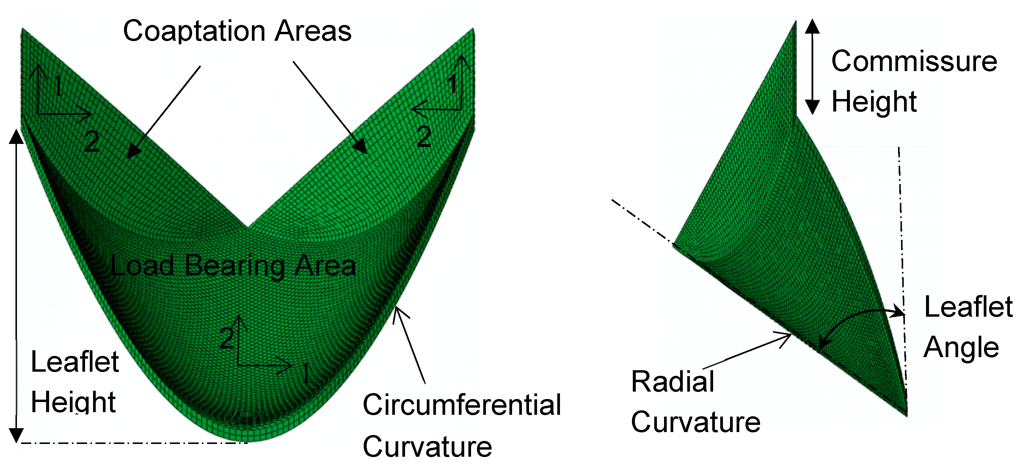
Figure 2.
The highest value of (a) stresses (MPa) for the whole valve structure, (b) stresses (MPa) for all six coaptation areas, (c) stresses (MPa) for all three load bearing areas, (d) the contact pressure (MPa) and the radial displacement (mm) of the tip of one leaflet. The values of third principal stress have been multiplied by -1.
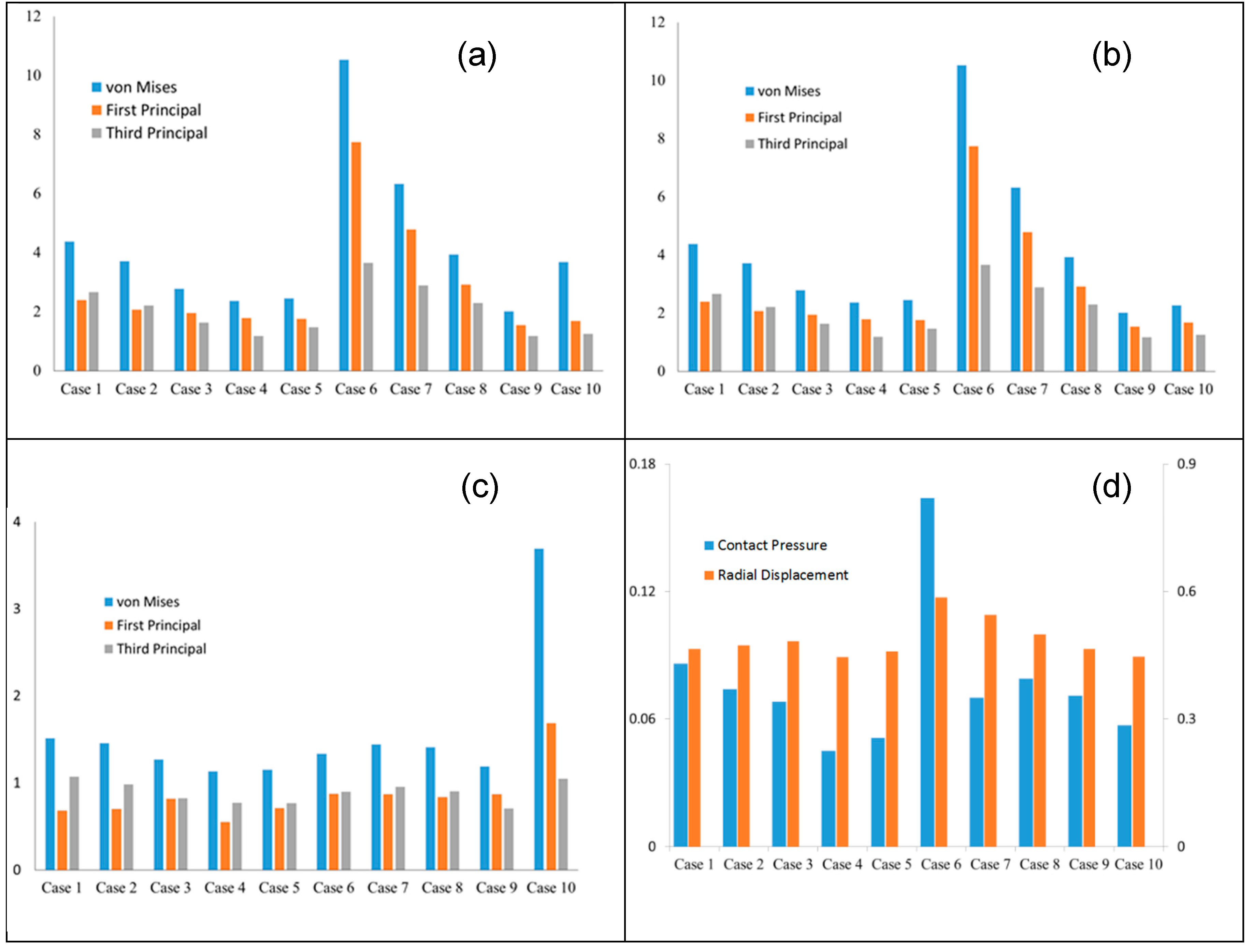
Figure 3.
The von Mises stress (MPa) contours were similar for all cases. The commissures and lower parts of the fixed edge regions experienced largest stresses.
Figure 3.
The von Mises stress (MPa) contours were similar for all cases. The commissures and lower parts of the fixed edge regions experienced largest stresses.
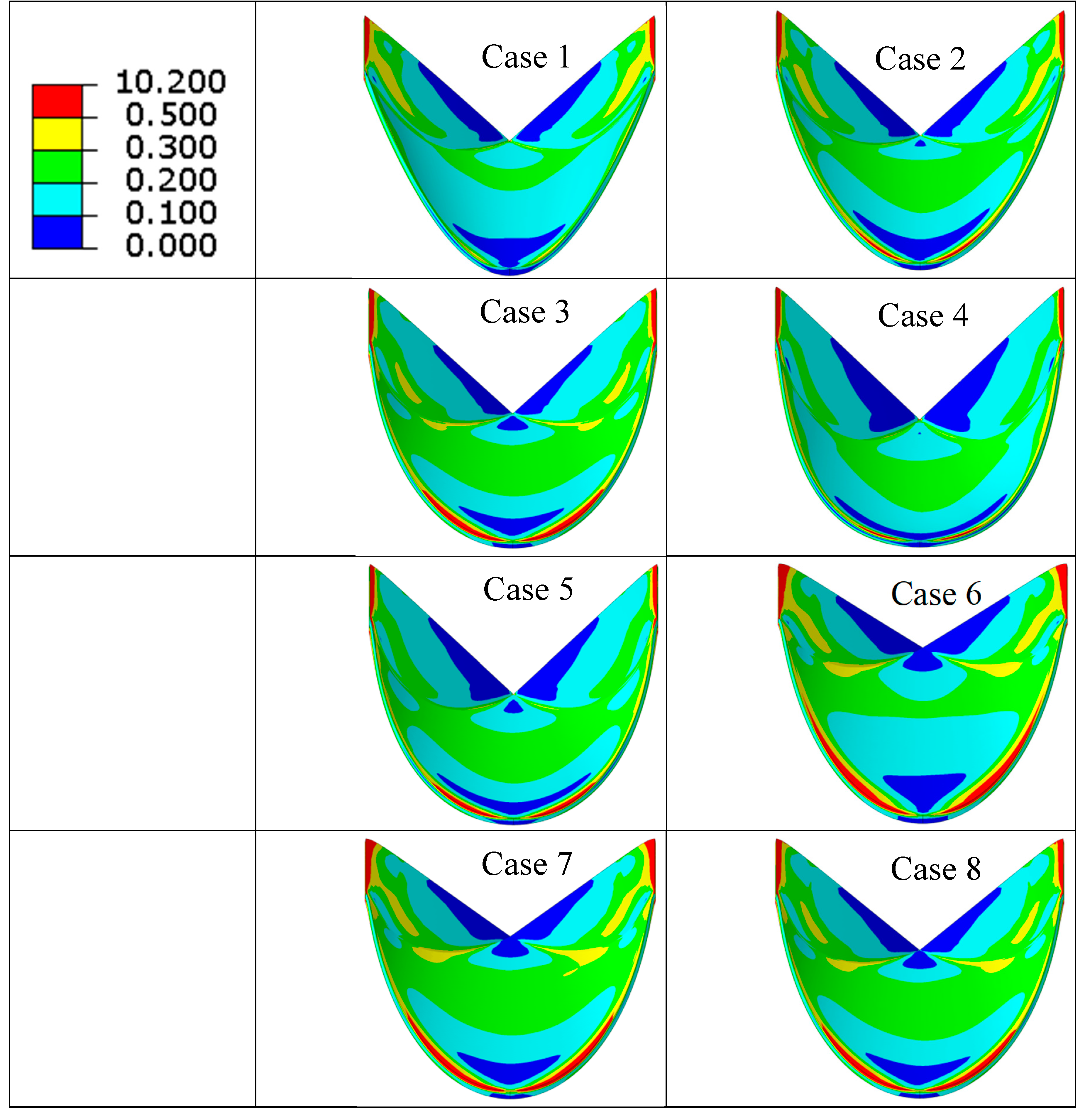
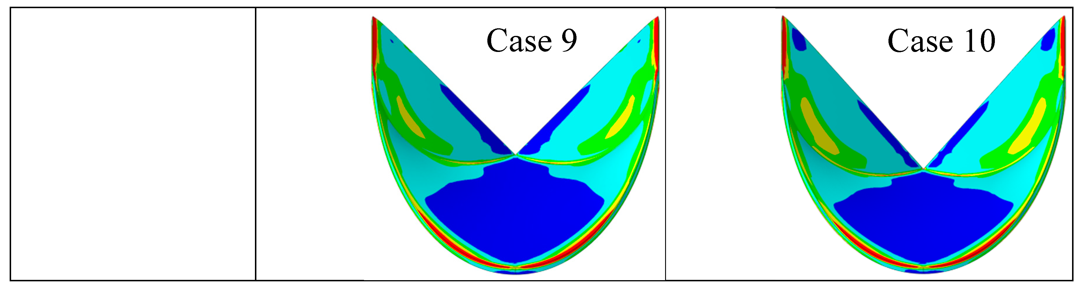
Figure 4.
The first principal stress (MPa) contours were similar for all cases. The commissures and lower parts of the fixed edge regions experienced largest stresses. The direction of the first principal stresses for Case 1 is shown, but other cases had similar directions.
Figure 4.
The first principal stress (MPa) contours were similar for all cases. The commissures and lower parts of the fixed edge regions experienced largest stresses. The direction of the first principal stresses for Case 1 is shown, but other cases had similar directions.
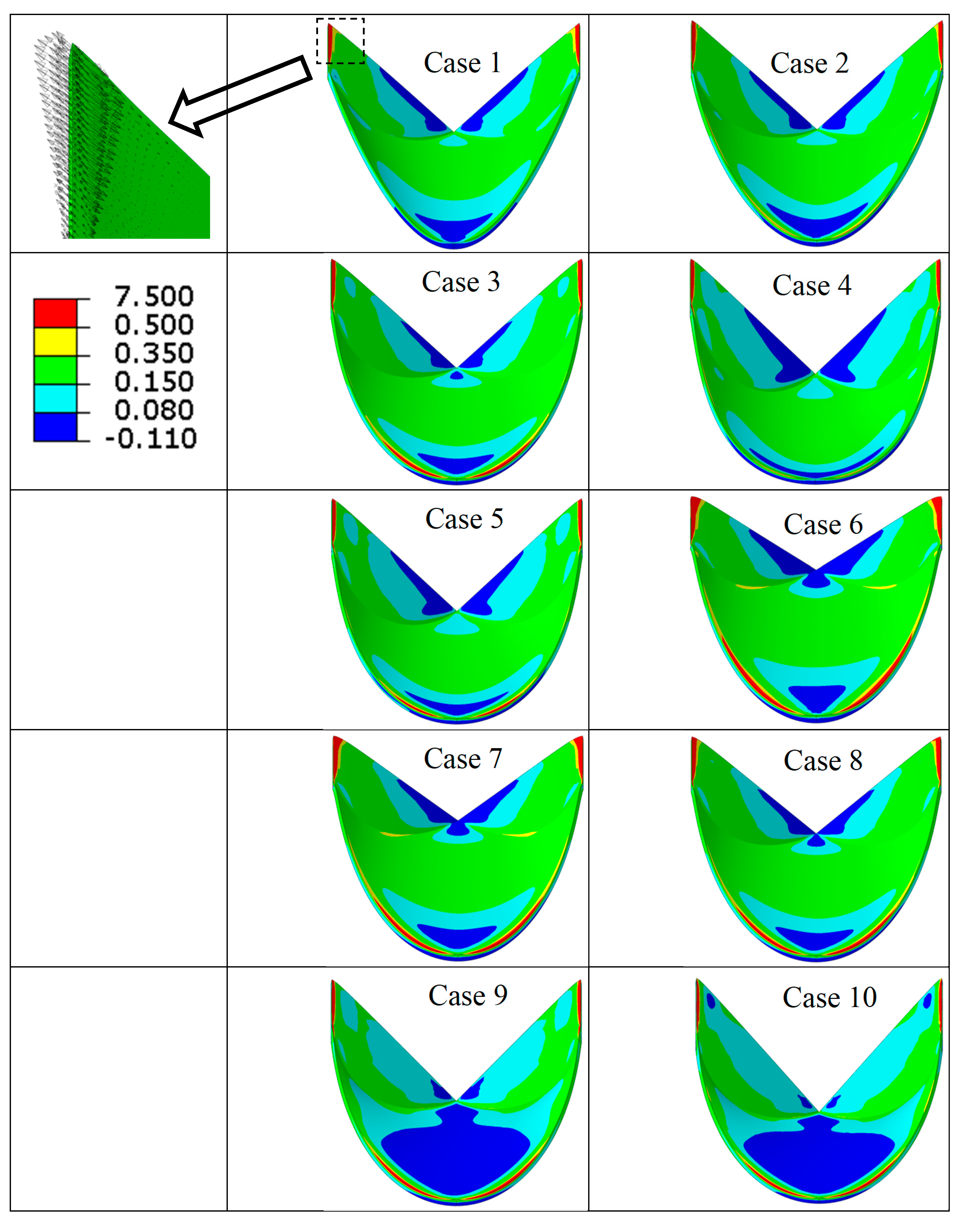
Figure 5.
The third principal stress (MPa) contours were similar for all cases. The commissures and lower parts of the fixed edge regions experienced largest stresses. The direction of the third principal stresses for Case 1 is shown, but other cases had similar directions.
Figure 5.
The third principal stress (MPa) contours were similar for all cases. The commissures and lower parts of the fixed edge regions experienced largest stresses. The direction of the third principal stresses for Case 1 is shown, but other cases had similar directions.
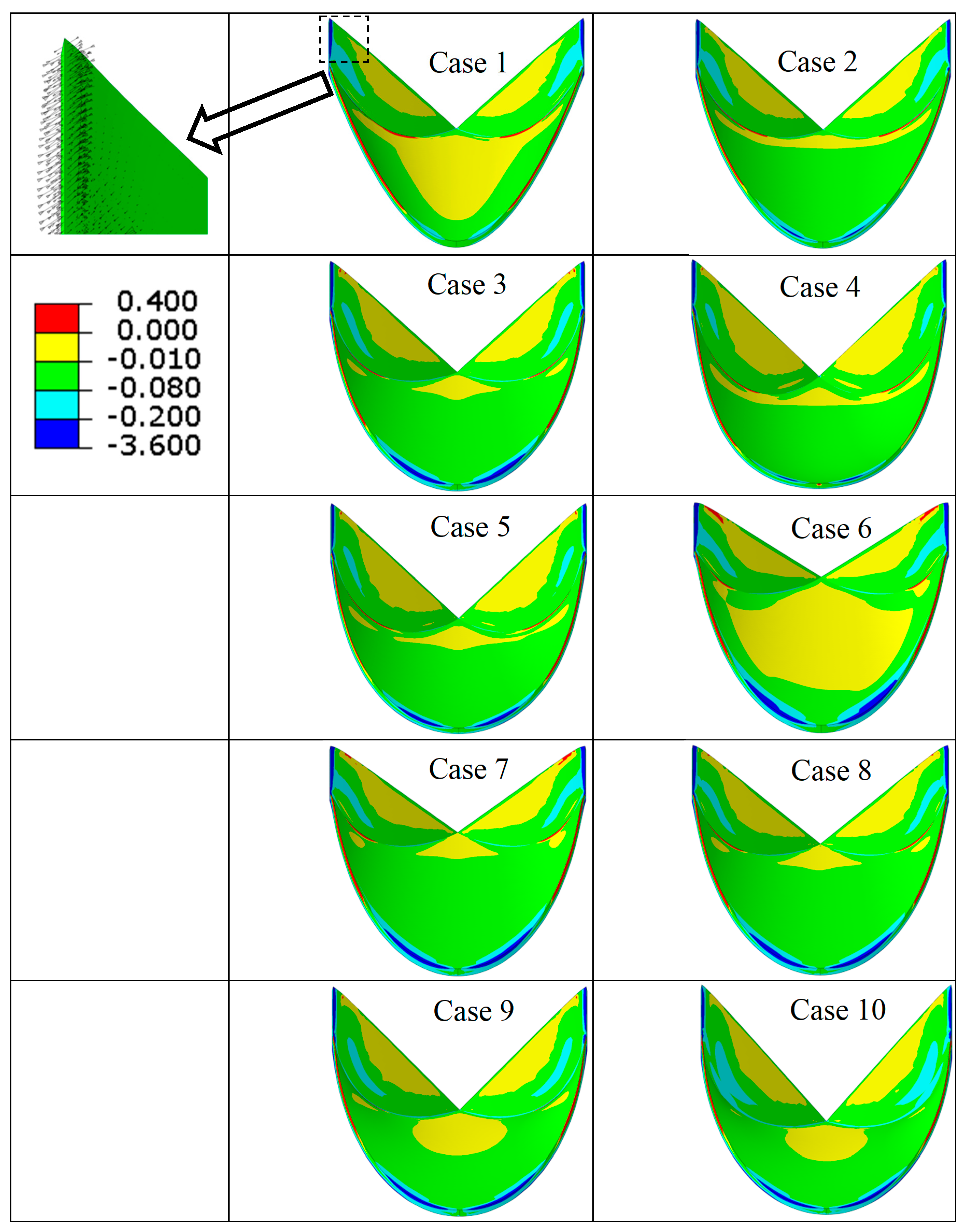
Figure 6.
The contact pressures (MPa) contours were similar for all cases. There were not major discontinuities in the contact between leaflets. The free edge of the leaflets experienced largest values of contact pressure.
Figure 6.
The contact pressures (MPa) contours were similar for all cases. There were not major discontinuities in the contact between leaflets. The free edge of the leaflets experienced largest values of contact pressure.
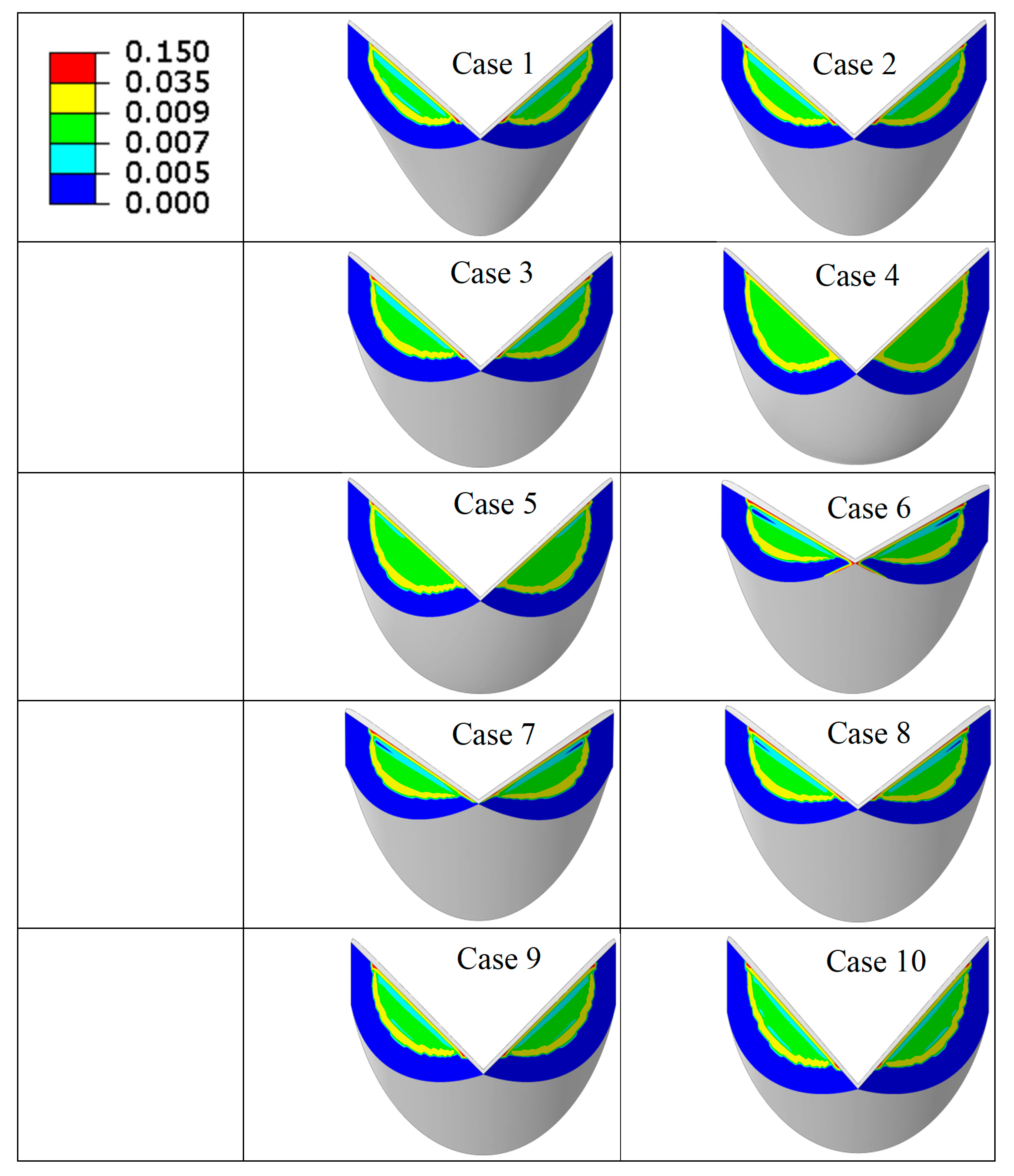
Figure 7.
The closed valve for all case studies. The central gap, shown by an arrow, was affected by geometrical parameters.
Figure 7.
The closed valve for all case studies. The central gap, shown by an arrow, was affected by geometrical parameters.
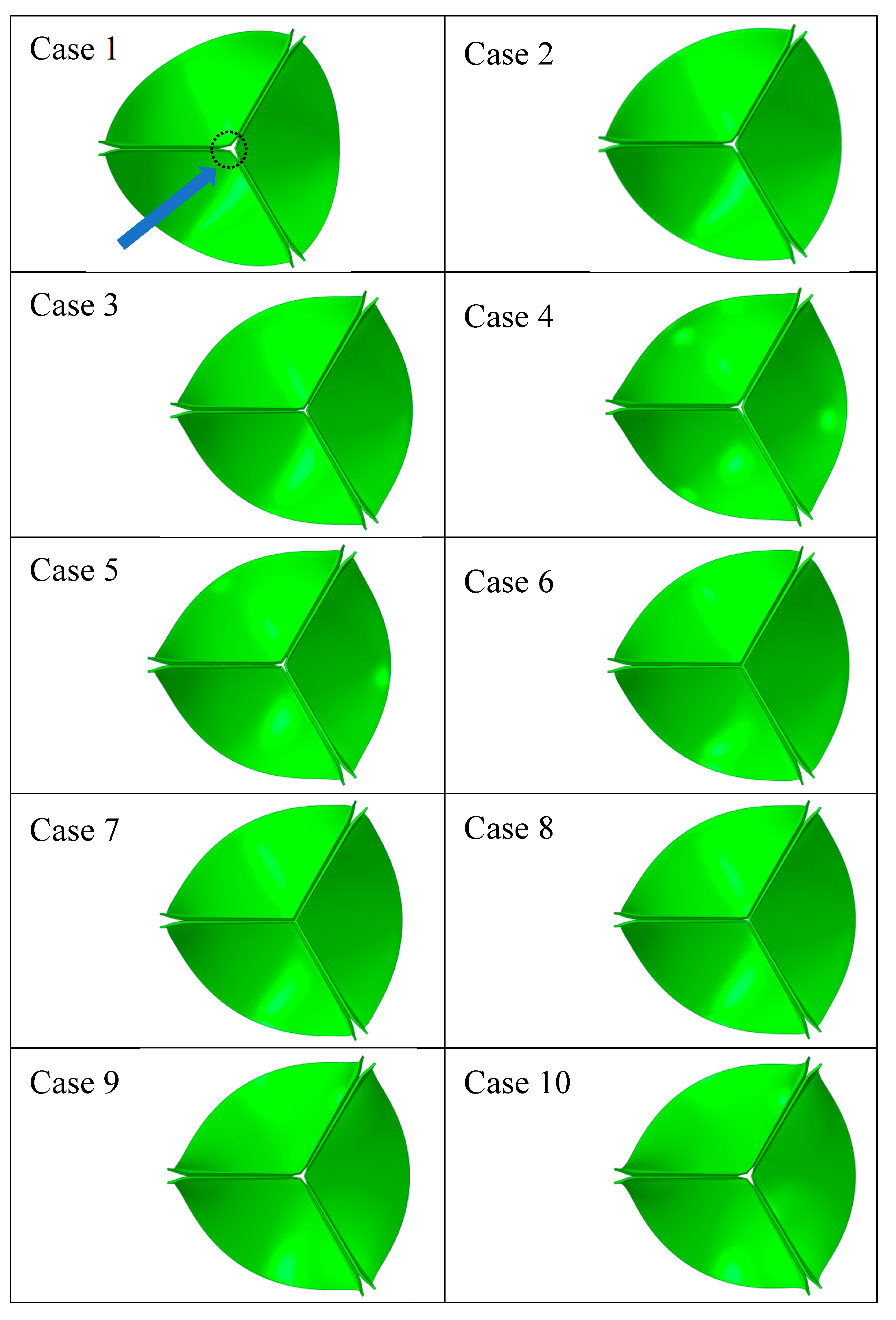

Table 1.
Ten cases were considered with the geometrical parameters specified below. The radial and circumferential curvatures are for the load bearing part of the leaflets. The coaptation height was the same for all cases. The cases were used to study the effects of circumferential curvature (1-3), radial curvature (3-5), and leaflet angle (3, 6-10).
| Case number | Leaflet angle (degree) | Radial Curvature | Circumferential Curvature |
|---|---|---|---|
| 1 | 54.4 | linear | Parabola |
| 2 | 54.4 | Linear | Spline |
| 3 | 54.4 | Linear | Circular |
| 4 | - | Parabola | Circular |
| 5 | - | Circular | Circular |
| 6 | 45.0 | Linear | Circular |
| 7 | 47.85 | Linear | Circular |
| 8 | 50.97 | Linear | Circular |
| 9 | 58.14 | Linear | Circular |
| 10 | 62.22 | Linear | Circular |
Table 2.
Material constants used in the Fung model6.
| (kPa) | |||||||||
|---|---|---|---|---|---|---|---|---|---|
| 8.297 | 151.375 | 0 | 56.994 | 0 | 0 | 50 | 200 | 60 | 60 |
Disclaimer/Publisher’s Note: The statements, opinions and data contained in all publications are solely those of the individual author(s) and contributor(s) and not of MDPI and/or the editor(s). MDPI and/or the editor(s) disclaim responsibility for any injury to people or property resulting from any ideas, methods, instructions or products referred to in the content. |
© 2025 by the authors. Licensee MDPI, Basel, Switzerland. This article is an open access article distributed under the terms and conditions of the Creative Commons Attribution (CC BY) license (http://creativecommons.org/licenses/by/4.0/).
Copyright: This open access article is published under a Creative Commons CC BY 4.0 license, which permit the free download, distribution, and reuse, provided that the author and preprint are cited in any reuse.


