
Submitted:
06 May 2025
Posted:
07 May 2025
You are already at the latest version
Abstract
This paper proposes a novel Power Management System (PMS) for AC microgrids using Supervisory Control Theory (SCT) for discrete event systems to improve reliability and efficiency. The AC microgrid considered in this work operates either in grid-connected or islanded mode and is comprised with a BESS, a Genset, a wind and solar systems. The developed PMS provides voltage support in islanded mode, peak shaving in grid-connected mode, and effective State Of Charge (SOC) management for Battery Energy Storage Systems (BESS). Key contributions include: (1) a supervisory controller for seamless mode transitions; (2) advanced control features for improved scalability and adaptability with integration of different renewable energy sources such as photovoltaic systems and wind turbines; and (3) a step-by-step guide to implement the developed PMS in \textit{MATLAB Stateflow}. Experimental results show that PMS ensures stability, maintains SOC in a safe operation range, and manages voltage and frequency at the Point of Interconnection (POI), advancing reliable microgrid operation. These findings establish the SCT as a practical alternative to microgrid management methods.
Keywords:
Microgrids
; Supervisory Control
; Power Management
1. Introduction
As energy consumption continues to grow and the energy matrix undergoes transformations, there is an increasing need for ways to integrate and control renewable energy sources [1]. Microgrids, which consist of interconnected distributed energy resources (DERs) such as photovoltaic (PV) systems, wind turbines, and Battery Energy Storage Systems (BESS), have emerged as a key solution to ensure energy resilience, particularly in isolated or critical infrastructures [2,3]. However, the variable nature and the complex interactions among DERs promote significant challenges for microgrid control, particularly in maintaining voltage and frequency stability and optimizing energy use [4].
To address these challenges, Power Management Systems (PMS) play a pivotal role by coordinating DER operations across various timeframes and ensuring seamless transitions between different operating modes [5]. In microgrid PMS, both continuous and discrete control strategies can be applied, depending on the specific needs and design of the system. Continuous PMS (CPMS) involves continuously adjusting the variables in the power system to maintain stability and optimize performance [6]. However, when a microgrid experiences a discrete event that alters its state of operation, a CPMS may not respond effectively. To overcome this limitation, discrete-state PMS (DPMS) presents a more resilient control strategy, since it can change its control strategy based on the occurrence of events and conditions in the plant.
In general, DPMS design approaches utilize heuristic or rule-based strategies, which, despite their simplicity of implementation, tend to be less scalable and are increasingly susceptible to errors as the complexity of the power system expands [7,8]. In the search for more formal models for PMS, automaton-based frameworks [9,10] and Petri net models [11,12] have been proposed in the literature. However, these works are applicable for specific scenarios, and are suitable for analyzing controlled systems. In addition, they do not provide a generic and systematic approach for PMS design.
To overcome this drawback, Supervisory Control Theory (SCT) [13] offers key advantages to PMS design in microgrids: automatic synthesis of controllers, handling discrete events (such as battery charging/discharging thresholds), guaranteed correctness, scalability, and modular design. In the context of power systems, SCT has already been applied to various domains, including switching transformers [14], fault detection [15], control of a custom power park [16], HVDC systems [17], charging of electric vehicles [18], control of microgrid for islanded operation mode [19].
This paper presents a comprehensive PMS framework based on SCT, tailored for AC microgrids operating in both grid-connected and islanded modes. Unlike existing solutions, which focus primarily on single functionalities or isolated aspects of microgrid control, this work delivers a unified approach that addresses three critical functionalities: voltage support, peak shaving, and SOC management. The key contributions of this paper are summarized as follows:
- Development of a Discrete-Event-Based PMS: The proposed PMS uses SCT to design a robust supervisory controller that handles critical microgrid functions, including voltage support in islanded mode and peak shaving in grid-connected mode.
- Implementation of Decentralized Supervisors: The PMS framework incorporates decentralized supervisory control, allowing for scalable and distributed management of DERs within the microgrid, thus enhancing system robustness and reducing computational complexity.
- Step-by-Step Implementation Guide: A detailed step-by-step methodology is provided, covering the entire process from defining discrete events, modeling microgrid components, synthesizing supervisory controllers, and finally realizing the proposed PMS in MATLAB Stateflow. This practical guide ensures that researchers and practitioners can replicate and adapt the proposed methodology to their specific microgrid configurations.
The work of Ghazaei et al. (2021) [19] introduced a discrete event supervisory control system for islanded microgrids, demonstrating the application of SCT to ensure logically optimized nonblocking supervisory control. Although this approach represents an important step in applying SCT to PMS, it is limited to island mode operation and does not address critical functionalities such as voltage support, peak shaving, and transitions between grid-connected and islanded modes. The microgrid presented in [19] does not include wind power generation. Regarding the implementation of SCT-based PMS, the authors focused on CHIL using RTDS as a real-time simulator, while this work utilizes another real-time simulator. The PMS proposed in this paper provides a unified framework that addresses both grid-connected and islanded operations, incorporates advanced functionalities such as voltage support and peak shaving. AC microgrid for the case of study contains BESS, wind turbine, genset, critical load and noncritical load. Additionally, this work offers a practical, step-by-step implementation guide for designing and deploying the supervisory controller using MATLAB Stateflow, enhancing reproducibility and applicability in real-world systems. These advancements make the proposed PMS a more comprehensive and practical solution for modern microgrid power management.
The remainder of this paper is structured as follows. Section II presents the theory of DES and Supervisory Control (SC). Section III details the PMS framework and its application to AC microgrids, including modeling of DERs and control specifications. Section IV describes the experimental setup of CHIL and presents the validation results, highlighting the effectiveness of the proposed PMS in real-time operation. Section V concludes the paper with a discussion of the practical implications and future directions for research in this domain.
2. Supervisory Control Theory for Discrete Event Systems
In this paper, the methodology utilized in the proposed Power Management System is based on Supervisory Control Theory [13]. In the SCT framework, each component of the plant is modeled by automata, avoiding the need to explicitly model the total behavior of the plant. The required system behavior is also modeled by automata, called specifications that express the desired and/or forbidden sequences of events of the plant. With the system component models and the system specifications, SCT can synthesize a supervisor that will guarantee that plant behavior will not violate the required system behavior. In the context of microgrids, plant components can be PV systems, WTG systems, BESS, and other components. The required system behavior may be related to BESS SOC, voltage and frequency regulation, power exportation to the main grid, etc.
2.1. Background of Discrete-Event Systems
A Discrete-Event System is an event-driven system characterized by discrete states, where transitions between states occur in response to discrete asynchronous events over time [20]. In DES, events are associated with symbols in an alphabet . denotes the set of all finite-length sequences of events formed by juxtaposition concatenation of symbols in , plus the empty trace . Given traces, , s is said to be a prefix of t, denoted , if there exists a trace such that . The dynamics of DES can be described through languages. A language over the alphabet is defined as any subset of . The prefix closure of a language is represented by . A language L is considered prefix-closed if it satisfies .
A compact way to describe languages are by automata. An automaton is a six-tuple , where is the alphabet, X is the set of states, is the transition function, is the set of all events defined in state x, is the initial state and is the set of marked states. is used if a transition is defined for a state x and an event . The transition function can be extended to the sequence of events in [20]. A pair of languages are associated with an automaton, the generated language and the marked language . The automaton is said to be nonblocking when . The accessible part of automaton G is given by , where , and . In words, the accessible part operation removes all the states and transitions of automaton G that are not reachable from the initial state .
Let and be two automata, the parallel composition between and , as defined in [20], will be denoted as , where , if , , if , , if , and undefined otherwise. In other words, parallel composition synchronizes shared events between automata while allowing private events to proceed asynchronously, forming a combined system.
2.2. Supervisory Control Theory of DES
In classical control theory, a variety of control techniques can be used to synthesize controllers to regulate physical systems. Analogously, for DES, there exist control techniques that facilitate the synthesis of controllers to govern the behavior of DES. One of these techniques is SCT, which allows the synthesis of a control that possesses two principal attributes: (i) nonblocking, which means that the system will always be able to perform desired tasks and (ii) minimally restrictive plant behavior, allowing the system to meet desired control specifications with minimal impact on its inherent operation [13].
SCT considers a feedback control system that, through the action of a supervisor , observes the sequence of events s generated by the plant G and enables or disables events of G to have a closed-loop behavior that satisfies the control specifications, as shown in Figure 1.
The generated language of plant G, represents the uncontrolled behavior of a DES. In addition, the plant is considered autonomous, generating its events spontaneously from . can be partitioned into two disjoint subsets: (i) set of controllable events, , events that can be disabled or avoided to occur, for example, a command to turn on a motor or to reduce the power generated by a photovoltaic unit; (ii) set of uncontrollable events, , events that cannot be disabled, e.g. alarms generated by the plant, sensor feedback signals such as SOC level, voltage levels, etc. Generally, instead of directly modeling the behavior of the whole plant, which can be complex, each component of the plant is modeled and composed to generate the model of the plant .
A language is controllable when . If K is not controllable, then the maximum controllable language is used [13]. Generally, is called the target language and models the behavior of the plant that satisfies the specifications such that represent the desired behavior of the plant.
Formally, given a plant G, a target language K and a supervisor S, the language of the closed-loop system is . In essence, the supervisor only restricts some behavior of the plant, without creating new ones. The marked language of the closed-loop system is given by , where denotes the marking indicated by the supervisor. A supervisor is nonblocking when .
A supervisor S can be realized by an automaton Z if and . In a nutshell, automata Z1 can be used as a supervisor if the closed-loop behavior can be described by the synchronous composition .
Typically, rather than directly implementing the automata realization of the supervisor S, its reduced form is used. In this context, represents the reduced automaton realization of supervisor S, formally holds true [21].
2.3. Decentralized Supervisory Control
In supervisory control theory, the choice of control architecture is fundamental to the system’s performance, scalability, and reliability [20]. In Section 2.2, SCT is defined for centralized control as shown in Figure 1. However, this architecture is often impractical for larger or more complex systems due to significant drawbacks, such as scalability issues. As the system size increases, a centralized supervisor becomes computationally burdensome and difficult to manage.
In contrast, a decentralized control architecture distributes supervisory tasks among multiple local supervisors, each of which is responsible for a subset of events and states within a specific subsystem. These local supervisors operate in parallel, independently monitoring their designated parts of the system and making localized control decisions. In order to avoid the drawback of computing target language K, nonblocking supervisors and can be synthesized such that and , and thus build the decentralized control architecture where supervisor is obtained by computing the conjunction of and , i.e., for all , , as shown in Figure 2. As a consequence, . Moreover, supervisor is nonblocking if and only if languages and are nonconflicting, i.e., . For simplicity, a decentralized supervisory control with two agents is shown in Figure 2, although as many supervisors as necessary can be used.
The main advantage is that it significantly enhances scalability, as each local supervisor manages only a smaller, manageable part of the system, making it easier to expand control as the main system grows. In addition, this setup minimizes the volume of data exchange, allowing faster response times and greater efficiency, especially in geographically distributed systems. The realization of a reduced supervisor within a decentralized framework is feasible, in which each associated decentralized reduced supervisor can be computed from supervisor and the plant G [21].
3. A framework for PMS design based on Supervisory Control Theory
In this section, a framework for the design of a Power Management System utilizing SCT is presented. The main reasons for using SCT are as follows: (i) correctness, whereby the synthesized PMS is validated by design, ensuring accuracy and eliminating the risk of errors during logic programming; (ii) flexibility, as the synthesis of the PMS allows for seamless modifications in existing functionalities or the integration of new functionalities with minimal effort, merely requiring a reiteration of the synthesis process; (iii) scalability, as this framework facilitates computation for microgrids with varying numbers of Distributed Energy Resources (DERs), thereby enabling the generation of a PMS that is inherently more scalable. In essence, the proposed methodology for PMS design using SCT consists of five steps:
- i)
- Define events for PMS modeling;
- ii)
- Model microgrid components;
- iii)
- Model microgrid requirements;
- iv)
- Synthesis of PMS decentralized supervisors;
- v)
- PMS supervisors realization in MATLAB Stateflow.
In the following subsections, each step will be explained in more detail.
3.1. Define Events for PMS Modeling
The first step of the proposed methodology involves defining the necessary commands and feedback signals for the PMS, effectively establishing the plant alphabet . Commands such as opening/closing breakers, turning on/off generators, and switching to Maximum Power Point Tracking (MPPT) or Curtailment modes, are represented as controllable events . Feedback signals, including SOC, voltage, frequency, and active/reactive power levels, are typically continuous variables that, for the purposes of SCT, must be discretized into categories such as Normal (N), Low (L), High (H), Low Low (LL) and High High (HH), and are thereby abstracted as uncontrollable events. An example of such conversion is shown in Figure 3. The commands generate transitions in the operating modes of the internal PMS controllers to generate setpoints for plant DERs.
3.2. Model Microgrid Components
The second step of the methodology is to model the n plant components (DERs) as automata . Each operational mode is described as a state within the automaton that represents the DER. For example, the behavior of a BESS can be abstracted into operational modes corresponding to three distinct states: (i) Standby, (ii) Charging, and (iii) Discharging as shown in Figure 4. Consider BESS starting in Standby state. If an event occurs, the system reaches the Discharging state. If the BESS discharging is stopped (event ), then the system goes back to Standby mode, and so on. Marked states represent desired states in the model; for the case of BESS, it is desired that the BESS can always return to standby mode. Finally, all the n components are composed using the synchronous composition, creating the model behavior of the plant .
3.3. Model Microgrid Requirements
The third step of the methodology involves translating a set of n requirements into formal specifications represented as automata. These specifications define the allowed behavior of the system. For example, the permissible behavior of the BESS includes: (i) charge mode can be reached only when the SOC is below threshold H; and (ii) discharge mode can be reached only when the SOC exceeds threshold L. Figure 5 shows an automaton that model the specification related to the charging of BESS, considering the aforementioned events.
3.4. Synthesis of PMS Decentralized Supervisors
The fourth step of the methodology involves the computation of the target languages , , along with the synthesis of the associated supervisors . As discussed in Section 2, the target language delineates the desired closed-loop behavior of the system that a supervisor may impose to the system. For example, suppose that the following services are offered: SOC coordination; voltage support, and peak shaving. Thus, three decentralized supervisors should be synthesized: , and . Then, a nonconflicting test have to be performed [13], to guarantee that all decentralized supervisors work correctly together. If they are nonconflicting, they can be applied to coordinate the system. Otherwise, a combination of one or more services should be tried. The final step is to compute the reduced decentralized supervisors [21].
3.5. PMS Supervisors Realization in MATLAB Stateflow
The final step of the methodology involves the creation of reduced decentralized supervisors , computed in the last step as state machines in MATLAB Stateflow. To this end, we consider as a hypothesis that uncontrollable events have priority over controllable events .
Taking into account this hypothesis, the following procedure is presented to describe the construction process of the decentralized supervisor as a MATLAB Stateflow machine.
- For each state of the reduced decentralized supervisor , a corresponding state state_x must be defined in Stateflow state machine;
- Define the initial state state_ in Stateflow state machine;
- For each event , if define in MATLAB Stateflow an input variable , otherwise define and as an input and output variable in MATLAB Stateflow, respectively.
- For each state , uncontrollable event and state , define the transition state_state_;
- For each state , controllable event and and state , define the transition state_state_;
- Let , G be the plant model, a state of G and the set of states of . For each state of the supervisor, the output of the state machine is defined as follows. Define for all ; for all events disabled by supervisor in state x, otherwise (keeping the last value of the variable ).
Here, the output variables with are defined. These variables represent commands that will be issued by the PMS. The input variables are associated with uncontrollable events. It is worth remarking that since Matlab Stateflow machines have priorities in their transitions, as hypothesis, uncontrollable events have priority over controllable ones. Therefore, transitions with uncontrollable events are defined in Step 4 (resp. controllable events in Step 5).
4. Framework Application Case Study
In this section, the framework proposed in Section 3 is applied to design a PMS in a case study to validate its simplicity and effectiveness. First, the power plant topology of the case study is described, which is managed by the designed PMS. After that, each DER is discussed with respect to its modeling and functionalities. Then the requirements of the system are discussed and modeled as specifications. Finally, the PMS supervisors are synthesized.
4.1. Case Study Description
Figure 7 shows an AC microgrid used as the case study, in this work, the power sources are comprised of a BESS, a Genset, a wind and solar systems, all connected at the Point Of Interconnection (POI). There is one critical load that cannot be disconnected, and another noncritical load connected to breaker 6 (BRK 6) that applies for load shedding in case of an emergency. The microgrid operates either in grid-connected or islanded mode. Table A2 in Appendix A summarizes the nominal apparent and active power of the sources and loads used in the development of the PMS for this specific microgrid; other values can be used accordingly.
As shown in Figure 7, the PMS operates in a secondary layer, sending control commands to each source to guarantee harmonious operation between the different sources and ensure reliability in supplying the connected loads. The PMS receives measurements from the microgrid, such as grid power, , shown in Figure 7, the RMS voltage at the POI, and the SOC of the BESS. Based on the SCT, the supervisors are synthesized and are responsible to observe the sequence of events of the plant and to respond by sending commands to each source via their local controllers. Each local controller adjusts its operating mode according to these commands. The local controllers (LCs) are described next.
4.2. Local Controllers, Breaker and Measurement Description
A brief description of each DER controller and the events considered in the proposed PMS framework are provided. In addition to that, all the PMS events received by the LCs of each source, as well as the command to enable the BRK6 circuit breaker and the peak shaving commands, are summarized in Table 2.
4.2.1. PV System
The PV system model consists of a two-stage converter with a DC/DC boost converter [22], which is responsible for implementing the MPPT and curtailment algorithm, and a three-phase inverter to supply power to the grid, as shown in Figure 8. Inverter control is carried out in the dq reference frame [23], using two loops: an internal loop responsible for controlling the current injected into the grid and an external loop that controls the DC bus voltage.
The PV system can operate in two different modes: In normal operation, the converter works in MPPT by varying the duty cycle to generate the required voltage to extract maximum power from the PV system or in the curtailment mode. In the event that the POI frequency is above normal operating conditions, it must inject less power to maintain the frequency balance [24]. The local controller of the PV system receives operational commands from the PMS to ensure grid stability and optimal power balance.
According to the first step of the methodology presented in Section 3, two events are defined for the system: , which takes the PV system to the curtailment mode, and , which takes the PV system to MPPT mode.
4.2.2. BESS Model
The BESS contains a battery, a small DC capacitor to protect the battery against high DC voltage spikes, a Voltage Source Converter (VSC), RLC filter, a three-phase breaker and voltage and current sensors, as shown in Figure 9. The BESS has three main operation modes; charging, discharging, and standby. The local control of the BESS is based on the Synchronverter control [25][26][27] and can form the grid, acting as a voltage reference, in the absence of the genset. The BESS is capable of switching seamlessly between the charging and discharging mode. Therefore, a BESS can be considered as a load or source, thus being the only device that can receive power reference signals from the PMS for all four quadrants, since the PV and WT systems and the Genset do not absorb active power from the microgrid in steady state.
In addition to the active power drooping by frequency, the voltage reference is drooped by reactive power. However, there are two other reactive power modes available. These are voltage control without droop and reactive power control. Anyway, priority is given to the active power reference above the reactive power control.
The BESS contains a secondary frequency controller, since the BESS is normally connected to the microgrid. The output of this controller can be passed to the PMS that can distribute this signal to other frequency drooped sources. In addition to this signal, the SOC value and its breaker status can also be sent to the PMS. In this paper, the SOC is used for the PMS framework. BESS can receive from the PMS the operation mode, reference values for reactive and active power, voltage, if it should operate in grid-forming, a command to open the breaker, command to synchronize the entire microgrid with the grid, grid voltage values, grid breaker status, and a secondary reference signal, in case this BESS has disabled the internal secondary frequency controller.
According to the first step of the methodology presented in Section 3, the defined events for the operation model of are: , which takes the BESS to the charging mode, , which takes the BESS to the discharging mode, and , where both events take the BESS to the standby mode.
4.2.3. Genset
The physical circuit of the Genset contains a synchronous machine model, an excitation circuit, turbine dynamics, an inertial (mechanical) model, brake resistors, a three-phase breaker and voltage and current sensors, as shown in Figure 10. Control consists of a synchronization algorithm for synchronization of the Genset with the microgrid and an algorithm for the Genset to synchronize the entire microgrid with the utility grid, besides a speed reference generator, an Automatic Voltage Regulator (AVR), an optionally enabled secondary frequency controller (in case this one is disabled at BESS), fuel tank model and an algorithm to command the chopper. The governor dynamics contain power/frequency droop. The voltage is drooped with the inserted reactive power, measured at the generator terminals ().
The PMS sends commands to the Genset to operate in nominal or standby mode. These commands determine whether the Genset should inject nominal active power defined as the event , or switch to provide minimal power defined as the event .
4.2.4. Wind Turbine System
The Wind Turbine (WT) model is based on a simplified Type-4 WT [28], employing a VSC and a current source, as shown in fig:WT. The power circuit contains a VSC converter with an LC filter responsible for injecting power into the grid. In the DC stage, there is a capacitor with high susceptance, and, therefore, a current source can be used to represent the wind turbine, electrical generator and rectifier. The reference current is calculated with a generic power curve that has as input a wind speed signal and calculate the maximum power for that wind speed ensuring the MPPT operation.
For the VSC, the controller design follows the same procedure as the PV system, controlling through a cascaded structure performed in the dq-frame. An inner loop controls the AC current and consequently active and reactive powers. For the active power loop, an outer loop is responsible for controlling the DC-link voltage, which injects all the power received from the primary energy source, and for the reactive power loop the model presents two types of outer loops. For normal operation, the converter can control its output Reactive Power whereas the reference can be sent by the PMS. If requested, the PMS sends a command to switch the operation to voltage-droop mode, event where the reactive power will change according to the voltage amplitude in the output of the LC filter. In normal operation, the WT operates with Constant Power Factor, event .
4.2.5. Non-Critical Load Breaker
To maintain stability in the system and prevent blackouts during periods of high demand or low supply, the PMS must disconnect non-essential loads in isolated mode. This helps to reduce overall power demand and prevent overloading. The breaker (BRK6 in Figure 7) that disconnects non-essential loads is modeled with two states and two events. Here, state 1 is noncritical load connected and state 2 load disconnected.
4.2.6. SOC, Power and Voltage Measurements
The relevant measurements of the plant for the PMS are the battery SOC, the active power of the grid and the voltage at the POI, which are continuous variables. The SOC and POI voltage values are discretized into four categories: Normal (N), Low (L), High (H), Low Low (LL). The grid power is discretized into three categories: N, L and H. The associated events are in the form of where the letter M is the variable being measured, and D is the category in which the measure falls. For example, is an event, where M is the SOC measurement and D is the category Low, which means a low SOC level measurement. All measurement events are detailed in Table 3.
It is worth noting that the number of categories has been chosen as four or three categories; however, in case of necessity more categories can be created depending on the control objectives or the plant.
4.3. Discrete Event System Plant Modeling
As detailed in Section 3, the subsequent phase of the proposed framework involves modeling the relevant components of the plant, specifically those elements capable of influencing plant behavior, while taking into account the events delineated in the initial step of the methodology.
The automaton model of some DERs follows a pattern, where for each command , the DER goes to a specific operation mode. Some DERs such as PV, Genset, WT, breakers, and the peak shaving activation commands follow a template of an automaton with two states and two events. A generic automaton model of this template is illustrated in Figure 12. The generic events X and Y are detailed in Table 2. For example, X represents the event in the automaton model. In contrast, the BESS operation and its mode are modeled by automata with three states and four events, as illustrated in Figure 12. The generic events U, V, and , are also detailed in Table 2.
Figure 12.
LC modeling in DES.
The automata model of SOC, grid power, and voltage at POI measurements also follow a pattern. A generic automaton model of the grid power measurement with three states and four events is shown in Figure 13. The generic events and represent commands to initiate the measurement, while events U and V represent the possible discrete categories of the measurement, for example if it is in L, H or N level. On the other hand, the generic automaton model for the SOC and POI voltage measurements has four states and seven events. as shown in Figure 13. The generic events , , , represent commands to initiate the measurement, while events U,V, W and Y represent the possible discrete categories of the measurement. All events related to measurements are shown in Table 3.
The specific values for defining the threshold values for each discrete category can be adapted for each specific PMS design, without interfering with the SCT synthesis process. The threshold values for the power and voltage of the grid at the POI can be determined on the basis of the utility’s grid codes. SOC levels can be determined on the basis of specific manufacturer recommendations. The specific values considered in this case study are shown in Table A1 in the Appendix.
Figure 13.
Measurements modeling in DES.
Following the second step of the proposed framework in Section 3, all components are composed to create an automaton that models every possible behavior of the microgrid plant. Automaton G has 3456 possible states and 43488 transitions, and therefore its visual representation is omitted here. The plant G models all the possible behavior of the plant, including some forbidden ones that are desired to avoid by means of a supervisor. However, first, it is necessary to define the requirements of the plant and translate them as formal specifications.
4.4. Modeling of Control Specifications
The fourth step of the proposed PMS design framework described in Section 3 is to model microgrid requirements as specifications. In this case study four requirements are modeled: (i) High SOC Management; (ii) Low SOC Management; (iii) Voltage Support function; (iv) Peak Shaving Function. Requirements (i) to (iii) consider that the microgrid is operating in islanded mode, while requirement (iv) considers grid-connected mode. The modeling of each requirement as a specification is described as follows.
4.4.1. Specification - High SOC Management
In addition, for the case where the microgrid is operating in islanded mode, If the SOC hits its high limit (H), then the PV system must enter in curtailment mode. When the SOC returns within the normal range (N), the PV system can return to MPPT mode. Specification is shown in Figure 14, states 1 and 3 of include auto-loops, to enable the measurement of SOC, in order to allow the plant to perform other tasks and to avoid deadlocks.
4.4.2. Specification - Low SOC Management
If the SOC reaches its lower limit (L), then the non-critical load must be disconnected. If the SOC falls below the LL level, then Genset must inject nominal power into the microgrid to recharge the BESS. Since SOC returns to normal range, Genset is lead to Standby mode, where the load can be connected. Specification is shown in Figure 15, analogously to auto-loops are added to states 1 and 3, in order to perform other tasks and to avoid deadlocks.
4.4.3. Specification - POI Voltage Support Function
If the voltage at the POI falls within the low limit (L), the voltage Support function of the WT system must be activated, and the generator remains in standby mode. If the POI voltage drops below Low Low Level (LL), the Genset must operate at its nominal mode to compensate with reactive power. Once the voltage returns to its normal level (N), the WT system and Genset must return to the constant power factor mode and Standby mode, respectively. Specification is shown in Figure 16.
4.4.4. Specification - Peak Shaving Function
When the user enables the peak shaving function, event occurs, activating the peak shaving mode. As a consequence, the active power injected into the utility grid must be limited according to the contracted power with the electrical distribution companies. If the grid power, (see Figure 7), is at a low level (L) of the contracted power, the BESS must start charging, taking advantage of the low load. When the grid power is at a high level (H) of the contracted power, the BESS must go to discharge mode. If the grid power is in normal range (N) of the contracted power, the BESS must go to standby mode. The operator cannot deactivate the peak shaving function if the grid power is not in the normal range (N). Specification is shown in Figure 17.
4.5. PMS Supervisors Realization in MATLAB Stateflow
The final steps of the proposed PMS design framework described in Section 3 is, given the synthesized plant model G, and the specifications , synthesize a set of reduced decentralized supervisors . For this case study, three reduced decentralized supervisors have been synthesized, each performing one of the following control tasks: (i) SOC management; (ii) POI voltage support function; (iii) Peak shaving function. Each of the reduced decentralized supervisors is discussed next.
The first reduced supervisor is the reduced version of supervisor , where , which performs the BESS SOC management. The second reduced supervisor is the reduced version of supervisor , where , which performs the POI voltage support function. Finally, the third reduced supervisor is the reduced version of supervisor , where , which performs the peak shaving function. All reduced decentralized supervisors , , , are shown in Figure 18, Figure 19, and Figure 20, respectively.
5. Results and Discussions
The functionalities that are developed, implemented, and tested are:
- Peak shaving: In this operating mode, the power supplied from the utility grid to the microgrid is restricted to the contracted power, without compromising the energy to the loads. For this, the BESS is charged during periods of low demand, when the cost of electricity is lower compared to periods of high demand, and is discharged during periods of high demand.
-
Islanded Operation: The microgrid should have the capability to provide power to the loads in isolated mode, ensuring adequate voltage and frequency levels. The transition from grid-connected to islanded operation can occur as either a planned or unintended event. In the event of islanding, at least one source within the microgrid must regulate the voltage at POI to its nominal value and establish a reference frequency that matches the nominal frequency of the utility grid.
- Monitoring the voltage at the POI: The supervisors must ensure that the voltage is within the acceptable range of operation, sending operation commands to the different sources in the microgrid.
- Monitoring the SOC of the BESS: In order to prolong the life of the battery, it is important that it operates in a quasi-linear charge and discharge mode. To this end, the supervisors change the operating modes of the BESS.
To evaluate the PMS, data profiles are used for testing, focusing in particular on the critical load and wind profiles of the wind system (shown in Figure 21 and Figure 22, respectively). These profiles are obtained from a distributed power resource management database [29]. In addition, the irradiation and temperature profiles of the PV system (shown in Figure 23) are obtained from real data, which were used to demonstrate the functionality of the supervisory controller. Any other generation profile can be adopted, and the power management operation does not depend on power profiles.
To validate the proposed supervisory controller, HIL testing was employed. Two real-time simulators OPAL-RT OP5707 XG are utilized to obtain experimental results that closely replicate real-world conditions, without requiring the assembly of the physical system. This approach offers several advantages, such as the ability to test and validate the system under various scenarios before construction, leading to significant time and cost savings. Additionally, it ensures safe testing of high-power systems. The setup, shown in Figure 24, including one simulator responsible for modeling the local controls and the microgrid, providing signals of SOC, RMS voltage, and frequency at the POI. The state machines of the supervisory controller are executed on a second simulator, which handles the command signals for change the operating state. The data communication between the simulators is carried out using the Modbus protocol, as shown in Figure 25.
5.1. Grid-Connected Operation
5.1.1. Peak Shaving (Scenario 1)
The implemented algorithm for peak shaving consists of discharging the BESS during peak hours, as shown in Figure 26(a). At time , the power absorbed by the microgrid is above of the contracted power, , (superior pink line). At this point, the Supervisor issues a command to discharge the BESS, as shown in Figure 27(a), thus avoiding exceeding the contracted power limit and preventing possible penalties. At , the grid power remains within the range of to , thereby triggering a control signal for the BESS to transition to standby mode, during which it ceases power injection. During peak hours, the BESS injects power and limits the power grid to the contracted power. Figure 26(a) shows that the active power from the power grid (blue line) never exceeds the contracted power (superior pink line), without reducing the load (red line). Active power of BESS (black line) when negative indicates that the BESS is being charged when the demand for energy is low, and when positive indicates its discharge during peak hours. Sub Figure 29(b) shows the SOC of the BESS, which varies between charge and discharge, respectively.
Figure 28(b) shows the active power of the Wind Power Plant and PV Farm in the MG’s connected mode. At , the RES’s energy generation is low, so the BESS enters discharge mode, avoiding to exceed the contracted power.
5.2. Islanded Operation
The microgrid should have the capability to provide power to the loads in isolated mode, ensuring appropriate voltage and frequency levels. The transition from grid-connected to islanded operation can occur either as a planned or unintended event. In the event of islanding, at least one source within the microgrid must regulate the voltage at POI to its nominal value and establish a reference frequency matching the utility grid’s nominal frequency.
5.2.1. Monitoring the SOC of the BESS (Scenario 2)
Supervisor 1 controls the SOC (Figure 29(a)) of the BESS, keeping it within the proper operating range, in accordance with the limits in Table 2. At , when the SOC falls below , the Supervisor enables critical mode 2 (event 36), and non-critical load is disconnected. Once the SOC is above , the non-critical load is connected. Figure 28(b) shows that at , the active power demanded by the load increases.
Figure 28(a) shows that the SOC begins to increase, at , when the SOC is below , and the Genset injects nominal power to charge the BESS until it reaches , as specified. The Figure 30, shows the variation in frequency at the POI in the isolated case. The BESS is responsible for regulating the frequency, ensuring that it remains within acceptable values for the safe operation of the system.
Figure 28.
SOC, measurements of the load and commands of the supervisor.
Figure 29.
SOC of BESS, Ative Power of the Genset and commands from Supervisor.
Figure 30.
Frequency of the loads.
5.2.2. Monitoring the Vrms at the POI (Scenario 3)
As shown in Figure 31(a), when the voltage decreases to (with a base voltage of 13.8 kV) at time , the supervisor activates the voltage support function of the WT system, as shown in Figure 31(c). Consequently, there is a noticeable increase in reactive power (Figure 31(b)), demonstrating its role in providing voltage support functionality.
Figure 32(a) shows that when Supervisor 2, which is responsible for monitoring and controlling voltage sags, is not in operation, the system collapses at . The voltage at the POI drops drastically and the MG becomes unstable. After the voltage drops below , the sources should disconnect to prevent the system from collapsing [30]. However, with the activation of the supervisor, it is evident in Figure 32 that both the WT system and Genset contribute to this support, preventing the system from collapsing.
6. Conclusion
This paper presented a comprehensive PMS framework based on SCT, tailored for AC microgrids operating in both grid-connected and islanded modes. This framework uses SCT to design a robust supervisory controller for a PMS that handles critical microgrid functions, including voltage support in islanded mode and peak shaving in grid-connected mode. Additionally, a CHIL validation of the proposed PMS is perfomed. Also, the proposed PMS is implemented in decentralized manner, allowing for scalable and distributed management of DERs. For clarification, we also present a detailed step-by-step methodology covering the entire process from defining discrete events, modeling microgrid components, synthesizing supervisory controllers, and finally realizing the proposed PMS in MATLAB Stateflow. Future investigations aim to explore the design of PMS using SCT considering the possibility of communication delays, DERs faults, and cybersecurity concerns.
Acknowledgments
The authors would like to thank LAMCE for providing the necessary data for simulations. This study was financed in part by the Coordenação de Aperfeiçoamento de Pessoal de Nível Superior – Brasil (CAPES) – Finance Code 001, ANP PRH17.1/ANP-FINEP (FINEP No. 01.19.0220.00), Instituto Nacional de Ciência e Tecnologia em Energia Elétrica (INERGE) and TotalEnergies EP Brasil in accordance with ANP Resolution 918/2023.
Appendix A. Values Used to Compare PMS Signals
The values selected are considered specifically for this project, other values can be used, and the PMS will respond in the same way.

Table A1.
Description of values considered for event-triggered.
| Variable | Value | Base |
|---|---|---|
| 0.9 p.u. | 5000 [kW] | |
| 0.25 p.u. | 5000 [kW] | |
| 0.92 p.u. | 13.8 [kV] | |
| 0.85 p.u. | 13.8 [kV] | |
| 80% | ||
| 40% | ||
| 20% |
Nominal apparent and active power of the sources and loads used in the development of the PMS
Table A2.
Technical data of microgrid components.
| Components | ||
|---|---|---|
| PV system | 4,800.0 | 4,800.0 |
| Wind system | 5,700.0 | 5,415.0 |
| BESS | 8,400.0 | 8,400.0 |
| Genset | 5,960.0 | 5,364.0 |
| Total Generation Power | 24,860.0 | 23,979.0 |
| Load | ||
| Critical maximum | 5,420.0 | 4,607.0 |
| Critical minimum | 1,591.0 | 1,352.0 |
| Critical average | 1,000.0 | 850.0 |
| Non-critical | 2,000.0 | 2,000.0 |
References
- Ritchie, H.; Roser, M.; Rosado, P. Electricity production by source, World, 2022.
- Hirsch, A.; Parag, Y.; Guerrero, J. Microgrids: A review of technologies, key drivers, and outstanding issues. 2018, 90, 402–411. [Google Scholar] [CrossRef]
- Cagnano, A.; De Tuglie, E.; Mancarella, P. Microgrids: Overview and guidelines for practical implementations and operation. Applied Energy 2020, 258, 114039. [Google Scholar] [CrossRef]
- Olivares, D.E.; Mehrizi-Sani, A.; Etemadi, A.H.; Cañizares, C.A.; Iravani, R.; Kazerani, M.; Hajimiragha, A.H.; Gomis-Bellmunt, O.; Saeedifard, M.; Palma-Behnke, R.; et al. Trends in microgrid control. IEEE Transactions on smart grid 2014, 5, 1905–1919.
- Jamal, S.; Tan, N.M.; Pasupuleti, J. A review of energy management and power management systems for microgrid and nanogrid applications. Sustainability 2021, 13, 10331. [Google Scholar] [CrossRef]
- Chen, M.; Xiao, X.; Guerrero, J.M. Secondary restoration control of islanded microgrids with a decentralized event-triggered strategy. IEEE Transactions on Industrial Informatics 2017, 14, 3870–3880. [Google Scholar] [CrossRef]
- Diaz, N.L.; Luna, A.C.; Vasquez, J.C.; Guerrero, J.M. Centralized control architecture for coordination of distributed renewable generation and energy storage in islanded AC microgrids. IEEE Transactions on power Electronics 2016, 32, 5202–5213. [Google Scholar] [CrossRef]
- Bhaduri, R.; Rahul Saravana, G.; Vaskar, C. Supervisory controller for power management of microgrid using hybrid technique. Transactions on Electrical and Electronic Materials 2020, 21, 30–47. [Google Scholar] [CrossRef]
- Karimi, Y.; Oraee, H.; Golsorkhi, M.S.; Guerrero, J.M. Decentralized method for load sharing and power management in a PV/battery hybrid source islanded microgrid. IEEE Transactions on Power Electronics 2016, 32, 3525–3535. [Google Scholar] [CrossRef]
- Saleh, M.; Esa, Y.; Mohamed, A. Centralized control for DC microgrid using finite state machine. In Proceedings of the 2017 IEEE Power & Energy Society Innovative Smart Grid Technologies Conference (ISGT). IEEE, 2017, pp. 1–5.
- Liu, X.; Zhao, M.; Wei, Z.; Lu, M. The energy management and economic optimization scheduling of microgrid based on Colored Petri net and Quantum-PSO algorithm. Sustainable Energy Technologies and Assessments 2022, 53, 102670. [Google Scholar] [CrossRef]
- Mishra, J.; Behera, P.K.; Pattnaik, M.; Babu, B.C. A multi-agent petri net model power management strategy for wind–solar-battery driven DC microgrid. Sustainable Energy Technologies and Assessments 2023, 55, 102859. [Google Scholar] [CrossRef]
- Wonham, W.M.; Cai, K.; et al. Supervisory control of discrete-event systems, 2019.
- Afzalian, A.A.; Niaki, S.A.N.; Iravani, M.R.; Wonham, W. Discrete-event systems supervisory control for a dynamic flow controller. IEEE Transactions on Power Delivery 2008, 24, 219–230. [Google Scholar] [CrossRef]
- Hu, H.x.; Li, H.h.; Jiang, Y.; Zheng, Y.q.; Huang, S.p.; Sheng, Y.F. Fault diagnosis based on discrete event system for power grid. In Proceedings of the The 27th Chinese Control and Decision Conference (2015 CCDC). IEEE, 2015, pp. 2668–2672.
- Kharrazi, A.; Mishra, Y.; Sreeram, V. Discrete-event systems supervisory control for a custom power park. IEEE Transactions on Smart Grid 2017, 10, 483–492. [Google Scholar] [CrossRef]
- Rodríguez, M.R.; Delpoux, R.; Piétrac, L.; Dai, J.; Benchaib, A.; Niel, E. Supervisory control for high-voltage direct current transmission systems. IFAC-PapersOnLine 2017, 50, 12326–12332. [Google Scholar] [CrossRef]
- Mahfouz, M.; Iravani, R. Autonomous Operation of the DC Fast-Charging Station. IEEE Transactions on Industrial Electronics 2021. [Google Scholar] [CrossRef]
- Ghasaei, A.; Zhang, Z.J.; Wonham, W.M.; Iravani, R. A Discrete-Event Supervisory Control for the AC Microgrid. IEEE Transactions on Power Delivery 2020, 36, 663–675. [Google Scholar] [CrossRef]
- Cassandras, C.G.; Lafortune, S. Introduction to discrete event systems; Springer, 2008.
- Su, R.; Wonham, W. Supervisor Reduction for Discrete-Event Systems. Discrete Event Dynamic Systems 2004, 14, 31–53. [Google Scholar] [CrossRef]
- Manitoba Hydro International Ltd.. Photovoltaic Example: Written for PSCAD v4.6. Manitoba Hydro International Ltd., 2018. Revision 1.
- Yazdani, A.; Iravani, R. Voltage-sourced converters in power systems: modeling, control, and applications; John Wiley & Sons, 2010.
- Wu, D.; Tang, F.; Dragicevic, T.; Vasquez, J.C.; Guerrero, J.M. Autonomous Active Power Control for Islanded AC Microgrids With Photovoltaic Generation and Energy Storage System. IEEE Transactions on Energy Conversion 2014, 29, 882–892. [Google Scholar] [CrossRef]
- Zhong, Q.C.; Weiss, G. Synchronverters: Inverters That Mimic Synchronous Generators. IEEE Transactions on Industrial Electronics 2011, 58, 1259–1267. [Google Scholar] [CrossRef]
- Nguyen, P.L.; Zhong, Q.C.; Blaabjerg, F.; Guerrero, J.M. Synchronverter-based operation of STATCOM to Mimic Synchronous Condensers. In Proceedings of the 2012 7th IEEE Conference on Industrial Electronics and Applications (ICIEA); 2012; pp. 942–947. [Google Scholar] [CrossRef]
- Zhong, Q.C.; Nguyen, P.L.; Ma, Z.; Sheng, W. Self-Synchronized Synchronverters: Inverters Without a Dedicated Synchronization Unit. IEEE Transactions on Power Electronics 2014, 29, 617–630. [Google Scholar] [CrossRef]
- Wang, Y.; Wen, M.; Chen, Y. A simplified model of Type-4 wind turbine for short-circuit currents simulation analysis. IET Generation, Transmission & Distribution 2022, 16, 3036–3049. [Google Scholar]
- Hackathon – SEPOC 2021. Available at: https://2021.sepoc.com.br/hackathon/. Accessed on: 11th June 2023.
- Photovoltaics, D.G.; Storage, E. IEEE standard for interconnection and interoperability of distributed energy resources with associated electric power systems interfaces. IEEE Std 2018, 1547, 1547–2018. [Google Scholar]
| 1 | From now on, we call Z the automaton representation of a supervisor S. |
Figure 1.
Supervisory Control scheme.
Figure 2.
Decentralized supervisory control with two agents.
Figure 3.
Signal to events conversion example.
Figure 4.
A possible DES model for BESS.
Figure 5.
BESS specification example.
Figure 6.
Converting synthesized reduced supervisor to Simulink Stateflow state machine.
Figure 7.
AC microgrid, case study of DE-based PMS implementation.
Figure 8.
Simulink model of PV system.
Figure 9.
Diagram of BESS.
Figure 10.
Diagram of Genset.
Figure 11.
Diagram of WT system.
Figure 14.
Modeling of the specifications in DES for Specification 1 - High SOC management.
Figure 15.
Modeling of the specifications in DES for Specification 2 - Low SOC management.
Figure 16.
Modeling of the specifications in DES for Specification 2 - Voltage support.
Figure 17.
Modeling of the specifications in DES for Specification 4 - Peak shaving.
Figure 18.
Supervisor 1 - High and Low SOC Management.
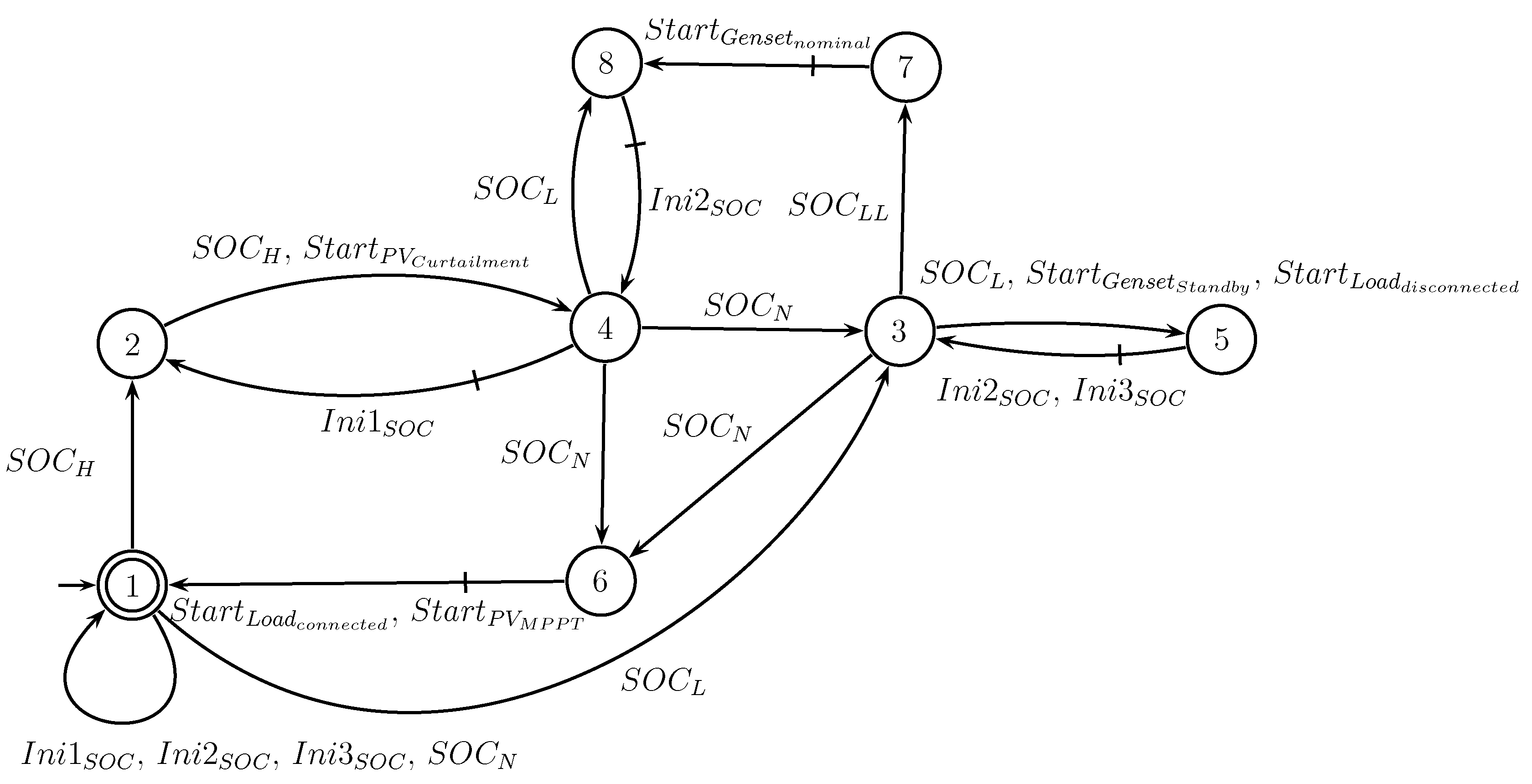
Figure 19.
Supervisor 2 - POI voltage support function.
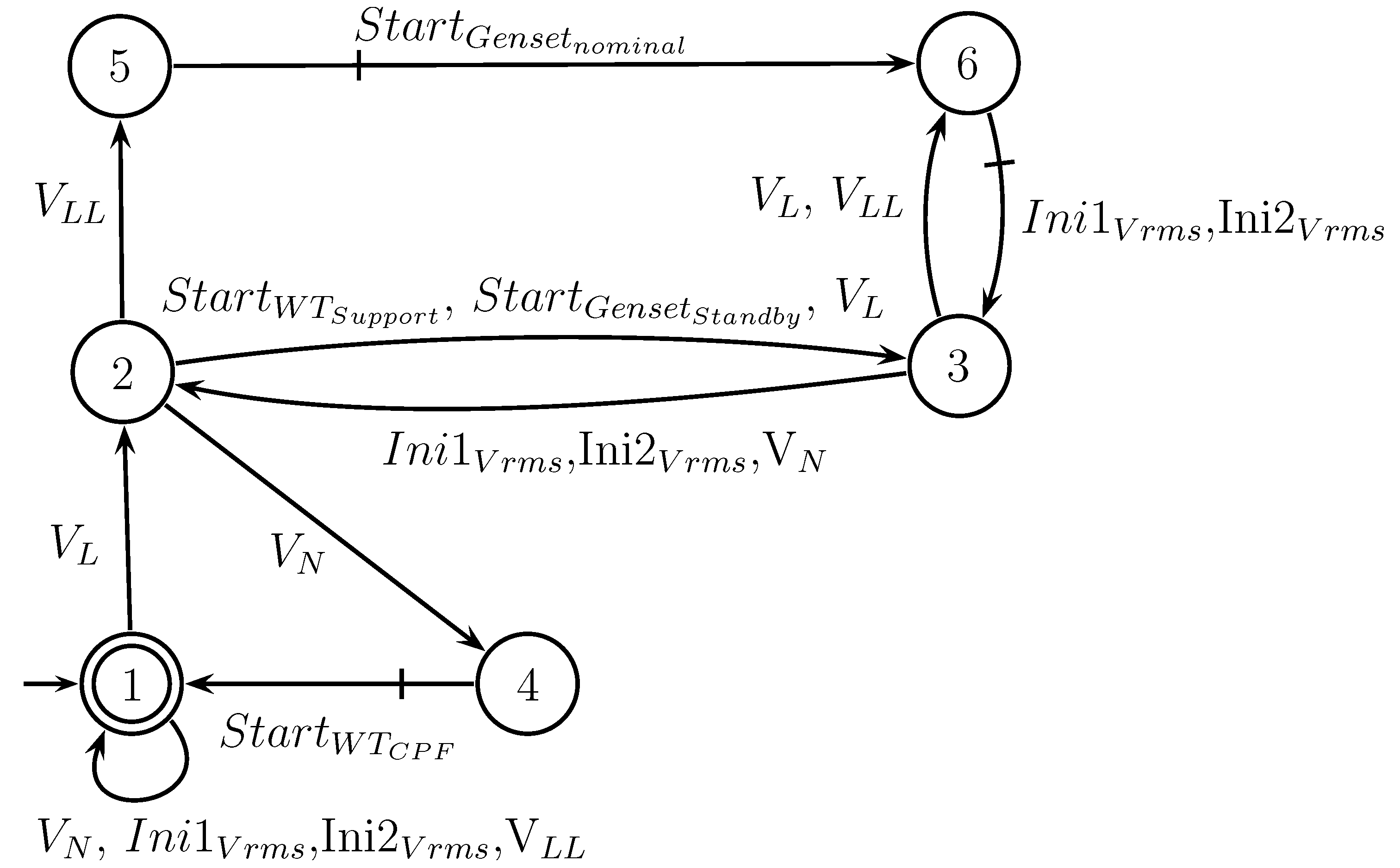
Figure 20.
Supervisor 3 - Peak shaving function.
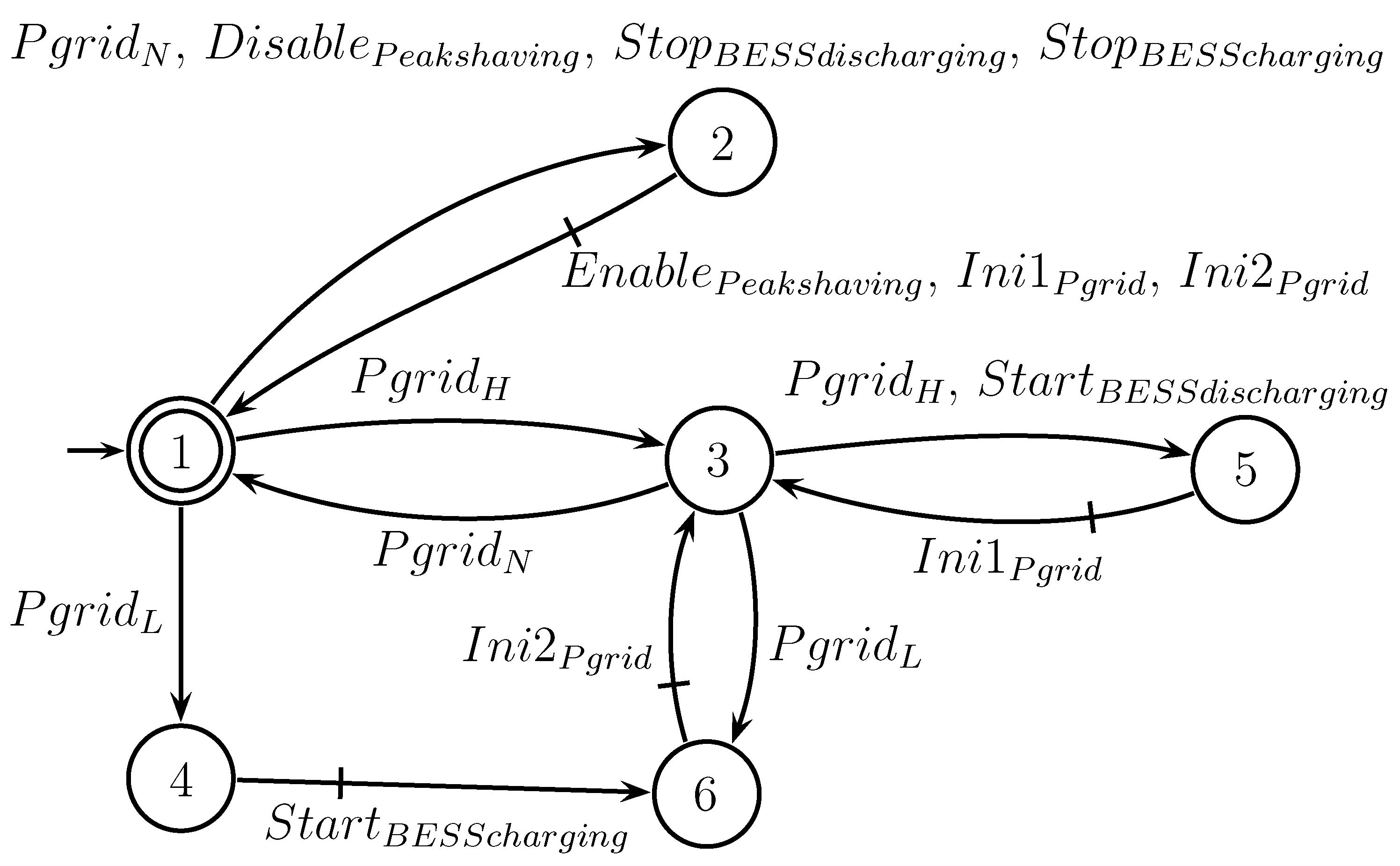
Figure 21.
Power consumption profile of critical and non-critical loads in the microgrid.
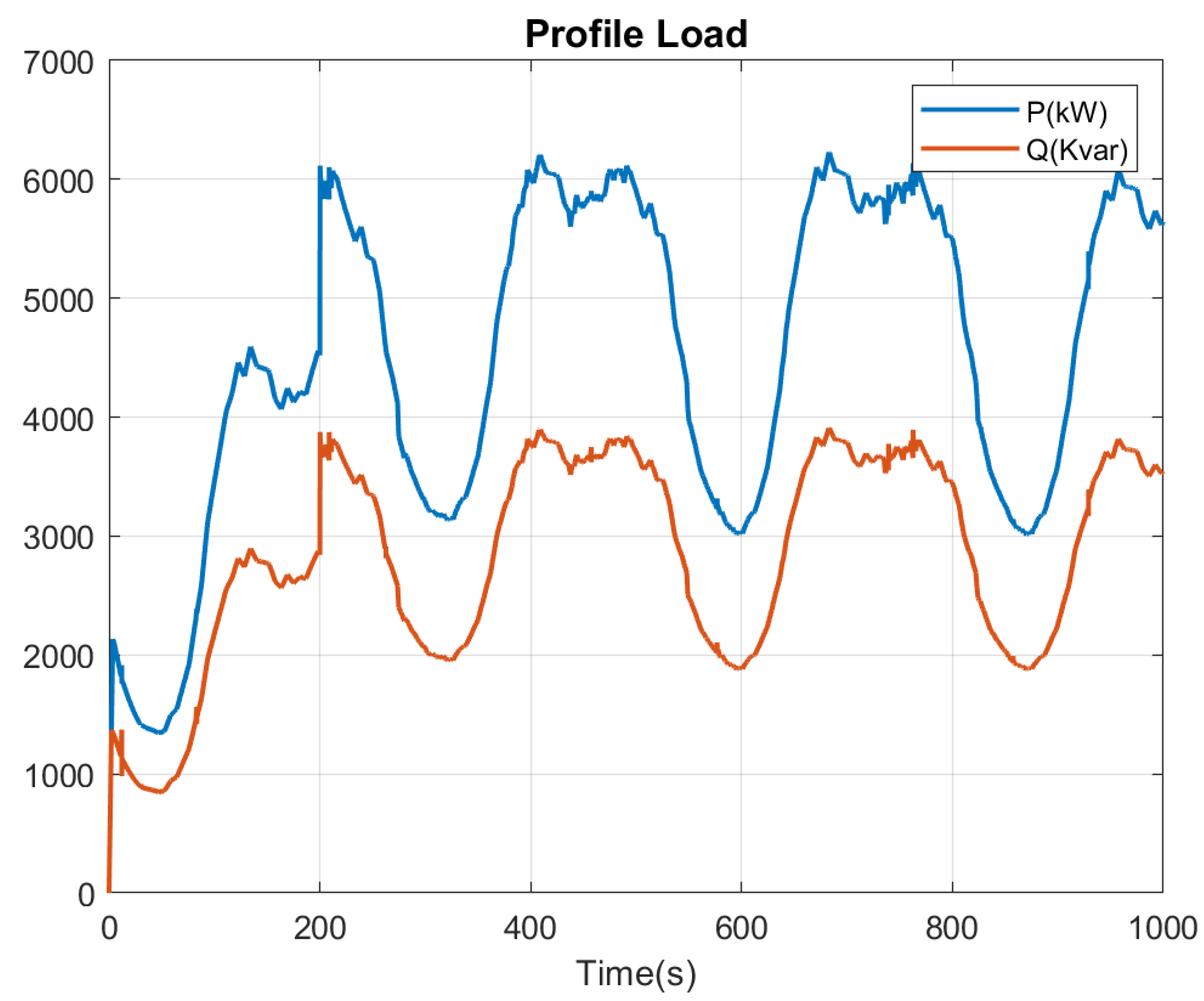
Figure 22.
Wind profile for wind generation system.
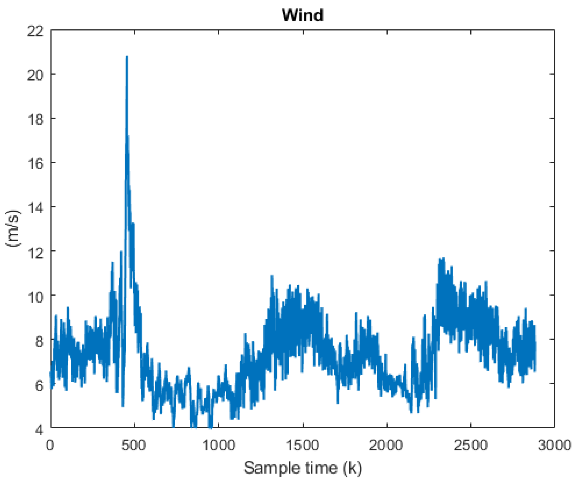
Figure 23.
Irradiance and temperature profile used for the PV system.
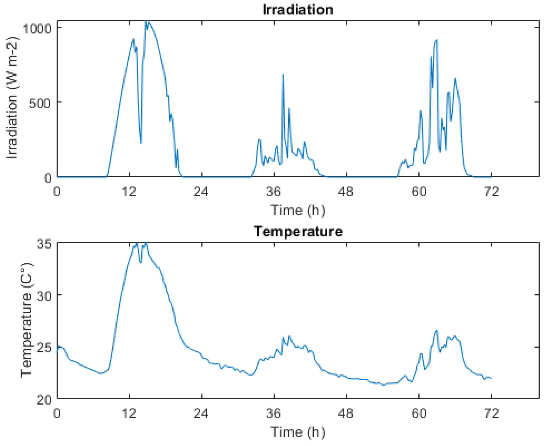
Figure 24.
Setup of the Hardware-in-the-Loop of the local controllers and supervisory control.
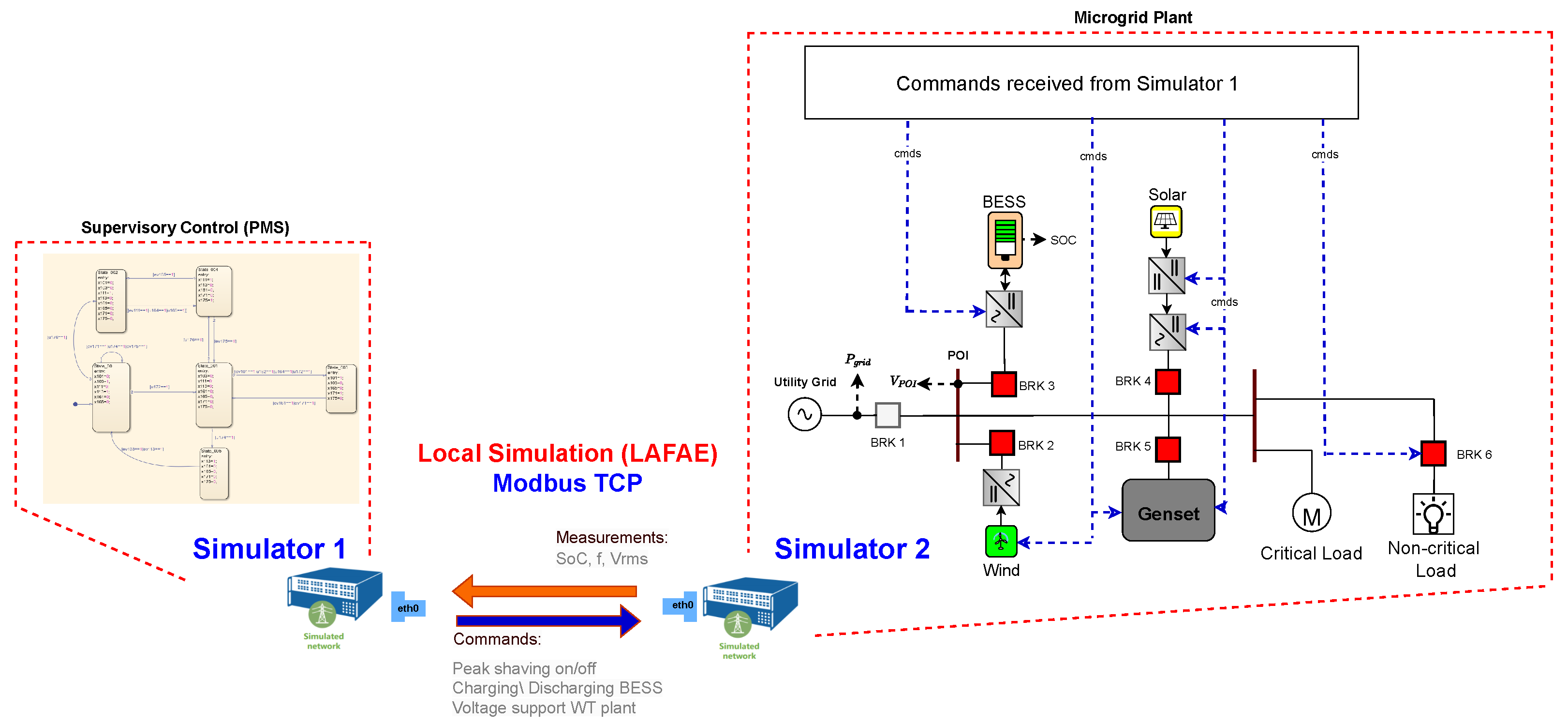
Figure 25.
Hardware-in-the-Loop testbed.
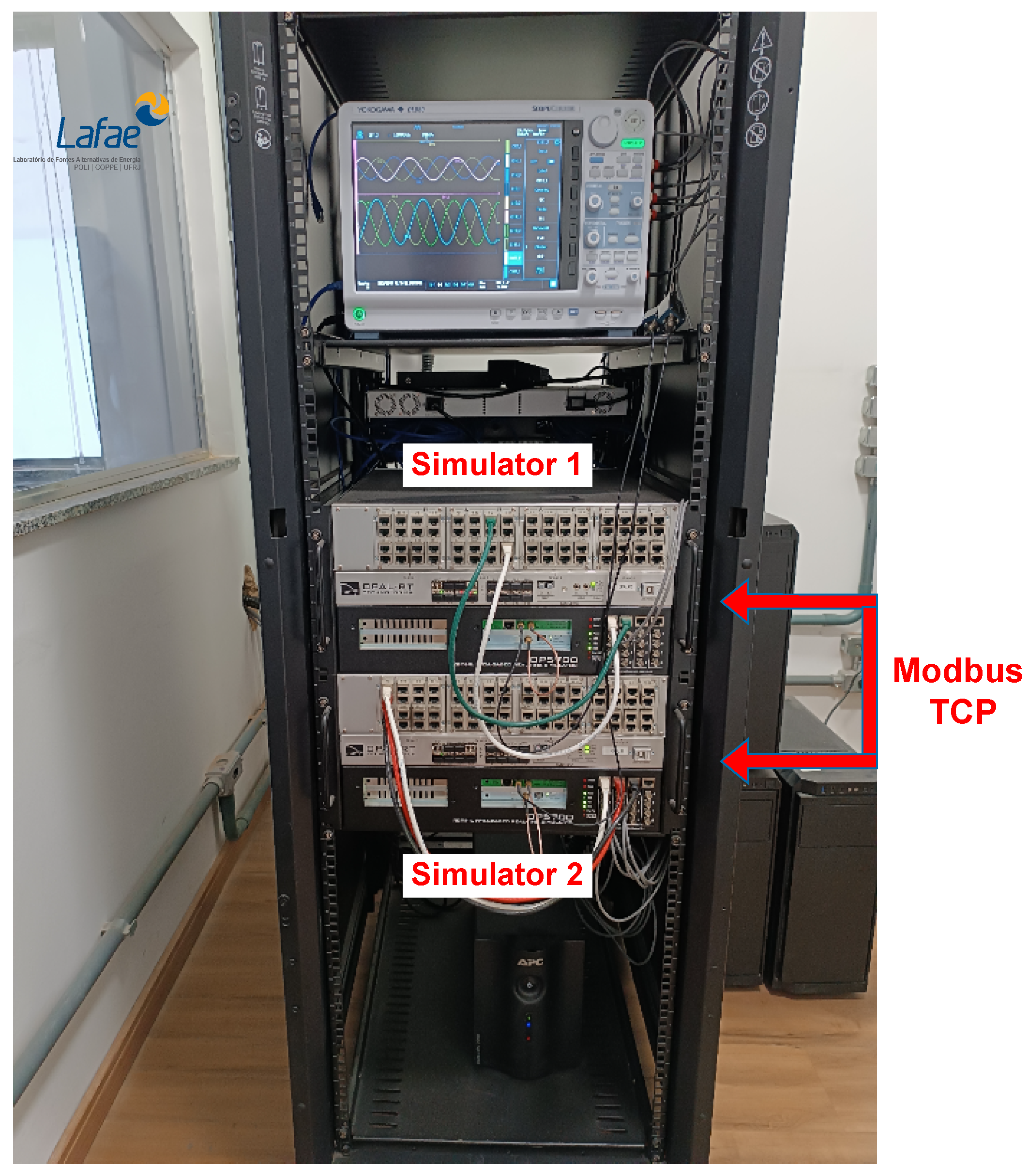
Figure 26.
Supervisor 1’s performance of peak shaving, active power of MG.
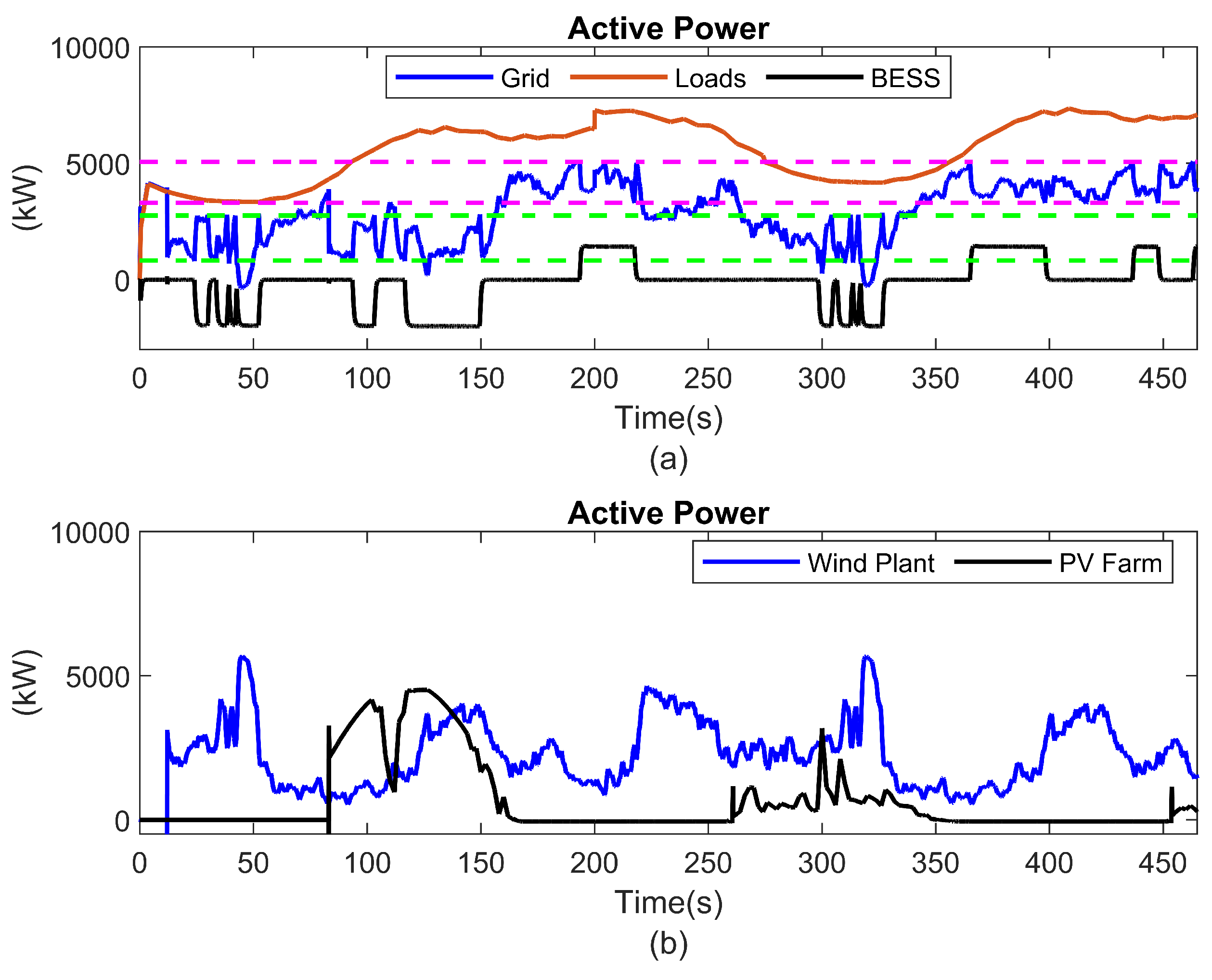
Figure 27.
Commands sent by SC and state of charge of BESS.
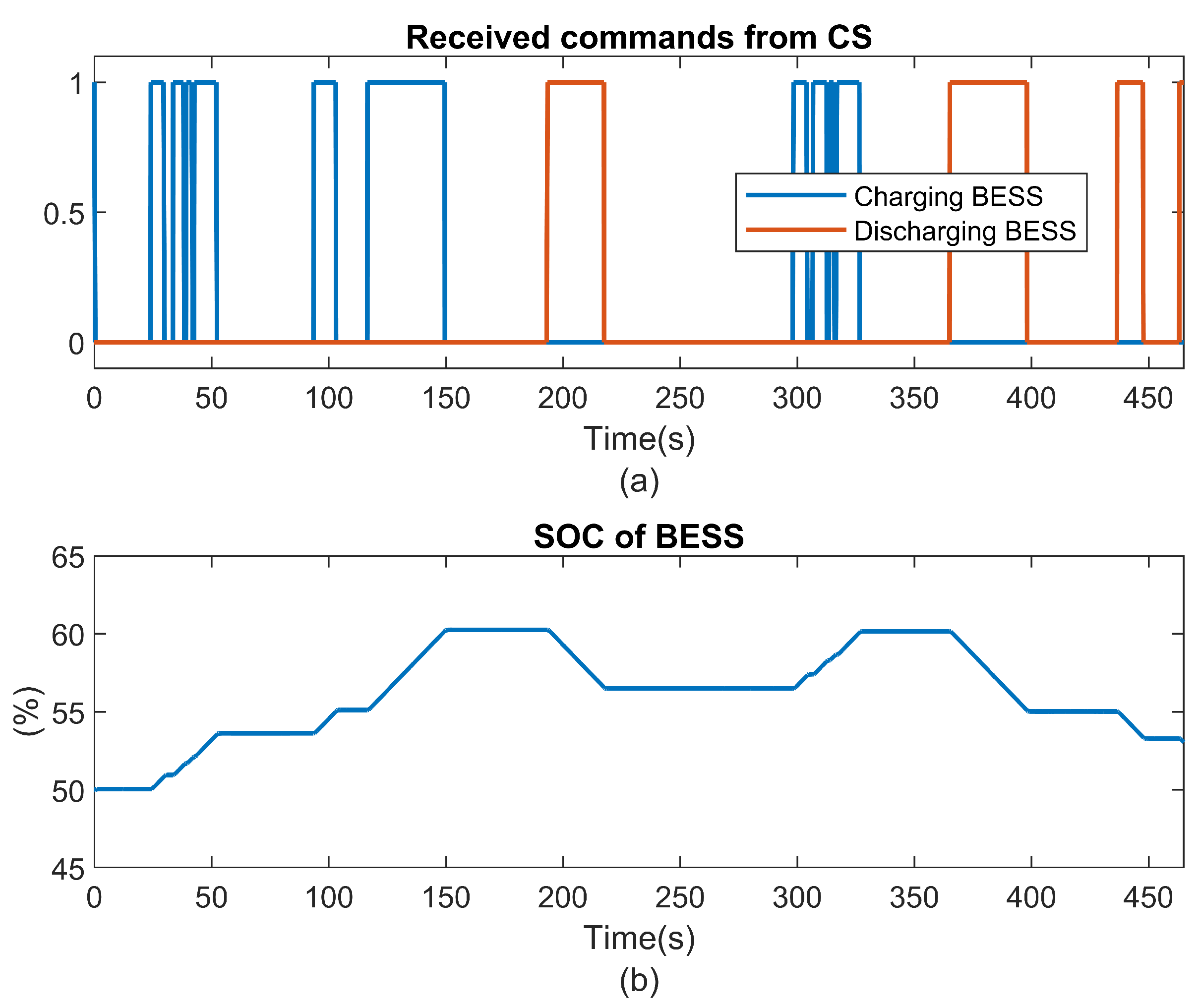
Figure 31.
Supervisor 3’s performance in managing the support voltage provided by the wind system.
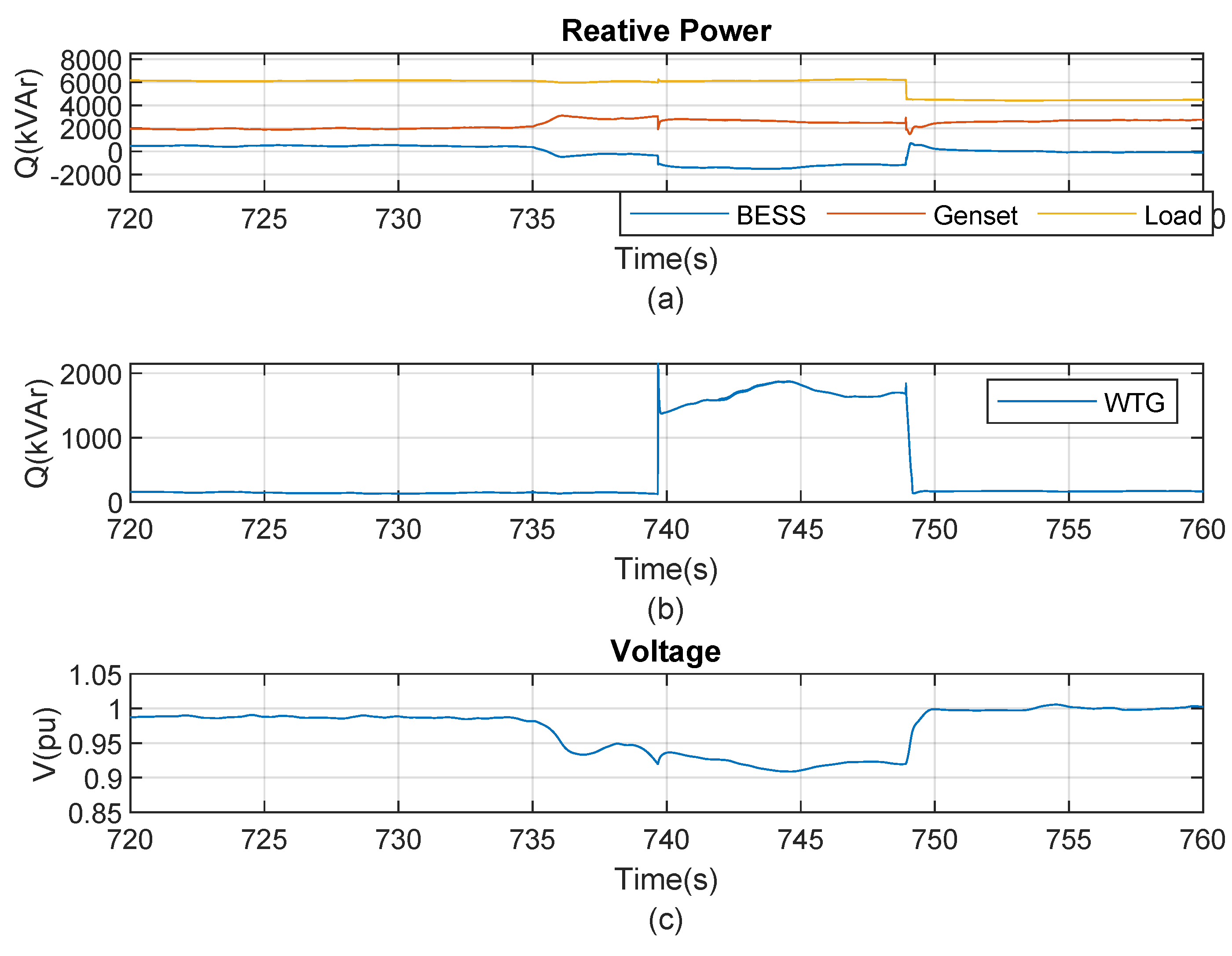
Figure 32.
Comparison between the operation of the system with the implementation of a supervisory control and the operation without its use.
Figure 32.
Comparison between the operation of the system with the implementation of a supervisory control and the operation without its use.
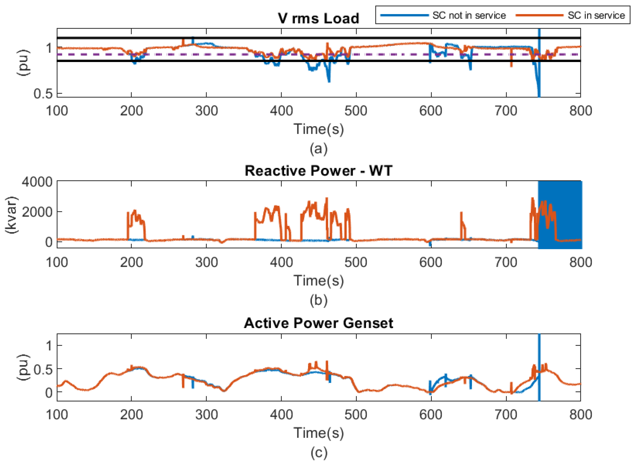
Table 1.
Table of events that are disabled by Supervisor in each state.
| State: | Disable events |
|---|---|
| 1: | , |
| 2: | , , |
| 3: | |
| 4: |
Table 2.
Description of the DERs automata model and peak shaving activation command shown in Figure 12.
Table 2.
Description of the DERs automata model and peak shaving activation command shown in Figure 12.
| Model | State | Events | Description |
|---|---|---|---|
| G1: PV | 1: MPPT 2:Curtailment |
X: Y: |
The PV system can operate in MPPT mode (state 1) or in curtailment mode (state 2). The events are enabled or disabled by the supervisors, depending on the operation of the system. |
| G2: BESS Operation | 1: BESS Standby 2: BESS Charging 3: BESS Discharging |
U: W1: V: W2: |
Operation mode of BESS is represented by a three-state automaton with four events. The BESS operating model is designed for taking into account charging, discharging and standby mode without power injection. |
| G3: Genset | 1: Genset at standby mode 2: Genset at nominal mode |
X: Y: |
The Genset is modeled with two states and two events. Event represents the injection of its nominal ative power considering a power factor of , while event indicates that the generator have to inject its minimum power, depending on the voltage and frequency of the grid. |
| G4: WT | 1: WT at Constant Power Factor 2: WT at Support voltage |
X: Y: |
The WT system can operate as a P-Q bus (state 1) working in the MPPT control, and as a providing voltage support function (state 2). |
| G5: Noncritical load Breaker | 1: Load connected 2:Load disconnected |
X: Y: |
The breaker that disconnects nonessential loads is modeled with two states and two events. Where state 1 is noncritical load connected and state 2 load disconnected. |
| G6: Peak shaving command | 1: Disable Peak Shaving 2: Enable Peak Shaving |
X: Y: |
The peak shaving mode is activated or deactivated by command, to do this, it is modeled with two states and two events. |
Table 3.
Description of the measurements of the microgrid in automata presented in Figure 13.
Table 3.
Description of the measurements of the microgrid in automata presented in Figure 13.
| Model | State | Events | Description |
|---|---|---|---|
| G7: BMS | 1: SOC 2: SOC 3: SOC 4: SOC |
X1,X2,X3: Initialization of BMS U: V: W: Y: |
Monitoring the maximum and minimum SOC of the BESS:When the SOC is above , the PV goes into curtailment mode and when the SOC returns below , the PV returns into MPPT mode. If SOC is below , the noncritical load is disconnected. When the SOC drops below , the Genset must inject its nominal power. |
| G8: Pgrid | 1: 2: 3: |
X1,X2: Initialization of Pgrid U: V: W: |
Monitoring the grid’s active power: The grid’s power must not exceed the contracted value. If , the BESS goes into discharge mode. If , the BESS goes into charging mode. Otherwise, BESS is in stamdby mode. |
| G9: Vrms | 1: 2: 3: |
,: Initialization of U: V: W: V: |
Monitoring the POI’s RMS voltage: The voltage must not drop below , as required by the grid code. To ensure this, the WT and genset provide voltage support. When the voltage (Vrms) at the POI is above , the WT remains in constant power factor mode. If the voltage drops below , the WT switches to voltage support mode. If the voltage drop persists, the Genset also comes into operation to provide additional voltage support. |
Disclaimer/Publisher’s Note: The statements, opinions and data contained in all publications are solely those of the individual author(s) and contributor(s) and not of MDPI and/or the editor(s). MDPI and/or the editor(s) disclaim responsibility for any injury to people or property resulting from any ideas, methods, instructions or products referred to in the content. |
© 2025 by the authors. Licensee MDPI, Basel, Switzerland. This article is an open access article distributed under the terms and conditions of the Creative Commons Attribution (CC BY) license (http://creativecommons.org/licenses/by/4.0/).
Copyright: This open access article is published under a Creative Commons CC BY 4.0 license, which permit the free download, distribution, and reuse, provided that the author and preprint are cited in any reuse.


