
Submitted:
22 October 2024
Posted:
24 October 2024
You are already at the latest version
Abstract
Microgrids represent small-scale energy generation units with low cost-effectiveness, making use of renewable resources, such as photovoltaic and wind energy. These systems can operate both in connection with and independent from the primary power grid. The widespread adoption and expansion of microgrids are increasingly vital in light of the global shift towards minimizing fossil fuel consumption and promoting cleaner energy sources. Similar to conventional electrical networks, microgrids require Supervisory Control and Data Acquisition (SCADA) systems to ensure sustained and reliable operation.
In support of the proliferation and growth of microgrid networks, this paper proposes the implementation of an open-source SCADA system. This system, being platform-independent, significantly reduces the costs associated with microgrid implementation, thus aligning with the principles of social responsibility. The proposed SCADA system will be deployed on a simulated microgrid, featuring both photovoltaic and wind energy sources, and will include a Phase-Locked Loop (PLL) synchronization system for grid connection. The simulation will be carried out using the Matlab-Simulink environment, leveraging the power systems library.
The interface between Matlab and SCADA is done using an OPC Server. Additionally, the SCADA system will interface with an SQL database to facilitate the archiving of historical data.
Keywords:
Microgrid
; Open-Source Software
; Renewable Energy
; Energy Management
1. Introduction
The integration of unconventional renewable energy sources within Peru’s energy matrix has experienced limited progress, hindered by several critical barriers. These include the lack of supportive regulatory frameworks, the scarcity of skilled professionals, the prevailing economic conditions of the population, and the constrained availability of commercial solutions. Furthermore, these challenges are exacerbated by insufficient public awareness and widespread financial skepticism, resulting in continued dependence on unsustainable conventional energy sources and obstructing the transition toward a diversified and sustainable energy future [1].
In response to these pressing issues, this research proposes developing and implementing a cost-effective, free, open-source Supervisory Control and Data Acquisition (SCADA) system specifically tailored for microgrids. The proposed system aims to address the economic, technical, and financial barriers that currently impede the widespread adoption of microgrids by providing an accessible solution for their monitoring and control. Additionally, this research will formulate evidence-based strategies to address socio-cultural and awareness-related challenges, thereby fostering public acceptance and facilitating the shift away from fossil fuels. Through this initiative, the research aspires to contribute to the diversification of Peru’s energy matrix by promoting the adoption of sustainable energy sources.
The primary objective of this study is to design, develop, and implement a low-cost, open-source SCADA system for microgrid control and monitoring, with the ultimate goal of enhancing microgrid adoption in Peru.
To achieve this objective, the research will focus on simulating some microgrid configurations, using the Matlab-Simulink platform. This will include modeling a microgrid for a residential community and incorporating renewable energy sources such as solar panels, to assess feasibility and performance. Additionally, a stand-alone microgrid configuration will be simulated, integrating components such as solar panels, a Maximum Power Point Tracking (MPPT) controller, a battery management system, and an inverter to optimize energy management. The study will also simulate the operation of a grid-connected microgrid, focusing on seamless load transfer and synchronization with the main electrical grid.
Following the simulation phase, the development of the SCADA system will proceed. This will involve designing an intuitive user interface for real-time visualization of key microgrid parameters, including power generation, consumption, and storage. Automated control algorithms will be developed to optimize the energy flow within the microgrid and manage its interaction with the grid. The system will also incorporate a secure data logging and reporting mechanism to monitor microgrid performance and support ongoing maintenance.
Once developed, the SCADA system will be validated through a case study in a microgrid environment, with a residential setting. Comprehensive user manuals and training materials will be created to facilitate the adoption of the system by local communities and technical staff. Finally, the research findings will be disseminated through publications and presentations, contributing to the advancement of microgrid technology and promoting greater access to sustainable energy solutions in Peru.
In addition to this introductory section, this article is divided into 11 sections. Section 1 presents the state of the art of this article. Section 2 is presented the related works. Section 3 is detailing the preliminaries. Section 4 describes development and implementation. Section 5 details microgrid system implementation. Section 6 details a single-phase inverter design with PLL anchoring to the external grid. Section 7 is presented Electrical Network. Section 8 is presented OPC communication. Section 9 is presented RapidSCADA Server. Section 10 is presented SQL Server and Reporting Services. Section 11 concludes and summarizes the achievement of the objectives of the article.
2. Related Works
In this Section 2, we review several key studies that were examined during the research related to the development and implementation of SCADA systems for microgrids.
One study describes the design and implementation of a cost-effective SCADA system with a web interface, developed for application in Hybrid Renewable Energy System (HRES) microgrids. This system was specifically created for the Renewable Energy Laboratory at Universitat Politècnica de València (LabDER-UPV) in Spain, to provide a reliable and low-cost control and data acquisition system to enhance research on microgrid stability and energy generation [3].
Another study focuses on the monitoring of photovoltaic systems mounted on the exterior surfaces of rapidly expanding green buildings. The primary objective in this case was to enable centralized monitoring and intervention as needed, thereby improving the operational efficiency of these systems [4].
A comprehensive literature review on the electrical, thermal, and optical modeling of photovoltaic systems has also been conducted. This review examines the key models proposed in the literature for predicting the behavior of photovoltaic systems, emphasizing the importance of accurate modeling for optimizing system performance [5].
Finally, research has explored the implementation of a SCADA system designed to enhance the reliability, safety, and economic efficiency of microgrid operations. In this study, the SCADA system serves as the hub of an intelligent microgrid monitoring platform, connecting the lower central controller with an upper World Wide Web (WEB) monitoring system [6].
3. Preliminaries
3.1. SCADA Systems, Definition and Concepts
Supervisory Control and Data Acquisition (SCADA) systems are crucial components in the monitoring and control of industrial processes and critical infrastructure. These systems integrate both hardware and software to facilitate the collection of data from sensors and other field devices, while also enabling the transmission of commands to actuators and other control mechanisms. The fundamental premise underlying SCADA systems is their ability to centralize and automate the supervision and control of complex processes, thereby enhancing operational efficiency and safety.
A SCADA system comprises a comprehensive set of hardware and software that enables operators to oversee and manage industrial processes, facilities, and equipment remotely and in real time. These systems are designed to gather data from connected sensors and devices through a communication network, subsequently providing operators with real-time information. This information is critical for informed decision-making and effective process control, as it allows operators to monitor system performance and intervene when necessary [7].
The key functions of SCADA systems can be detailed as follows:
- Real-time Supervision: SCADA systems provide continuous monitoring of process status and equipment conditions. Operators are presented with visual information via graphical interfaces that include charts, alarms, and variable values. The monitoring and control software processes and displays the data collected by the data acquisition hardware and also facilitates the transmission of commands to control devices. This capability is grounded in the premise that real-time data visualization and interaction are essential for maintaining operational oversight and responding to dynamic process conditions.
- Control: Through the SCADA interface, operators can execute control actions over processes and equipment. These actions may involve the activation or deactivation of equipment, adjustment of parameters, or modification of process settings. Control devices within the SCADA system, such as programmable logic controllers (PLCs), programmable automation controllers (PACs), and relays, enable the activation or deactivation of field devices like motors and valves. The underlying assumption here is that centralized control from a SCADA system enhances operational efficiency by allowing immediate and precise adjustments to be made in response to real-time data.
- Data Acquisition: SCADA systems are equipped to collect data from various field sensors and devices, including meters and sensors for temperature, pressure, and level. This data is stored in a database for subsequent analysis. The data acquisition hardware, which includes sensors, transducers, signal converters, and input/output modules, plays a pivotal role in capturing and transmitting accurate field data. The assumption driving this function is that comprehensive data acquisition is fundamental for informed decision-making and process optimization.
- Alarm and Notification: SCADA systems generate real-time alarms and notifications when abnormal conditions or deviations from established limits are detected. This functionality allows operators to respond swiftly to critical situations, thereby minimizing potential risks to process continuity and safety. The premise here is that early warning through automated alarms is critical for preventing or mitigating adverse events in industrial processes.
- History and Recording: SCADA systems are also tasked with recording and storing historical data related to system and process performance. This historical data is invaluable for trend analysis and maintaining a log of past events, which can be used for diagnostic purposes and for improving future process operations. The implicit premise is that historical data analysis is essential for continuous improvement and long-term process optimization.
- Automation: SCADA systems are often integrated with automatic control systems, such as PLCs and Distributed Control Systems (DCS), to facilitate process automation and autonomous decision-making. This integration reflects the premise that automation is key to enhancing process efficiency, reducing human intervention, and ensuring consistent operational performance.
- Integration with Other Systems: SCADA systems can be integrated with a variety of other systems, including energy management systems, building management systems, and enterprise resource planning (ERP) systems. Communication networks, which may include protocols such as Ethernet, Wi-Fi, Modbus, and Profibus, enable data transmission between different components of the system. The premise behind this integration is that interoperability among different systems enhances overall operational efficiency and enables more holistic management of industrial processes.
- Functions: The overarching functions of a SCADA system include process monitoring and control, data acquisition and recording, reporting, and integration with other automation and information systems. SCADA systems also provide diagnostic capabilities and enable remote programming and control of processes. The hidden premise is that a multifunctional system that combines these capabilities is essential for the comprehensive and effective management of complex industrial operations.
- Simulink in MATLAB
Simulink, a simulation and design tool developed by MathWorks, is extensively utilized in engineering for the modeling, simulation, and analysis of dynamic systems. Integrated with MATLAB, Simulink provides an interactive environment that facilitates the design and simulation of complex and multidisciplinary systems. The core premise behind Simulink’s popularity in engineering is its ability to represent systems using a block diagram approach, allowing for model-based design of multidomain systems without the necessity of manual coding [8].
This software simplifies the development of complex systems through a model-based design methodology. This approach enables frequent virtual simulations and design validation, which are essential for ensuring the accuracy and reliability of system designs before physical implementation. Additionally, Simulink supports automatic code generation for production in various programming languages, including C, C++, and VHDL, reflecting the premise that automating the transition from model to code can significantly streamline the development process and reduce the potential for human error [8].
Simulink also enables users to explore different design concepts within a multidomain simulation environment. This capability allows for large-scale system simulations using reusable components and libraries, facilitating iterative design and optimization. Furthermore, Simulink supports the deployment of simulation models across various testing environments, including desktop simulations, real-time testing, and hardware-in-the-loop (HIL) scenarios. The underlying assumption here is that comprehensive simulation capabilities are crucial for evaluating and refining system designs under diverse conditions, thereby enhancing the robustness and reliability of the final product [8].
Moreover, Simulink supports Model-Based Systems Engineering (MBSE), which encompasses the entire lifecycle of system development, from requirements capture and system analysis to detailed design, implementation, and testing, all within a systematic and integrated framework. The premise driving this approach is that MBSE, by providing a cohesive and structured process, enhances the efficiency and effectiveness of system development, ensuring that all aspects of the system are considered and optimized throughout the development lifecycle [8].
3.2. Characterization of electrical consumption and calculation of a photovoltaic solar generation system
The characterization process is based on Case 1, as outlined in the document titled Guide to the orientation of the efficient use of energy and energy diagnosis produced by the General Energy Efficiency Management [9]. This case study examines a single-family home within the class B economic sector, representative of an independent residential unit. The selection of this specific case reflects the premise that homes in this economic category present unique challenges and opportunities for energy efficiency improvements. By focusing on a typical class B home, the study aims to provide insights into the energy consumption patterns and potential efficiency measures applicable to similar households. The key characteristics of this home are detailed in Table 1.
Next, we will assess the power requirements needed to meet the daily electrical demand for the most frequently used appliances. This analysis is based on the premise that understanding the power consumption of these commonly utilized devices is essential for accurately estimating the overall energy needs of a household. The relevant power consumption data is summarized in Table 2.
The reference power will be established by calculating the average of the two highest power demands, which are associated with the electric stove and the microwave oven. This calculation yields a reference power value of 4050W. The underlying assumption is that these two appliances represent the most significant contributors to the household’s peak power demand, making their average a reliable indicator for further analysis.
4. Development and Implementation
4.1. Proposed Research Architecture and System Components
The architecture of the proposed research work is detailed below:
A simulated environment, coupled with real-time communication capabilities, is critical for accurately modeling and testing the proposed Microgrid system. This ensures that the results generated are not only reliable but also transferable to real-world applications. As depicted in Figure 1, the development of the proposal is fundamentally based on the use of a simulated system within the Simulink platform, which acts as a representative model of the Microgrid. In this configuration, an OPC server plays a crucial role as an intermediary, enabling seamless communication between the SCADA system and the simulated environment.
-
Microgrid System
- Solar panel system: This subsystem consists of an array of solar panels designed to generate up to 1000 Watts at peak performance;
- Battery System: The battery system includes a configuration of batteries with a total storage capacity of 50Ah, providing energy storage for the Microgrid;
- Inverter: The inverter is responsible for converting the direct current (DC) generated by the solar panels and/or the battery system into alternating current (AC), which is used to power standard electrical devices;
- External electrical network: This component represents the external electrical distribution system that the Microgrid may interface with.
-
OPC communication system
- OPC Server: Acts as the central hub for linking the data generated from the Microgrid simulation to other subsystems within the overall architecture;
- OPC Client – Simulink: This client communicates directly with the OPC server, transmitting the data generated from the Simulink-based simulation to the server;
- OPC Client –RapidSCADA: This client is responsible for receiving and processing the data transmitted to the OPC server by the Matlab OPC Client – Simulink [10].
-
Rapid SCADA SystemThe Rapid SCADA system is designed for data acquisition, visualization, and storage:
- Data acquisition: Data Acquisition: This component of the SCADA system captures and makes available the data collected from the OPC client [10];
- HMI: The HMI provides an intuitive and agile graphical interface that closely represents the real-world system, allowing for effective monitoring and control;
- History Subsystem: This subsystem is responsible for storing the data generated by the system, as well as providing reporting services for analysis and record-keeping.
5. Microgrid System Implementation
5.1. Photovoltaic System or Solar Panel Arrangement
The photovoltaic system has been engineered to deliver a maximum power output of 1000 Watts under optimal conditions. As depicted in Figure 2, Simulink offers a specialized library that facilitates the accurate representation of this system. This library allows for straightforward configuration, enabling adjustments to achieve different voltage, current, and power outputs as required. The underlying assumption is that using such a configurable library not only simplifies the modeling process but also enhances the system’s adaptability to various design specifications and simulation scenarios.
It is important to note that the simulation framework allows for the configuration of multiple solar panels connected either in parallel or in series. Additionally, key parameters such as open-circuit voltage and short-circuit current can be adjusted according to the specific characteristics of the panels being simulated. These capabilities ensure that the simulation accurately reflects the desired operational conditions of the photovoltaic system. Moreover, the system provides a graphical representation of the solar panel array’s current as a function of voltage, which can be easily generated using the Plot function. This feature is crucial for visualizing the performance characteristics of the simulated solar array.
For this simulation, the HH180 solar panel’s characteristics were employed as the basis for the model. It is crucial to emphasize that key input parameters – solar irradiance and temperature °C – plays a significant role in determining the panel’s power output. These parameters are critical as they directly influence the photovoltaic system’s efficiency and overall performance. As illustrated in Figure 3, the simulation results provide a detailed visual representation of the power output under specified conditions of irradiance and temperature.
In the context of photovoltaic (PV) generation, the buck-boost converter plays a crucial role in managing the output voltage from the solar panel, adjusting it to meet the system’s requirements. This converter can step up or step down the output voltage relative to the input voltage, depending on the operating conditions. This functionality is particularly important in PV systems, where the output voltage of the solar panel can vary significantly due to changes in solar irradiance and temperature. The buck-boost converter ensures that the system efficiently converts and utilizes the energy generated by the solar panels, regardless of environmental fluctuations.
The design process for such a converter was omitted here because it’s irrelevant for the main goal of this study.
The methodology for designing the solar panel system begins with calculating the standard and worst-case conditions for the solar panel arrangements, as detailed in Table 3 and Table 4, which present the respective values found during this process.
Following this, the switching frequency and voltage ripple are defined to ensure stable operation as .
Next, the internal resistance of the solar panel array is determined at the maximum power point under both standard and worst-case scenarios.
With these parameters in place, the output resistance is calculated using the following formula
Subsequently, the duty cycle at the maximum power point is computed, followed by the calculation of the output voltage and current in both scenarios.
The process continues with determining the inductor current, voltage ripple, and current ripple, which are essential for assessing the performance of the system.
Finally, the values for , L, and are obtained, completing the design process.
With the circuit elements selected, they are integrated into the panel system previously generated solar:
Figure 5.
Integrated power converter circuit (Own elaboration).
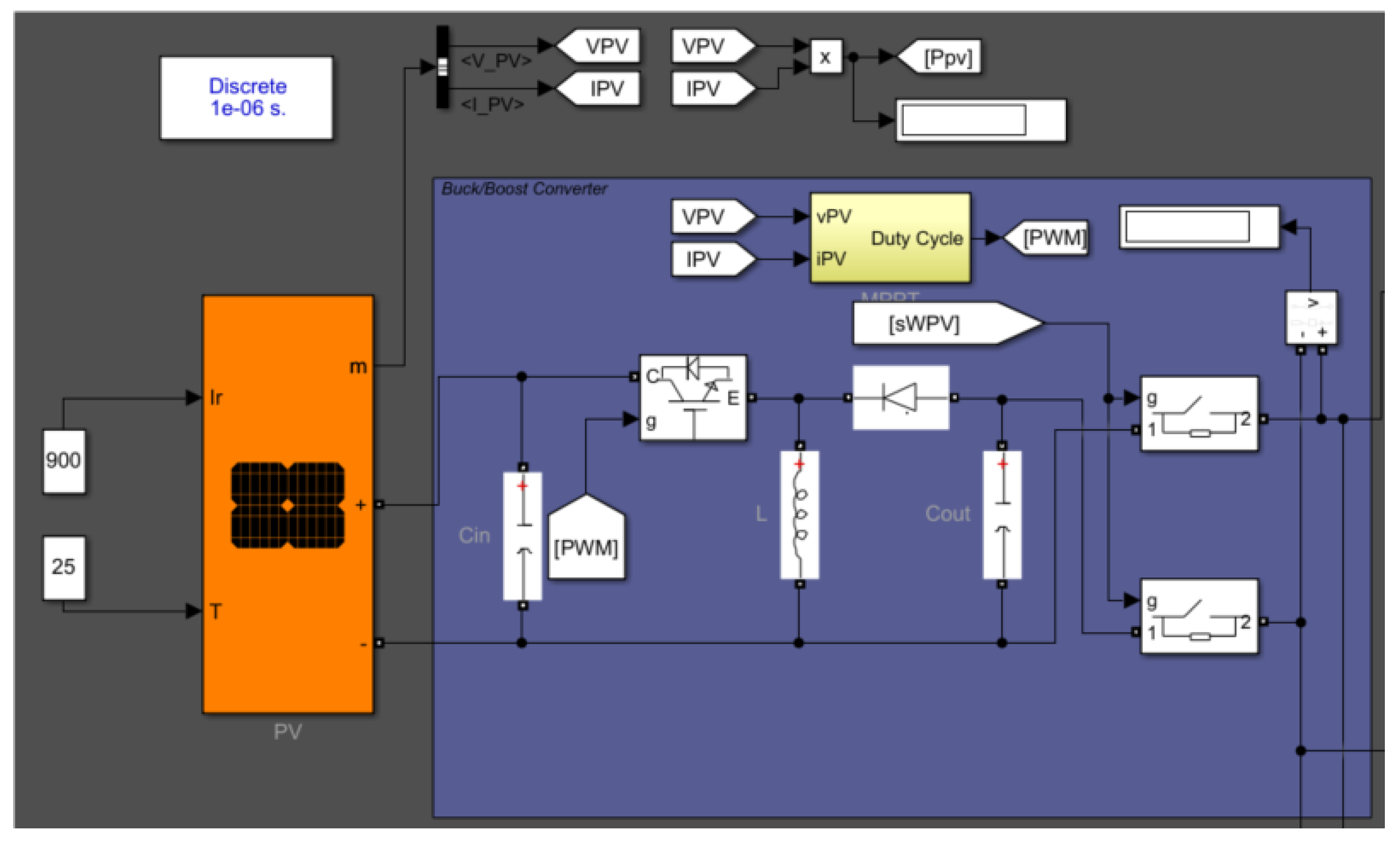
5.2. Maximum Power Point Tracking Algorithm Implementation
The Perturb and Observe (PO) algorithm was selected due to its simplicity and ease of implementation, making it an efficient choice for maximum power point tracking (MPPT) in photovoltaic systems. The sequence of operations within the algorithm is depicted in the flowchart provided in Figure 6.
The algorithm uses three persistent variables: , , and , which store the previous values of voltage, power, and reference voltage, respectively. These variables are essential for calculating the voltage and power variations between the current and previous iterations. If the algorithm is being executed for the first time, these variables are initialized with appropriate values (zero for and , and for ).
At each iteration, the algorithm calculates the instantaneous power generated by the solar panel, using the product of the measured voltage and the current supplied by the panel: . The variations in voltage and power compared to the previous iteration are then calculated. These values are critical in determining how the algorithm should adjust the reference voltage to maximize power.
As shown in Figure 7, which includes a representation of the solar panel, this mechanism is essential for maximizing energy generation efficiency and maintaining overall system stability.
The core of the P&O algorithm is based on analyzing how the variations in power and voltage influence the adjustment of the reference voltage. The procedure follows conditional logic.
When power varies , if power decreases , and voltage has also decreased , the algorithm adjusts the reference voltage to a higher value , as this indicates that the is at a higher voltage. If the voltage has increased , the reference voltage is reduced to find the at a lower voltage.
If power increases , and voltage decreases, the algorithm reduces the reference voltage , while if voltage increases, it increases the reference voltage . The goal is to observe how power changes with respect to voltage alterations.
If an increase in voltage results in an increase in power, the algorithm continues increasing the voltage until the MPPT is reached. Otherwise, it reverses the direction of the voltage adjustment.
If the power does not vary , the algorithm maintains the previous reference voltage, assuming it is near the maximum power point.
After adjusting , the algorithm checks whether the adjusted value falls within the established limits ( and ). If exceeds these limits, it is reset to the previous value , ensuring the system operates within a safe range. Finally, the algorithm updates the persistent variables , , and with the current values of , V, and P, respectively, ensuring that the next iteration has access to the necessary information for calculating voltage and power variations.
The control algorithm is integrated into a closed-loop system, which is realized through a MATLAB script. This system is designed to process two critical inputs: the current and voltage measurements from the solar panel array and to generate a single output that regulates the system’s operation. Specifically, the input signals, with emphasis on the voltage, are continuously monitored and compared with the output of the Perturb and Observe (P&O) algorithm. This comparison is essential for dynamically adjusting the operating point of the photovoltaic system, ensuring that it consistently tracks the maximum power point and optimizes energy harvesting efficiency. The integration of the P&O algorithm into this feedback mechanism is fundamental to achieving precise control over the system’s performance.
Subsequently, the discrepancy between the measured input voltage and the output generated by the MPPT controller is processed by a Proportional-Integral (PI) controller. The PI controller plays a pivotal role in minimizing this error by adjusting the system’s response based on both the present and accumulated errors over time. To achieve optimal system performance, the PI controller’s parameters were meticulously fine-tuned through a series of iterative tests and adjustments. This calibration process involved systematically refining the controller’s gains to enhance stability, response time, and accuracy, as illustrated in Figure 8. The result is a robust control strategy that effectively maintains the photovoltaic system’s operation at or near the maximum power point under varying conditions.
6. Single-Phase Inverter Design with PLL Anchoring to the External Grid
In the design of the inverter, a circuit comprising four MOSFET/IGBT transistors was employed to synthesize the AC signal, utilizing a pulse-width modulation (PWM) control scheme. To suppress high-frequency noise generated by the rapid switching transients of the transistors, an LCL filter is implemented at the output stage, ensuring smoother signal quality and compliance with power quality standards.
Figure 9.
DC/AC inverter circuit (Own elaboration).
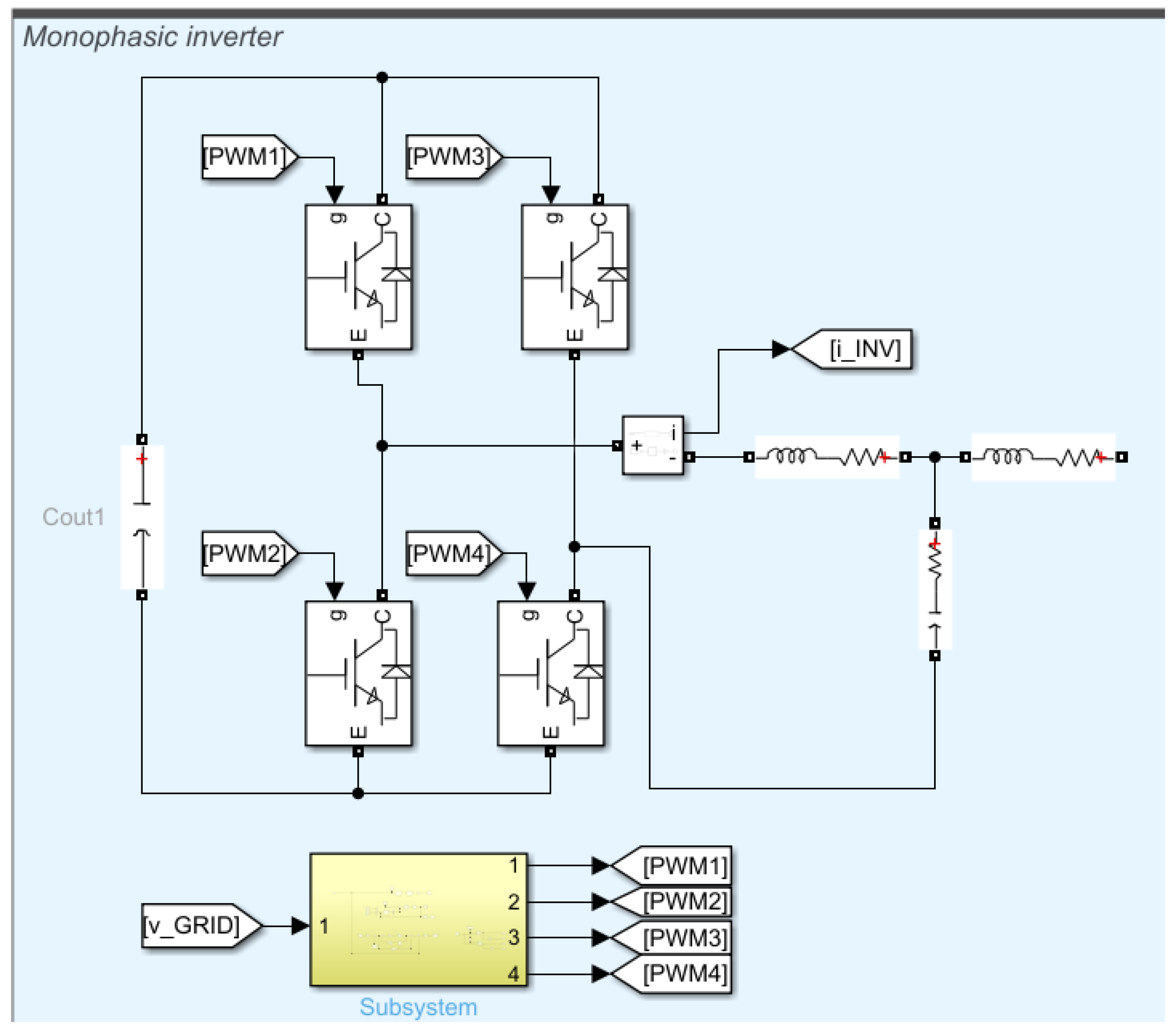
Figure 10.
LCL filter design [19].
Figure 10.
LCL filter design [19].
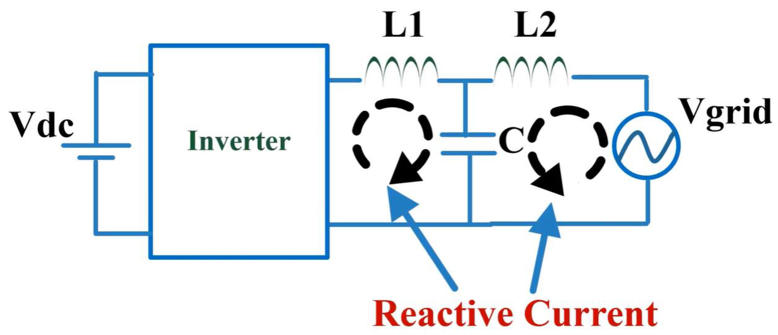
6.1. LCL Filter Design
The first step involves calculating the capacitor value, which is determined by the amount of reactive power absorbed under nominal conditions. In this case, the reactive power (Q) is limited to 5% of the apparent power (S). The relationship is expressed by the equation:
From this, we can derive the capacitor value (C) as:
For our system, the specific values to substitute are an apparent power , grid voltage , and frequency . Therefore, the calculated capacitor value is .
Next, the inductor value must be calculated. The inductor is selected based on the maximum permissible ripple in the current, which is limited to 20% of the nominal current. Additionally, the total inductance, represented as , is designed to ensure that the maximum voltage drop across the inductor does not exceed 10% of the nominal voltage.
Finally, a verification step is required for the calculated values. Using the reference frequency , it is necessary to check if the following condition is met:
The resonant frequency is calculated as:
Comparing this with the given bounds:
It is confirmed that the condition holds true.
6.2. PLL System Design
A Phase-Locked Loop (PLL) system enables precise phase control of our system by synchronizing it with a reference signal. In our application, the microgrid system aims to remain in phase with the electrical grid, which serves as the reference.
As part of the control strategy, the grid voltage is supplied as an input to the PLL system. The PLL then generates a reference current, which is compared with the inverter’s output current to ensure phase alignment and proper synchronization with the grid. The operation of the PLL system is illustrated in Figure 11.
The PLL system begins by converting the voltage signal using the Alpha-Beta transformation. Once the Alpha-Beta signals are obtained, they transform into the reference frame as illustrated in Figure 12.
In the transformation block, only the q-component of the signal is used. When this signal is processed by a subsequently integrated PI controller, it provides the angle . By applying the cosine or sine functions to this angle, we obtain the following:
- cos(t): Active Current
- sin(t): Reactive current
Since our goal is to obtain the active current, we select as the input signal for the PR controller. This signal is compared with the actual inverter current, and the resulting error is processed by the PR controller based on the selected gain values.
To determine the controller constants, the values of the LCL filter must first be considered.
The controller time constant is set at . Using this value, we can calculate the proportional gain as follows:
Additionally, we choose a value of .
Considering a frequency of 60 Hz, the gain can be calculated as:
7. Electrical Network
The electrical network was simulated using a generator operating at , with an load. For the purposes of the simulation, a purely active load was assumed, resulting in a power factor of 1 as illustrated in Figure 15.
8. OPC Communication
Matlab has an OPC client, which allows communication with an OPC server in Figure 16. This client will be in charge of transmitting the information to our SCADA server. The OPC server used is the Kepware KepServerEx , which in its freeware version is fully functional. Its limitation in the freeware version is that after 1 hour of use, it must be restarted (KEPServerEX - KEPinfilink, n. d.). The OPC communication maintains the following communication architecture:
In Matlab, the configuration is simple, and it is only necessary to enter the OPC server’s connection text Figure 17:
Once the connection text has been set, it is possible to map the tags available on the OPC server (previously created). Tags can be created from the Kepware server configuration window in Figure 18.
The following Figure 19 shows the captured values and the “Good” status as a quality flag, which confirms that the information received is correct.
9. RapidSCADA Server
Rapid SCADA is an open source platform for industrial automation. It contains several modules and tools that allow rapid creation of control and monitoring systems. This platform is installed on Windows and Linux operating systems. The minimum requirement is Microsoft Windows 7 SP1, or Microsoft Windows Server R2 with Internet Information Services (IIS) enabled. In addition to the platform .NET 4.7.2.
Once the platform is installed, proceed to make the configurations for communication. The main ones are the following:
- Creation of communication line: The type of communication is defined, either serial or IP, as well as the communication driver.
- Device creation: The communication parameters are defined according to the established protocol.
- Tag creation: The signals to be communicated are defined, as either input (read) or output (write).
In Figure 20 is shown OPC – RapidSCADA client configuration window.
In Figure 21 is shown the device creation window.
In Figure 22 is shown tags or signals configuration window.
Once the signals have been configured, we proceed to the configuration of the graphical part of the SCADA. Two types of displays will be used: tables and diagrams. The tables, as their name indicates, correspond to the presentation of the information in rows and columns according to the variable and the value. Diagrams present the information using a graphical representation of the system to be monitored. The diagrams are created with the RapidSCADA editing tool supported by a web browser, from where you can easily observe how the display will look.
In Figure 23 is shown data table, Rapid SCADA deployment.
In the Figure 24 below you can see the Rapid Scada, showing the values in real-time:
10. SQL Server and Reporting Services
An important part of the SCADA system is the ability to access previous records, in order to review past information that in a given situation could be useful to us. For this we used an external database, using the express version of MS SQL, which is free and has the necessary functionality to meet the objectives of our system. MS SQL Express is available on Microsoft’s official website, the installation is simple and is done in a few steps. What is important is to define the name, or instance of the database, i.e. how the database will recognize a request made from an external client to it. In our case, we modified the MS SQL instance so that it can be recognized only with the IP address of the host computer. In Figure 25 is shown alias Configuration for MSSQL Instance.
Once the instance is initialized and the SQL service is working correctly, a structure that will house our data must be created. In this case, a flat table was used, considering the time stamp as the main column. In Figure 26 is shown MS SQL history table.
With our structure created, we must activate the Rapid SCADA database module. Here we place the main communication parameters and then the sentence that will insert the data into the table previously created. In Figure 27 is shown RapidSCADA writing module configuration in Database.
In Figure 28 is shown data insertion screen in SQL instance.
The whole statement was created using SQL language. As seen in the Figure 29 it inserts the instantaneous values at a certain time in the previously created table.
Having made our data storage structure, we will now proceed to configure the reports. A report is a customized representation of the stored data. Using Microsoft’s Reporting Services, also free of charge, we can access the data stored in the database from a web server. Reporting Services also uses its own database for its configuration, which should not be confused with the previously created database. A SQL instance and an operating system with IIS are required as a prerequisite. With the reporting service installed, it is also necessary to have the Report Builder tool, which is also distributed free of charge on the Microsoft website.
In Figure 30 is shown reporting Services configuration window.
Access to the reports will be via the web, using the IP address 127.0.0.1 or, failing that, the argument “localhost”. In Figure 31 is shown reporting Services welcome screen.
Since the reporting system is a client of SQL Server, a connection text similar to the one created in Rapid SCADA is required. In Figure 32 is shown reporting Services configuration window for access to the SQL server.
This way we will have access to the data stored in the table we previously created. Once this step is done, it is possible to create the report as such. To do this we use the same web interface, which will automatically take us to the Report Builder for the construction of the report. In Figure 33 is shown Report Builder configuration window.
With the Report Builder we will give shape to the collected data, since it is a simple data structure, we will choose a table as a representation. With the report built, it is accessed through the web interface and we will be able to see the stored data. In Figure 34 is shown data report via web.
Thus, we completed the process of data submission and monitoring of our SCADA system.
11. Conclusions
In this article, a microgrid was successfully simulated using the environment Matlab Simulink considering the data capture subsystems energy, storage, and connection to the electrical grid. The SCADA system was developed in an open-source environment, that is, without resulting in cost, which encourages using these solutions for applications where the economic factor is determining to carry out the cape. The systems licensed in their express version were sufficient to complete the application, since the microgrid information does not require more robust solutions, they are presented as reliable alternatives and viable for real applications. The auxiliary history and reporting systems were configured correctly managing to store the information generated by the Microgrid for later reference. It was possible to correctly integrate the various systems that make up the final application, demonstrating that it is possible to use applications SCADA for the monitoring and control of microgrids, without incurring additional costs and stimulating its use and massification. The consumption of a home was characterized, where it was shown that the investment in solar energy, can be recovered between 1 and 2 years, depending on the power acquired. The RapidSCADA solution complements these systems, by providing a fast and effective way of monitoring them without representing an additional cost.
Author Contributions
For research articles with several authors, a short paragraph specifying their individual contributions must be provided. The following statements should be used D.J.C.Q., T.F.S., J.A.B.L. and G.A.E.E. conceived and designed the study; D.J.C.Q., T.F.S., J.A.B.L. and G.A.E.E., were responsible for the methodology; M. A. V. S., J.A.B.L. performed the simulations and experiments; D.J.C.Q., T.F.S., E.R.L.V. reviewed the manuscript and provided valuable suggestions; D.J.C.Q., T.F.S., E.R.L.V. and E.R.L.V. wrote the paper; G.A.E.E. and A.O.S. were responsible for supervision. All authors have read and agreed to the published version of the manuscript.
Acknowledgment
This research was funded Universidad Nacional de San Agustin Arequipa (UNSA). This research was funded and supported by the Coordenação de Aperfeiçoamento de Pessoal de Nível Superior—Brasil (CAPES)—Finance and Conselho Nacional de Desenvolvimento Científico e Tecnológico (CNPq).
Abbreviations
The following abbreviations are used in this manuscript:
| PWM | Pulse Width Modulation |
| PLL | Phase-Locked Loop |
| PI | Proportional-Integral |
| P& O | Perturb and Observe |
| MPPT | Maximum Power Point Tracking |
| AC | alternating Current |
| DCS | Distributed Control Systems |
| SCADA | Supervisory Control and Data Acquisition |
| WEB | World Wide Web |
| HRES | Hybrid Renewable Energy System |
References
- Espinoza, R.; Luque, C.; Muñoz-Cerron, E.; De La Casa, J. Barreras a superar en el intento de una intervención masiva de sistemas FV conectados a la red en el Perú. Tecnia 2017, 27(1), 7–13. [Google Scholar] [CrossRef]
- Carlos Vargas-Salgado, Jesus Aguila-Leon, Cristian Chiñas-Palacios, Elías Hurtado-Perez, Low-cost web-based Supervisory Control and Data Acquisition system for a microgrid testbed: A case study in design and implementation for academic and research applications, Heliyon, Volume 5, Issue 9, 2019, e02474, ISSN 2405-8440. [CrossRef]
- Carlos Vargas-Salgado, C.; Aguila-Leon, J.; Chiñas-Palacios, C.; Hurtado-Perez, E. Low-cost web-based Supervisory Control and Data Acquisition system for a microgrid testbed: A case study in design and implementation for academic and research applications. Heliyon 2019, 5, e02474. [Google Scholar] [CrossRef] [PubMed]
- Ertuğrul, A.; Gürkan, K.; Ersoy, A. . Design and development of data acquisition system (DAS) for panel characterization in PV energy systems. Measurement 2023, 221, 113425. [Google Scholar]
- Aslan Gholami, A.; Ameri, M.; Zandi, M. Roghayeh Gavagsaz Ghoachani, Electrical, thermal and optical modeling of photovoltaic systems: Step-by-step guide and comparative review study. Sustainable Energy Technologies and Assessments 2022, 49, 101711. [Google Scholar] [CrossRef]
- Li, S.; Jiang, B.; Wang, X.; Dong, L. Research and Application of a SCADA System for a Microgrid. Technologies 2017, 5, 12. [Google Scholar] [CrossRef]
- Loshin - Tech Target. (2021). What is supervisory control and data acquisition (SCADA)? https://www.techtarget.com/whatis/definition/SCADAsupervisorycontrol-and-data-acquisition.
- Matlab. (s. f.-a). Simulación y diseño basado en modelos con Simulink - MATLAB. Mathworks2022. https://la.mathworks.com/products/simulink.html.
- Osinergmin. (2023). Guía de Orientación del Uso Eficiente de la Energía y de Diagnóstico Energético. https://www.gob.pe/institucion/minem/colecciones/25400-guias-de-orientacion-del-uso-eficiente-de-la-energia.
- Matlab OPC. (s. f.). OPC Standards Communication - MATLAB and Simulink - MathWorks América Latina. MATLAB. Mathworks 2022. https://la.mathworks.com/help/icomm/opc.html.
- Young, G. O. Synthetic structure of industrial plastics. Plastics 2nd Ed. New York, NY, USA: McGraw-Hill 1964, 3, 15–64.
- Chen, W. K. Linear Networks and Systems. Belmont, CA, USA: Wadsworth. 1964, 3, 123–135.
- Duncombe, J. U. Infrared navigation—Part I: An assessment of feasibility IEEE Trans. Electron Devices 1959, ED-11(1), 34–39. [CrossRef]
- Wigner, E. P. Theory of traveling-wave optical laser. Phys. Rev 1965, 134, A635–A646. [Google Scholar]
- Kurss, H.; Kahn, W. A note on reflector arrays. IEEE Transactions on Antennas and Propagation 1967, 15(5), 692–693. [Google Scholar] [CrossRef]
- Reber, E. E. ; Michell, R. L. ; Carter, C. J. Oxygen absorption in the earth’s atmosphere. Aerospace Corp., Los Angeles, CA, USA 1988, 1, 102.
- Davis, J. H.; Cogdell, J. R. Calibration program for the 16-foot antenna. Elect. Eng. Res. Lab., Univ. Texas 1987, 1, 006–69. [Google Scholar]
- Transmission Systems for Communications, 3rd ed. , Western Electric Co., Winston-Salem, NC, USA. 1985, 1, 44–60.
- Risk, W. P.; Kino, G. S.; Shaw, H. J. P. ; Kino, G. S. ; Shaw, H. J. Fiber-optic frequency shifter using a surface acoustic wave incident at an oblique angle. Opt Lett. 1986, 11, 115–117. [Google Scholar] [CrossRef] [PubMed]
Figure 1.
Overview of the research proposal (Author’s elaboration).
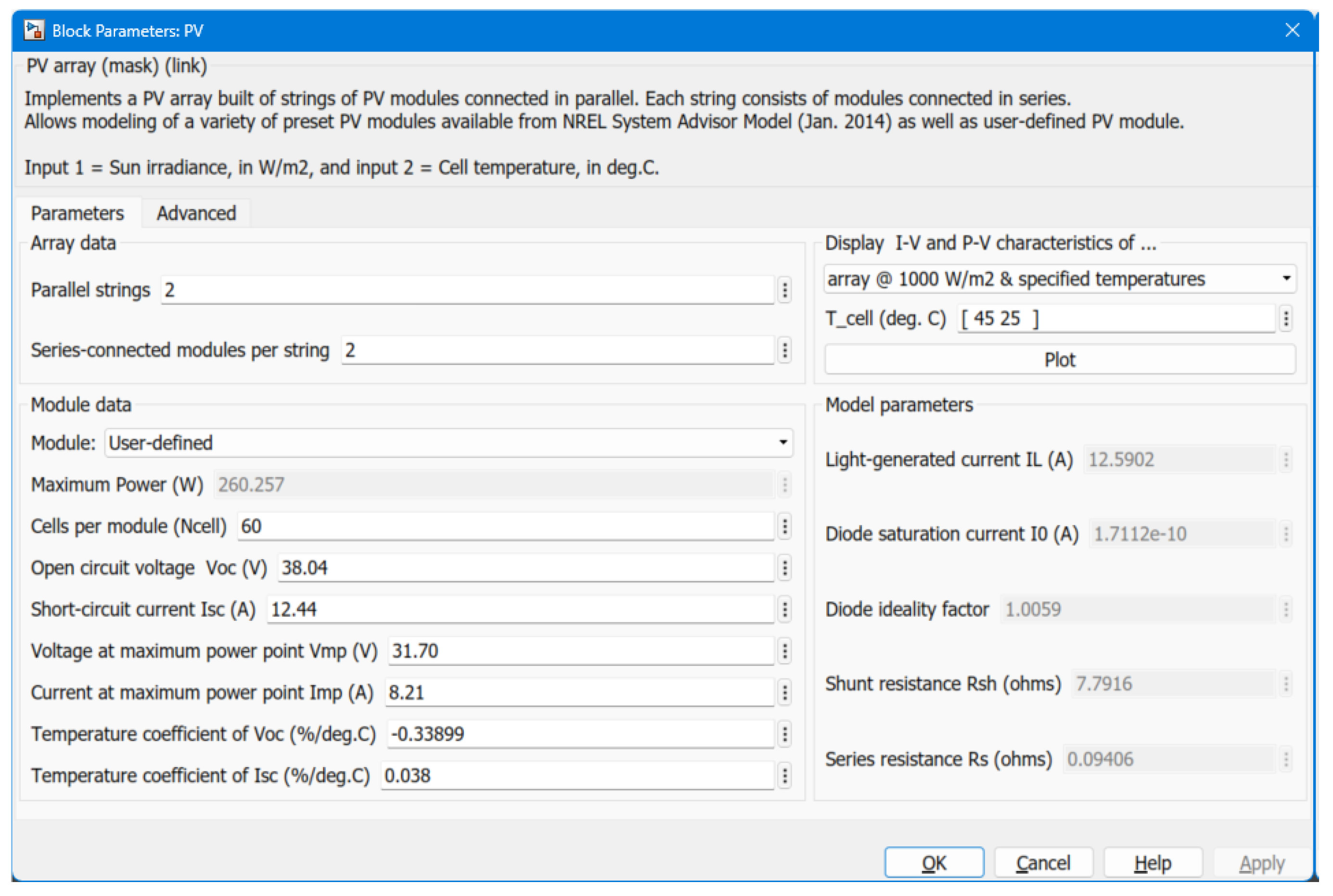
Figure 2.
Solar Panel Array Configuration Window.
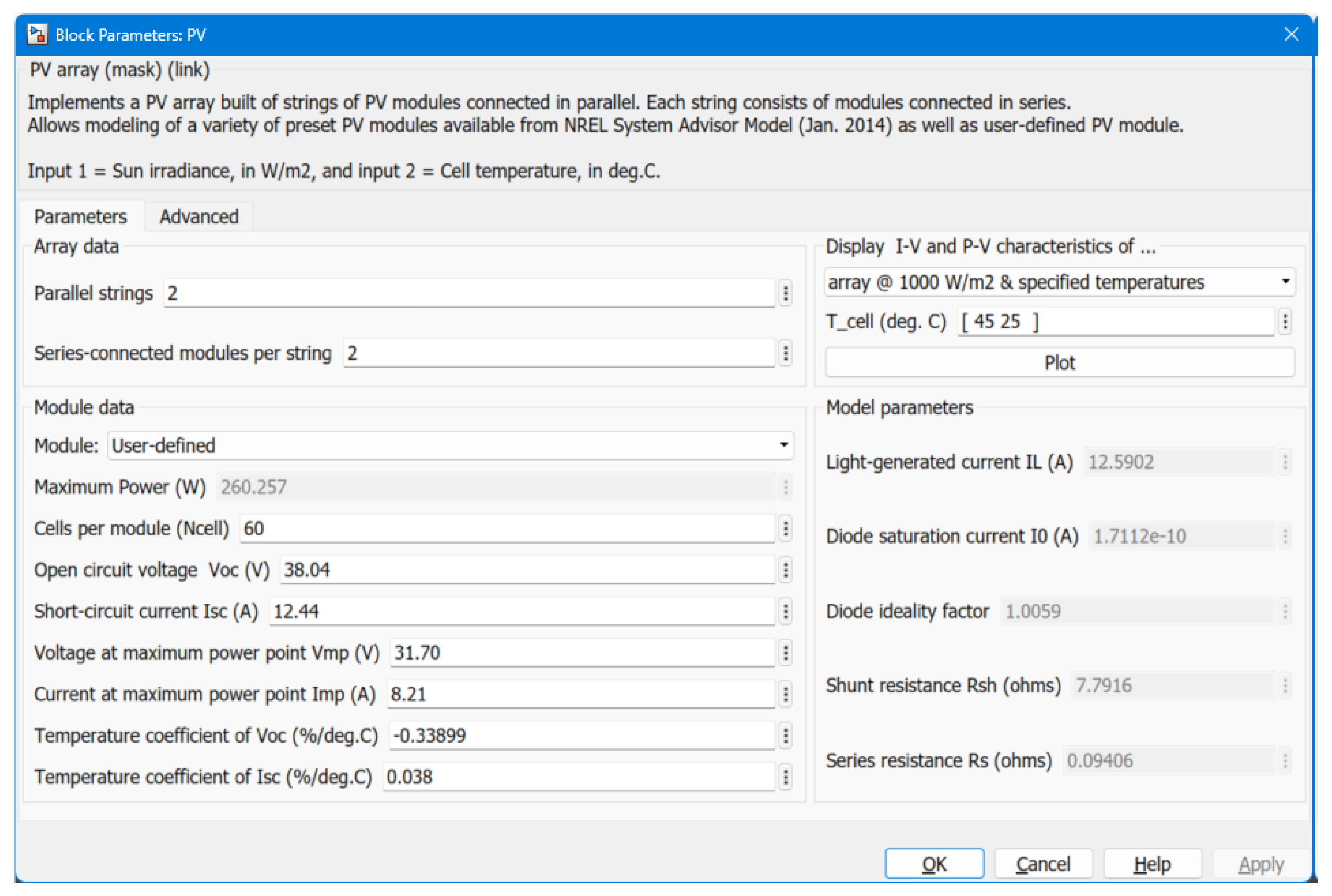
Figure 3.
Graphical representation of the solar panel array.
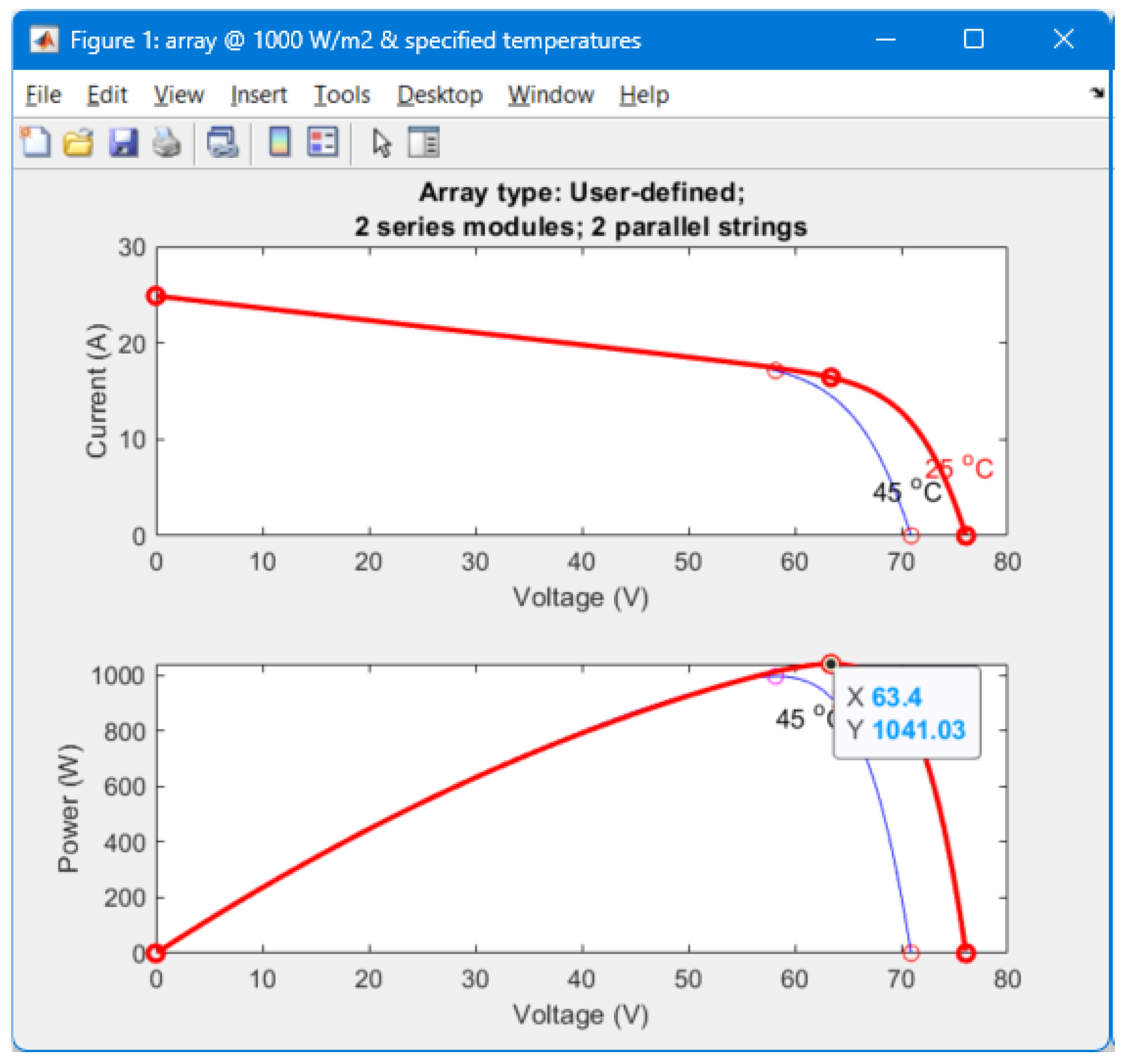
Figure 4.
Representation of the panel with its input parameters.
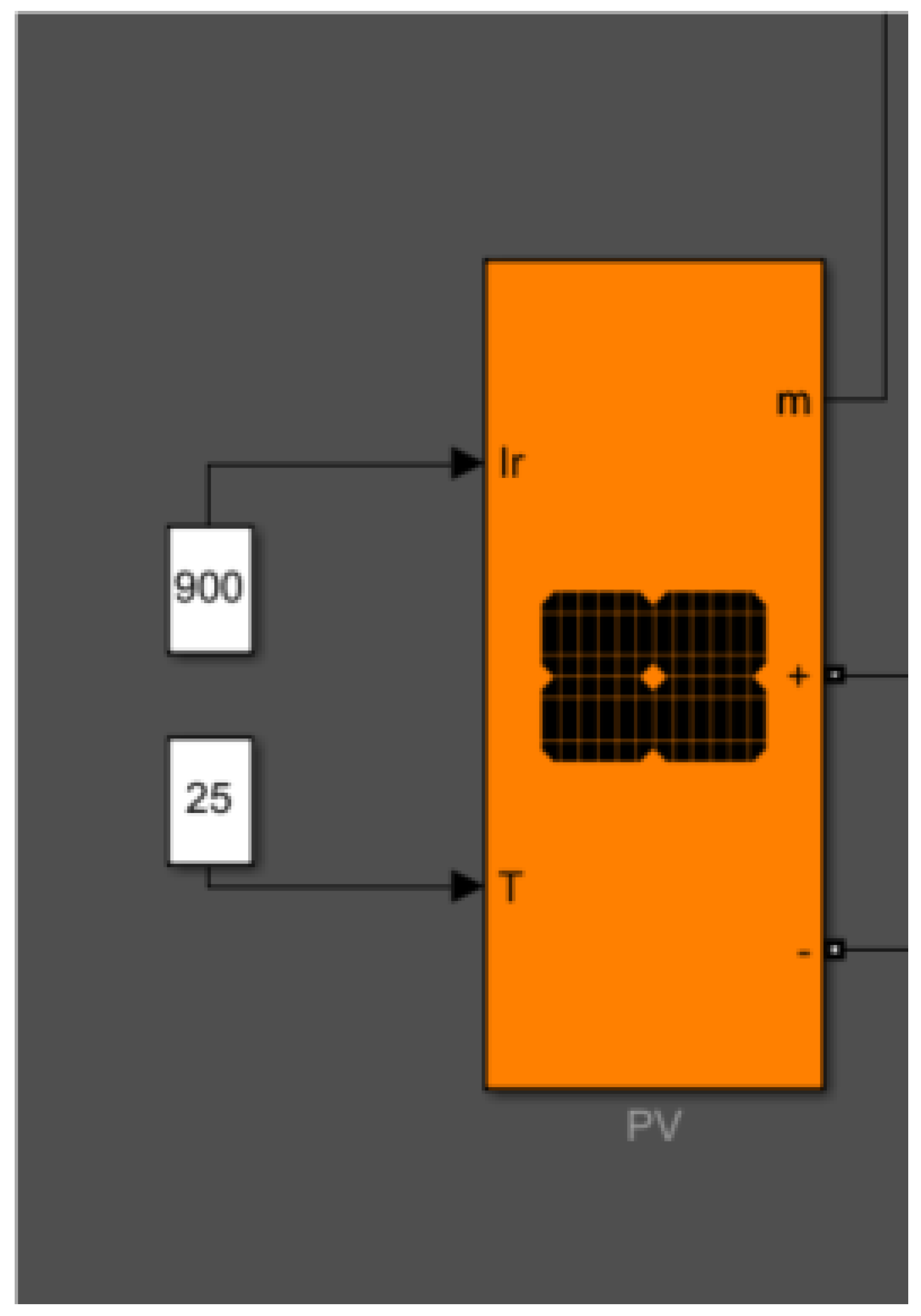
Figure 6.
Flowchart of the Perturb and Observe (PO) Algorithm for Maximum Power Point Tracking (Own elaboration).
Figure 6.
Flowchart of the Perturb and Observe (PO) Algorithm for Maximum Power Point Tracking (Own elaboration).
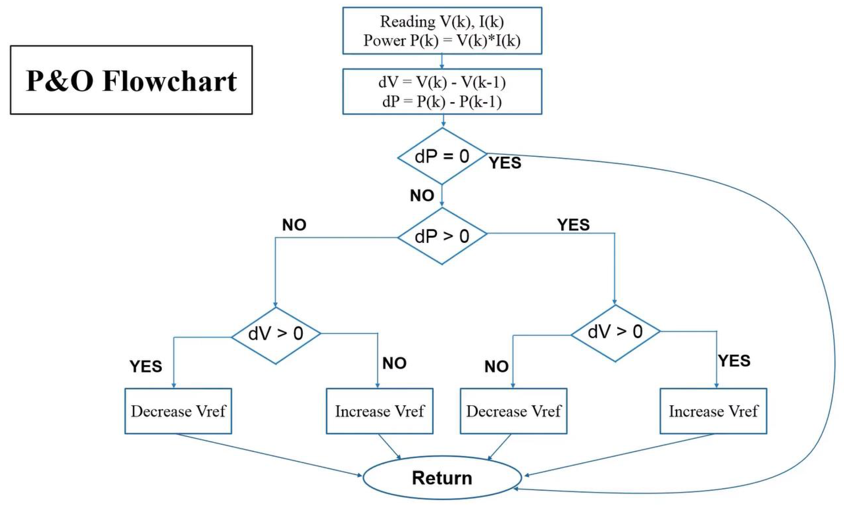
Figure 7.
MPPT controller in the Buck-Boost converter system (Own elaboration).
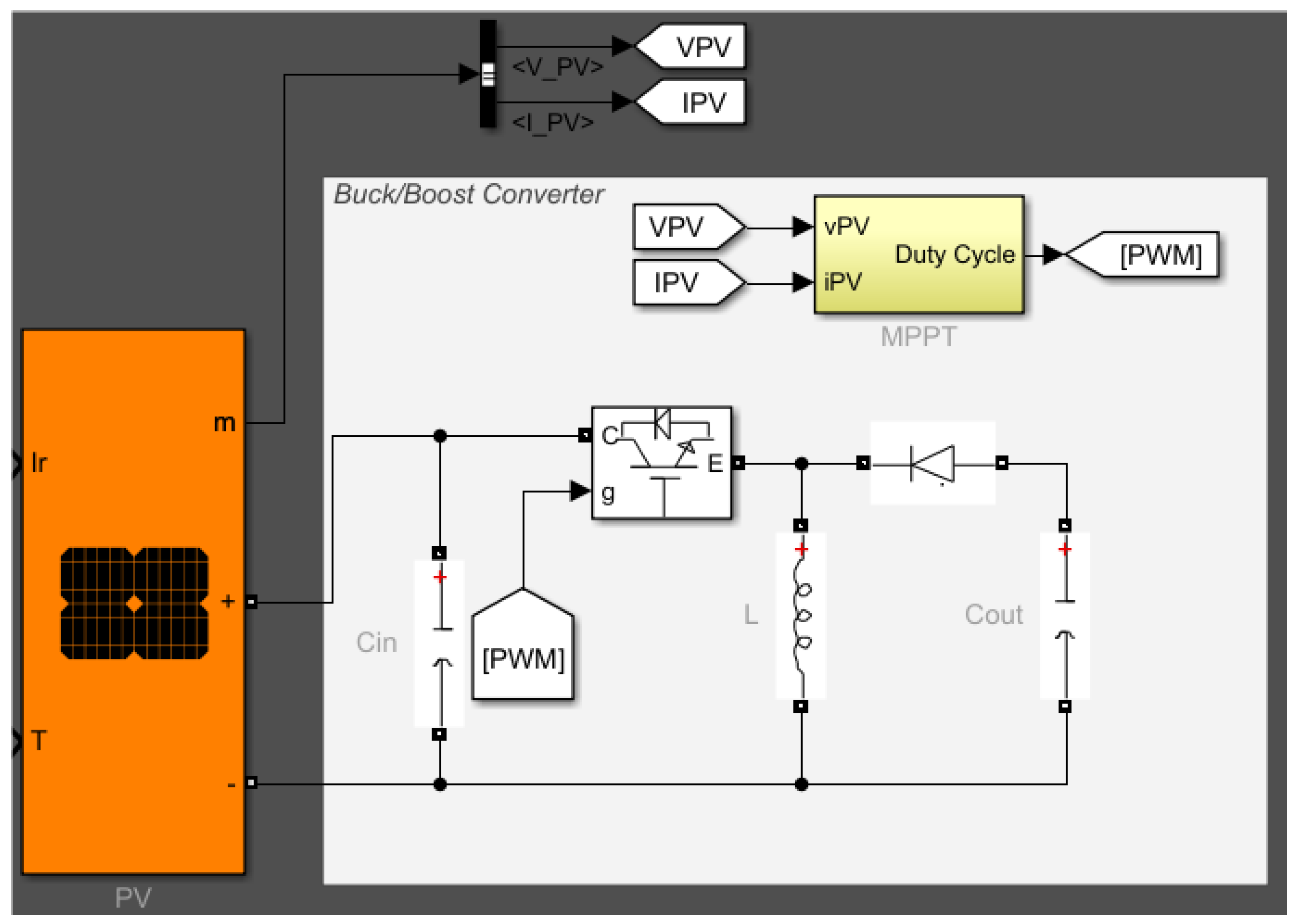
Figure 8.
Implementation of P& O algorithm.
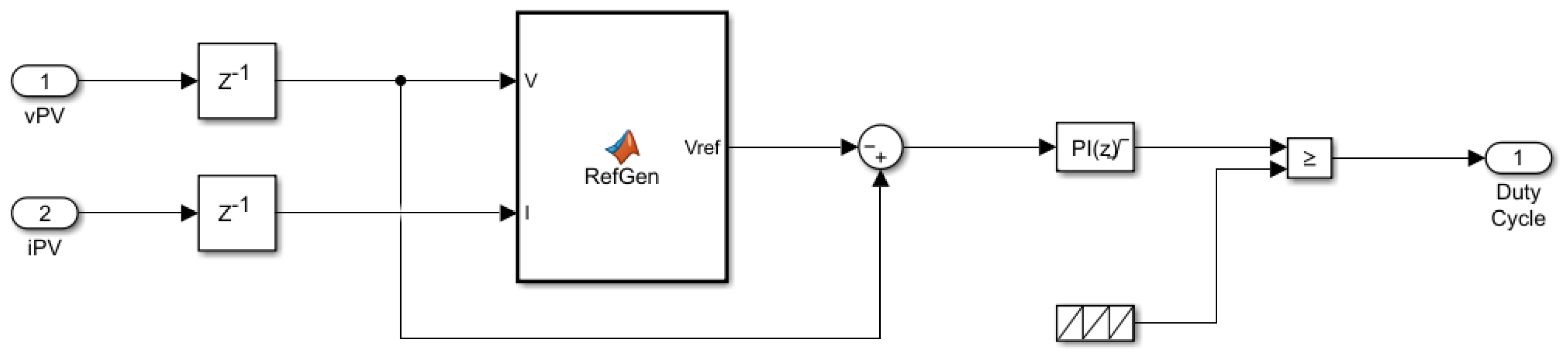
Figure 11.
Functional diagram of the grid-connected inverter.
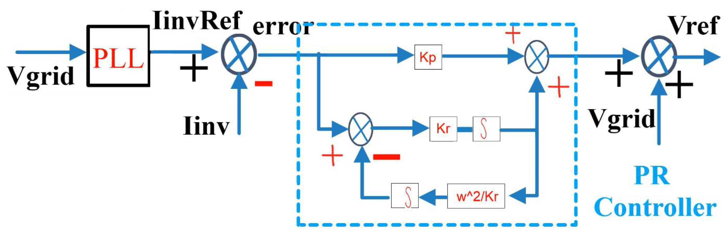
Figure 12.
Alpha-Beta to conversion.
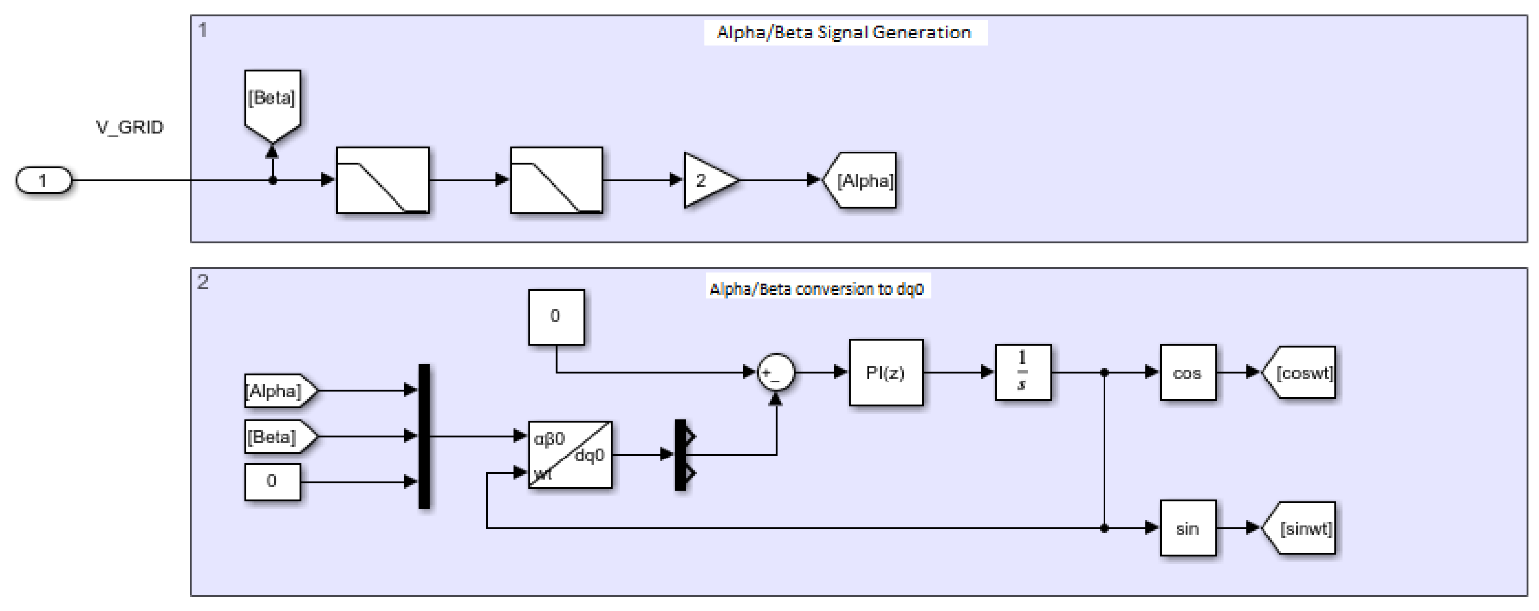
Figure 13.
PWM signal generation for IGBT gates.
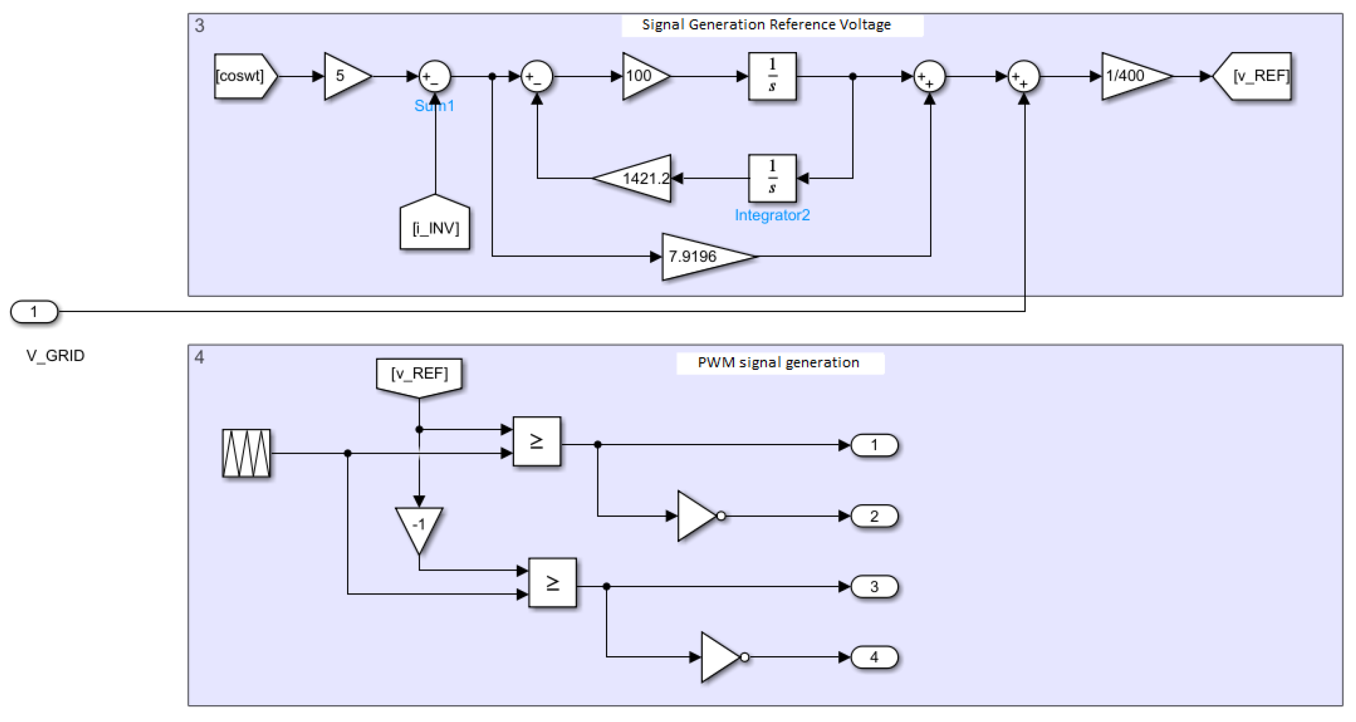
Figure 14.
PWM signal generation scheme [19].
Figure 14.
PWM signal generation scheme [19].
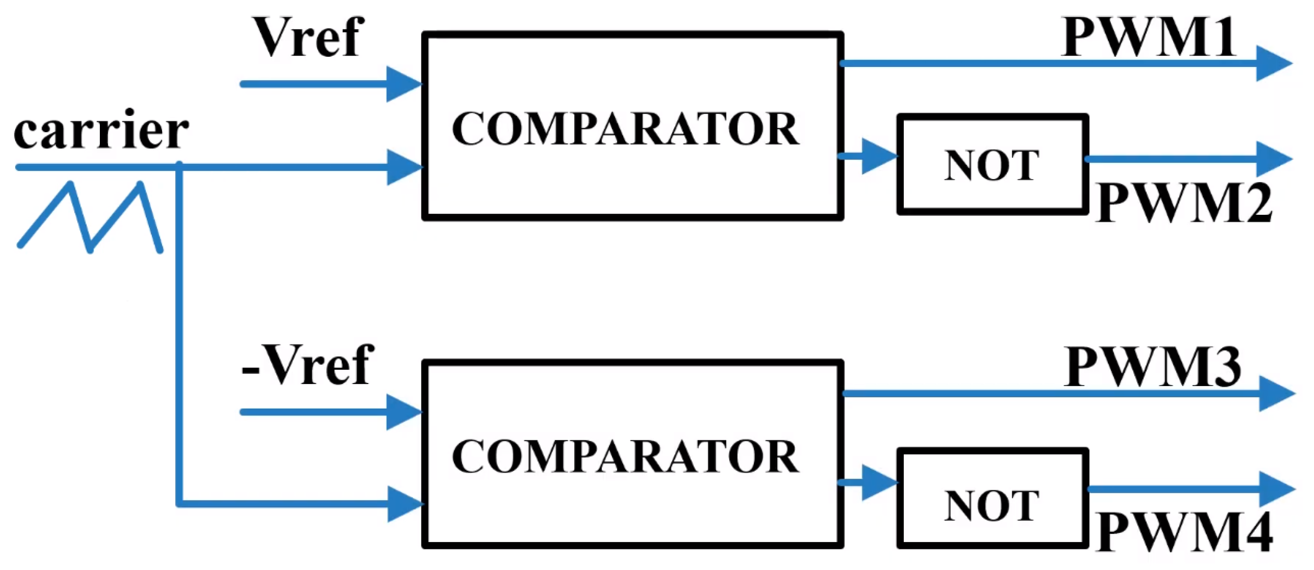
Figure 15.
Simulation of the load and the electrical network (Own elaboration.
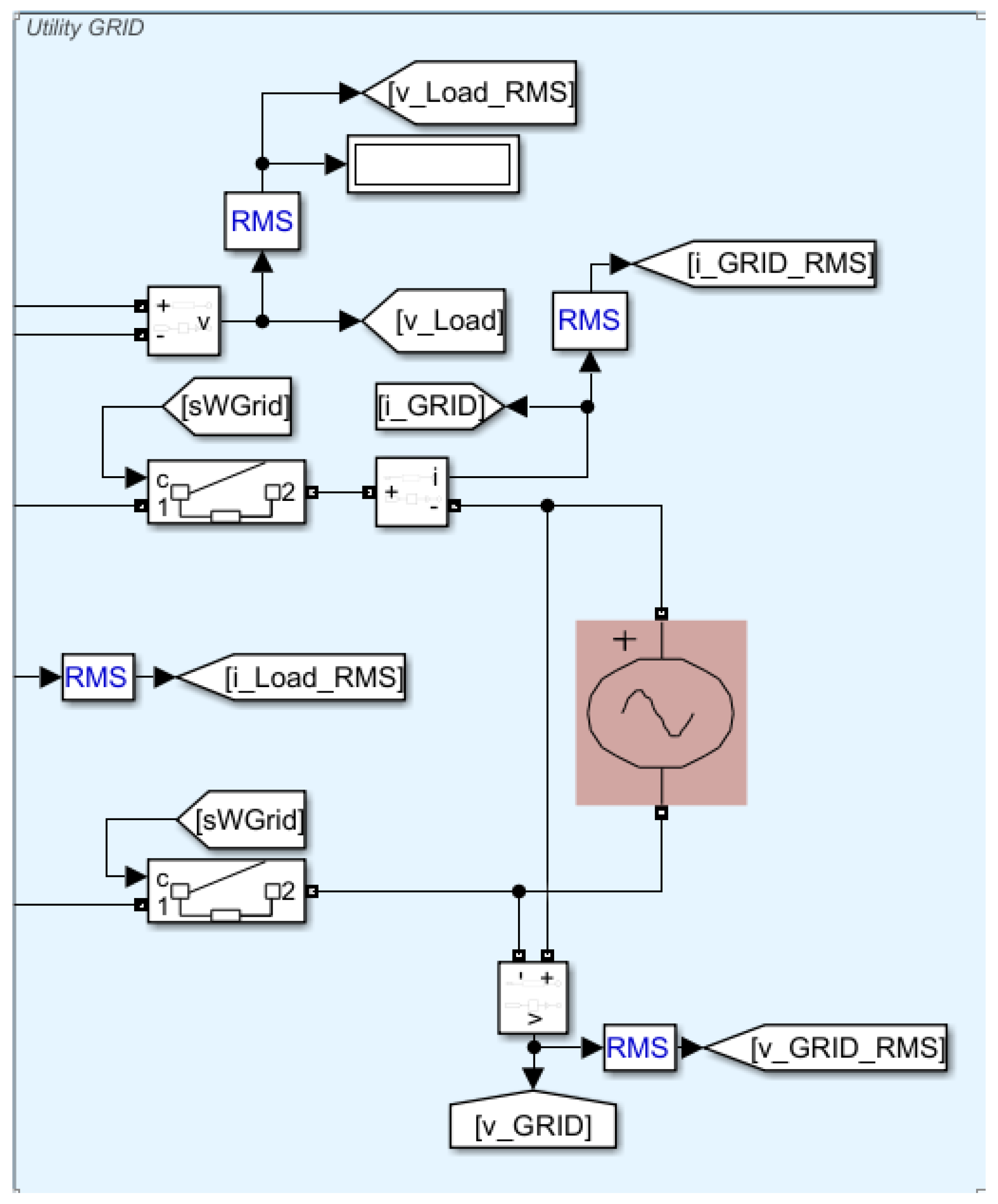
Figure 16.
OPC Server and Matlab communication architecture (Own elaboration).
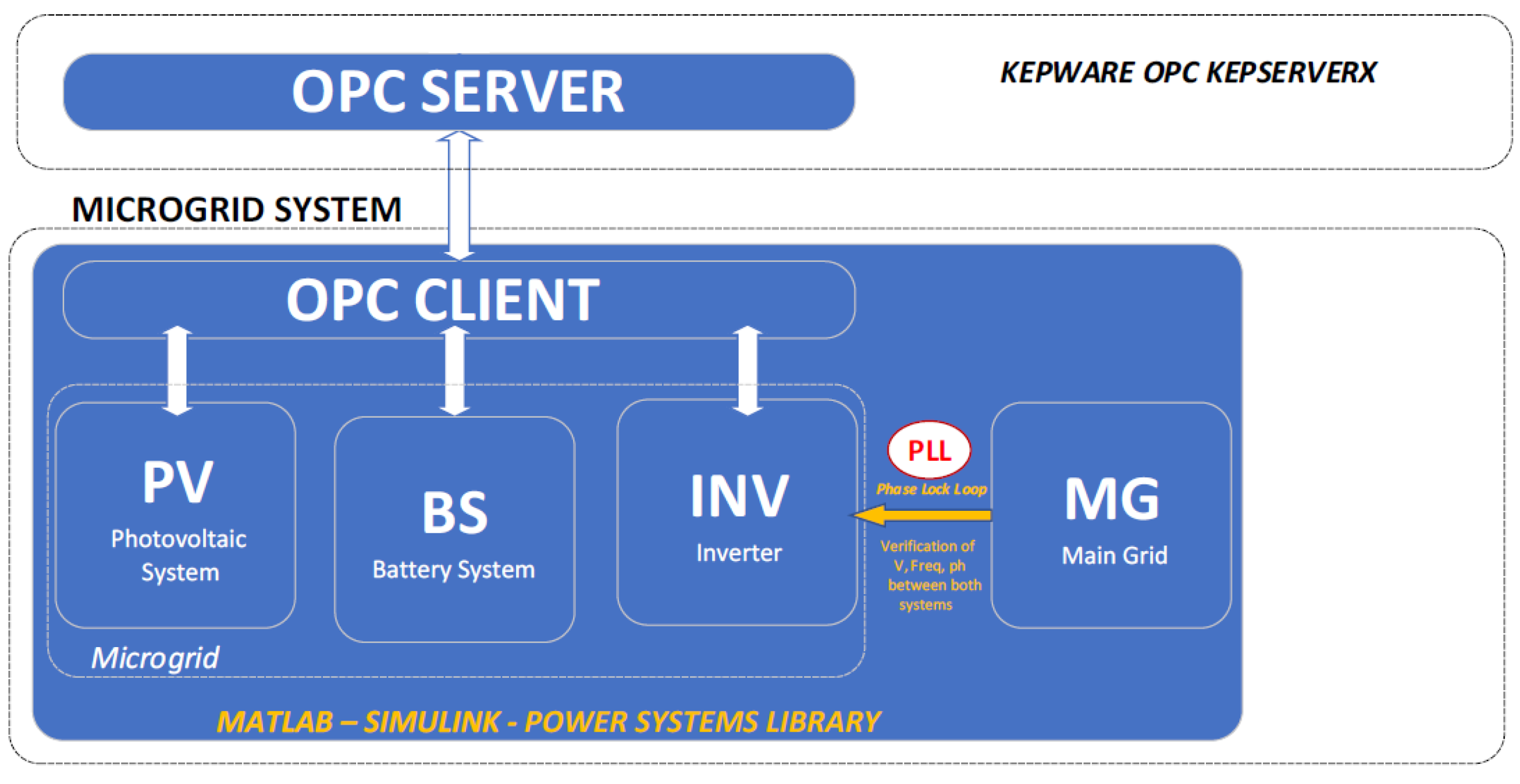
Figure 17.
Matlab OPC client configuration.
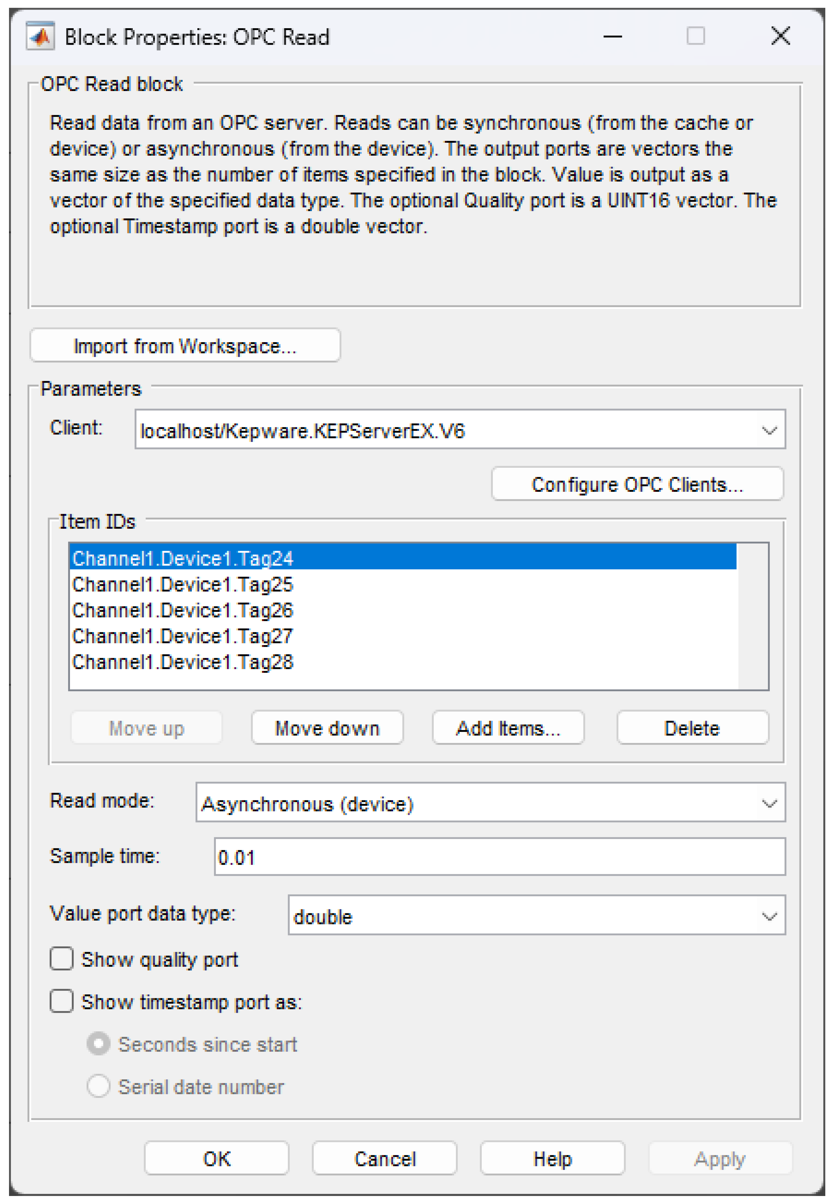
Figure 18.
Tag creation and configuration window (Own creation).
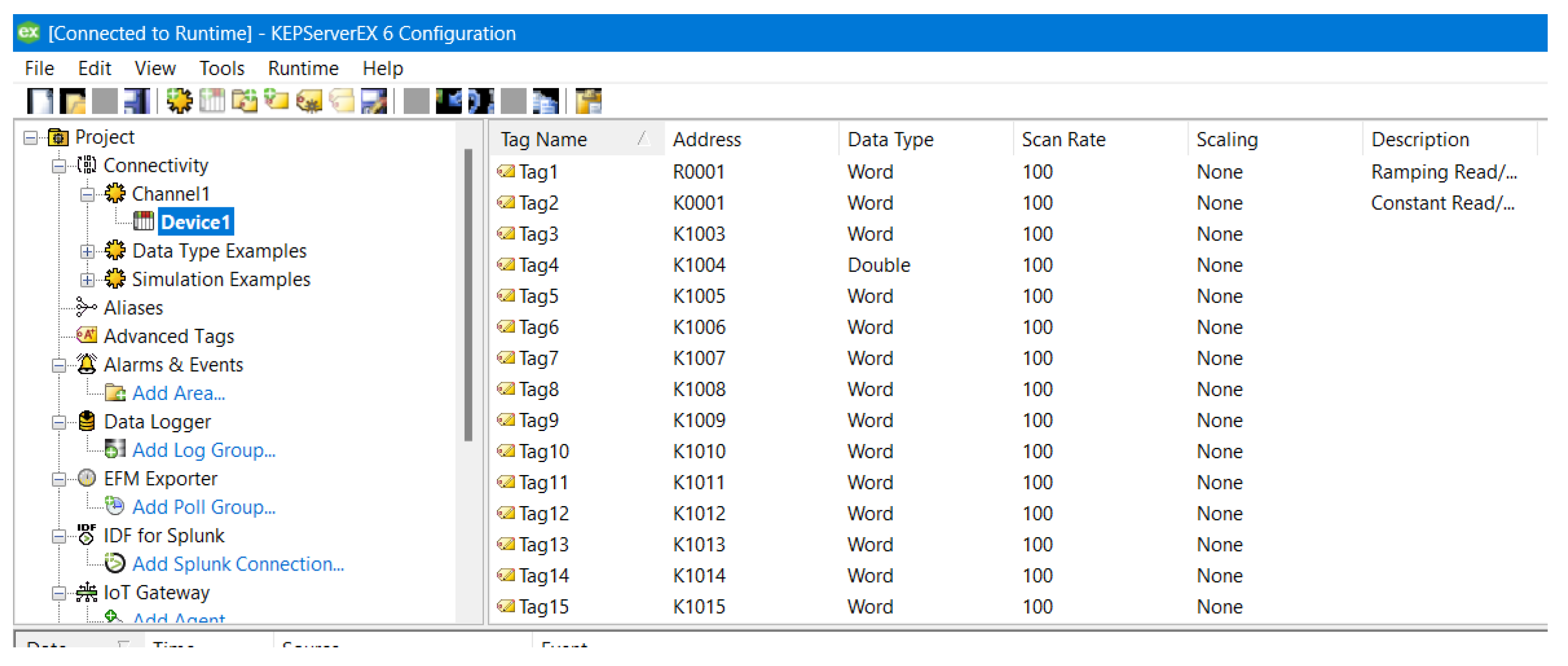
Figure 19.
OPC communication block.
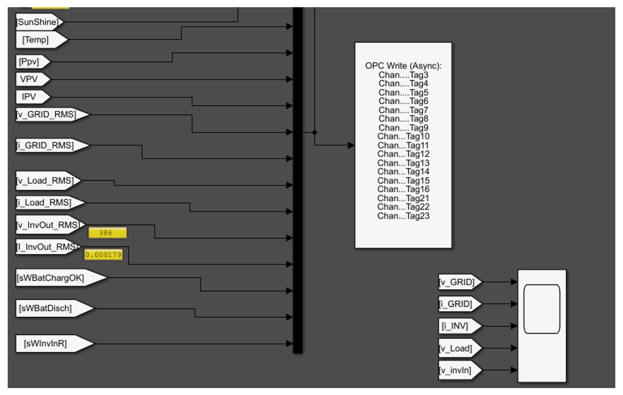
Figure 20.
OPC – RapidSCADA client configuration window (Own elaboration).
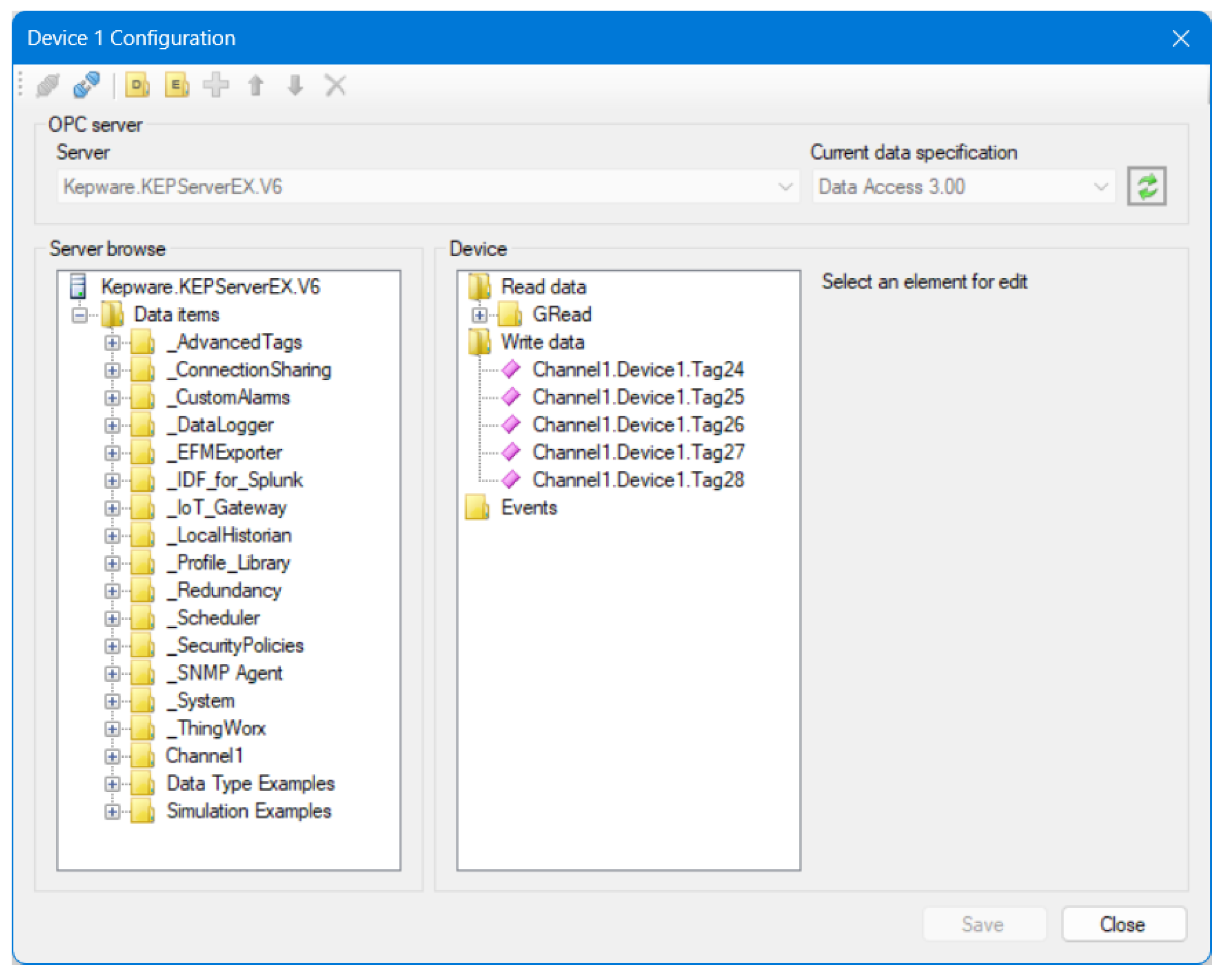
Figure 21.
Device creation window.
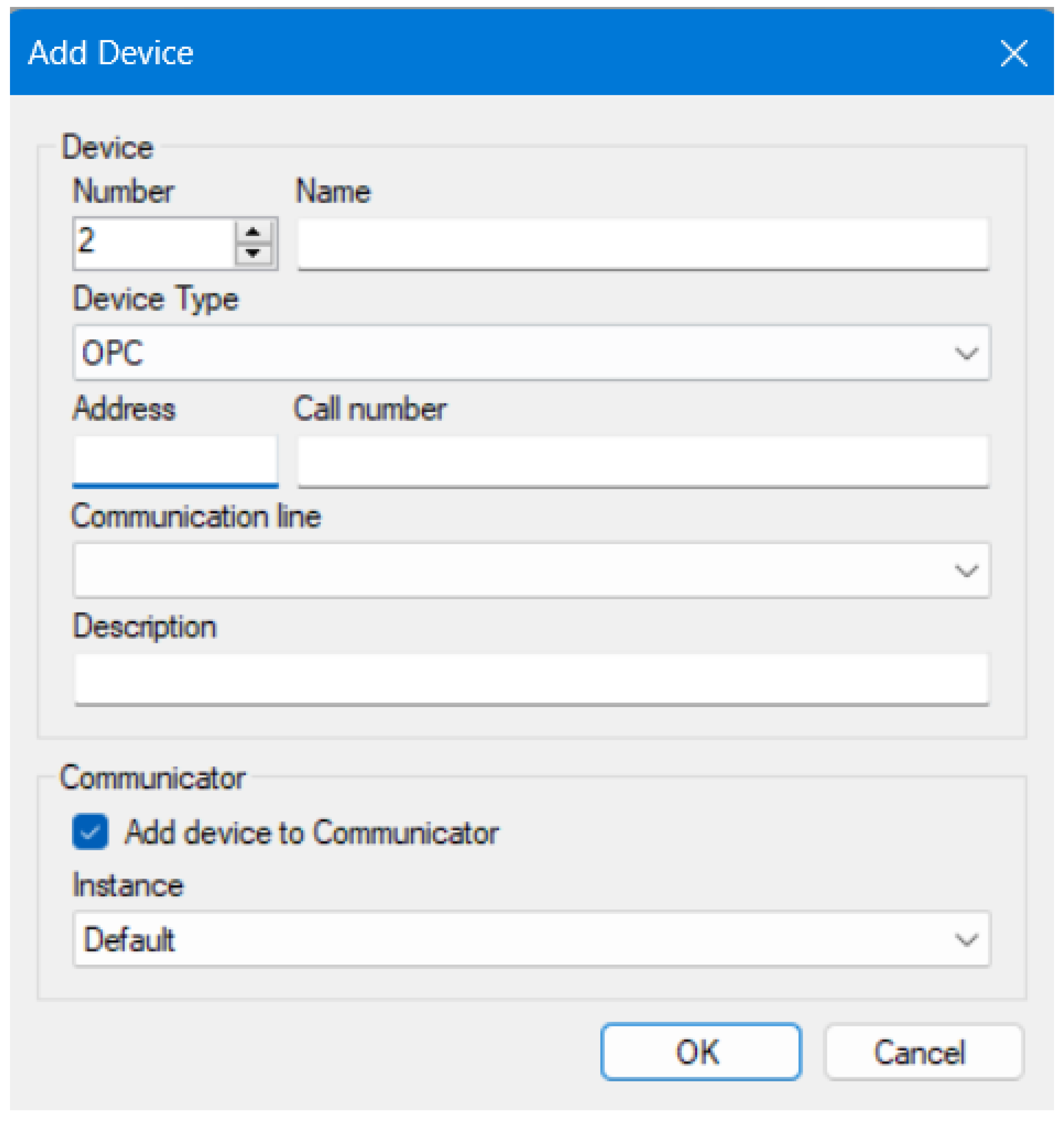
Figure 22.
Tags or signals configuration window (Own elaboration).
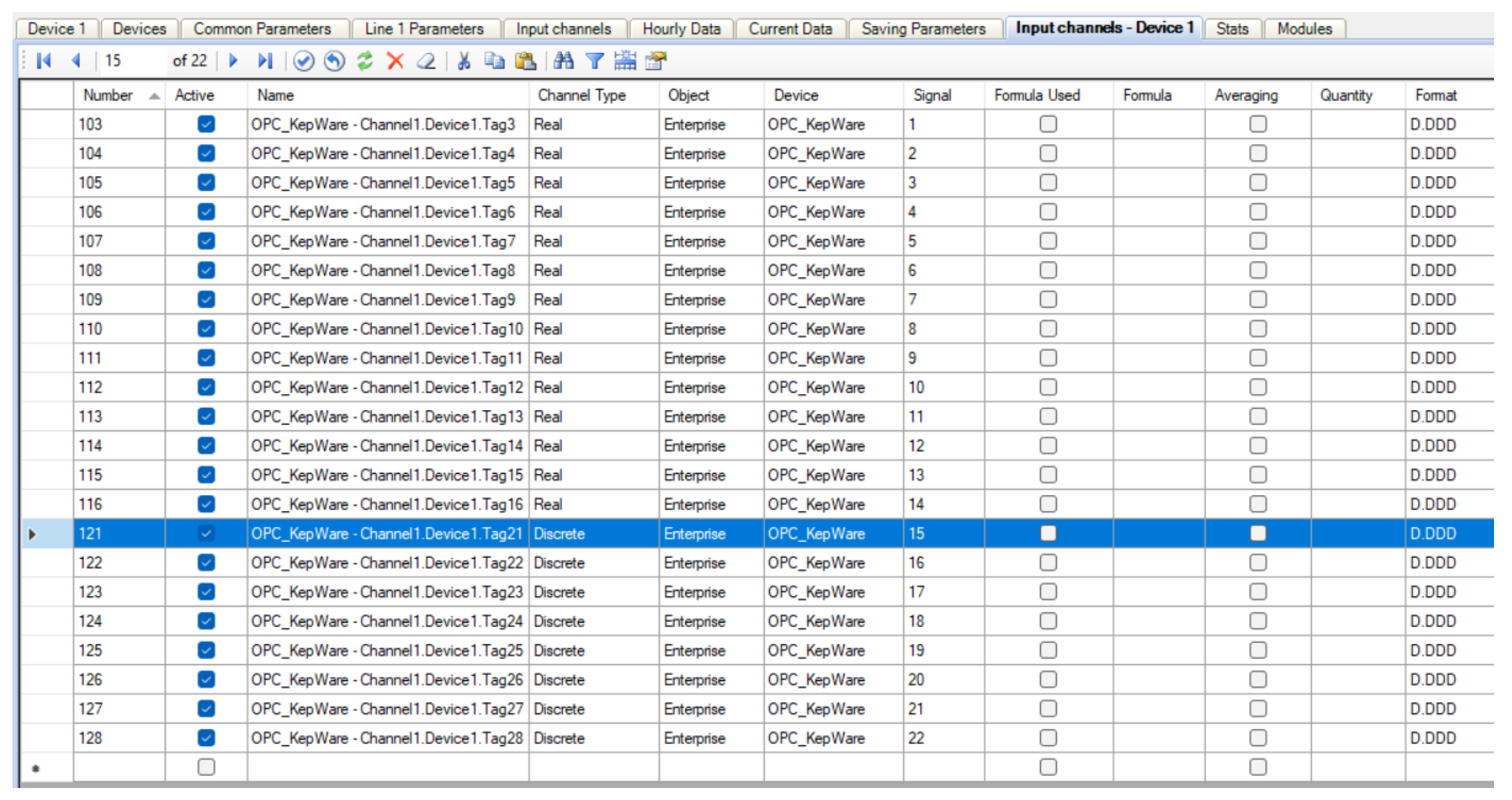
Figure 23.
Data table, Rapid SCADA deployment (Own elaboration).
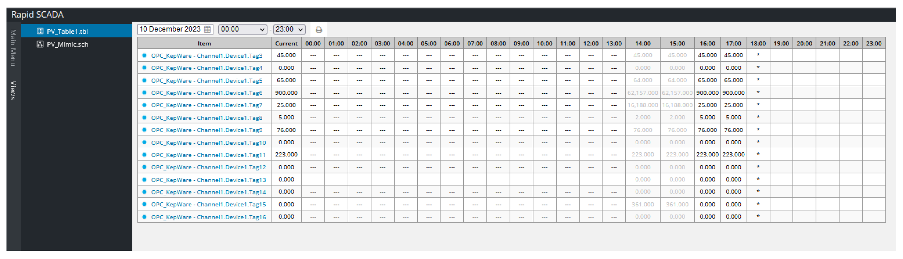
Figure 24.
Rapid Scada Server (Own elaboration).
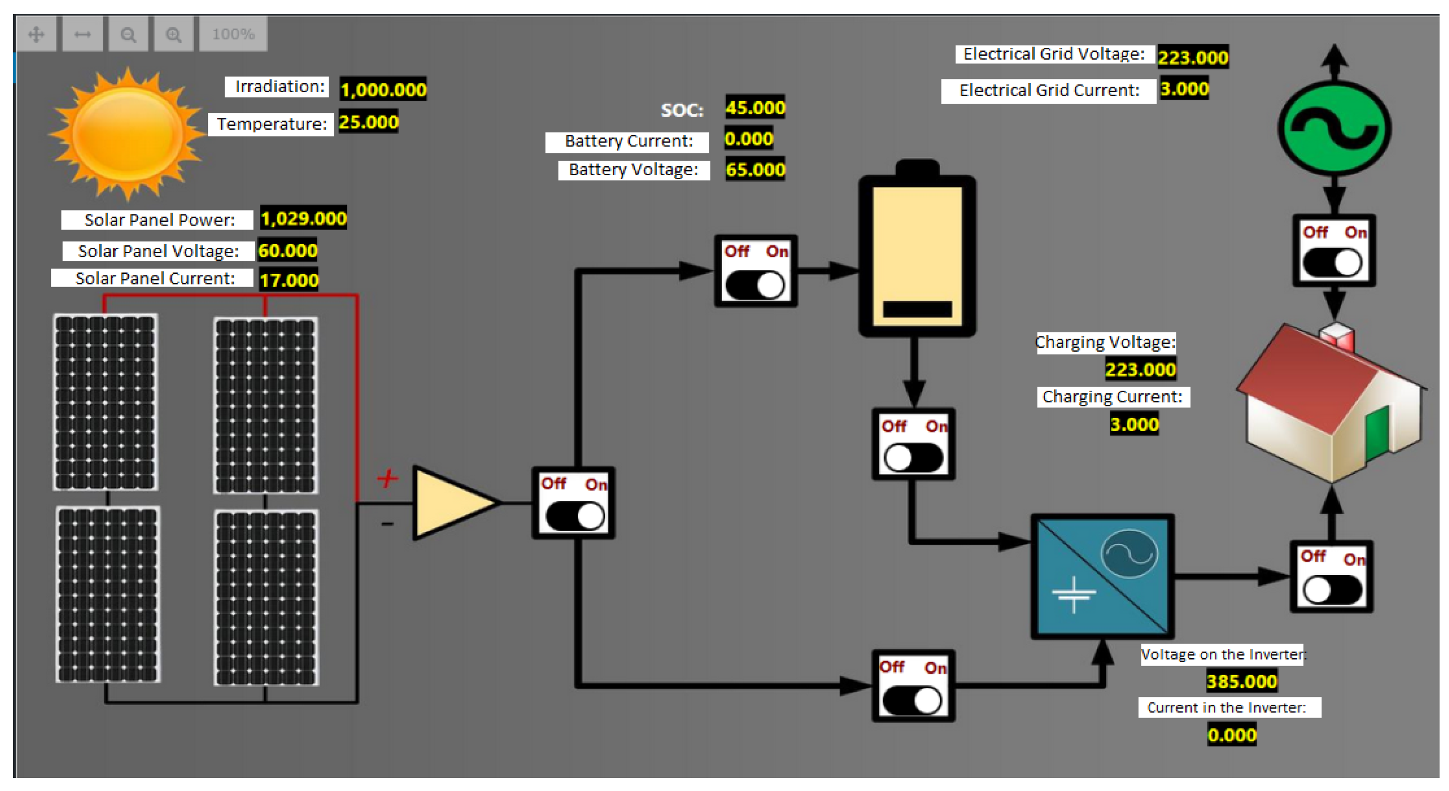
Figure 25.
Alias Configuration for MSSQL Instance.
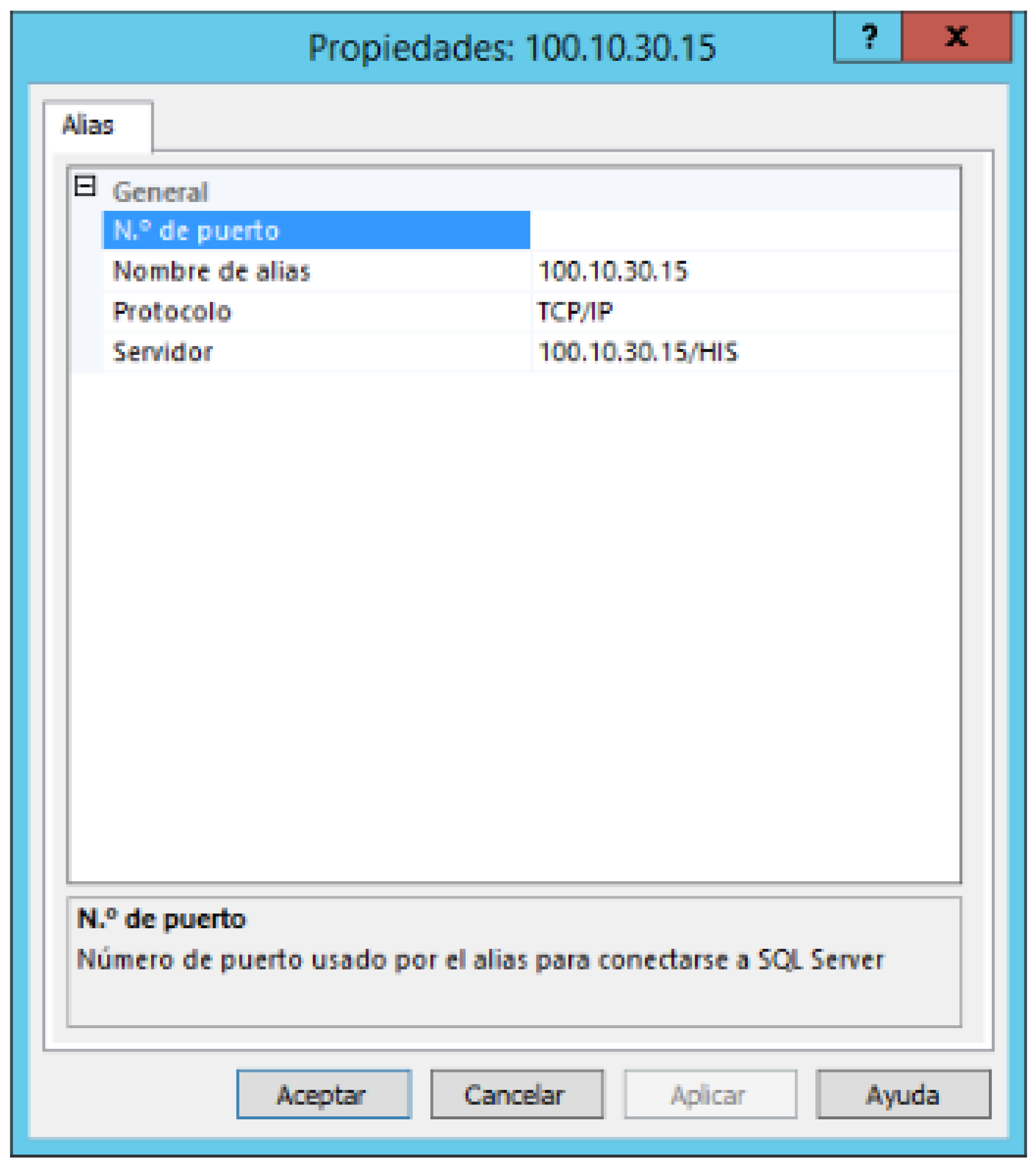
Figure 26.
MS SQL history table.
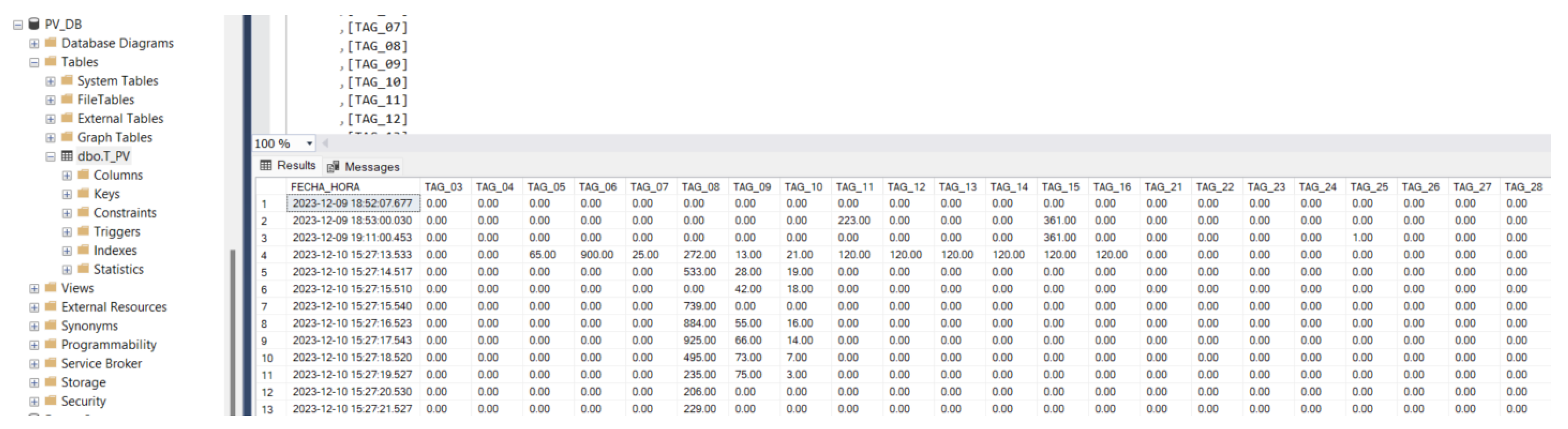
Figure 27.
RapidSCADA writing module configuration in Database (Own elaboration).
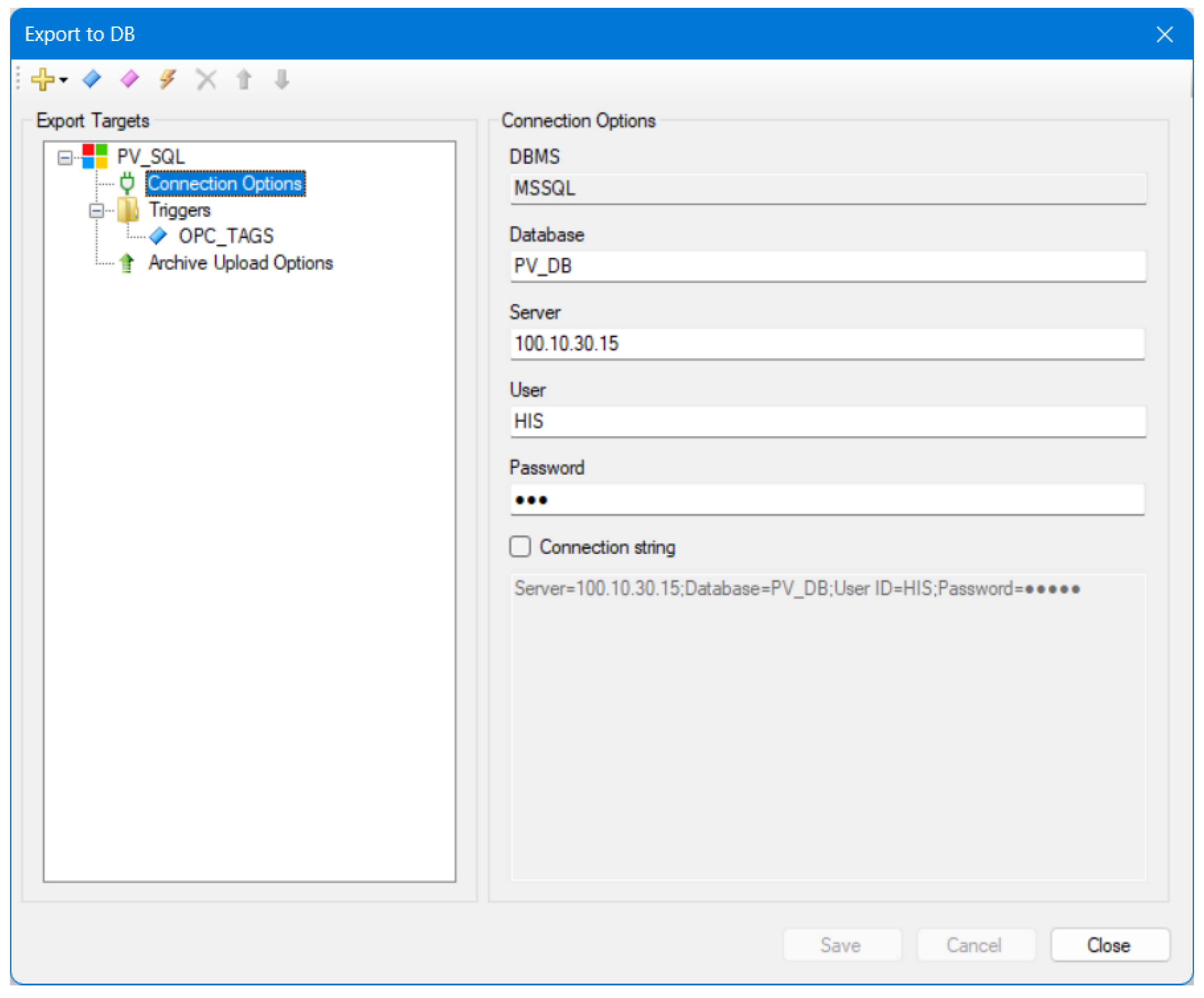
Figure 28.
Data insertion screen in SQL instance (Own elaboration).
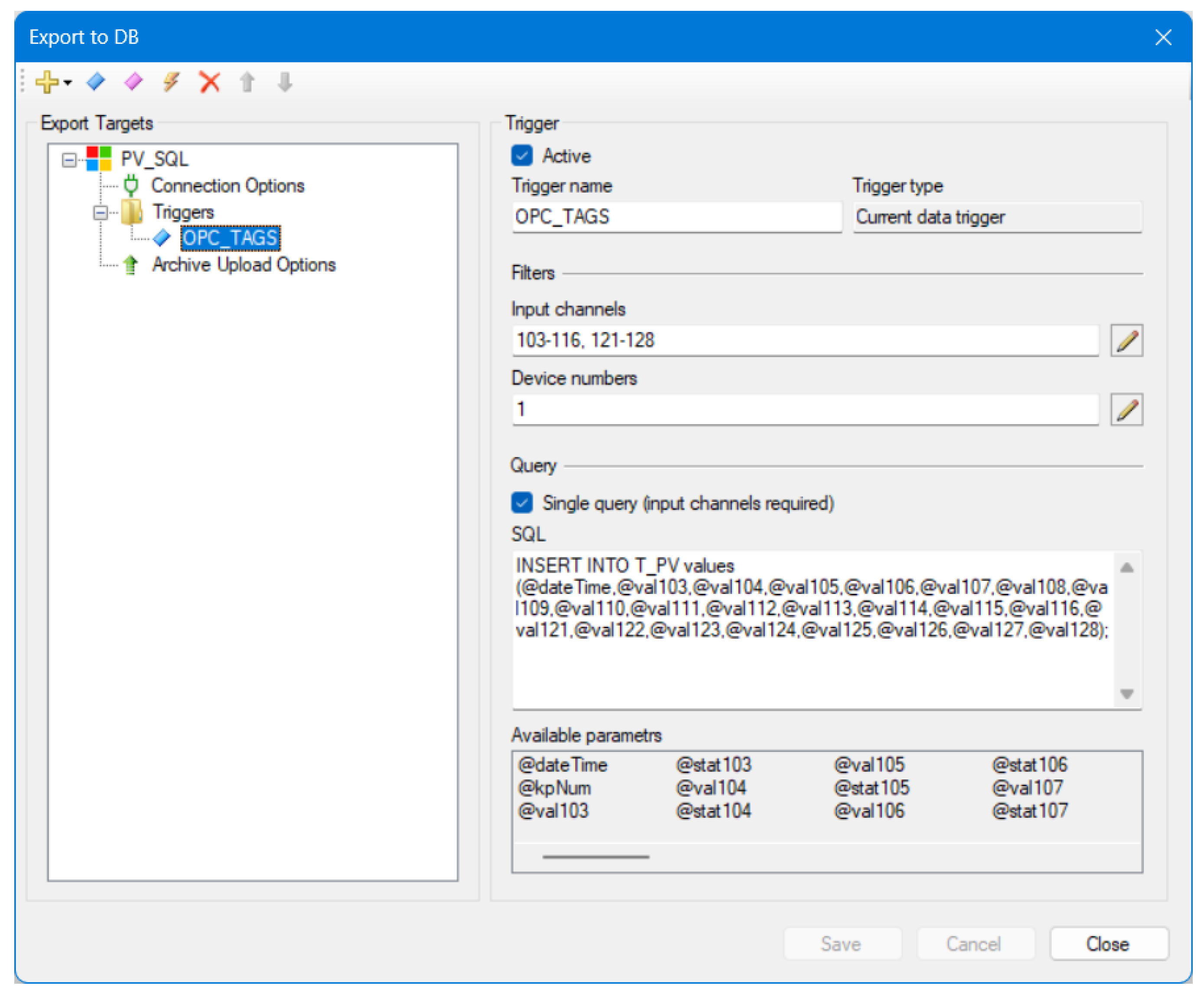
Figure 29.
Data writing configuration in RapidSCADA.
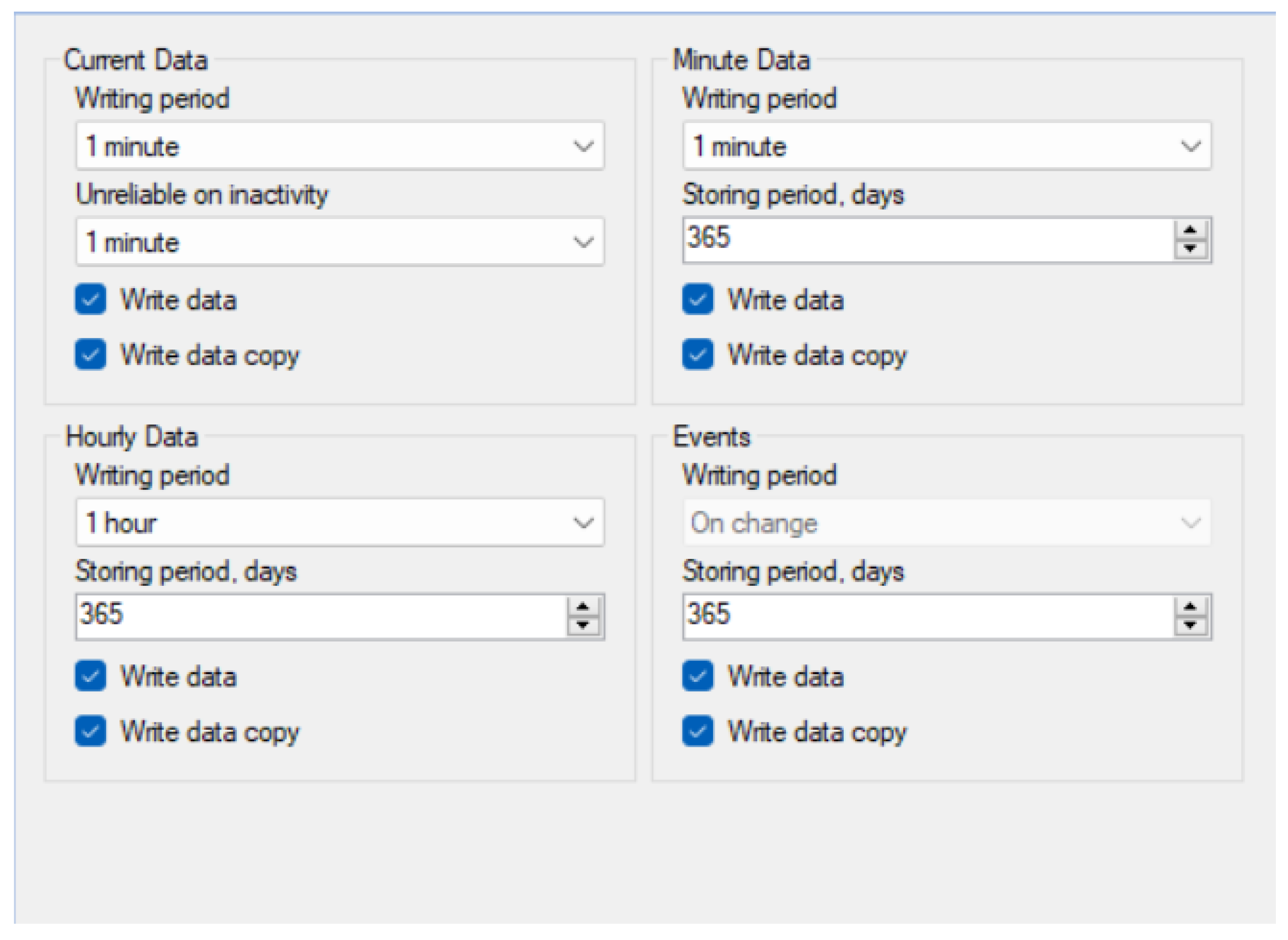
Figure 30.
Reporting Services configuration window (Own elaboration).
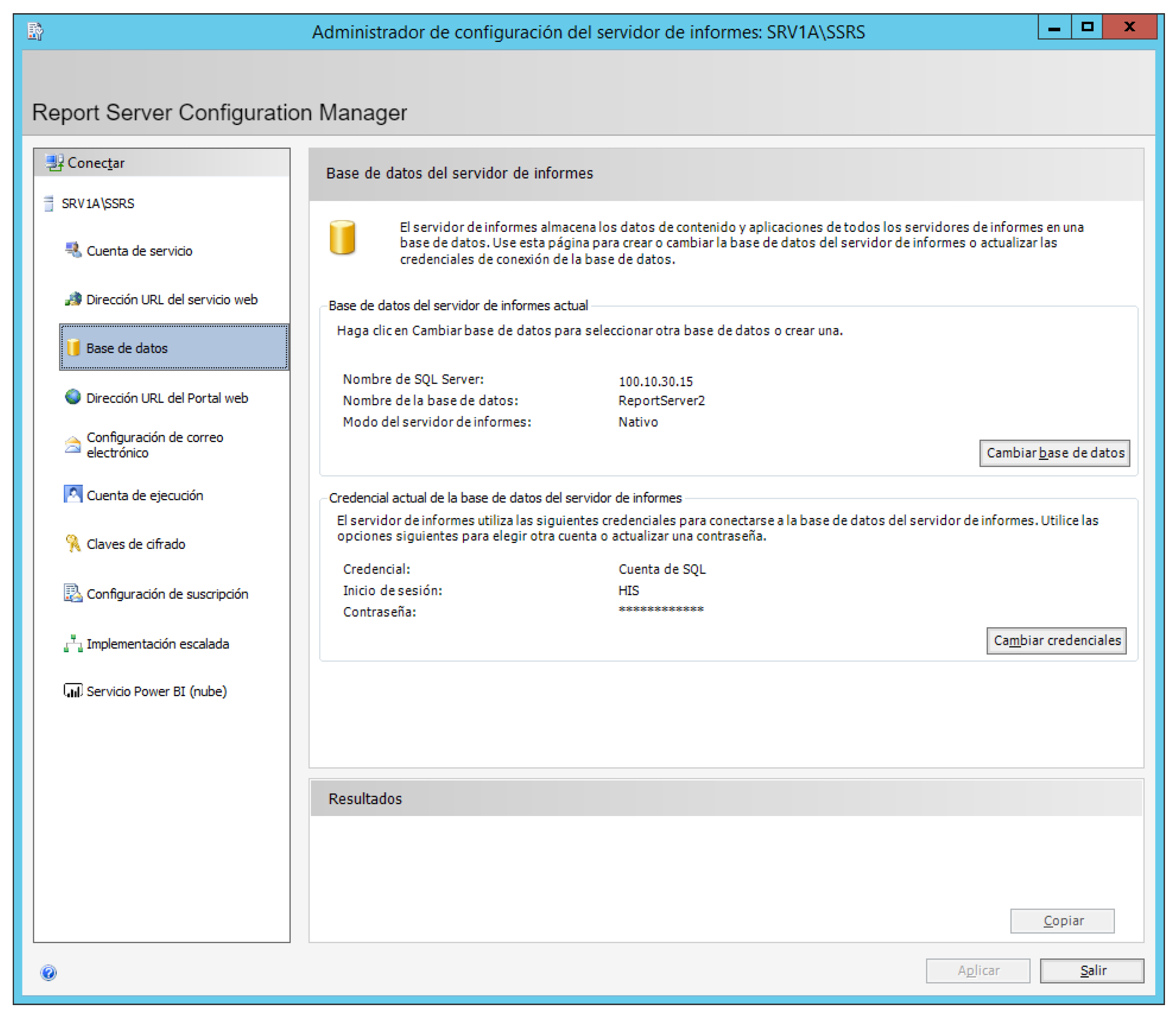
Figure 31.
Reporting Services welcome screen (Own elaboration).
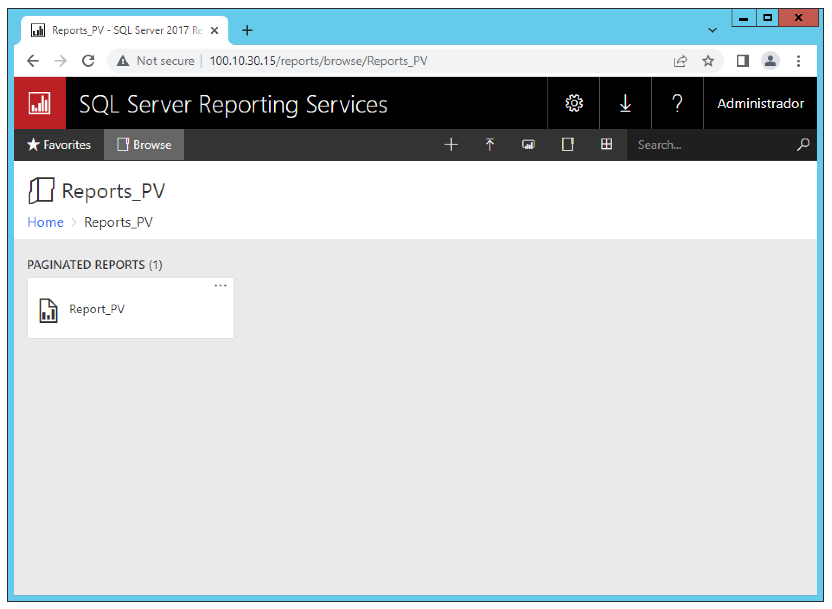
Figure 32.
Reporting Services configuration window for access to the SQL server (Own elaboration).
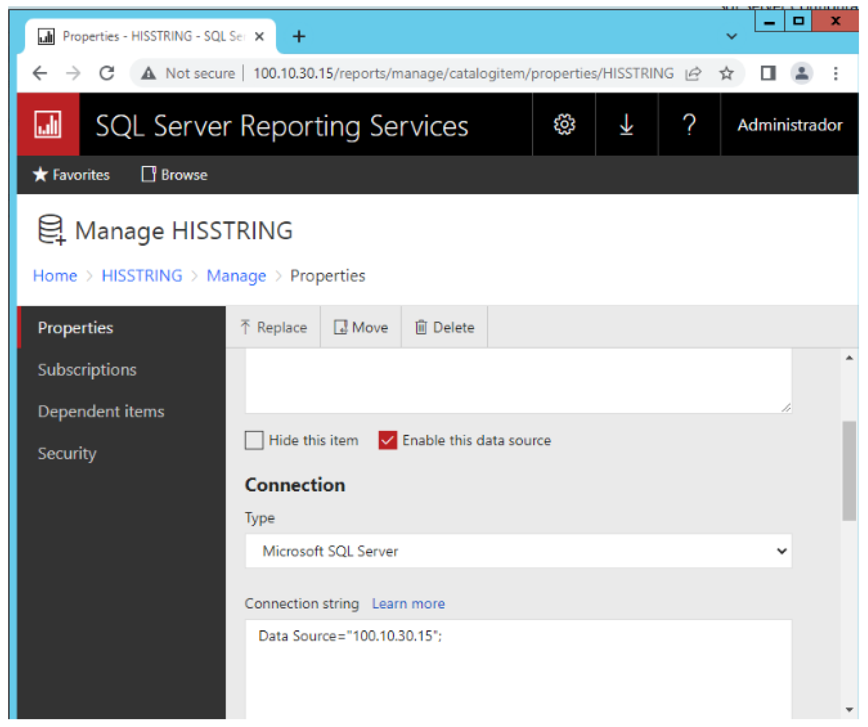
Figure 33.
Report Builder configuration window (Own elaboration).
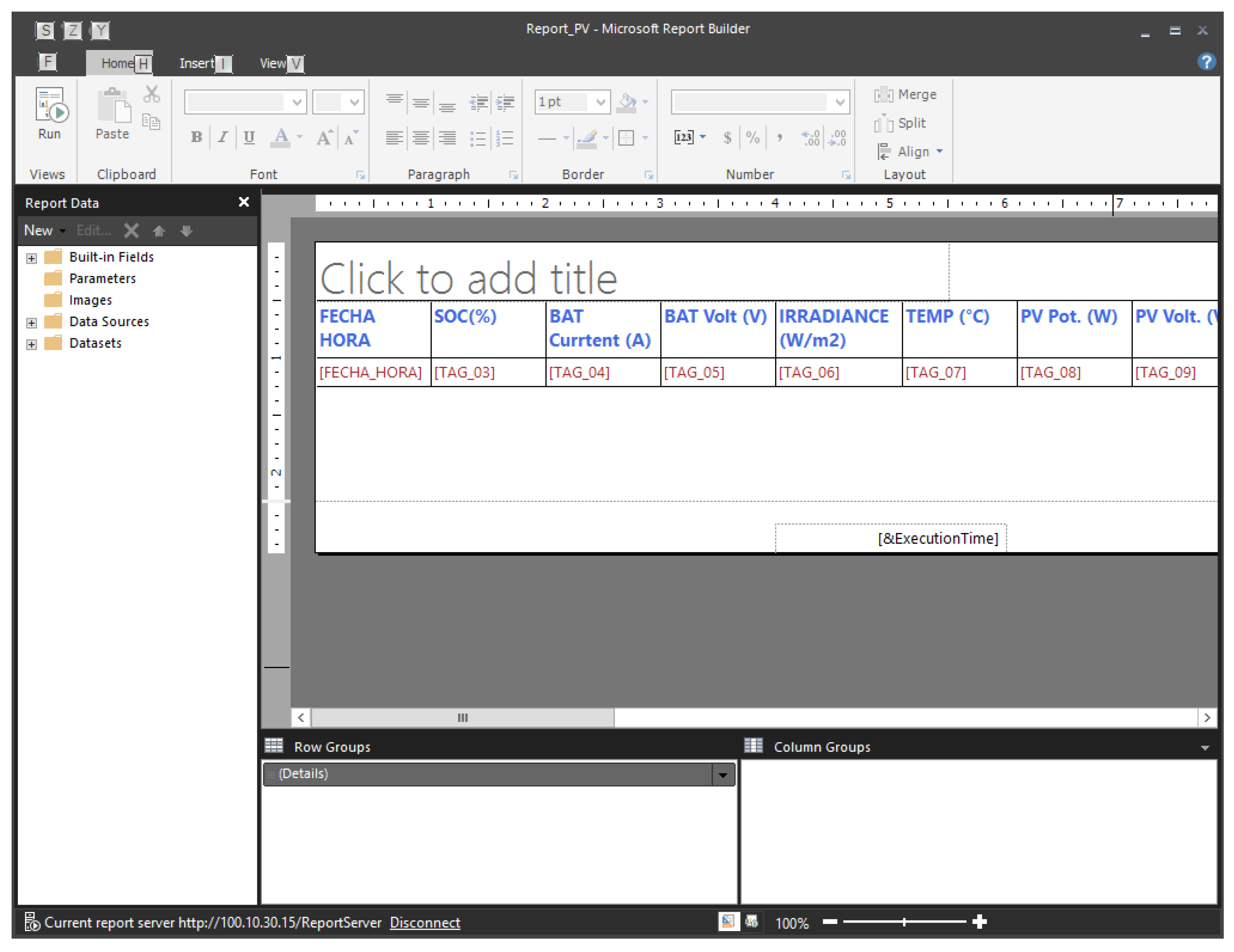
Figure 34.
Data report via web - (Own elaboration).
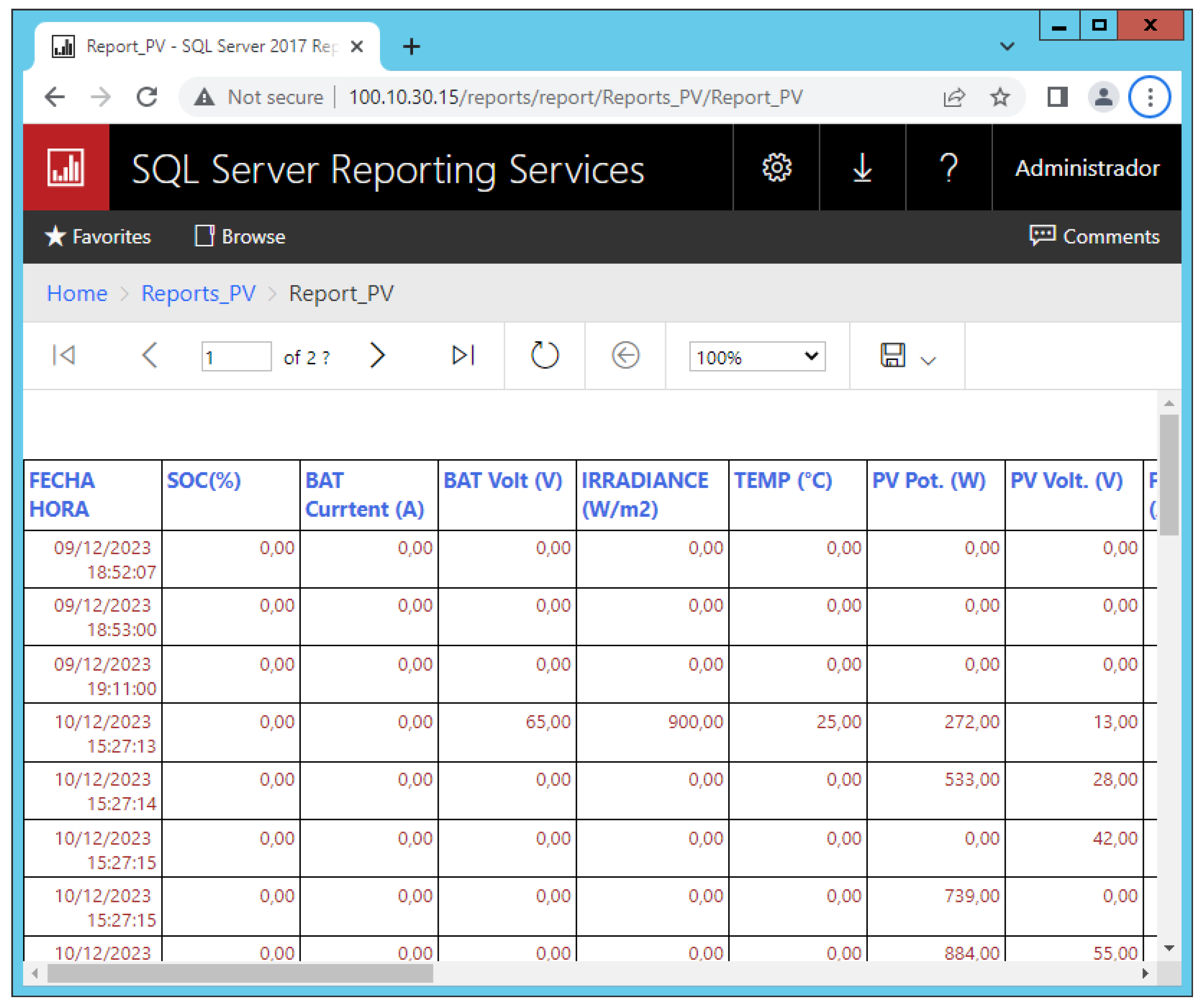

Table 1.
Housing characterization.
| Ambient | Quantity |
| Kitchen | 1 |
| Bedrooms | 2 |
| Bathrooms | 2 |
| Courtyards | 1 |
| Garage | 1 |
| Study room | 1 |
| Laundry | 1 |
| Living room dining room | 1 |
Table 2.
Most frequently used artifacts.
| Type | Description |
| Refrigerator | |
| Electric cooker | |
| Rice cooker | |
| Microwave Kiln | |
| 29” TV | |
| 29” TV |
Table 3.
Standard conditions for the solar panel arrangement.
| Type | Description |
| Irradiation standard | |
| Maximum power | |
| Voltage at maximum power point | |
| Current at maximum power point |
Table 4.
Worst-case conditions for the solar panel arrangement.
| Type | Description |
| Worst-case irradiation condition | |
| Maximum power | |
| Voltage at maximum power point | |
| Current at maximum power point |
Table 5.
Analog signals (own elaboration).
| TAG | Sign | Unit | Type | Commentary |
| 1 | SOC (State of Charge) - Battery | % | Read | Battery charge status |
| 2 | Voltage - Battery | V | Read | Voltage (at the battery) |
| 3 | Current - Battery | A | Read | Current (in battery) |
| 4 | Solar Radiation | W/m2 | Read | Solar radiation |
| 5 | Temperature | °C | Read | Temperate |
| 6 | Power - Solar Panel | W | Read | Power (at panel output) |
| 7 | Voltage - Solar Panel | V | Read | Voltage (at panel output) |
| 8 | Corriente - Solar Panel | A | Read | Current (At panel output) |
| 9 | Voltage - Utility | V | Read | Voltage (At the power grid output) |
| 10 | Current - Utility | A | Read | Current (At the power grid output) |
| 11 | Voltage - House | V | Read | Voltage (At the entrance of the home/residence) |
| 12 | Current - House | A | Read | Current (At the entrance of the home/residence) |
| 13 | Voltage - Inverter | V | Read | Voltage(At inverter output) |
| 14 | Current - Inverter | A | Read | Current (At inverter output) |
| 15 | Energy consumed | KwH | Read | KiloWatt-Hour (At the entrance of the home/residence) **Calculated from the power and the elapsed time |
| 16 | Injected energy | KwH | Read | KiloWatt-Hour (At the entrance of the home/residence) ** Calculated from the power and the elapsed time |
Table 6.
Digital signals (own elaboration).
| TAG | Sign | Unit | Type | Commentary |
| 17 | MCB Position - Panel | ON/OFF | Read/Write | MCB Mini Circuit Breaker |
| 18 | MCB Position - Battery Input | ON/OFF | Read/Write | MCB Position - Battery Input |
| 19 | MCB Position - Battery Output | ON/OFF | Read/Write | MCB Position - Battery Output |
| 20 | MCB Position - Inverter Input - Battery | ON/OFF | Read/Write | MCB Position - Inverter Input - Battery |
| 21 | MCB Position - Inverter Input - Solar Panel | ON/OFF | Read/Write | MCB Position - Inverter Input - Solar Panel |
| 22 | MCB Position - Inverter Output | ON/OFF | Read/Write | MCB Position - Inverter Output |
| 23 | MCB Position - Power Grid | ON/OFF | Read/Write | MCB Position - Power Grid |
Disclaimer/Publisher’s Note: The statements, opinions and data contained in all publications are solely those of the individual author(s) and contributor(s) and not of MDPI and/or the editor(s). MDPI and/or the editor(s) disclaim responsibility for any injury to people or property resulting from any ideas, methods, instructions or products referred to in the content. |
© 2024 by the authors. Licensee MDPI, Basel, Switzerland. This article is an open access article distributed under the terms and conditions of the Creative Commons Attribution (CC BY) license (http://creativecommons.org/licenses/by/4.0/).
Copyright: This open access article is published under a Creative Commons CC BY 4.0 license, which permit the free download, distribution, and reuse, provided that the author and preprint are cited in any reuse.


