
Submitted:
02 May 2025
Posted:
07 May 2025
You are already at the latest version
Abstract
Parallel robots present advantages over serial robots for applications that benefit from low moving masses and energy consumption, while a low ratio of workspace to installation space is tolerable. Many structures for parallel robots have been found theoretically, but only a limited part of them has been practically applied yet. To find the best robot for a given task, a database of all suitable robots has to be available to perform a combined structural and dimensional synthesis. The structural synthesis defines leg chains and determines the alignment of the legs’ coupling joints. The latter can be either seen as part of the dimensional synthesis as a variable in this otherwise continuous optimization problem or as part of the structural synthesis as a discrete property of a robot. As the robot’s end-effector degrees of freedom (DoFs) are influenced by this alignment, it is explicitly considered as part of the structural synthesis in this work. A geometric permutation gives all combinations of leg chains and alignments of base- and platform-coupling joints and assesses the resulting parallel robot’s DoFs by numeric evaluation in a dimensional synthesis. It creates a parallel-robot database that includes the degrees of freedom for symmetric, fully parallel robots with the motion patterns of three translational and zero to three rotational DoFs: 3T0R, 3T1R, 3T2R, and 3T3R. In total, 94, 61, 21, and 223 structures for the respective motion patterns were obtained, and some robots were found that had not yet been described in the literature. The proposed permutational and numeric approach presents an alternative to structural synthesis via computer algebra systems and is computationally feasible despite the high number of parallel-robot candidates. The database, published as open source, can be further used in a combined structural and dimensional synthesis to optimize all possible robots for a given task and select the best.
Keywords:
parallel robot
; parallel-kinematic machine
; structural synthesis
; geometric permutation
; coupling joint
1. Introduction
Parallel robots have a shorter history than serial robots [1,2,3]. Their wider deployment has been feasible since the 1990s, based on fundamental works in the 1980s [4]. Limiting factors for their development were the higher model complexity and the resulting much higher demands on control hardware. The most important structures were developed until the 1990s with the Gough-Stewart platform (hexapod), the Delta, and the Hexa robot. Numerous concepts for further robot architectures were created after that [1,3,5,6,7] but have not yet reached industrial dissemination except for single examples.
The structural synthesis of parallel robots determines the number and alignments of joints within kinematic chains, referred to as legs, which are connected in parallel to a mobile end-effector platform. Systematic mathematical frameworks like screw theory [5], the theory of linear transformations [6], and others take into account the higher complexity of parallel over serial robots. The dimensional synthesis determines numerical values for the parameters. Several authors have emphasized its significance for parallel-robot performance, noting that it is as crucial as structural synthesis: [8, p. 124], [9, p. 175], and [1, p. 25]. This distinguishes parallel from serial robots, where the dimensioning tends to be more intuitive. Since good dimensioning is necessary for all parallel-robot prototypes, many studies on the dimensional synthesis of single parallel robots have been performed [10].
The concept of combined structural and dimensional synthesis optimizes multiple structures before selecting one structure for detailed construction. It was first realized by [11] for a comparison of hexapod (6-UPS), HexaGlide (parallel-rail 6-PUS), and Linapod (vertical 6-PUS) and by [9] for comparing Delta (3-RUU) and TriGlide (3-PUU). The concept was pursued systematically by [12] for three-DoF translational parallel robots. There, a permutation of three different alignments of base-coupling joints and 16 leg chains has been investigated, which resulted in 26 parallel robots. The platform-coupling joints have not yet been explicitly considered, even though multiple possibilities affect the performance. The limiting assumptions of earlier works regarding the number of leg joints (limited to three), the selected platform DoFs (3T or 3T3R), the considered coupling-joint alignments (three for base coupling), and thereby, the number of structures can now be lifted, facing increased computational capabilities and efficient algorithms. More unexpected solutions can then be found within the combined synthesis as more structures can be considered, which raises the potential for selecting parallel robots with better performance.
Including not only well-known [9,11] or a few manually selected and modeled structures [12] into the combined synthesis requires a database of parallel robots that is integrated into a software framework for combined synthesis. The database should include the structural properties of the robots as well as analytic models for kinematics and dynamics to compute their performance in the dimensional synthesis. Despite several concepts and contents for such a database having been published [5,6,12,13], the implementations of the robot databases themselves remain proprietary, which prevents using it directly in an automated combined structural and dimensional synthesis.
This database is created by the structural synthesis presented in this paper. The approach follows the idea of geometric permutation, chosen from the viewpoint of the later dimensional synthesis by separating continuous and discrete variables of the optimization problem presented by the robot synthesis. The structural synthesis uses the dimensional synthesis from [10] for the numerical evaluation of robot structures instead of the analytic approach mainly pursued in the literature. In a subsequent step, the database is used by the dimensional synthesis to provide many suggestions for optimized parallel robots (PRs) for given tasks, which are discussed as case studies in [10]. Therefore, both papers should be regarded as one framework for the combined structural and dimensional PR synthesis.
The contributions of this paper are:
- a method for structural synthesis of parallel robots that integrates into the concept of combined structural and dimensional synthesis,
- a comprehensive and structured overview of all parallel robots that were found with the method, with illustrations of some examples, and
- a validation of the approach by comparison of the resulting robots with the literature.
The presented methods [14] and the resulting robot database [15] are available as open source, which was first published together with previous publications [10,16].
The remainder of the paper is structured as follows. Section 2 introduces the state of the art of the structural synthesis of parallel robots. The contributed synthesis method via geometric permutation is presented in Section 3, followed by the obtained results in Section 4 and a discussion in Section 5.
2. Related Work: Methods for Structural Synthesis of Robots
The structural (or type) synthesis determines the kinematic structure (order and type of links and joints) of a robot manipulator [17] by virtually assembling the robot from basic components. The foremost goal of the synthesis is to create an articulated mechanism with the required degree of freedom at an end-effector link. Other objectives that can be addressed within the structural synthesis are to achieve a desired workspace shape or distribution of singularities.
The first designs for robot manipulators followed intuitive approaches or existing principles, such as anthropomorphic arm-like serial manipulators or the Gough-Stewart platform for parallel manipulators. Analysis of these structures represented a significant part of the work in robotics research. The systematic synthesis was investigated in parallel and partly delayed to the respective technology’s dissemination. A systematic overview of all possible kinematic structures is not necessary for efficiently deploying basic structures. Still, it allows for finding better solutions for specific tasks and provides further insights into the fundamentals of mechanism and machine theory.
In the following, a brief state-of-the-art review of the synthesis of serial-kinematic chains is given in Section 2.2, as this presents a prerequisite for the synthesis of parallel robots, which is the subject of Section 2.3. For the sake of brevity, for fundamentals, the reader is referred to corresponding textbooks (e.g., [1,5,6,18]) and monographs (e.g., [8]). Only a brief summary of the preliminaries is given in Section 2.1, which is derived from the author’s previous works [19,20]. The terminology is chosen according to the International Federation for the Promotion of Mechanism and Machine Science (IFToMM), replicated in [6, p. 12 ff]. The design rules for parallel robots are briefly summarized in Section 2.4, and examples from the literature are given in Section 2.5.
2.1. Preliminaries: Kinematic Model of Parallel Robots
A general approach for a kinematics model of parallel robots is reported in introductory textbooks [1,6,21] and serves as a reference for an extension regarding the requirements of the robot synthesis pursued in this paper. The considered parallel robot consists of m legs with joint coordinates each, connected at a moving platform. All joints are modeled as single-DoF, i.e., universal and spherical joints are split into virtual single revolute joints. Additionally to the active joints explicitly all passive joints , including the platform-coupling joints, are part of the coordinates of leg i. All joint coordinates of the parallel robot are stacked in the vector , and all active joints are assembled in the vector , without loss of generality assuming one actuation per leg.
A sketch of the assembly of the robot’s leg chains (corresponding to solving the IKP) is depicted in Figure 1 with the necessary coordinate systems for kinematic modeling adapted from [21], including a robot base frame , leg-chain base frames , and coupling frames at the platform and at the distal ends of the leg chains.
2.1.1. Leg chain
By assuming the cut coupling-joint frames to be the chain’s end-effector frame, a leg chain can be mathematically described by serial-chain kinematics from standard textbooks. The pose of a frame is expressed with the minimal coordinates containing the Cartesian position and orientation (as three Euler angles). The analytic Jacobian of a leg chain provides the velocity relation . The twist vector includes linear and angular velocities of the frame. The geometric Jacobian of a leg is obtained by and provides the relation .
2.1.2. Parallel Robot
The relation between joint coordinates of the parallel robot and its platform coordinates for the desired frame is established with the kinematic-constraint equations. In parallel-robot synthesis, the purpose of the differential formulation is to determine the mobility of the moving platform. In [6], an extension of this approach on the velocity level, including coupling-frame angular velocities, is called the theory of linear transformations.
The translational constraint is defined by the vector loop from the robot base frame to the desired platform frame and to the actual platform frame as
 The frame results under the assumption , i.e., the cut coupling joint frame is aligned to the corresponding cut frame on the platform, as sketched in Figure 1. The series of frame rotations then is . One of the frames or could be omitted in the equations in principle, but they are kept for consistency with other possible constraint formulations, e.g., described in [10]. Furthermore, this demarcates the parts for serial and parallel robots.
The dependency on all joint coordinates, including distal ones, is visible by the term . This implies that the platform is now part of the last link of the considered leg chain. The full kinematic constraints have to be considered, including the rotational part
 which is needed to generate enough equations for an invertible matrix in the differential equations. The conversion from rotation matrix to Euler angles (specifically, Tait-Bryan angles) is denoted by . The constraints contain the deviation between the desired end-effector frame expressed with and the actual robot end-effector frame expressed with (from the perspective of leg chain i). The inverse-kinematics problem is then solved by using the Newton-Raphson algorithm for finding the for .
2.1.3. Differential Relation
Time-differentiation of the constraints and demanding equality to zero gives
which leads to the full inverse Jacobian of the parallel robot
It relates the velocities of all joints and the platform . The matrix is termed inverse due to the connection to the inverse of the manipulator Jacobian . It is no inverse in the mathematical sense since it is rectangular, and, therefore, the matrix does not exist. The selection matrix extracts rows corresponding to the velocity of the actuated joints by
giving also the inverse analytic Jacobian of the parallel robot. This equation presents a more general approach to obtaining the matrix than the classical constraints formulation since it does not rely on the elimination of passive-joint coordinates.
The model presented above can be used for parallel robots with full mobility (three translational and three rotational degrees of freedom, 3T3R DoFs) and arbitrary leg chains. Other cases, such as 3T, 3T1R, and 3T2R platform motion, require a modification of the approach (visible in Figure 1 by the relation of the second leg chain to the first one and not to the platform), as discussed in [20,22], which is omitted here for brevity.
2.2. Structural Synthesis of Serial-Kinematic Chains
The synthesis of serial robot structures (or serial-kinematic chains that can be part of a parallel robot) is based on the forward-kinematics relation of serially connected links and joints. The degrees of freedom of the chain result directly from the joint DoFs. The Cartesian DoF of the chain’s end effector can be determined by its Jacobian, i.e., the differential relation of joint and endpoint velocities. The reasoning for a parallel-robot leg chain is the same as for a serial-chain robot but with the terminology coupling-joint frame instead of end-effector frame. Therefore, the structural synthesis for serial-chain robots can also be used for the synthesis of parallel-robot leg chains.
In the late 1980s, fundamental works on the synthesis of serial-chain robots have been published. In [23], the synthesis is based on the separation of the kinematic chain into the positioning sub-chain (arm) and orientation sub-chain (wrist) of the end effector. Other authors, e.g. [24], found similar results, as cited in [25]. A permutation of possible joint alignments was performed for both axes groups. Equivalent structures (structural graphs describing the same mechanism, termed isomorphisms, cf. [1, p. 21]) were removed manually by kinematic reasoning. Increasing computational capacities and computer algebra systems’ facilities grew the possible complexity of robot synthesis in the 2000s. Gogu [25] removed the assumption of separating arm and wrist chains, and new families of kinematic chains were presented, resulting from the permutation of kinematic parameters and joint orthogonality. The approach was formalized in [26] as evolutionary morphology. The method was used in [6] also for the synthesis of leg chains of parallel robots, where next to revolute (R) and prismatic (P) joints also helical (H), cylindrical (C), universal (U), and spherical (S) joints are considered explicitly.
In [27], the permutation of kinematic parameters and joint alignments is performed via (standard) Denavit-Hartenberg (DH) parameters. The successive removal of isomorphisms is carried out rule-based with the symbolic expressions of the Jacobian. Taking the DH parameters allows for a dimensional synthesis directly based on the results of the structural synthesis. However, converting the kinematic parameters of the approach from [26] to DH would also be possible. The principle is elaborated in more detail in the example of the algorithm of [27], summarized in Algorithm 1. First, all permutations of the four DH parameters , , , and with two values each are generated in symbolic form and present a set of possible links (line 1). A list of serial-chain candidates is managed and built up consecutively, starting with a one-joint chain. By comparing the chain’s motion pattern (endpoint velocity relative to the chain’s base frame, cf. Section 2.1.1) to a desired pattern , structures with unwanted motion patterns are excluded (line 1), giving the reduced set of suitable architectures (). Motion patterns for serial-chain robots of [27] are shown in Table 1 as linear velocities v or angular velocities . Impossible motion in a direction is marked by 0. Using the required motion vector with Euler-angle velocities and the analytic Jacobian would also be possible but is identical for the cases of [27]. Links are added to all candidates from the suitable architectures list until the required number of joint DoFs is reached (lines 1–1). The validity of the new chain candidate is checked (line 1) and, in the case of success, added to the list of suitable architectures (line 1). Isomorphisms are then detected to reduce the number of architectures (line 1) and create the . The conditions for these latter points are explained in detail in [27].
| Algorithm 1: Summary of the structural synthesis for serial-kinematic chains in [27]. |
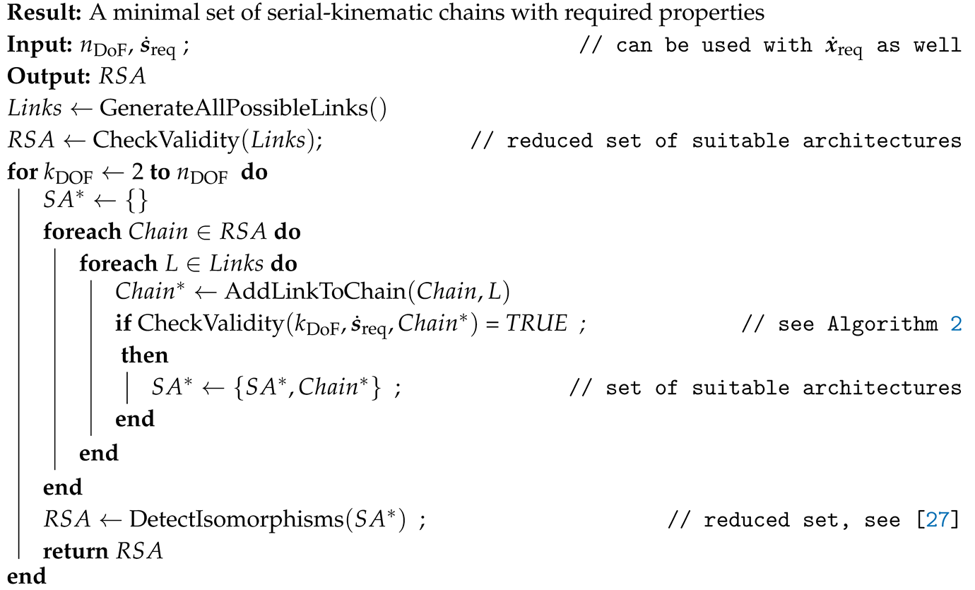 |
In [6], not only “simple limbs” (leg chains without kinematic loops) but also “complex” limbs containing parallelogram loops (there termed “Pa”) are considered. The expansion of an existing serial chain by an additional parallel branch is shown by [8, pp. 31,54] with the successive replacement of joints. By this, a spatial parallelogram with spherical joints can replace two successive universal joints.
2.3. Structural Synthesis of Parallel Robots
As summarized in [17], several methods are available for the synthesis of parallel robots, e.g., based on graph theory, group theory, or screw theory. According to [28, p. 325 f.], the structural synthesis of parallel robots can be sorted into three classes:
- methods based on the Chebychev-Grübler-Kutzbach criterion,
- the constraint screw-based method, and
- the motion-based method, also termed group-based.
Gogu proposes in [6] to distinguish his method of the theory of linear transformation and Di Gregorio’s method of velocity-loop equations as one distinct class of parallel-robot synthesis methods instead of counting them as part of the third class of [28]. In [12], the constraint-based and kinematic-based methods form two classes; the latter contains the group-theory approaches and the single-opened chain theory, which uses the POC (position and orientation criterion) matrix. The review article [29] names motion-based methods “based on the theory of differential geometry” and includes screw-based, Gogu’s, and POC methods. A detailed overview of the different publications and algorithms in these classes is omitted, and the reader is referred to the literature overview in comprehensive textbooks on parallel-robot synthesis like [5,6,28]. Instead, next to a general overview, a single representing algorithm from each class is presented in detail, showing the methods’ main characteristics and eventual drawbacks. This motivates the proposed algorithm in Section 3 to connect the structural synthesis and the dimensional synthesis.
Class 1: Chebychev-Grübler-Kutzbach (CGK) Criterion
The CGK criterion for robot synthesis is discussed in detail in [6] with various extensions. The criterion provides the total number of joint DoFs for a parallel mechanism with platform DoFs and m leg chains with joint DoFs, respectively. Under the assumption of only single-DoF joints, i.e., splitting up a spherical joint into three revolute joints, and using “basic mechanical schemes” [30] (, no branches), the equation in its basic form (taken from [30]) is
The resulting possible numbers of joint DoFs are listed in Figure 2(a–b) as a reprint from [8]. Tsai [31], e.g., obtained the same results with given examples for three- and six-DoF parallel robots. For instance, the Delta robot has 3T platform mobility, i.e., , and the leg chains each have joint DoFs, assigning a value of 15 on both sides of (6). For the case of 3T1R () or 3T2R (), the equation does not produce possible fully parallel () mechanical schemes with symmetric legs (), which are sketched in Figure 2(c). However, it can be shown by other methods for parallel-robot synthesis, presented in the following, that mechanisms for these cases exist that are termed overconstrained mechanisms [6, p. 120]. In summary, the main disadvantage of the criterion is that no statement on the type and alignment of joints and geometrical conditions can be obtained and that results are incomplete [28].
Class 2: Constraint Synthesis by the Virtual-Chain Approach and Screw Theory
A more systematic approach to the synthesis of parallel robots presents screw theory, which was introduced into mechanism analysis by Hunt [18]. Basics of screw theory in robotics can be obtained from [5,28,32,33]. The synthesis is targeted at robots with reduced mobility since the case of full mobility (3T3R) can be solved by any non-singular six-DoF leg chain in arbitrary alignment, given proper actuation. This synthesis can already be accomplished by the straightforward CGK criterion (Figure 2(b) with ).
Structural synthesis of parallel robots using screw theory is performed in [28] using the constraint-synthesis method. Screw theory was similarly used by [34] for the synthesis of overconstrained parallel robots with identical legs. To summarize [5], the platform motion of a parallel robot is defined as a twist system, where the allowed end-effector motion is described by its velocity components, e.g., , , and for a 2T1R motion (in the x-y-plane). This corresponds to screw vectors and with infinite pitch (corresponding to translational motion) and with zero pitch (corresponding to rotational motion) in the notation of [5]. The wrench system (of constraint force and moment) is reciprocal to the twist system of motion screws. In the 2T1R example, the parallel robot absorbs forces and moments and into the structure, resulting in corresponding reaction forces and moments. Therefore, the wrench system has two screws with pitch infinity (related to moments) and one screw with zero pitch (corresponding to a force).
The properties of twist and wrench systems for parallel kinematic chains can be simplified as follows. The twist system of the parallel kinematic chains is the intersection (in the mathematical sense, operator ∩) of the twist systems of the leg chains. This means that if a leg chain lacks one velocity component, no motion of the assembled parallel robot in that direction is possible. Reciprocally, the wrench system of the parallel kinematic chains is the union (operator ∪) of the wrench systems of the leg chains. Leg chains constraining an already constrained motion direction do not change the union of the legs’ wrench systems regarding that motion direction. Vice-versa, for serially connected joints, the resulting distal link’s twist system is the union of the joints’ twists, and the wrench system is the intersection of the single wrenches. In other words, additional joints in the leg chain provide further motion DoFs of the distal link, provided they are not linearly dependent (e.g., parallel) to previous joints. Leg chains of a parallel robot are selected such that the union of their wrench systems corresponds to the desired wrench system of the parallel robot. In the 2T1R example, this is the case if all leg chains have the reaction force and moments and , i.e., if the leg chains are also 2T1R. This planar-case example presents a parallel robot with full mobility.
In [5], an additional virtual chain is used for the synthesis. The method begins by defining an equivalent virtual chain for the robot platform’s given DoFs. For instance, a 3T motion (with only translation) is termed “PPP=” and uses the corresponding PPP chain, 3T1R (Schoenflies motion) is termed “PPPR=” and 3T2R is “PPPU=.” Possible leg chains and the virtual chain form a closed loop that must have the same DoFs as the parallel robot. Necessary geometric conditions of the desired DoFs are applied systematically for different screw systems leading to a list of compositional units that consist of several single-DoF joints in defined geometric conditions. The leg chain is then obtained by removing the virtual chain again. Subsequently, the single leg chains are assembled as parallel kinematic chains where each leg chain and the virtual chain hold twist- and wrench-system conditions. In the final step, the actuated joints have to be selected according to plausibility rules, giving the parallel mechanism (or parallel robot). The validity of the actuation is checked by the linear dependency of the wrench systems, which is performed mathematically by a determinant of a matrix with a maximal dimension of being non-zero.
The method provides more generality than the CGK criterion at the price of higher mathematical complexity and computational cost. Although the list of compositional units and leg chains in [5] is extensive, the algorithm has no means of assuring the completeness of all possible variations of leg chains and their alignments. The alignment of the base- and platform-coupling joints is not regarded explicitly in the synthesis process, even though they influence the robot’s mobility or the principal ability to close the kinematic constraints. Therefore, the dimensional parameters of the parallel robot that are subject to optimization in the envisioned dimensional synthesis of [10] would have to be obtained in another step.
Class 3: Motion-Based Synthesis at the Example of the Theory of Linear Transformations
In contrast to the constraint-synthesis method based on the wrench system of parallel kinematic chains, the synthesis can be performed motion-based, i.e., regarding the twist of leg chains and moving platform. This synthesis class is termed group-based since the displacement groups are used for motion representation [28]. A comprehensive work on a synthesis method within this class, based on the theory of linear transformation, is given by [6], together with an encyclopedic overview of leg chains for parallel robots with different platform motion patterns.
The desired motion of the parallel robot’s moving platform is characterized by the number a of independent translations and b of independent rotations, termed aTbR-type. First, a set of general conditions within the theory of linear transformations is generated, giving bounds for the mobility of the legs and the connectivity between platform and legs for defined cases of overconstraint and redundancy. By using evolutionary morphology [26], the leg chains are generated by permutation of design parameters (see Section 2.2). The name-giving linear transformations are the linear Jacobian mapping between (active-)joint velocity space and operational velocity vector space. The operational (platform) velocity vector space results from the intersection of the leg chains’ distal-link velocity vector spaces, which puts the twist-wrench relations introduced above in a different theoretical framework. Therefore, the assembled mechanism’s mobility assessment is effectively based on the Jacobian and other concepts of linear algebra applied to the underlying vector spaces and matrices.
In contrast to [5], the selection of active joints is not addressed explicitly, and the focus is on generating a complete set of possible leg chains, which are listed and depicted extensively. The alignment of coupling joints is not addressed in the synthesis part of [6] but is rather either regarded as given or as part of the leg-chain properties, as discussed in some of the examples, e.g., for the Delta robot in [6, p. 183 ff]. In Gogu’s following works, the leg chains are assembled to parallel robots with 3T [35], 3T1R [36], or 2T0R/2T1R [37]. However, the numerous figures in these books in the style of Figure 3(d) present kinematic sketches without a visible origin from a dimensional synthesis, which is recognizable by the mostly uniform length of links and impractical positioning of base joints that seem to be chosen matching to the chain’s neutral pose.
2.4. Design Rules for Parallel Robots
The synthesis methods above are dedicated to finding a kinematic structure (mechanical concept) for a parallel robot. For a technical realization within a mechanical structure, some design rules should be obeyed to obtain a robot that can be constructed easily (and cost-efficient) and has good performance characteristics, e.g., regarding stiffness and dynamics. Some of these principles are already included in the results of the structural synthesis. The design rules are summarized from the literature on robot synthesis like [8, p. 32 f.], [2, p. 21 ff.], [38, p. 43 ff.], and [12, p. 36 ff.]:
- Actuation should be proximal to the base, preferably in the first joint, to reduce moving mass and thereby increase dynamics (i.e., acceleration capabilities).
- Only one-DoF joints should be actuated.
- Leg chains should be identical (i.e., symmetric) to reduce cost and complexity.
- Passive prismatic joints should be omitted to avoid clamping.
- Joints should have three or fewer degrees of freedom.
- The number of joints should be kept low, ideally three per leg chain, to increase stiffness, reduce bending load, and decrease the number of geometric parameters.
- Two consecutive revolute joints should be realized as universal or spherical joints to avoid singularities and to improve manufacturability.
- Regular polygons should be avoided for the shape of the base and platform, as this may lead to geometric singularities.
- If spherical joints are used, they should be the platform-coupling joint [8, p. 46].
- Lift cylinders with additional levers have disadvantages regarding internal bending stress and should be omitted for this reason, as no reports of their use have been found by the author in the literature.
2.5. Literature Examples of Parallel Robots
Some illustrative examples of the results obtained by the synthesis methods presented above are shown in the following, separated according to the moving platform’s motion pattern (3T, 3T1R, 3T2R, and 3T3R). Other motion patterns like 2T3R are also possible but are omitted to focus on the most industrially relevant ones. Each comprehensive work on robot synthesis [5,28,35,36] lists numbers of possible leg chains and parallel robots, which will be briefly summarized and commented on. Only symmetric structures without closed kinematic loops (i.e., parallelograms) will be regarded in detail to maintain focus on the application within the combined robot synthesis. Not all the design principles from Section 2.4 are obeyed within the synthesis results, as the purpose of the lists is mostly to present possible kinematic structures, which need to be further developed for a specific task. The notation of [5] is used for distinguishing kinematic structures, where two R̀ denote two parallel revolute joints and Ŕ denotes a joint with a different axis. In addition to [5], prismatic joints with an axis parallel to a revolute R̀ joint are denoted by P̀.
2.5.1. Spatial Translational Motion: 3T DoFs (Translational Parallel Manipulators)
Examples of the parallel-robot structural synthesis results with only translational motion are depicted in Figure 3. Representative numbers of leg chains, parallel assemblies (without regarding actuation), and parallel mechanisms (i.e., parallel robots, regarding actuation) are given in Table 2.
Due to varying definitions in the references, the numbers only give a sense of dimension. Cylindrical and universal joints are included in [28] but would need to be derived from the chains with solely revolute or prismatic joints given in [5]. The latter also gives chains with multiple prismatic joints (such as PPP as a three-DoF chain), which contradicts the design rules of Section 2.4. Only basic structures are counted from [35] (without idle mobility but including prism and parallelogram limbs and passive prismatic joints).
Most parallel robots with 3T DoFs have leg chains with five joints, as in Figure 3(a,b,d). Using four-DoF chains like in Figure 3(c) provides only a small number of special isotropic cases (with constant Jacobian throughout the workspace) [5, p. 103]. In industrial pick-and-place applications, the Delta robot is the most prominent example of this type of parallel robot [1, p. 31], either as a 3-RUU with rotational actuation or a 3-PUU with linear actuation.
2.5.2. Schoenflies Motion: 3T1R DoFs
The 3T1R (Schoenflies) motion is obtained by adding another rotational DoF to the moving platform. Symmetric parallel robots with this motion pattern consist of leg chains with five joint DoFs. The overall number of results from the literature is summarized in Table 3. A direct comparison is impossible, as, e.g., [5] only lists mechanisms with actuated base joints, and [36] includes parallelograms and passive prismatic joints. The ten four-DoF chains of [28] are not feasible for symmetric actuation.
To the author’s best knowledge, no symmetric parallel robot with 3T1R motion is commercially used. Instead, the transmission of the rotational motion to the moving platform of a 3T mechanism is technically realized by either an additional serial joint on the platform, a passively extensible Cardan shaft, or an articulated traveling plate over the fourth leg chain [39,40]. Therefore, these structures can be classified as a parallel hybrid instead [7].
2.5.3. Spatial Translation with Pointing Motion: 3T2R DoFs
If two rotations of the moving platform are required, the restrictions within the synthesis are stricter than in the previous cases due to the overconstraint discussed in [20]. For this reason, symmetric 3T2R parallel robots with identical limbs were shown to exist rather late [34,41] and can not be obtained by the CGK criterion. Since then, published works on the analysis, modeling, and synthesis of these types of manipulators have increased, cf. [42,43].
Unlike other motion patterns, where simple leg chains such as UPU or RUU are feasible, leg chains for 3T2R robots contain at least four joints. For instance, [44] showed via screw theory that the 5-UPU chain (three joints) only has local mobility since the leg chains’ twist systems have no intersection, and the resulting twist system of the platform is empty. Some numbers are given in Table 4, with the same limitations as before. The overall number of results is much lower than for the 3T and 3T1R cases. Kinematic variants can be obtained by combining the R̀Ŕ joints into a U joint or vice versa. The resulting 5-PRUR is analyzed in [45], and the 5-RRUR and 5-R̀PR̀ŔŔ are shown in [46], which already comprises all symmetric 3T2R structures in the literature that the author found.
Other works cover asymmetric 3T2R parallel robots, as they have a higher relevance due to the lack of symmetric structures. Gogu’s approach is used by [42] to synthesize 3T2R robots with prismatic joints at the base with symmetric leg chains but asymmetric alignment. In [13], screw theory is used for synthesis together with a systematic deduction and naming scheme to build up a database of symmetric and asymmetric five-DoF parallel mechanisms.
2.5.4. Full Spatial Mobility: 3T3R DoFs
For the spatial full-mobility case, all leg chains must have six joint DoFs. Mechanical concepts are usually obtained with three joints to get a high-stiffness manipulator and simplify the construction. The most common mechanical structures are summarized in [30]. However, the leg chains may be realized with more joints if the joint DoFs sum up to six.
2.6. Summary of the State of the Art of Synthesis Methods
The presented methods from classes 2 and 3 from Section 2.3 are each able to produce a variety of parallel-robot structures, which is illustrated in some examples for different spatial motion patterns in Section 2.5. The existing encyclopedic listing of all possible structures can be used as a basis for the design of a new robot for a task. However, the vast number of solutions would still render a manual design process tedious, where a decision based on ranking the structures and their specific performance in the designated task would be beneficial [9, p. 175 ff]. As stated by [1, p. 25], the performance of and, therefore, the decision for a parallel robot structure strongly depends on the dimensioning.
The structural-synthesis methods above are not directly applicable in such a combined structural and dimensional synthesis [10]. Separating discrete and continuous design parameters is desirable for solving the optimization problem. The leg chains’ dimensional parameters are continuous and have to be separated in a subsequent step. The alignment of base and coupling joints belongs to the set of discrete parameters, as seen by the repeating type of alignments in the given examples. Due to the sole focus on the structural synthesis in the presented works, closing the kinematic loops is only regarded for selected examples. Doing this for all cases would require a dimensional synthesis.
Since the presented approaches from the literature do not rely on a dimensional synthesis, the mobility has to be investigated by symbolic computation of a matrix determinant [5] or rank [6]. A numeric evaluation would require suitable kinematic parameters and solving the inverse-kinematics problem.
The level of abstraction of screw theory [5] or displacement groups [6] is higher than undergraduate-level robotics fundamentals like Euclidean geometry, coordinate transformations, Euler angles, vector equations for kinematic constraints, and Jacobians. This level is sufficient for the model summarized in Section 2.1 and for textbooks like [1,21].
Furthermore, the discussed works are self-contained regarding their developed theory. Incomplete or even wrong assumptions leading to missing or non-mobile kinematic structures would not be detected since the examples are not all followed through to an assembled, simulated parallel robot but end in an enumeration of possible leg chains and kinematic sketches for the robots. This thought motivates the adaption of the presented methods into the structural-synthesis method proposed in the next section.
3. Parallel-Robot Structural Synthesis via Geometric Permutation
The structural synthesis given in the following is designed to provide results that can be used directly with the dimensional synthesis. Therefore, the robot has to be defined entirely in its structure after the synthesis. The principal procedure is similar to the one from [5] or [6], with a stronger focus on the discrete design parameters of the robot. All geometric parameters influencing the robot’s structural properties (such as mobility) are permuted with all possible combinations. Dimensional parameters are not explicitly considered if they do not change the structural properties.
Therefore, the method is termed “geometric permutation.” Geometric structural entities for permutation are the selection of the leg chain (Section 3.1) and the alignment of the base- and platform-coupling joints (Section 3.2 and Section 3.3), shown in Figure 4 for clarification.
An Overview of the structural-synthesis approach is presented in Figure 5 with references to the following subsections. Evaluation of the moving platform’s mobility (Section 3.5) is performed numerically with the dimensional synthesis algorithm of [10] and the rank of the robot’s Jacobian. The algorithm’s scope is on symmetric, fully parallel structures. An extension to non-identical leg chains or non-symmetric alignment of coupling joints is possible in principle. Still, these are technically more complex and have less chance of realization (see design rule 3 in Section 2.4). Leg chains must be generated before the parallel-robot synthesis, as discussed next.
3.1. Serial-Kinematic Leg Chains
As introduced in Section 2.2, the structural synthesis of serial leg chains for parallel robots can be obtained from established literature. This work uses the rule-based synthesis approach of [27] via permutation of (standard) DH parameters due to its direct applicability in dimensional synthesis and mathematical simplicity. The conditions from [27] for checking the validity of a kinematic structure (Algorithm 1, line 1) are modified for the leg-chain synthesis. Different motion patterns are required compared to the synthesis of serial-link robots, summarized in Table 5 in contrast to Table 1. For 3T parallel robots, the leg-chain synthesis is independent of the leg chain’s base-coupling joint alignment as constrained rotational motion due to the parallel assembly is verified subsequently. Therefore, no specific requirements regarding the rotational motion of leg chains are defined. The corresponding DoFs in or, equivalently, are marked by an asterisk (*), making the approach different from the one in [6] or [5]. For 3T1R parallel robots, a rotation of the leg-chain endpoint must permit the platform rotation. Different alignments of the first joints (in , , and direction) are, therefore, included in the chain’s synthesis, as shown by [27], to take into account the parallel robot’s base-joint coupling. For parallel robots with 3T2R motion and five-DoF leg chains, the tilting motion ( and ) has to be defined. The required motion vector is expressed by Cardan angles instead of a twist vector defined in the robot base frame since this allows mathematical isolation of the rotation in the pointing direction from the tilting motion.
| Algorithm 2: Checking the validity of a serial kinematic chain with requirement on angular velocities corresponding to intrinsically rotated axes |
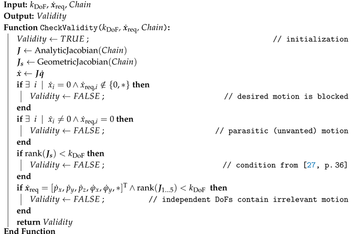 |
The validity of a serial chain is first checked by the desired motion pattern (Algorithm 2, lines 2 and 2) and the rank of the geometric Jacobian (line 2). The check is omitted for motion directions marked by *. For the synthesis of kinematic chains with a 3T2R motion pattern, the analytic Jacobian is used for the endpoint velocity of the chain and not the geometric Jacobian . The rank condition is then only applied to the first five rows of the analytic Jacobian (line 2). The rotational part of the analytic Jacobian is obtained by the approach that uses the product rule of differentiation from [19] to reduce the computational load of the computer algebra system. The results of the robot synthesis are stored in a database summarized in Section 4.1.
3.2. Alignment of the Base-Coupling Joint
The actual parallel-robot synthesis starts with a permutation of all possible alignments of the base-coupling joints, summarized in Table 6. Their positions are set symmetrically on a circle circumference in the base x-y-plane with radius . The direction of the coupling joint’s axis of rotation or translation is then selected according to geometric principles, which are also commonly found in existing robot structures in the literature (see Section 2.5). The main principles are shown in Figure 6 as vertical (v), tangential (t), radial (r), or conical (c) w.r.t. the base plane.
Six-DoF robots are usually built with a pairwise alignment of the base-coupling joint, as shown in Figure 7. In this case, the coupling-joint pair centers are aligned on a regular triangle, and the joint pairs are set around the angle bisector with a given distance . Likewise, a circle with a radius can be used for the joint center definition [48], cf. Figure 7(c). Alternatively, a geometric description with two parameters by the joint positions’ radius and an angle offset is possible, cf. [49] and [50, p. 70]. A distinction of a pairwise alignment to the previous modes is noted by capital letters, i.e., V for vertical, R for radial, T for tangential, and C for conical. The axes of the joint pairs are parallel (oriented at the regular triangle). Therefore, the conical alignment “C” geometrically corresponds to a pyramid. The case of two (spherical) joints at the same point can be achieved by choosing the pair distance accordingly.
For symmetric 3T2R parallel robots, the overconstraint requires a parallel alignment of all joint groups of the robot. The suitable base alignments are shown in Figure 8 as either parallel (p) in the base plane or vertical (v) to it, where the second joints of the chains have to be parallel.
The geometric condition is realized within the kinematic model of [19] by the orientation of the corresponding leg-chain base frame , depicted in the figures. The z-axis of this frame (blue arrows) corresponds to the first joint axis since the modified Denavit-Hartenberg notation from [21] is used for the kinematics model of the leg chain with .
Other authors have also addressed the problem of coupling-joint alignment. In [12, p. 38 ff.], the “frame configurations” (for 3T parallel robots) triangular (equivalent to t from Table 6), parallel (equivalent to v), and star-shaped (r or c) correspond to the symmetric configurations from above. Non-symmetric configurations not pursued in this paper are orthogonal (w.r.t. the other joints), U- or T-shaped. Apart from T and U, these alignments can also already be found in [9, p. 189]. In contrast to a selection of the alignment as a design parameter, [47] consider changing the alignment as a “static reconfiguration” of an existing alignment within the (re-)design process.
3.3. Alignment of the Platform-Coupling Joint
The next step of the structural synthesis is the permutation of the platform-coupling-joint alignment. The symmetric geometric primitives in the literature are similar to those for the base. Again, the main arrangements are vertical (v), tangential (t), and radial (r) relative to a circle in the x-y-plane of the robot’s platform frame with radius , as shown in Figure 9 and summarized in Table 7.
Pairwise alignments are marked by corresponding capital letters. The shifted pairwise alignment can be achieved by the pair distance parameter . This is common for hexapods, where base-joint pairs 1-2, 3-4, and 5-6 are connected to platform joints 6-1, 2-3, and 4-5 (both counted counterclockwise in top view, cf. [51].
In the case of leg chains with four joint DoFs for a spatial robot, the orientation of the coupling joint is already defined by the given base-joint alignment. Then, the orientation has to be chosen matching (“m”) to the base joint, which can be computed with the forward kinematics of the leg chain for any pose of the parallel robot, see Figure 10(a) or Figure 3(c). For 3T2R parallel robots, the joint direction is only chosen parallel in the plane, as depicted in Figure 10(b). The joint axis can be rotated in the platform plane by an angle . Other possible alignments are conical (c) in Figure 10(c) and tangential but inclined relative to the plane, shown in Figure 10(d). Both alignments can be configured with the inclination parameter , and the alignments correspond to the radial or tangential case for .
Within the model of Section 2.1, the joint alignment is set by the platform-coupling joint frames , to which the corresponding cut-joint frames have to be aligned.
3.4. Generation of Structures by Geometric Permutation
By permutation of leg chains (Section 3.1), base-joint coupling (Section 3.2), platform-joint coupling (Section 3.3), and actuated leg joint, the parallel robot structural synthesis is performed.
The number of possible leg chains is further increased by using variants for typical passive universal and spherical joints for parallel robots (see design rule 7 of Section 2.4). These variants are generated by replacing two subsequent orthogonal revolute joints with a universal joint (marked by distance between the joints) or by replacing three successive non-parallel revolute joints with a spherical joint, also by setting the according distances to zero. However, in opposition to design rule 6, the chains with only one-DoF joints are also maintained in the synthesis since performance criteria such as stiffness may not be relevant in all tasks. The disadvantage of multi-joint structures should be first checked within the dimensional synthesis and not already anticipated in the structural synthesis.
Further, variants for structural kinematic parameters are generated. In the reduction algorithm for isomorphism detection of [27] (Alg. 1, line 1), symbolic structural kinematic (DH) parameters (for prismatic joints) and (for all joints) remain for some joints, which mark the relative alignment of subsequent joint axes. These structural parameters are further varied by a combination of the cases parallel (), orthogonal (), and skew () for all of these parameters. If only specific alignments of these structural parameters lead to a valid parallel robot, this is stored as part of the synthesis results.
The permutation of the coupling-joint alignments leads to isomorphisms in the case of spherical joints since the alignment of the joint’s axis can not be specified, and, e.g., radial and vertical alignments describe the same architecture. These isomorphisms are removed from the synthesis results by only checking one alignment in this case. Some construction-oriented design rules from Section 2.4 are followed (e.g., no passive prismatic joints, rule 4), while others are ignored (like rule 8, regular polygon shape) to check their validity within the permutation-based approach. Since some structures provide no mobility with base-joint actuation, rule 1 (proximal actuation) is ignored in the structural synthesis and can be used as a filter in the dimensional synthesis.
3.5. Evaluation of the Platform Mobility
For each combination of coupling-joint alignment, leg chain, structural variants, and actuation, the mobility of the parallel robot’s moving platform has to be determined. A numeric implementation is used since symbolically evaluating the rank of the robot’s Jacobian in a computer algebra system may be too slow or too complex for some combinations. The approach is sketched in Figure 11 with a simplified flowchart of the dimensional-synthesis algorithm used for evaluation, which is described in more detail in [10].
After initialization of the robot model for the regarded structural combination, a single-objective particle-swarm optimization is configured to obtain numeric values for the dimensional parameters , i.e., the base and platform parameters from Table 6 and Table 7 and the leg chain’s DH parameters. After checks on the geometry’s validity, the inverse kinematics problem is solved for reference points and a reference trajectory , which presents a simple motion in the required motion pattern of the robot, e.g., the edges of a cube for a 3T robot. The testing trajectory for robots with spatial rotation (3T2R and 3T3R) contains small tilting angles since some structures have structural singularities in untilted configurations. If the IK fails, kinematic constraints are not met, or a parasitic motion occurs, the parameter evaluation returns with a corresponding violation penalty v for the fitness value f, and the next parameter value is tested. Otherwise, the mobility is investigated using the rank of the robot Jacobian, obtained numerically by the full kinematic constraints explained in Section 2.1. By this approach, the Jacobian is only evaluated numerically for parameters that produce a kinematically valid robot. Local pose-dependent singularities must be distinguished from structural loss of controllability in all poses. Therefore, the rank deficiency of the robot Jacobian is obtained as , where, e.g., for a 3T1R motion pattern and t is the time base of the testing trajectory. After assessing the rank deficiency for several numeric values of the parameters, a parameter-dependent singularity can be ruled out, the computation is finished, and the results are stored in a database, as discussed in Section 4.2.
The synthesis of symmetric 3T2R parallel robots presents a special case due to the overconstrained alignment of the leg chains. In the literature, only a few joint alignments are reported for this case, i.e., p-p (for revolute base joints, parallel in the base plane) and v-p (for vertical prismatic base joints). The notation v-p stands for base alignment “v” combined with platform alignment “p” (cf. Section 3.2 and Section 3.3). While the overall procedure is the same as for other motion patterns, checking the kinematic constraints requires special attention, as introduced in [20], which is omitted here for brevity.
4. Results of the Structural Synthesis
After checking the rank deficiency of the Jacobian for all structural combinations, a database of parallel robots is set up, as shown in Section 4.2, after a summary of the synthesis results of serial chains in Section 4.1. The procedure is elaborated in more detail in Section 4.3 in the example of planar motion with two translational and one rotational DoFs (2T1R). This is followed by a summary of the results for the different motion patterns in Section 4.4 (3T) to Section 4.7 (3T3R) and a remark on computation time in Section 4.8.
4.1. Database of Serial-Kinematic Chains
The serial-chain synthesis gives three chains with four joints, 52 with five, and 47 with six. The leg chains are published online in [52] and listed in the supplementary materials in Tables S1 to S3 with basic structural properties and their dimensional parameters within the optimization, using the DH notation. The chains are numbered and named uniquely for identification with a naming scheme like PR̀R̀ŔŔ (e.g., number 3 in five-DoF chain Table S2), where the same accents on letters R (revolute joint) and P (prismatic joint) mark parallelism of the joints’ axes. The resulting number of chains is lower than the number of serial-robot structures from [27, p. 40], where one three-DoF structure with 3T, 35 four-DoF structures with 3T1R (counting all base joint alignments), and 326 six-DoF with 3T3R motion pattern are reported. Similarly, [53] state 64 possible six-DoF robots and 59 with fewer DoFs, without further details. The reason for the lower number is the exclusion of chains with multiple prismatic joints and chains where the last joint (or second-last) is prismatic, which is infeasible for parallel robots. The numbers can not be directly compared to the lists of leg chains in [5] (15 four-joint chains and 75 five-joint chains for 3T, 118 five-joint chains for 3T1R, and 27 for 3T2R parallel robots) and [6, p. 445 ff.] (249 five-DoF chains), since the authors also include the chains excluded here, and the list in [6] contains parallelogram chains. The results of [28] only contain seven five-DoF chains for 3T robots (without universal or cylindrical joints) and 20 five-DoF chains for 3T1R robots (in an incomplete list), i.e., a lower number than found by the permutational synthesis. In summary, the set of results – regarding their prior restrictions – is quantitatively and qualitatively similar to the literature and sufficient for the combined synthesis pursued in this work.
4.2. Overview of the Parallel-Robot Database
The results of the parallel-robot synthesis of Section 3 are stored in a database containing the investigated combinations of serial chains, coupling-joint alignments, values for structural parameters (, ), and mobility of the moving platform. The database can then be accessed in the following dimensional synthesis [10] and is published online in [15]. A summary and an excerpt of the database, together with illustrative results, are given in the following Subsections 4.4–4.7, ordered by the moving platform’s motion pattern. Exemplary visualizations such as in Figure 13 are obtained with the Matlab implementation of the synthesis toolbox [14,54], where revolute joints are shown by cylinders, prismatic joints by cuboids, color red denotes active and blue passive joints, inspired, e.g., by the Matlab robotics toolbox from [55]. The full results are listed in the supplementary materials in Tables S4 to S7. The database is implemented in the form of tables with references to the defined set of base alignments (Table 6), platform alignments (Table 7), and leg chains (Tables S1 to S3). This presents a more modular concept than, e.g., the 3T2R and 2T3R parallel-robots database in [13], which codes all structural information into one character string.
As for the serial chains, each parallel robot has a unique number (“PR#”) and a name, as can be seen by the exemplary excerpt for the 3T robots in Table 10. The name follows the notation from the literature [1,5] with additional accents on prismatic joints to mark parallelism efficiently. The accents within the parallel-robot name can be different than in its constituting serial chain, referenced by the column “Leg#,” as the assembly can enforce certain leg joints to be parallel. The second number marks variants of the general leg chain within the first column; e.g., PR 1.2 denotes the second variant of the first general chain of a specific motion pattern. The corresponding series of joints, including universal and spherical, is named in the “Joints” column. Coupling-joint alignments with full rank in the robot Jacobian are given in the last column with a dash separating the base- and platform-coupling symbol, introduced in Section 3.2–Section 3.3. Expressions are written compactly, e.g., as (r,t)-v, including the modes r-v and t-v. Similarly, the term (v-t)-(r-t) includes v-r, v-t, t-r, and t-t. Alignments that provide a feasible solution to the inverse kinematics but have a rank deficiency (“R.D.”) in the Jacobian regarding the chosen actuation are written in red.
4.3. Minimal Example: Planar Parallel Robots (2T1R)
In the case of planar motion with two translational and one rotational DoFs, the leg chains need to have full mobility regarding the planar 2T1R motion. Therefore, the structural synthesis of serial chains from the state of the art in Section 2.2 is not affected by the changes for legs of parallel robots with reduced mobility presented in Section 3.1. Chains with three joints are required; see Figure 2(a). Algorithm 1 creates a permutation of prismatic and revolute joints: single R and P joints to start with, then chains of RR, RP, PR, and PP as result of the first iteration (), and chains of RRR, RRP, RPR, RPP, PRR, PRP, and PPR as result of the second iteration (). As the motion is restricted to a plane, only revolute joints orthogonal to the plane and prismatic joints in the plane result from the permutation of Denavit–Hartenberg parameters (in the modified notation from [21]). The chain with joints PPP is not valid for 2T1R since the rotational DoF is not articulated and the check in Algorithm 2, line 2, fails. Only the leg chains given in Table 8 fulfill the design rules of Section 2.4 and are used as leg chains for parallel-robot synthesis.
The permutation of coupling joints is not required for the revolute coupling joints as it is already known that only vertical alignments of these joints relative to the plane are valid. The numeric validation of Section 3.5 returns a full rank of the robots’ Jacobians, visible in Table 9 for the 3-RRR (parallel robot number 3) and 3-RPR (PR 2).
The procedure is displayed in the example of the 3-RRR in more detail. The dimensional synthesis obtains a feasible result with the following parameters that were subject to optimization: =1371.8 mm, =1053.3 mm, =697.1 mm, =405.2 mm, and a base rotation against the world frame of =−76.95°. The base position is set in the center of the task at =650 mm and =350 mm. The robot is depicted in the five reference points of the testing trajectory of the 2T1R motion in Figure 12.
The symbolic derivation of the inverse Jacobian from (5) for the 3-RRR using the two-step projection method implemented via Maple in the robot database [16] yields
which has full rank. The joint coordinate of the jth joint of the ith leg chain is denoted by . The rank of the matrix is only evaluated numerically within the synthesis, as described in Section 3.5. In the two poses of Figure 12(a–b), the matrix is
As these and other (inverse) Jacobian matrices have full rank, no singular poses arose within the synthesis, and the robot is stored in the database as without rank deficiency.
Actuation of the second joint of the 3-RRR is valid as well. The prismatic base-coupling joint of the 3-PRR (PR 1) may be placed radial (r), tangential (t), or parallel (p) in the plane, according to the description in Section 3.2. Other alignments would lead to a motion out of the plane, and trying this will lead to abortion of the evaluation due to parasitic motion, shown in the scheme of Figure 11. To summarize, three different parallel robots result in the synthesis for the 2T1R motion.
The overall principle remains the same for other DoFs described next, despite that more combinations for leg chains and coupling joints are considered.
4.4. Parallel Robots with Three Degrees of Freedom and 3T Motion
In total, 42 different parallel-kinematic assemblies were found for 3T motion, entirely listed in Table S4. By variation of joint implementation and actuation, 126 parallel-robot candidates can be distinguished, from which 106 were found to be valid, and 20 were found invalid, marked as rank-deficient. An excerpt of these results is given in Table 10.
The principal meaning of the Jacobian’s rank can be explained in the example of the 3-P̀R̀R̀R̀ (PR 1.1), shown in Figure 13, which is also discussed in detail in [5, p. 103 f.] (in a general form where the prismatic joints’ axis is not parallel to the revolute joints axes as here), see Figure 3(c). Only the conical base alignment of Figure 13(a) with matching (inclined, i) platform alignment provides a valid solution for this leg chain in a symmetric alignment. In the v-v alignment of Figure 13(b), the kinematic inversion (flipping proximal and distal end) of the SCARA kinematics is achieved. The linear actuation only performs motion in the vertical direction, and both other translational DoFs are passive, giving a rank deficiency of two. Similarly, the tangential alignment (t-t, Figure 13 c) cannot actuate the vertical motion, and the rank deficiency is one.
The results with few joints are especially interesting for a technical realization (design rule 6 of Section 2.4). The relevant existing structures can be reproduced, such as the Delta robot (3-RUU, PR 42.5, Figure 14 d), the linear Delta robot (3-PUU, PR 6.2, Figure 14 b) or the 3-UPU (PR 27.4, Figure 14 c). The 3-PRUR (PR 4.2) is shown exemplarily in Figure 14(a) out of the four-joint chains. The results of the permutational synthesis include the overall set of results of the literature summarized in Table 2 (Section 2.5.1) when applying filters from Section 3 regarding the leg chain and actuation (no passive or last prismatic joints, cylindrical joints, or parallelogram subchains). This holds for [28, p. 356] (six mechanisms with one P-joint and otherwise R-joints, one with only R-joints, and 19 with universal joints) and for [5, p. 96] (four four-joint structures with one P-joint, five five-joint structures with only R-joints, and 30 five-joint structures with one P-joint).
4.5. Parallel Robots with Four Degrees of Freedom and 3T1R Motion
For 3T1R motion, 39 assemblies were found, listed in Table S5. By variation, 120 parallel-robot candidates can be formed: 63 valid parallel robots and 57 rank-deficient mechanisms. An illustrative excerpt of these results is given in Table 11 and Figure 15.
The 4-R̀PR̀ŔŔ in a 4-RPUR variant (PR 15.3) can be found similarly with t-c alignment in [28, p. 356] performing a 1T3R motion. The t-v alignment shown in Figure 15(a) performs the 3T1R motion. The 4-UPU (PR 27.4) given in [28, p. 342] is rank-deficient by one if using an actuated P-joint. The structure 4-R̀R̀R̀ŔŔ (PR 35.1, Figure 15 c) is, e.g., shown in [5, Figure 9.10a] in the exact v-t alignment.
Regarding the chosen filters (and thereby reducing the numbers in Table 3), the total number of parallel robots exceeds the ones from the literature. Since [28, p. 342] do not give information on actuation and rank, the 39 results can only be compared to their 20 explicitly reported symmetric assemblies with five joints. Out of the five mechanisms with 4R-1P and six mechanisms with 5R chains with actuated first joint of [5, p. 151], six were reproduced with full rank (PR 4, 6, 35, 39, and 38). The other five are subject to a geometric condition for the parameters, which is out of the scope of this paper. The geometric condition requires two non-orthogonal and non-parallel angles to follow an exact relation, which is difficult to manufacture. The kinematics were validated by a manual implementation. For two robots (modifications of PR 2 and 5), the shown coupling-joint alignments did not lead to the full rank found by [5]: The correspondence of the generated PR to the numbers from [5, p. 157] in parentheses is: (1) PR 35.1 v-t, (2) PR 39.1 v-v, (3) PR 38.1 v-v, (4) PR 36.1 v-i (there with ), (5) PR 37.1 v-v (with and non-orthogonal and ), (6) PR 35.1 c-v (with ), (7) PR 3.1 v-t, (8) PR 6.1 v-v (with ), (9) PR 4.1 v-v, (10) PR 5.1 v-i (with ; rank loss), (11) PR 2.1 v-v (with and non-orthogonal ; rank loss).
Only twelve simple-limb PR from [36, p. 59] match the design rules of Section 2.4. Out of these, the full rank was reproduced for all: The correspondence of the generated PR to the numbers from [36, p. 59] in parentheses is: (1) PR 37.2, (2) PR 39.1, (3) PR 35.1, (4) coupling-joint isomorphism, (5) PR 36.3,
(7) PR 31.1, (8) PR 22.1, (9) PR 6.1, (10) PR 6.1 (with , i.e., 4-P̀R̀ŔŔR̀), (11) PR 27.1, (12) PR 4.1, (20)
PR 15.1, (30) PR 13.1 (assuming the C joint as R̀P̀). Since 19 of the 39 assemblies in Table S5 contain at least one full-rank parallel robot, six assemblies were not found by [36]: PR 3, 23, 24, 33, 34, and 38. Only PR 3 and 38 are listed in [5].
The numbers suggest that the permutational synthesis qualitatively replicated the results from the literature and found new symmetric parallel robots for 3T1R motion.
4.6. Parallel Robots with Five Degrees of Freedom and 3T2R Motion
For 3T2R motion, 19 assemblies and 46 parallel-robot candidates are listed in Table S6. Of them, 27 are valid, and 19 are invalid. An excerpt of these results is given in Table 12. A direct comparison of the results with the similar 3T2R robot database of [13] is impossible due to a different naming scheme, the inclusion of asymmetric robots, and the unavailability of detailed results. Other systematic overviews for comparison, as for 3T and 3T1R motion, do not exist, apart from the data in Table 4.
One interesting result of the permutational synthesis is that tangential and radial base-joint alignments are possible for the 5-PR̀R̀ŔŔ structure (PR 3.2), as shown in Figure 16 at the 5-PRUR variant. The t-p coupling of Figure 16(b) presents a valid parallel robot, while the r-p alignment of Figure 16(c) has a rank deficiency of one. In the literature, the 5-PRUR is shown in the v-p alignment of Figure 16(a) [46] or with asymmetric alignment [56]. The p-p alignment of Figure 16(d) presents a common solution for many 3T2R parallel robots.
Other known structures like the 5-RPUR (PR 8.3) [43,57,58] can be reproduced as well; see Figure 17(a). The 5-RUPR (PR 17.2) presents a kinematic inversion. For revolute actuation, e.g., the 5-RRUR reported in [46] can be reproduced (PR 18.5) together with other variants (see Figure 17 b–c) and kinematic inversions. Eliminating the kinematic inversions is not performed since, in some cases, only one variant is valid, as shown by the 5-RURR. It cannot be obtained with proximal actuation (PR 19.5) since the universal joint can not be actuated, and actuating the first joint leads to a rank deficiency, unlike the distal actuation 5-RURR (PR 19.6). To the author’s best knowledge, some of the generated structures have not been presented within the literature on 3T2R parallel robots, such as the 5-R̀R̀PŔŔ (PR 13.1) in Figure 17(d).
4.7. Parallel Robots with Six Degrees of Freedom (3T3R Motion)
Finally, for 3T3R motion, 47 assemblies and 234 parallel-robot candidates are listed in Table S7 in the supplementary materials, including 230 valid and 4 invalid. An excerpt of these results is given in Table 13. The relevant three-joint structures from [30] – 6-RUS (Hexa robot, PR 47.8), 6-UPS (hexapod robot, PR 26.3), and 6-PUS (e.g., Hexaglide, PR 6.3) – can be reproduced, as shown in Figure 18. Also, various combinations of four-joint chains with revolute and universal joints are obtained, as depicted in Figure 19 in three examples.
Since the synthesis of 3T3R parallel robots is trivial from the perspective of selection and alignment of leg chains, no results for comparison were found in the literature for cases with more than three joints. However, many authors have reported these cases to be technically irrelevant due to difficulties in manufacturing (e.g., higher number of parts) and control (e.g., due to the increasing possibility of working-mode changes). The parallel robots consisting of four-, five- and six-joint chains are maintained within the results list for completeness. These structures may provide advantages in the workspace size compared to structures with only three joints per chain. Still, they may only be of academic interest rather than provide practical benefit. This, however, has to be verified in a subsequent dimensional synthesis (cf. [10]). One finding from the permutational synthesis of 3T3R parallel robots is that the design rule 8 from Section 2.4 only holds for specific architectures such as the hexapod (PR 26.3). There, the combination of the circular base and platform alignments (v/t/r/c/p) is rank-deficient. At least one pairwise alignment (V/T/R/C) for the base or the platform has to be used. Other structures, such as 6-PUS (PR 6.3), may be realized without restrictions on the alignment.
4.8. Computation Time
Due to the geometric permutation elaborated in Section 3, the dimensional synthesis is performed for all combinations of base coupling, platform coupling, and leg chain. The latter already includes variants of leg chains by using universal or spherical joints. The number of checked permutations is given in Table 14 by for all motion patterns. Out of these, do not need to be checked by applying rules 2 and 4 of Section 2.4. The number is large since many leg chains in the database contain multiple prismatic joints. The remaining parallel-robot candidates were optimized within the dimensional synthesis. For instance, the data for 2T1R can be compared to Table 9, where corresponds to the six different alignments and corresponds to the leg chains RRP, RPP, and PRP.
For , a parameterization was found for closing the kinematic constraints and determining the Jacobian rank or a parasitic motion. This took around 4 min on average on an Intel Xeon computing cluster [59] with parallel computing. The other runs of the dimensional synthesis failed mainly due to the inability to close the kinematic constraints. Then, the iteration limit (200 generations, 200 particles) was met, and it took a longer time of 46 min. Due to multiple runs and some manual inspections, finding no solution can be attributed to the impossibility of the tested PR candidate.
In summary, about 14,600 h of CPU time were used to build up the database by numeric evaluation with dimensional synthesis. Additionally, around 20 min of CPU time is necessary for compiling the functions per leg chain, summing up to several hundred CPU hours for the whole database. The numbers should only be seen as an estimate of the overall order of magnitude since computation time is subject to parameters like the iteration limit, depends on the computing hardware, and does not include some general overhead of the Matlab toolbox. Since the database is available as open source [15], no repetition of this computational effort is necessary.
5. Discussion
As a result of this work, a permutation-based method for structural synthesis of parallel robots is proposed and validated against the literature regarding the resulting structures. The structures form a database of serial chains and parallel assemblies in a modular way. The comparison against existing works shows that results from other approaches of higher mathematical abstraction can be reproduced by using only numeric and no symbolic computation. Some missing mechanisms with 3T1R and 3T2R motion patterns were identified in the state of the art, thereby extending the list of known parallel robots. Due to the automatic derivation of the database by design-variable permutation and numeric evaluation, errors introduced by manual work can be ruled out.
With the explicit check of the matrix rank, constraints, and parasitic motion, false-positive results can be ruled, i.e., parallel robots that are marked as with full rank in the database but are actually rank-deficient or non-mobile. The case of false negatives (robots marked as rank-deficient that actually are not) is addressed by the tilted orientation in the reference trajectory, assessing the highest achievable rank, and finishing the dimensional synthesis only after multiple random parameter sets have succeeded with the full rank. However, the approach cannot guarantee avoiding false-negative results completely.
The approach can, in principle, be extended to parallel robots that are not symmetric or not fully parallel (with more than one actuator per leg chain) or to hybrid robots (parallel-serial, parallel-parallel, or parallel with quasi-serial leg chains). Including other motion patterns like 1T2R, 2R, or 3R is also possible by the proposed kinematic model. The characteristic geometric conditions of the leg chains for these DoFs, such as multiple joint axes that intersect in one point, would need special attention.
The dimensional-synthesis algorithm, which later relies on the structures, is also used for the numerical evaluation within the structural synthesis. The database can be used to find a parallel robot for a given task by performing a dimensional synthesis, giving the name combined structural and dimensional synthesis.
Funding
This research is based on works that received funding from the Deutsche Forschungsgemeinschaft (DFG) under grant number 341489206. Computation for the structural synthesis was performed on the computing cluster of LUH funded by DFG (project number INST 187/592-1 FUGG).
Data Availability Statement
The framework described in Section 3 is published open-source at https://github.com/SchapplM/robsynth-structdimsynth. The resulting robot database (Section 4 and Appendix) is published as raw data at https://github.com/SchapplM/robsynth-serroblib (serial leg chains) and https://github.com/SchapplM/robsynth-parroblib (parallel robots) and as document in the supplementary materials provided together with this paper.
Acknowledgments
The author thanks Tobias Ortmaier and Max Bartholdt for proof-reading an earlier version of the manuscript.
Conflicts of Interest
The author declares no conflicts of interest. The funders had no role in the design of the study, in the collection, analyses, or interpretation of data, in the writing of the manuscript, or in the decision to publish the results.
Abbreviations
The following abbreviations are used in this manuscript:
| 3T | three translations (in the sense of degrees of freedom; also termed 3T0R) |
| 3T1R | three translations and one rotation (also for 3T2R and 3T3R) |
| C | cylindrical joint |
| DH | Denavit–Hartenberg |
| DoFs | degrees of freedom |
| IK | inverse kinematics |
| P | prismatic joint |
| PR | parallel robot |
| R | revolute joint |
| S | spherical joint |
| U | universal joint |
References
- Merlet, J.P. Parallel Robots, 2nd ed.; Vol. 128, Solid Mechanics and Its Applications, Springer Science & Business Media, 2006. [CrossRef]
- Neugebauer, R., Ed. Parallelkinematische Maschinen: Entwurf, Konstruktion, Anwendung; VDI-Buch, Springer: Berlin and Heidelberg, 2006. [CrossRef]
- Russo, M.; Zhang, D.; Liu, X.J.; Xie, Z. A review of parallel kinematic machine tools: Design, modeling, and applications. International Journal of Machine Tools and Manufacture 2024, p. 104118. [CrossRef]
- Hunt, K.H. Structural kinematics of in-parallel-actuated robot-arms. Journal of Mechanisms, Transmissions, and Automation in Design 1983, 105, 705–712.
- Kong, X.; Gosselin, C.M. Type synthesis of parallel mechanisms; Springer Publishing Company, Incorporated, 2007. [CrossRef]
- Gogu, G. Structural Synthesis of Parallel Robots, Part 1: Methodology; Vol. 866, Springer, 2008. [CrossRef]
- Antonov, A. Parallel–Serial Robotic Manipulators: A Review of Architectures, Applications, and Methods of Design and Analysis. MDPI Machines 2024, 12. [CrossRef]
- Frindt, M. Modulbasierte Synthese von Parallelstrukturen für Maschinen in der Produktionstechnik (Module-based synthesis of parallel structures for machines in production technology). PhD thesis, Technische Universität Braunschweig, 2001. Parts are published in English in [30].
- Krefft, M. Aufgabenangepasste Optimierung von Parallelstrukturen für Maschinen in der Produktionstechnik (Task-specific optimization of parallel structures for machines in manufacturing technology). PhD thesis, Technische Universität Braunschweig, 2006.
- Schappler, M. Dimensional Synthesis of Parallel Robots Using Bilevel Optimization for Design Optimization and Resolution of Functional Redundancy. MDPI Robotics 2025, 14. [CrossRef]
- Kirchner, J. Mehrkriterielle Optimierung von Parallelkinematiken (Multi-Criterial Optimization of Parallel Kinematics). PhD thesis, Technische Universität Chemnitz, 2000.
- Prause, I. Task-Based Comparison of Parallel Translational Kinematic Structures. PhD thesis, RWTH Aachen, 2016. [CrossRef]
- Ding, H.; Cao, W.; Cai, C.; Kecskeméthy, A. Computer-aided structural synthesis of 5-DOF parallel mechanisms and the establishment of kinematic structure databases. Robotica 2015, 83, 14–30. [CrossRef]
- Schappler, M. Matlab Toolbox for Structural and Dimensional Robot Synthesis. https://github.com/SchapplM/robsynth-structdimsynth, accessed on 2025-03-06.
- Schappler, M. Parallel-Robot Database. https://github.com/SchapplM/robsynth-parroblib, accessed on 2025-03-06.
- Schappler, M.; Job, T.D.; Ortmaier, T. A Maple Toolchain for Rigid Body Dynamics of Serial, Hybrid and Parallel Robots. Maple in Mathematics Education and Research. Springer International Publishing, 2021. [CrossRef]
- Merlet, J.P.; Gosselin, C. Parallel Mechanisms and Robots. In Springer Handbook of Robotics; Siciliano, B.; Khatib, O., Eds.; Springer Berlin Heidelberg, 2008; pp. 269–285. [CrossRef]
- Hunt, K.H. Kinematic geometry of mechanisms; Vol. 7, Oxford University Press, USA, 1978.
- Schappler, M.; Tappe, S.; Ortmaier, T. Modeling Parallel Robot Kinematics for 3T2R and 3T3R Tasks Using Reciprocal Sets of Euler Angles. MDPI Robotics 2019, 8. [CrossRef]
- Schappler, M. Structural and Dimensional Synthesis of Overconstraint Symmetric 3T2R Parallel Robots using Tait-Bryan-Angle Kinematic Constraints. International Symposium on Advances in Robot Kinematics. Springer, 2022. [CrossRef]
- Briot, S.; Khalil, W. Dynamics of Parallel Robots; Vol. 35, Mechan. Machine Science, Springer, 2015. [CrossRef]
- Schappler, M. Inverse Kinematics for Task Redundancy of Symmetric 3T1R Parallel Manipulators using Tait-Bryan-Angle Kinematic Constraints. International Symposium on Advances in Robot Kinematics. Springer, 2022. The author’s version of the accepted manuscript is available at https://doi.org/10.15488/12464 free of charge., . [CrossRef]
- Schopen, M. Die Auswahl von Handhabungsgeräten aufgrund der charakteristischen Merkmale ihrer kinematischen Strukturen (The selection of handling devices based on the characteristics of their kinematic structures). PhD thesis, RWTH Aachen, 1987.
- Wang, K.; Lien, T.K. Structure design and kinematics of a robot manipulator. Robotica 1988, 6, 299–309. [CrossRef]
- Gogu, G. Families of 6R orthogonal robotic manipulators with only isolated and pseudo-isolated singularities. Mechanism and Machine Theory 2002, 37, 1347–1375. [CrossRef]
- Gogu, G. Evolutionary Morphology. Advances in Integrated Design and Manufacturing in Mechanical Engineering; Bramley, A.; Brissaud, D.; Coutellier, D.; McMahon, C., Eds.; Springer Netherlands: Dordrecht, 2005; pp. 389–402.
- Ramirez, D.A. Automatic Generation of Task-specific Serial Mechanisms using Combined Structural and Dimensional Synthesis. PhD thesis, Gottfried Wilhelm Leibniz Universität Hannover, 2018. [CrossRef]
- Huang, Z.; Li, Q.; Ding, H. Theory of parallel mechanisms; Vol. 6, Springer Science & Business Media, 2012. [CrossRef]
- Meng, X.; Gao, F.; Wu, S.; Ge, Q.J. Type synthesis of parallel robotic mechanisms: Framework and brief review. Mechanism and machine theory 2014, 78, 177–186. [CrossRef]
- Frindt, M.; Krefft, M.; Hesselbach, J. Structure and type synthesis of parallel manipulators. In Robotic Systems for Handling and Assembly; Springer, 2010; pp. 17–37. [CrossRef]
- Tsai, L.W. Systematic enumeration of parallel manipulators. In Parallel kinematic machines; Boër, C.R.; Molinari-Tosatti, L.; Smith, K.S., Eds.; Springer London, 1999; pp. 33–49. [CrossRef]
- Murray, R.M.; Li, Z.; Sastry, S.S.; Sastry, S.S. A mathematical introduction to robotic manipulation; CRC press, 1994.
- Lynch, K.M.; Park, F.C. Modern Robotics: Mechanics, Planning, and Control; Cambridge University Press, 2017.
- Fang, Y.; Tsai, L.W. Structure synthesis of a class of 4-DoF and 5-DoF parallel manipulators with identical limb structures. The international journal of Robotics Research, 21, 799–810.
- Gogu, G. Structural Synthesis of Parallel Robots, Part 2: Translational Topologies with Two and Three Degrees of Freedom; Springer, Berlin, 2009.
- Gogu, G. Structural Synthesis of Parallel Robots, Part 5: Basic Overconstrained Topologies with Schönflies Motions; Springer, Berlin, 2014.
- Gogu, G. Structural Synthesis of Parallel Robots, Part 3: Topologies with Planar Motion of the Moving Platform; Springer, Berlin, 2010.
- Zhang, D. Parallel robotic machine tools; Springer Science & Business Media, 2009. [CrossRef]
- Pierrot, F.; Nabat, V.; Company, O.; Krut, S.; Poignet, P. Optimal Design of a 4-DOF Parallel Manipulator: From Academia to Industry. IEEE Transactions on Robotics, 25, 213–224. [CrossRef]
- Lian, B.; Wang, X.V.; Wang, L. Static and dynamic optimization of a pose adjusting mechanism considering parameter changes during construction. Robotics and Computer-Integrated Manufacturing 2019, 59, 267–277. [CrossRef]
- Huang, Z.; Li, Q. Type synthesis of symmetrical lower-mobility parallel mechanisms using the constraint-synthesis method. The International Journal of Robotics Research, 22, 59–79.
- Motevalli, B.; Zohoor, H.; Sohrabpour, S. Structural synthesis of 5 DoFs 3T2R parallel manipulators with prismatic actuators on the base. Robotics and Autonomous Systems, 58, 307–321. Towards Autonomous Robotic Systems 2009: Intelligent, Autonomous Robotics in the UK, . [CrossRef]
- Gallardo-Alvarado, J.; Abedinnasab, M.H.; Islam, M.N. A Simple Method to Solve the Instantaneous Kinematics of the 5-RPUR Parallel Manipulator. Robotica, 37, 1143–1157. [CrossRef]
- Huang, Z.; Li, Q.C. General Methodology for Type Synthesis of Symmetrical Lower-Mobility Parallel Manipulators and Several Novel Manipulators. The International Journal of Robotics Research 2002, 21, 131–145. [CrossRef]
- Tale-Masouleh, M.; Saadatzi, M.H.; Gosselin, C.; Taghirad, H.D. A geometric constructive approach for the workspace analysis of symmetrical 5-PRUR parallel mechanisms (3T2R). ASME International Design Engineering Technical Conferences and Computers and Information in Engineering Conference; , 2010; pp. 1335–1344. [CrossRef]
- Cao, W.a.; Ding, H.; Yang, D. A Method for Compliance Modeling of Five Degree-of-Freedom Overconstrained Parallel Robotic Mechanisms With 3T2R Output Motion. Journal of Mechanisms and Robotics, 9. [CrossRef]
- Stechert, C.; Franke, H.J. Requirement-oriented Configuration of Parallel Robotic Systems. The Future of Product Development; Krause, F.L., Ed. Springer Berlin Heidelberg, 2007, pp. 259–268. [CrossRef]
- Schütz, D.; Budde, C.; Raatz, A.; Hesselbach, J. Parallel Kinematic Structures of the SFB 562. Robotic Systems for Handling and Assembly; Schütz, D.; Wahl, F.M., Eds. Springer Berlin Heidelberg, 2011, pp. 109–124. [CrossRef]
- Su, Y.; Duan, B.; Zheng, C. Genetic design of kinematically optimal fine tuning Stewart platform for large spherical radio telescope. Mechatronics, 11, 821–835. [CrossRef]
- von Daake, A. Beitrag zur Kalibrierung und anforderungsbasierten Arbeitsraumoptimierung parallelkinematischer Manipulatoren in Hexapodbauweise. PhD thesis, Technische Universität Clausthal, 2012.
- Fiore, E.; Giberti, H. Optimization and comparison between two 6-DoF parallel kinematic machines for HIL simulations in wind tunnel. MATEC web of conferences. EDP Sciences, 2016, Vol. 45, p. 04012. [CrossRef]
- Schappler, M. Serial-Robot Database. https://github.com/SchapplM/robsynth-serroblib, accessed on 2025-03-06.
- Baumgärtner, J.; Kanagalingam, G.; Fleischer, A.P.J. One Problem, One Solution: Unifying Robot and Environment Design Optimization. arXiv preprint arXiv:2310.05520 2023. [CrossRef]
- Schappler, M. Matlab Robotics Toolbox. https://github.com/SchapplM/robotics-toolbox, accessed on 2025-03-06.
- Corke, P. Robotics, Vision and Control. Springer Tracts in Advanced Robotics 2011. [CrossRef]
- Masouleh, M.T.; Saadatzi, M.H.; Gosselin, C.; Taghirad, H.D. A geometric constructive approach for the workspace analysis of symmetrical 5-PRUR parallel mechanisms (3T2R). ASME 2010 International Design Engineering Technical Conferences and Computers and Information in Engineering Conference. American Society of Mechanical Engineers, 2010, pp. 1335–1344. [CrossRef]
- Masouleh, M.T.; Gosselin, C.; Husty, M.; Walter, D.R. Forward kinematic problem of 5-RPUR parallel mechanisms (3T2R) with identical limb structures. Mechanism and Machine Theory, 46, 945–959. [CrossRef]
- Amine, S.; Masouleh, M.T.; Caro, S.; Wenger, P.; Gosselin, C. Singularity analysis of 3T2R parallel mechanisms using Grassmann–Cayley algebra and Grassmann geometry. Mechanism and Machine Theory, 52, 326–340. [CrossRef]
- LUIS (Leibniz Universität IT Services). Hardware specifications of cluster compute nodes. https://docs.cluster.uni-hannover.de/doku.php?id=resources:computing_hardware, accessed on 2024-10-31.
Figure 1.
Sketch of the general parallel-robot kinematics, modified from [10] (under CC-BY License)
Figure 1.
Sketch of the general parallel-robot kinematics, modified from [10] (under CC-BY License)
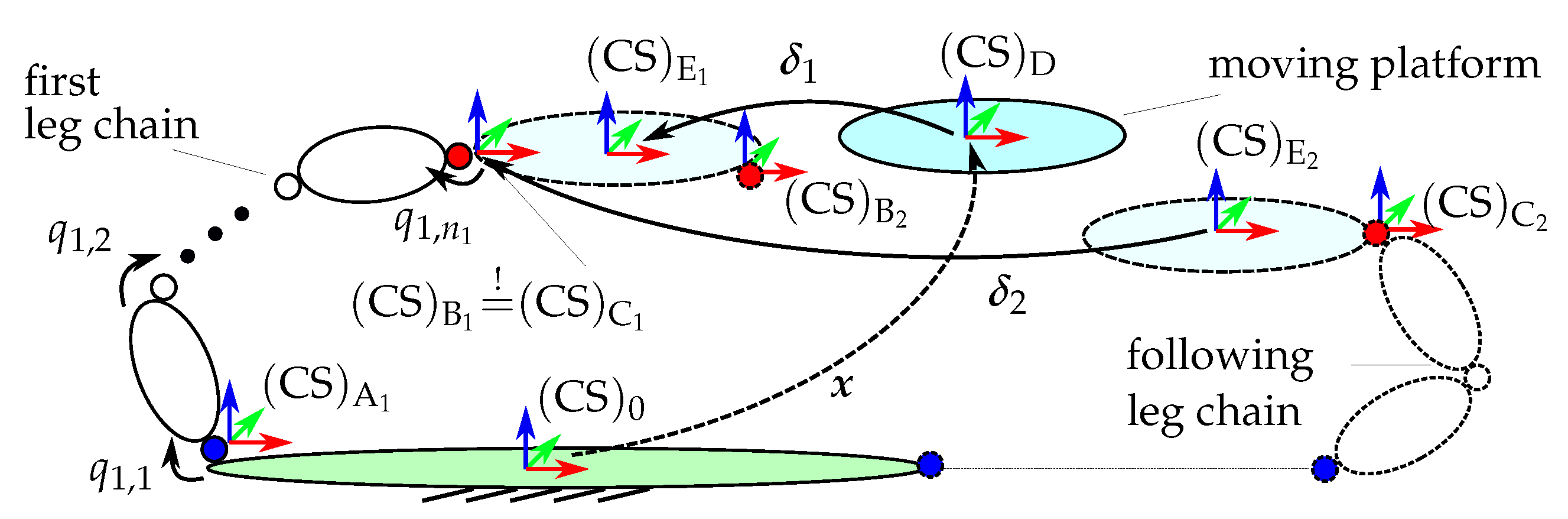
Figure 2.
Possibilities for distribution of joint DoFs among the m leg chains of a parallel robot with platform DoFs based on the CGK criterion with exemplary motion pattern aTbR. Planar case (a) and spatial case (b) modified from [8, p. 30 f.], (c) additional overconstraint symmetric alignments.
Figure 2.
Possibilities for distribution of joint DoFs among the m leg chains of a parallel robot with platform DoFs based on the CGK criterion with exemplary motion pattern aTbR. Planar case (a) and spatial case (b) modified from [8, p. 30 f.], (c) additional overconstraint symmetric alignments.
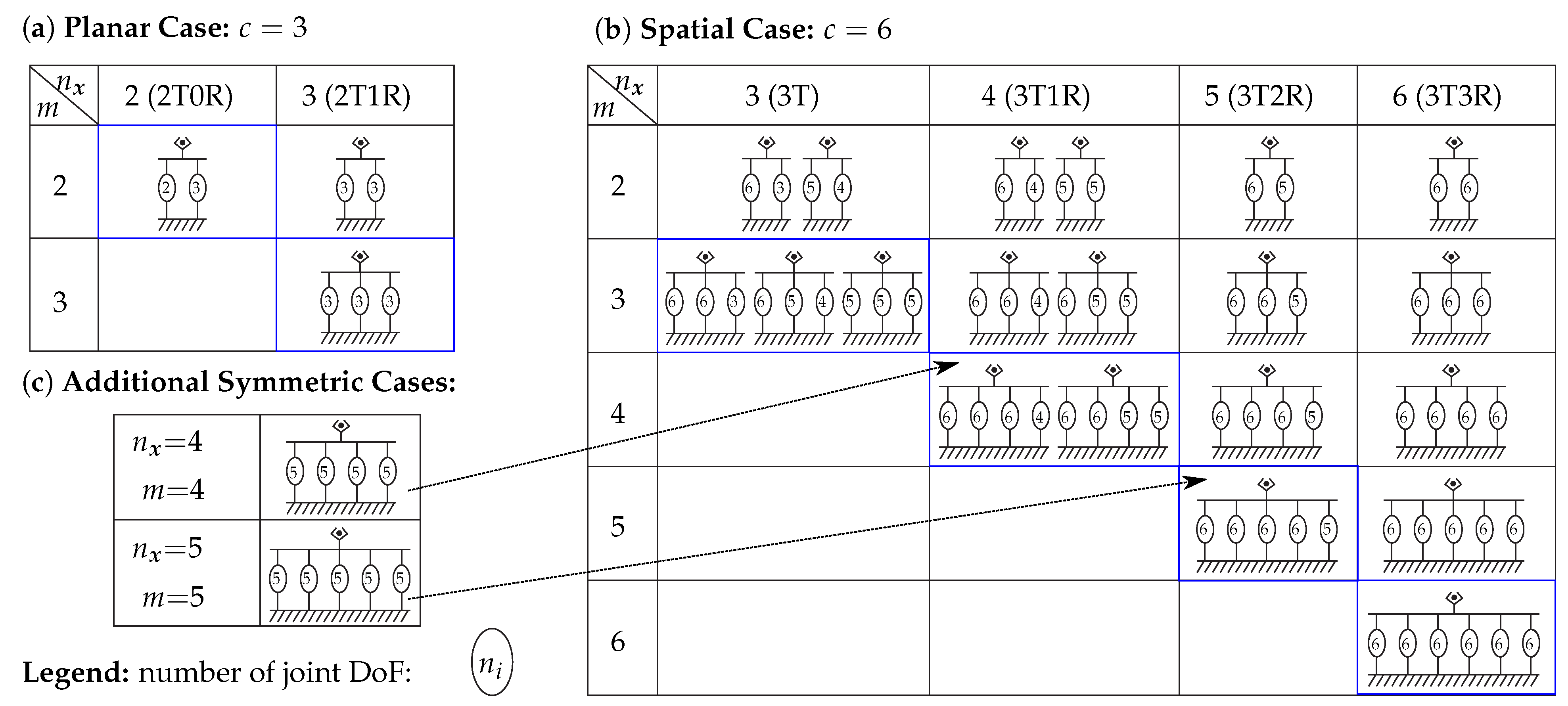
Figure 3.
Illustrative examples of structural synthesis results for 3T parallel robots. Mod. from [28, Figure 9.14–9.15] (a–b), [5, Figure 6.10a] (c), [35, Figure 4.30b] (d). The same accents on letters R (revolute joint) mark parallelism of the joints’ axes by R̀ or Ŕ.
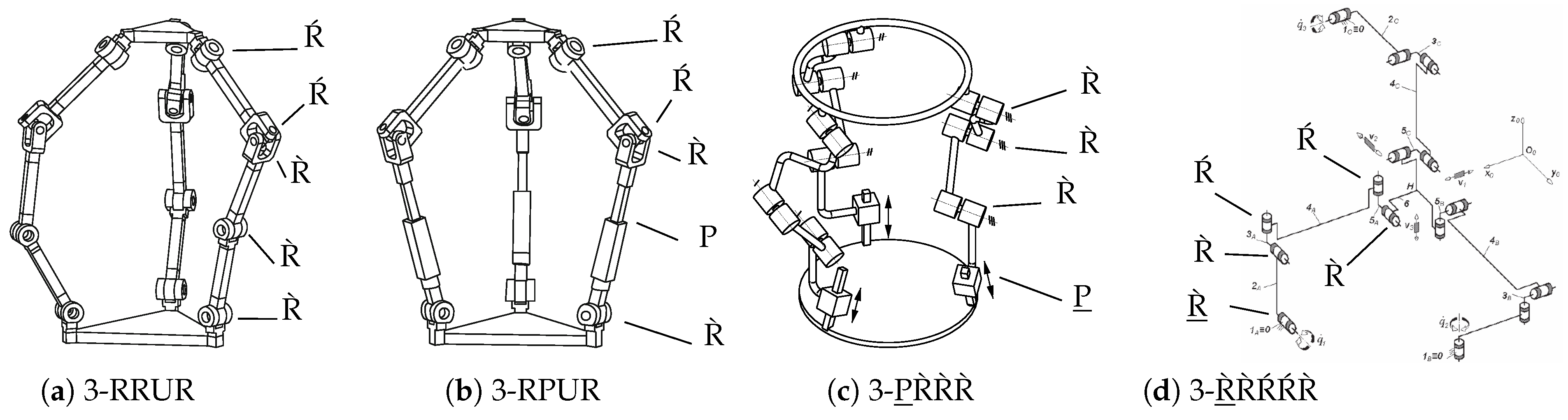
Figure 4.
Parallel robot from [30] with annotation of geometric structural entities. Previously published in [10] (under CC-BY License)
Figure 4.
Parallel robot from [30] with annotation of geometric structural entities. Previously published in [10] (under CC-BY License)
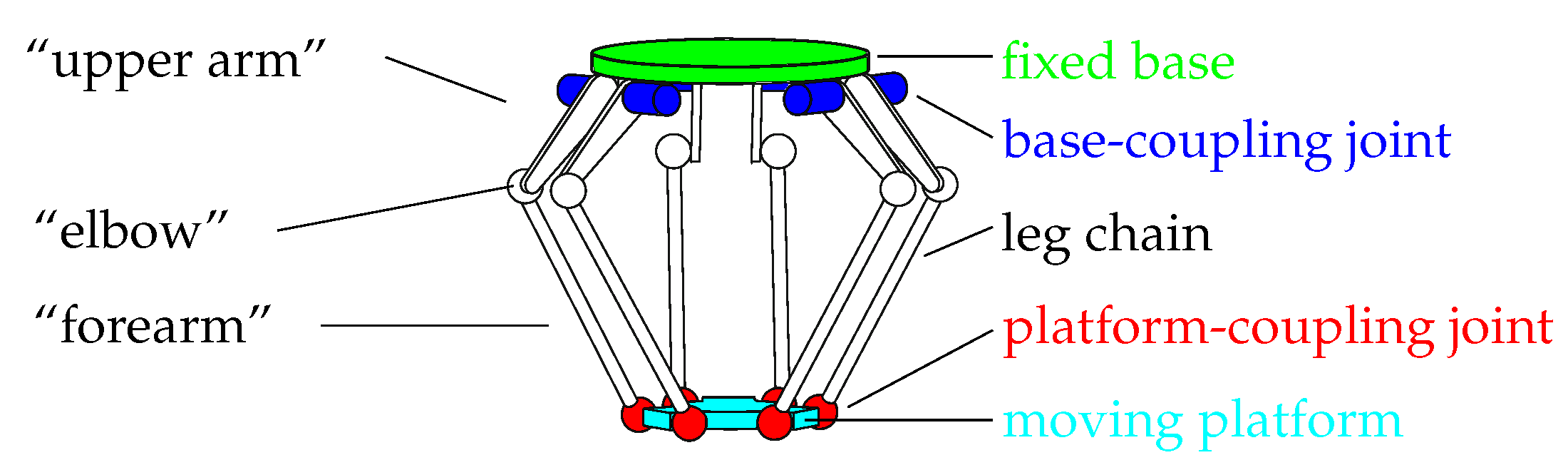
Figure 5.
Flowchart of the structural synthesis of Section 3
Figure 5.
Flowchart of the structural synthesis of Section 3
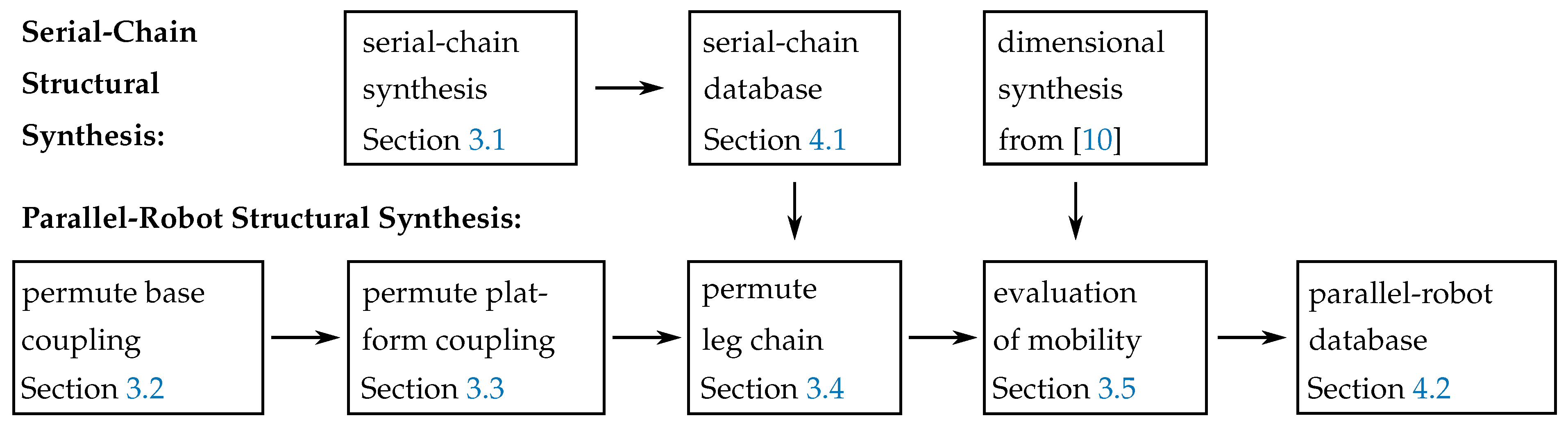
Figure 6.
Geometric principles for circular alignments of the base-coupling joint with given coupling joint frame (the blue z-axis corresponds to first joint axis): (a) vertical (mod. from [Figure 9.10g] in [5]), (b) tangential (mod. from [Figure 9.14] in [28]), (c) radial (mod. from [47]), (d) conical ([Figure 9.10f] in [5]). Already published in [10] (under CC-BY License).
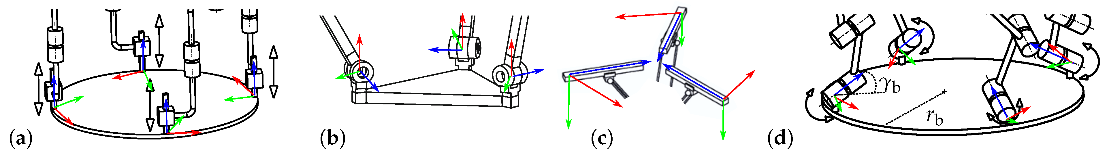
Figure 7.
Geometric principles for pairwise circular alignments of the base-coupling joint with given coupling joint frames: (a) Vertical (mod. from [Figure 2f] in [30]), (b) Tangential (mod. from [Figure 2a] in [30]), (c) Radial (top view on base), (d) Conical/pyramidal (source: Daniel Ramirez, LUH; mod). Already published in [10] (under CC-BY License).
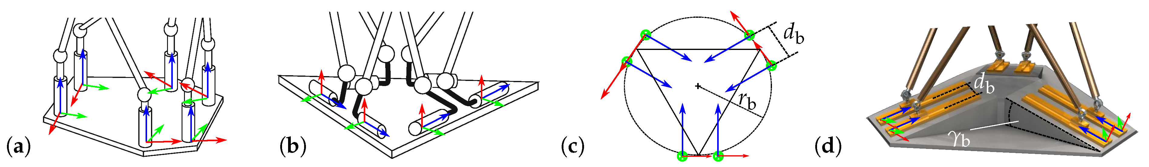
Figure 8.
Geometric principles for base-joint alignments of symmetric 3T2R parallel robots with given : (a) parallel in the base plane (mod. from [5, Figure 12.7a]), (b) vertical to the base plane with parallel second joints (mod. from [5, Figure 12.7b]).
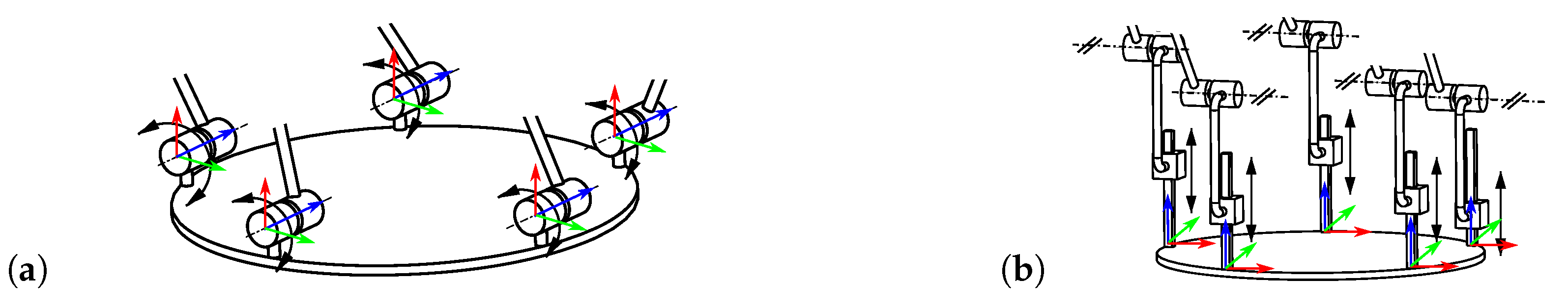
Figure 9.
Geometric principles for circular alignments of the platform-coupling joint with given : (a) vertical (mod. from [5, Figure 9.10b]), (b) tangential (mod. from [5, Figure 9.10g]), (c) radial (top view on platform).
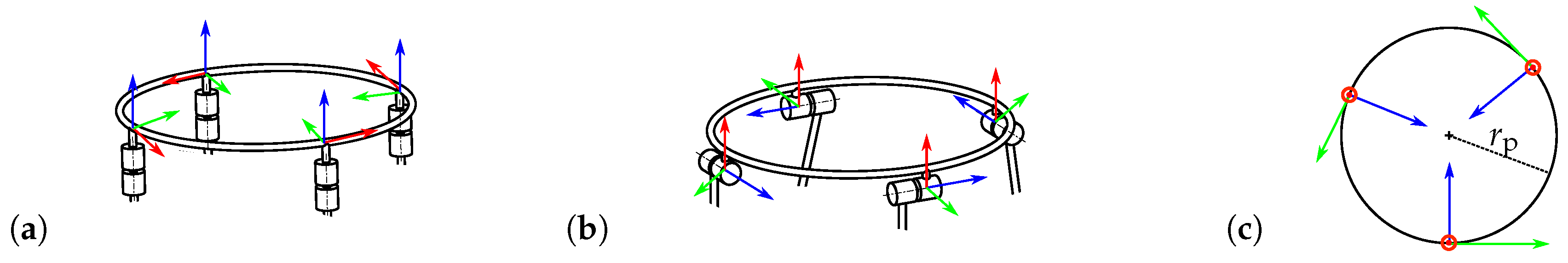
Figure 10.
Further geometric principles for circular alignments of the platform-coupling joint with given : (a) matching to the leg chain (mod. from [5, Figure 6.10a]), (b) parallel in the platform plane (mod. from [5, Figure 12.7a]), (c) conical (mod. from [28, Figure 9.14]), (d) tangential with inclination to the platform plane (mod. from [5, Figure 9.10d])
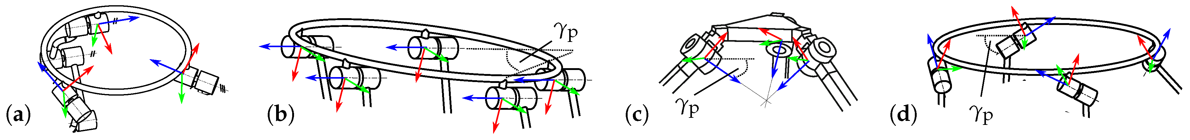
Figure 11.
Flowchart of the dimensional synthesis from [10] within the platform-mobility check
Figure 11.
Flowchart of the dimensional synthesis from [10] within the platform-mobility check
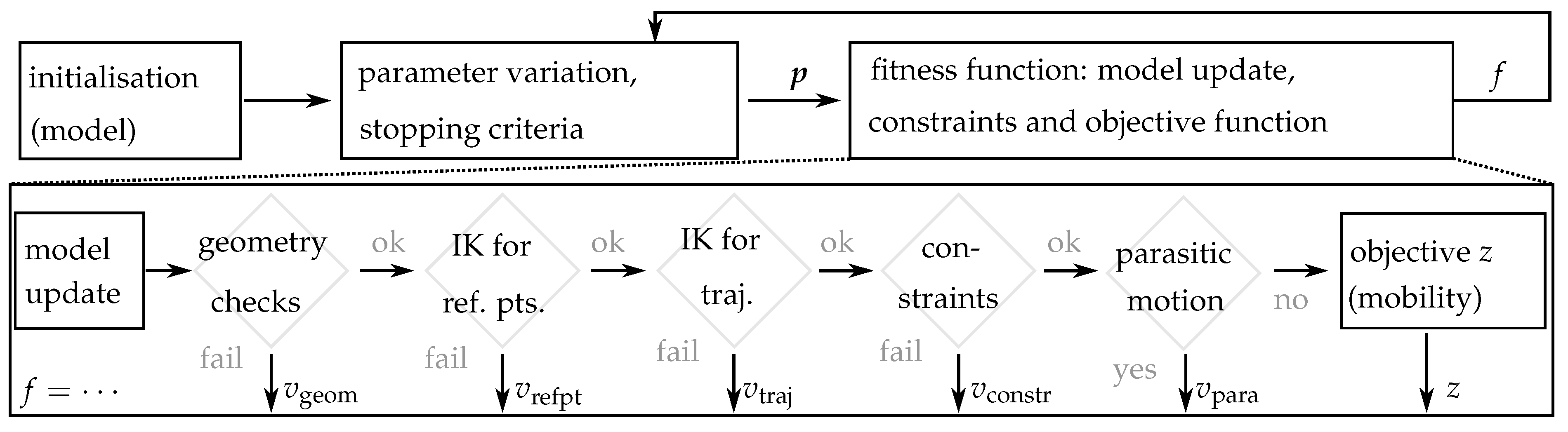
Figure 12.
Top view on the 3-RRR robot resulting from the dimensional synthesis within the reference trajectory, given by , , and in the world frame. Black lines mark the leg chains, red circles active joints, blue circles passive joints, and the cyan and magenta triangle marks the moving platform.
Figure 12.
Top view on the 3-RRR robot resulting from the dimensional synthesis within the reference trajectory, given by , , and in the world frame. Black lines mark the leg chains, red circles active joints, blue circles passive joints, and the cyan and magenta triangle marks the moving platform.
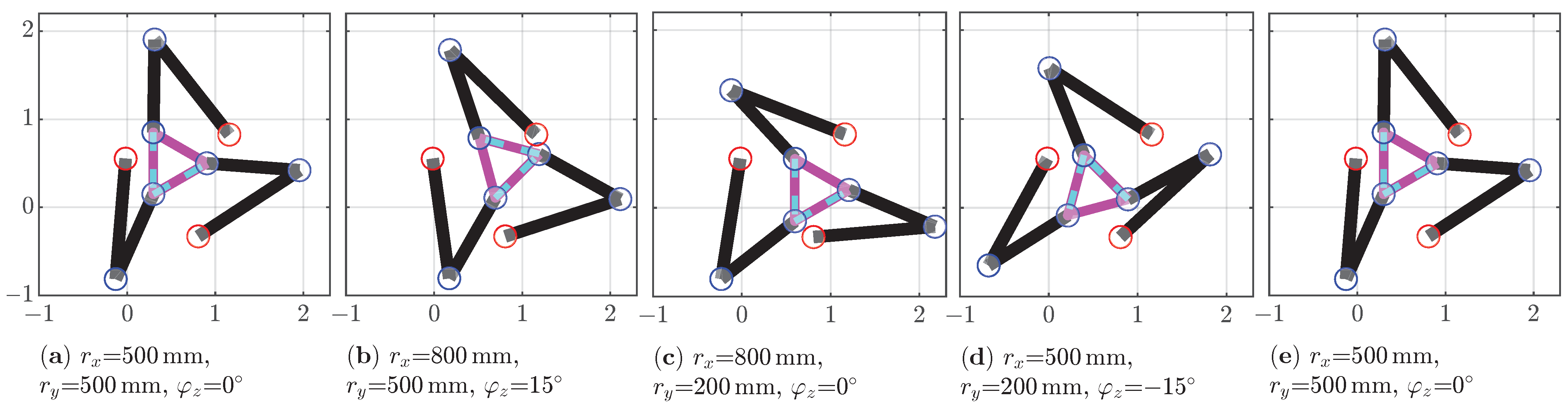
Figure 13.
Alignments of base and platform-coupling joints for the 3-P̀R̀R̀R̀ parallel robot (PR 1.1)
Figure 13.
Alignments of base and platform-coupling joints for the 3-P̀R̀R̀R̀ parallel robot (PR 1.1)
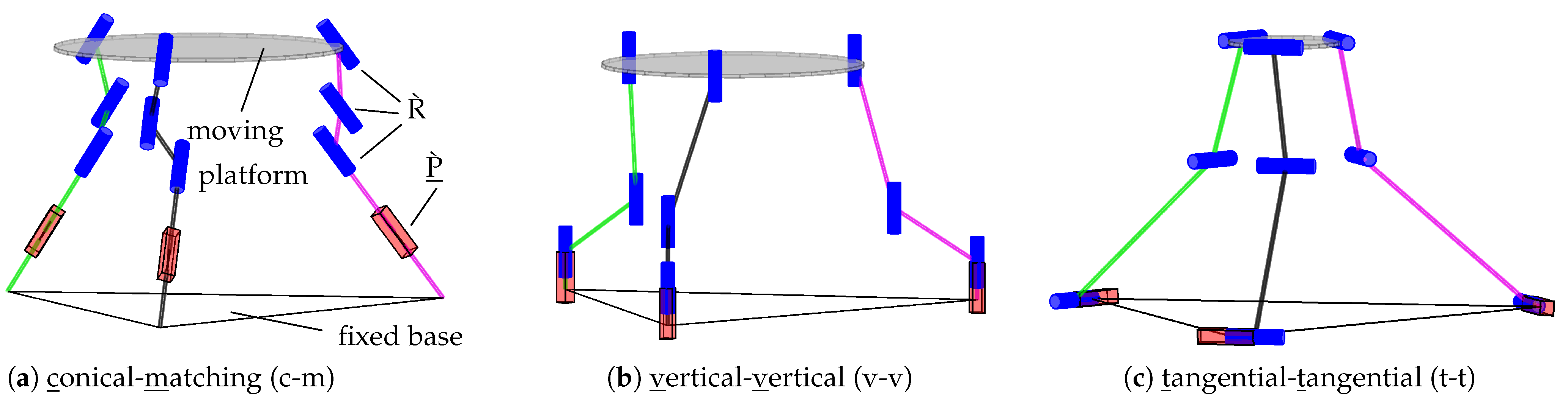
Figure 14.
Further examples of synthesis results of 3T parallel robots from Table 10
Figure 14.
Further examples of synthesis results of 3T parallel robots from Table 10
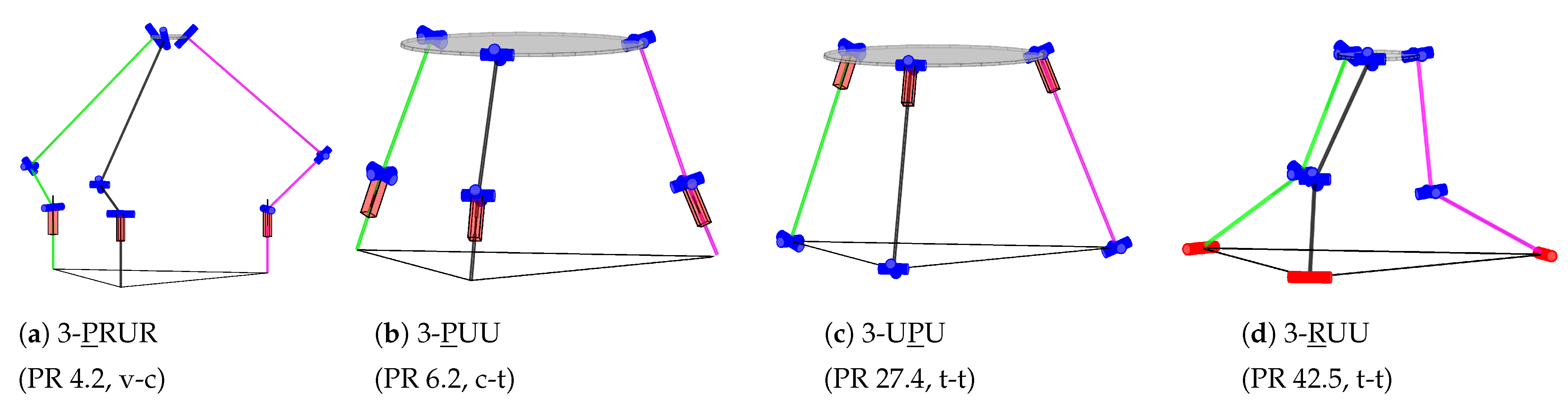
Figure 15.
Examples of synthesis results of 3T1R parallel robots
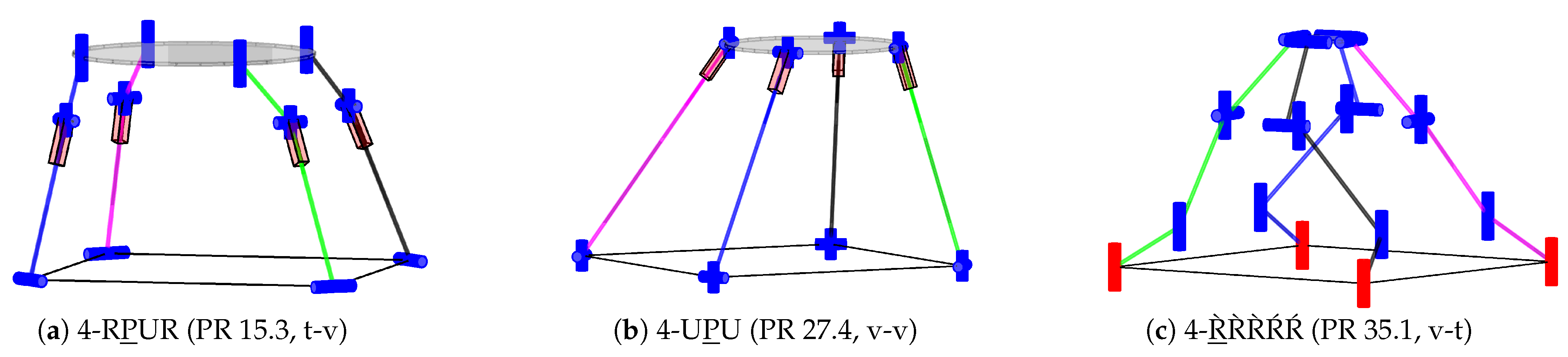
Figure 16.
Alignments of base- and platform-coupling joints for the 5-PR̀R̀ŔŔ parallel robot (PR 3.2)
Figure 16.
Alignments of base- and platform-coupling joints for the 5-PR̀R̀ŔŔ parallel robot (PR 3.2)
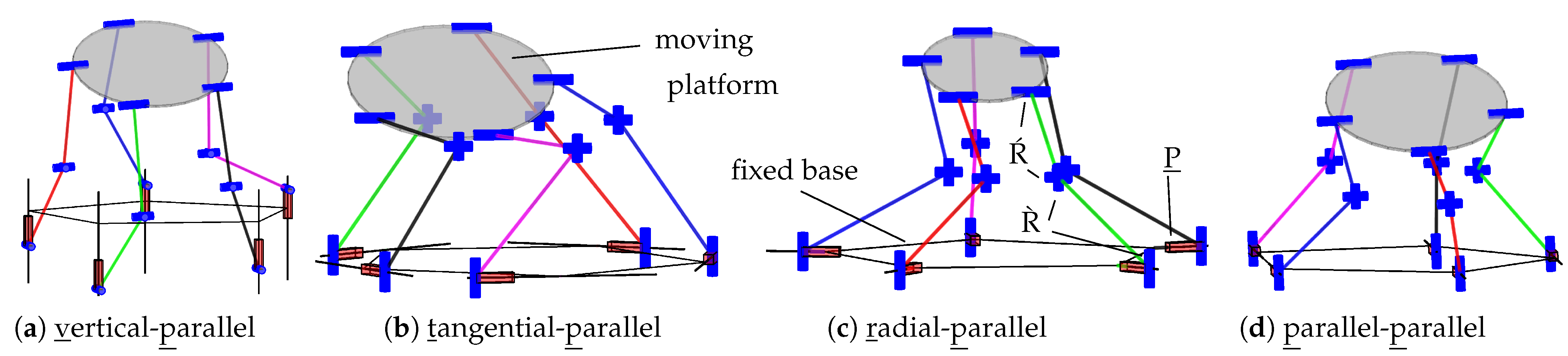
Figure 17.
Further examples of synthesis results of 3T2R parallel robots from Table 12
Figure 17.
Further examples of synthesis results of 3T2R parallel robots from Table 12
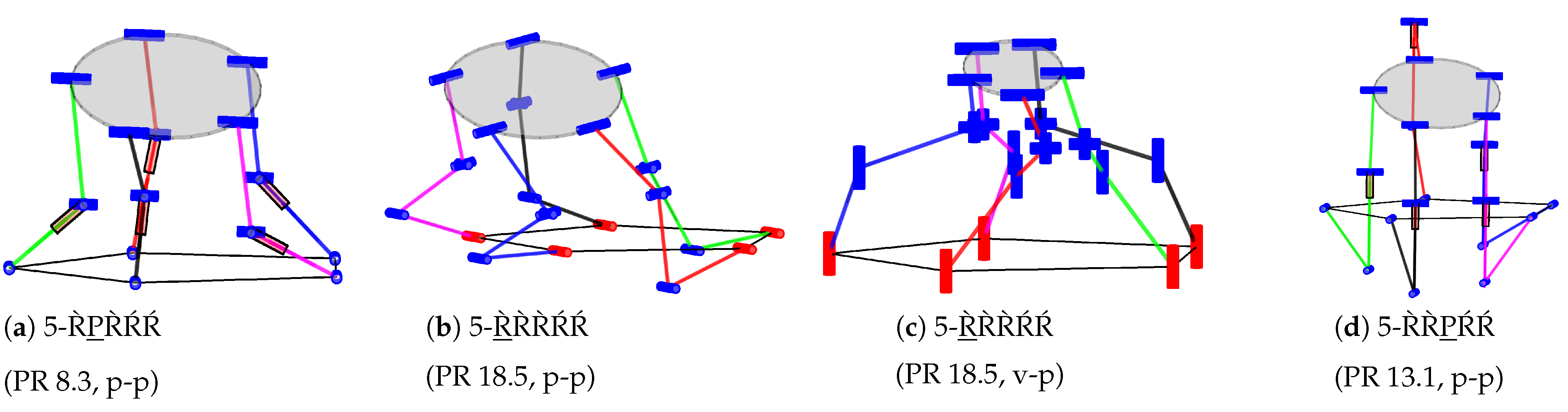
Figure 18.
Examples of synthesis results of 3T3R parallel robots with three joints per chain
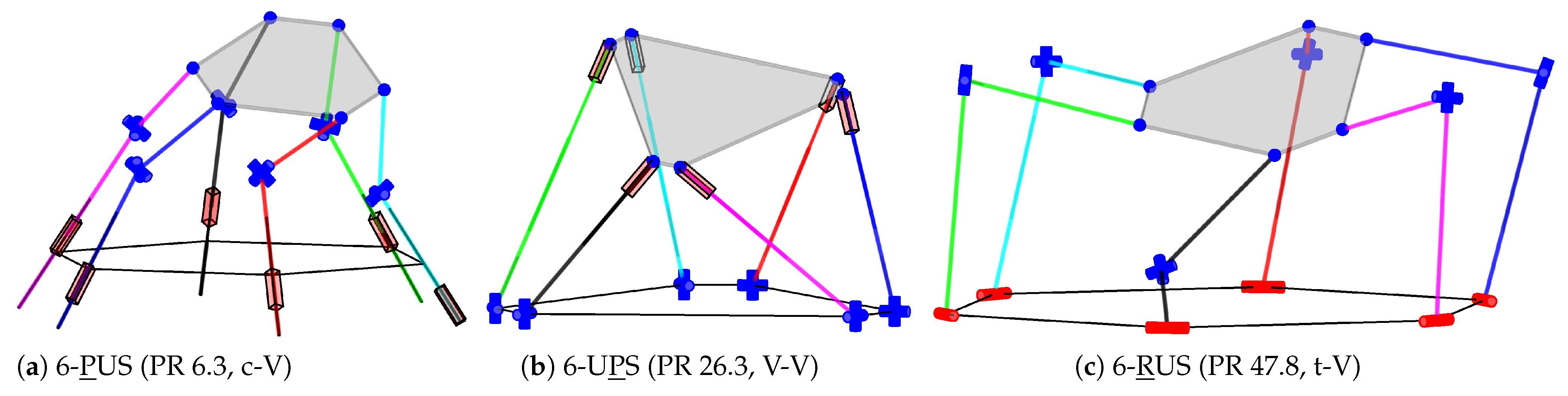
Figure 19.
Examples of synthesis results of 3T3R parallel robots with four joints per chain
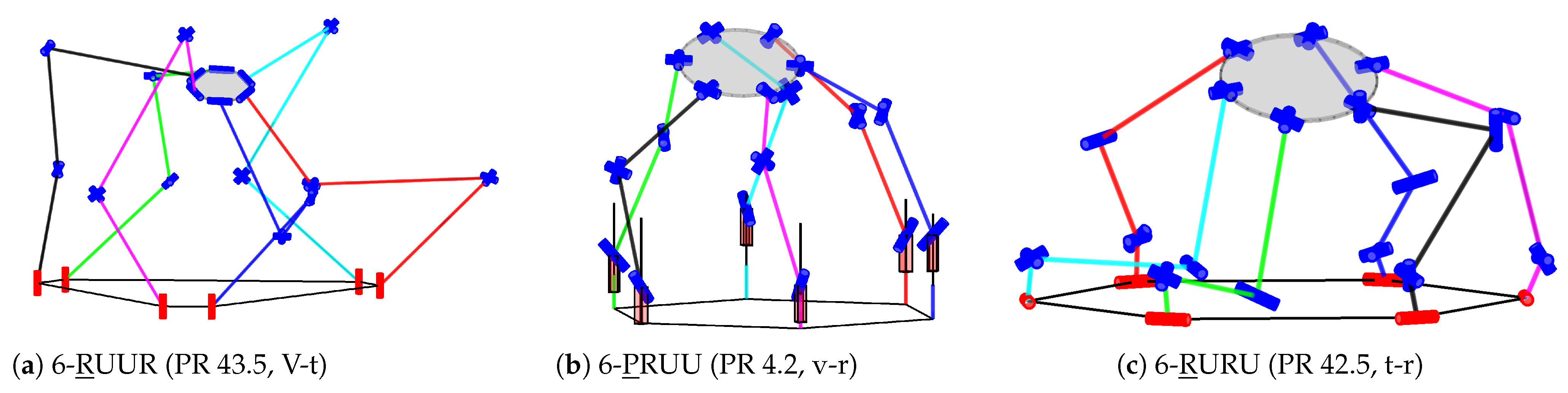

Table 1.
Correspondence of motion pattern and required velocity vector for cases from [27].
Table 1.
Correspondence of motion pattern and required velocity vector for cases from [27].
| Motion | 2T1R robot | 3T robot | 3T1R robot | 3T3R robot/ leg |
|---|---|---|---|---|
Table 2.
Summary of resulting numbers for symmetric 3T parallel robots from the state of the art. The added numbers refer to leg chains or assemblies of leg chains with three, four, or five DoFs.
Table 2.
Summary of resulting numbers for symmetric 3T parallel robots from the state of the art. The added numbers refer to leg chains or assemblies of leg chains with three, four, or five DoFs.
| Reference | Leg chains (3/4/5 DoF) | Assemblies (3/4/5 DoF legs) | Mechanisms |
|---|---|---|---|
| [28, p. 352 ff.] | not given | ||
| [5, p. 96 ff.] | 90 (one each) | 90 | |
| [35] | see [6, pp. 341–652] | not given | 295 |
Table 3.
Summary of resulting numbers for symmetric 3T1R parallel robots from the state of the art
| Reference | Leg chains (4/5 DoF) | Assemblies | Mechanisms |
|---|---|---|---|
| [28, p. 340 ff.] | 30 (one each) | not given | |
| [5, p. 141 ff.] | 132 (one each) | 11 | |
| [36] | see [6, pp. 377–652] | not given | 103 |
Table 4.
Summary of resulting numbers for symmetric 3T2R parallel robots from the state of the art
| Reference | Leg chains (5 DoF) | Assemblies | Mechanisms |
|---|---|---|---|
| [28, p. 337 ff.] | 10 | 10 (one each) | not given |
| [5, p. 185 ff.] | 27 | 27 (one each) | 2 |
| [6, pp. 445–636] | 249 | no dedicated book on 3T2R | |
| [42] | 29 | focus on asymmetric legs, only 5-PRUR | |
| [13] | 15 (excerpt) | no numbers given | |
Table 5.
Correspondence of motion pattern and required velocity vector for the leg-chain synthesis of parallel robots (PR), extending Table 1
Table 5.
Correspondence of motion pattern and required velocity vector for the leg-chain synthesis of parallel robots (PR), extending Table 1
| Motion | 3T PR leg | 3T1R PR leg | 3T2R PR leg | 3T2R robot |
|---|---|---|---|---|
| — | — | |||
| — | — |
Table 6.
Dimensional parameters for the base-joint alignments. Previously published in [10].
Table 6.
Dimensional parameters for the base-joint alignments. Previously published in [10].
| Position | Symmetric on Circle Circumference | Pairwise | ||||||
|---|---|---|---|---|---|---|---|---|
| Direction | v | t | r | c | V | T | R | C |
| Parameters | , | , | , | , | , , | |||
| Figure | 6a | 6b | 6c | 6d | 7a | 7b | 7c | 7d |
Table 7.
Dimensional parameters for the platform-joint alignments, noted by an abbreviation
| Position | symmetric on circle circumference | pairwise | ||||||||
|---|---|---|---|---|---|---|---|---|---|---|
| Direction | v | t | r | m | p | c | i | V | T | R |
| Parameters | , | , | , | , | , | r, | ||||
| Figure | 9(a) | 9(b) | 9(c) | 10(a) | 10(b) | 10(c) | 10(d) | |||
Table 8.
Structural synthesis results for leg chains with three joints
| # | Structure | Usage in PR# | Free parameters | Fixed parameters |
|---|---|---|---|---|
| 2T1R | ||||
| 1 | PR̀R̀ | 1 | , , , | °, |
| 2 | R̀PR̀ | 2 | , , , | °, |
| 3 | R̀R̀R̀ | 3 | , , , , |
Table 9.
Structural synthesis results for 2T1R parallel robots
| PR# | Structure | Joints | Leg# | Alignment |
|---|---|---|---|---|
| 1.1 | 3-PR̀R̀ | — | 1 | (t,r,p)-v |
| 2.1 | 3-R̀PR̀ | — | 2 | v-v |
| 3.1 | 3-R̀R̀R̀ | — | 3 | v-v |
| ....2 | 3-R̀R̀R̀ | — | v-v |
Table 10.
Examples of the 3T parallel-robot synthesis results from Table S4 (supplementary materials)
Table 10.
Examples of the 3T parallel-robot synthesis results from Table S4 (supplementary materials)
| PR# | Structure | Joints | Leg# | Fig. | Alignment |
|---|---|---|---|---|---|
| 1.1 | 3-P̀R̀R̀R̀ | — | 1 | 13 | c-m; R.D.: p-m, v-v, t-t, r-r |
| 4.2 | 3-PR̀R̀ŔŔ | PRUR | 3 | 14(a) | (v,t,r,c)-c, (v,t,r,c,p)-(v,t,r), (t,r,p)-p |
| 6.2 | 3-PR̀ŔŔR̀ | PUU | 5 | 14(b) | (v,t,r,c)-t, (v,t,r,p)-v, (v,c)-c, (v,t,r)-r, p-p |
| 27.4 | 3-R̀ŔPŔR̀ | UPU | 28 | 14(c) | v-v, t-t, r-r |
| 42.5 | 3-R̀R̀ŔŔR̀ | RUU | 50 | 14(d) | v-v, t-t, r-r |
Table 11.
Examples of the 3T1R parallel-robot synthesis results from Table S5 (supplementary materials)
Table 11.
Examples of the 3T1R parallel-robot synthesis results from Table S5 (supplementary materials)
| PR# | Structure | Joints | Leg# | Fig. | Alignment |
|---|---|---|---|---|---|
| 15.3 | 4-R̀PR̀ŔŔ | RPUR | 13 | 15(a) | (t,r,p)-v, v-p; R.D.: v-(t,r) |
| 27.4 | 4-R̀ŔPŔR̀ | UPU | 28 | 15(b) | R.D.: v-v |
| 35.1 | 4-R̀R̀R̀ŔŔ | — | 45 | 15(c) | (t,r,p)-v, v-(t,r,p) |
Table 12.
Examples of the 3T2R parallel-robot synthesis results from Table S6 (supplementary materials)
Table 12.
Examples of the 3T2R parallel-robot synthesis results from Table S6 (supplementary materials)
| PR# | Structure | Joints | Leg# | Fig. | Alignment |
|---|---|---|---|---|---|
| 3.2 | 5-PR̀R̀ŔŔ | PRUR | 3 | 16 | (t,p,v)-p; R.D.: r-p |
| 8.3 | 5-R̀PR̀ŔŔ | RPUR | 8 | 17(a) | p-p |
| 13.1 | 5-R̀R̀PŔŔ | — | 23 | 17(d) | (v,p)-p |
| 17.2 | 5-R̀R̀ŔPŔ | RUPR | 36 | – | p-p |
| 18.5 | 5-R̀R̀R̀ŔŔ | RRUR | 45 | 17(b–c) | (v,p)-p |
| 19.5 | 5-R̀R̀ŔŔŔ | RURR | 46 | – | R.D.: (v,p)-p |
Table 13.
Examples of the 3T3R parallel-robot synthesis results from Table S7 (supplementary materials)
Table 13.
Examples of the 3T3R parallel-robot synthesis results from Table S7 (supplementary materials)
| PR# | Structure | Joints | Leg# | Fig. | Alignment |
|---|---|---|---|---|---|
| 6.3 | 6-PRRRRR | PUS | 6 | 18(a) | (v,t,r,c,V,T,R,C,p)-(v,V) |
| 26.3 | 6-RRPRRR | UPS | 26 | 18(b) | (V,T,R,C)-v, (v,t,r,c,V,T,R,C,p)-V; R.D.: (v,t,r,c,p)-v |
| 43.5 | 6-RRR̀R̀ŔŔ | RUUR | 43 | 19(a) | (v,t,r,c,V,T,R,C,p)-(v,t,r,V,T,R,p) |
| 47.8 | 6-RRRRRR | RUS | 47 | 18(c) | (v,t,r,c,V,T,R,C,p)-(v,V) |
Table 14.
Computation time of the dimensional synthesis in the structural synthesis
| motion | permutations | rank checks | check failed | sum | ||||
|---|---|---|---|---|---|---|---|---|
| pattern | ||||||||
| in min | in min | in h | ||||||
| 2T1R | 9 | 3 | 6 | 6 | 0.1 | 0 | – | 0.0 |
| 3T | 22102 | 14643 | 7459 | 1029 | 12.2 | 6430 | 26.3 | 3022.7 |
| 3T1R | 19169 | 11642 | 7527 | 591 | 11.3 | 6936 | 30.3 | 3609.0 |
| 3T2R | 11019 | 7942 | 3077 | 77 | 18.3 | 3000 | 139.7 | 6807.9 |
| 3T3R | 59800 | 43265 | 16535 | 15225 | 2.9 | 1310 | 28.0 | 1156.0 |
| Sum | 112099 | 77495 | 34604 | 16928 | 3.9 | 17676 | 45.8 | 14595.6 |
Disclaimer/Publisher’s Note: The statements, opinions and data contained in all publications are solely those of the individual author(s) and contributor(s) and not of MDPI and/or the editor(s). MDPI and/or the editor(s) disclaim responsibility for any injury to people or property resulting from any ideas, methods, instructions or products referred to in the content. |
© 2025 by the authors. Licensee MDPI, Basel, Switzerland. This article is an open access article distributed under the terms and conditions of the Creative Commons Attribution (CC BY) license (http://creativecommons.org/licenses/by/4.0/).
Copyright: This open access article is published under a Creative Commons CC BY 4.0 license, which permit the free download, distribution, and reuse, provided that the author and preprint are cited in any reuse.


