
Submitted:
17 April 2025
Posted:
18 April 2025
You are already at the latest version
Abstract
Triangular shapes have been studied from different perspectives over a wide temporal frame since ancient times. Initially, fundamental theorems have been formulated to demonstrate their geometrical properties. Philosophy and art leveraged the peculiar aspects of triangles as building blocks for more complex geometrical shapes. This paper will review triangles by adopting a multidisciplinary approach, recalling ancient science and Plato's arguments in relation to their connection with philosophy. It will then consider the artistic utilization of triangles, particularly in compositions created during the medieval era, as exemplified by the Cosmati Italian family's masterpieces. Various scientific environments have explored triangular 2D and 3D shapes for different purposes, which will be briefly reviewed here. After that, the Sierpinski geometry and its properties will be introduced, focusing on the equilateral shape and its internal complexity generated by subdividing the entire triangle into smaller sub-triangles. Finally, examples of triangular planar shapes that fulfill the Sierpinski geometry will be presented as an application in signal processing for high-frequency signals in the microwave and millimeter-wave range.
Keywords:
triangles
; philosophy
; artistic triangular decorations
; Sierpinski
; microwaves
; millimeter waves
; planar components
; antennas
1. Introduction
This paper reviews the meaning of triangles from different perspectives, including mathematics, philosophy and art, and discusses the applications of triangular shapes as resonating elements for microwave planar components and antennas.
Numbers initially motivated the Greek philosophers and mathematicians, trying to reduce the world’s interpretation to specific numeric combinations and geometrical shapes. From this point of view, the triangles were one of the focal points of the mathematical and philosophical efforts of Pythagoras and Plato, originating the famous theorems and the dialogue called Timaeus [1,2,3,4]. Sierpinski also published about Pythagorean triangles in [5]. Of course, the number “3” is also related to triangles because of the three edges of the geometrical figure. It has been invoked for reasons pertaining to its magic and religious nature, encompassing Catholic culture and several examples since the early historical ages.
In many ancient traditions, “3” is the counterpart to “4”, comparing the male and female principle or the complementarity of the sky and the earth. The number “4” has also been related to the four essential elements studied in the early stage of philosophy and science, i.e., water, air, earth, and fire. “3”+”4” originated the number “7,” also considered “magic” for other reasons (one-fourth of the lunar cycle; the so-called “planets” of antiquity, including the moon and sun, the Pleiades, etc.). [6].
Concerning art, reutilizing small marble pieces coming from the destruction of old Roman temples, mainly columns and wall or floor slides, a medieval Roman family of marble workers invented the so-called Cosmatesque style, whose products are visible in many catholic churches in Italy, but sometimes also abroad [7,8,9]. Geometrical representations with squares, circles, or spirals were manufactured from the XI to the XIII Century by the Cosmati family, and triangles were available in many compositions as building blocks of picturesque wide floors looking like mosaics. More ancient manufactures are available in other places. It is interesting to see a handmade decoration from the Museum of Malta, La Valletta, which can be considered a preliminary fractal geometry (see Figure 1).
The Sierpinski triangles are figures belonging to the more general group of fractals [10,11]. They are obtained by a progressive subdivision of whole triangles into many internal triangles of decreasing size. From a mathematical point of view, many publications, software tools, and potential applications have been considered in the past decades [12,13,14,15,16]. Triangles are possible elementary cells in the finite element method (FEM) of calculation for electromagnetic 2D and 3D simulations, where each side can represent a lumped element [17]. They are building blocks in manufacturing processes like 3D printing, contributing to mechanically stable structures, especially when combined in hexagons [18].
Finally, equilateral triangles can be seen as regular shapes resonating at specific frequencies when adequately sized and excited by a feeding system. A key point about resonators and antennas for high frequencies is the feeding network necessary for obtaining an effective resonant response and good radiative performance for the antennas. This is especially important when the triangles are characterized by an additional internal complexity, as the Sierpinski geometry [19,20]. Like any other resonator, the coupling degree (electrical matching) determines the quality factor and bandwidth. In the case of planar components or antennas, the specific difference between them is the necessity for substrates compatible with the manufacturing processes for electronic components (high dielectric constant) or radiative elements (low dielectric constant). In both cases, the intrinsic frequency is determined by the size and the substrate choice. Moreover, triangles are building blocks suitable for applications in resonating or radiative arrays, properly combining several of them [20].
In this paper, the triangle is presented from a complementary viewpoint rather than applications, and some configurations inspired by the Sierpinski geometry will also be proposed for specific configurations in high-frequency signal processing.
2. Philosophy, Mathematics and Art
Early philosophical currents have always considered mathematics and geometry interrelated and able to bring an inner meaning to understanding the natural order through symbols and specific shapes. This initial thinking was usual when no specialization was present among the scientific disciplines, and ancient thinkers had an intermediate profile between science and philosophy, trying to propose a unitary vision of the world based on general concepts linked to many knowledge fields, like astronomy and basic mathematics. Such a holistic vision of the world is also typical of oriental philosophy, but in that case, another, more spiritual approach is pursued. In ancient Greece, a logical and scientific methodology puzzled the scientists and philosophers, who were able to open schools with the ambition to select people able to understand matters considered “esoteric”, i.e., reserved to a selected group of students. This definition has nothing to do with other currents inspired by the magic meaning of numbers and shapes, which was trendy, especially in the XIX century.
2.1. Plato
The Timaeus essay of Plato, dating back to 360 B.C., treats the triangle as a building block figure originating solid figures. His understanding of reality was based on the World of Ideas and Forms, such that the original theory of the four elements evolved considering the presence of basic shapes, which are regular geometrical solids: Tetrahedron (fire), Octahedron (air), Icosahedron (water), and Cube (earth). Following this approach, the shapes correspond one by one to the four fundamental elements introduced in previous times to model reality. All the natural manifestations resemble their counterparts in the World of Ideas, with the possibility of exchanging their nature and being transformed into another shape. This way of proceeding preludes to the development of alchemy during the Renaissance period, to study the possibility of transforming basic materials into noble ones. The typical goal was to start from the lead to obtain gold, using one of the properties of the so-called philosopher’s stone [21]. Paracelsus was one of the most famous alchemists, introducing new concepts and materials even in toxicology [22]. Without forcing the comparison, we can say that the intuition of Plato, and successively that of the Alchemists, also preludes to modern findings, with chemical and nuclear reactions able to get different elements from proper initial conditions, energy, and involved elements or materials. To be noticed that the term “alchemical” is still used to indicate a process during which the chemical species is transformed into another via a pathway of nonphysical (alchemical) states, as discussed in [23,24] concerning free energy calculations. The Arab alchemist Jabir ibn Hayyan is considered one of the first to link the four elements to Alchemy, a term derived from the Arab language meaning “chemistry”. In ancient times, Aristotle introduced the principles of heat or cold and dryness or moisture, relating them to the four basic elements. In the historic alchemical approach, dating mainly to the so-called Renaissance period (15th-16th century), the reason for using triangles was to indicate the preferred direction of the four basic elements. So, air and fire are described by triangles pointing upward, while water and earth are symbolized by triangles pointing downwards. In particular, the triangles representing earth and air are plotted with a line bisecting the triangle, as it is shown in Figure 2 [25].
Back to Plato, his perfect polyhedral shapes comprise triangular faces with internal angles of 30-60-90 and 45-45-90 degrees, respectively. In detail, half of a square and half of an equilateral triangle are considered by Plato to be the fairest geometrical figures, able to originate all the others. See, for instance, [26]. An interesting recent book about ancient mathematics, including Plato’s approach to philosophy using geometry, is [27]. That book underlines that studying ancient mathematics means forgetting about analytical developments, as this kind of formalism is a recent advancement. Formulas cannot be immediately applied to geometrical and physical scenarios that only now have a synthetic representation using equations. Sometimes, it is questionable even to translate the Greek term “ἀριϴμoν” with “number”. In [27] it is also remembered that Plato defined God as a Geometer, citing other authors who claimed the role of God as a mathematician. The above consideration exemplifies a well-known phenomenon in previous times when philosophy and science were part of a unique discipline, sometimes mediated by religious aspects. In Plato’s case, his personal growth was mainly in philosophy, first as a student of Socrates and after that following a personal path proposing his approach to an ideal State. Returning to Athens after long periods spent in Sicily with tyrants Dionysius I and II, he founded Academia, inviting high-level students with different backgrounds, including mathematics. He was so enthusiastic about mathematics that he mixed that matter with his philosophical interests, giving origin to an original theory to use special triangles to obtain 2D and 3D polygons and linking ideal shapes to the abovementioned four basic elements. It is sometimes difficult to translate correctly an ancient text that has been written colloquially, and nowadays, there are still doubts about an authentic interpretation of Plato’s texts. The complete picture of Plato’s philosophical approach to nature includes the presence of a Demiurge, i.e., an alternative definition of a God that is not a Creator but a superior entity putting order using pre-existent elements. From this point of view, the Platonic Solids are building blocks linked to the four basic elements, plus the presence of a fifth one, considered later in the Medieval Age and defined as a quintessence, identified with the dodecahedron. A description of the Platonic Solids and their relationships with fire, air, water, and earth can be found in the original essay of Johannes Kepler [28], and it is reproduced in Figure 3.
Using a simple geometrical approach, all the 2D polygons can be subdivided using triangles (equilateral, rectangular, and isosceles). A triangle can be used as a building block for creating 2D polygons and, in the limit for a small angle α in the upper corner (or vanishing length s of the circular sector), a circle. An example of this construction is shown in Figure 4.
The same procedure can be applied to 3D figures using a tetrahedral pyramid, i.e., a polyhedron that connects a polygonal square base and the apex. In this case, we can even produce a sphere for the same limit conditions, considering a volumetric extension of the infinitesimal pyramid.
An interesting paper about art and mathematics discussing the Platonic solids in this framework is given in [29]. It is also stressed that the number of regular polygons is infinite, but the number of regular solids is finite.
It is worth noting that Plato’s approach was affected by an error, as Johannes Müller von Königsberg (1436–1476), better known as Regiomontanus, has demonstrated and discussed in [30]. Using a more precise demonstration, not affected by the understandable approximations of the initial approach, probably due to the utilization of not-perfect wood models, we can conclude that an approximately 7° angle is still needed to complete a solid figure using only tetrahedra.
2.2. Ancient Art and Cosmatesque Decorations
In the introduction, it was underlined that despite their symbolic meaning, triangles are part of many artistic decorations. Crossing lines was probably one of the initial ways humans created shapes, together with other preliminary techniques, continuing with artistic hunting scenes and everyday life pictures in the caves. After that, many authors have used numbers and shapes with specific intents over the centuries [31,32], with alchemical meanings or indicating that you belong to a group. The triangle is the Catholic symbol that means the triple God identity (Father, Son, and Saint Spirit). That symbol, with the same meaning, is even used in the American one-dollar banknote.
After the fall of the Roman Empire, several ancient buildings were destroyed by external populations, conquering the previous domain of Rome. Marbles from the Mediterranean area, initially used for columns, floors, and walls in buildings belonging to the emperor and rich families, were abandoned and no longer maintained. Then, pieces of precious marble could be reutilized in decorative items, arranged in fragments, and proposed in original designs. In this framework, the Cosmati family developed a style based on geometrical configurations, primarily used for church floors, in response to the Pope’s requirements [33]. A mathematical approach, accompanied by a detailed description of Cosmatesque triangles and carpets, is interpreted using the Sierpinski theory, as presented in [34,35]. A few examples of Cosmatesque representations, including Sierpinski triangles, are shown in Figure 5 from the Roman church “San Lorenzo fuori le mura” (San Lorenzo outside the walls), but several other examples can be easily found, where triangles are used as the main shape or are part of a more complicated figure, like in Figure 6 and Figure 7. Another classic example of Cosmatesque art is in the Saint Nilo Abbey (an orthodox church with Christian rite, in Grottaferrata, a small town very close to Roma), as it is shown in Figure 8. From all of these examples, it is evident that triangular shapes have sometimes an inner meaning, like indicating a direction to be followed, or they are just an easy geometrical shape to be produced from the original pieces.
2.3. Other Cultural Environments Using Triangles
Several other fields, both scientific and non-scientific, utilize triangles for various purposes. In psychology, Robert Sternberg from Cornell University developed the triangular theory of love to explain passion, intimacy, and commitment as building blocks in human relationships [36].
Several examples of triangular arrangements of stars and planets are found in astronomy. Even if we know that constellations do not exist, in the sense that sometimes we see a specific shape using stars that only apparently belong to the same group or are close to each other, in some cases a “conjunction” can be claimed using the positions of planets and satellites as we see them from the Earth. In many instances, it is rare to see a triangular geometry involving planets, stars, and satellites, as is the case with the moon and planets within the solar system. An example is from the National Geographic Magazine in [37], where the Moon-Jupiter-Venus conjunction is photographed in a triangular configuration, whose next appearance will be in 2040.
Triangles can be illusions, like the Kanisza triangle, which is the result of an elaboration of our mind, but a real triangle does not exist. The above case is part of the general topic about illusory contours, i.e., the figures resulting from boundary conditions that lead the observer to the conviction that a specific shape is present even when it is not plotted [38].
Additionally, a triangular shape is used in other scientific contexts, which are also quite distinct. A typical example is the prism utilized in optics to decompose the spectrum of visible light into the wavelengths that originate the colors of a rainbow. Another example is using a triangular diagram to study the equilibrium state of a compound formed by three different chemical species in the right thermodynamic conditions for temperature and pressure, which is helpful in material science and medical applications [39].
A relatively new result for using triangular shapes is in manufacturing processes based on 3D printing to enhance a structure’s mechanical properties [40].
3. Mathematics and Geometry of Sierpinski Fractals
Triangles are categorized into distinct groups based on their shape. Equilateral, isosceles, and rectangular triangles are all suitable for arrangement in a more complicated planar structure. Still, the equilateral ones are easier to subdivide and combine in an array, especially for applicative purposes.
Sierpinski triangles can be considered a fractal geometry derived from creating a series of internal triangles with decreasing size. Starting from the initial one, you can subdivide it by considering empty or full triangles and a frame with a specific thickness surrounding all the created sub-triangles. Independent of the above choice, the following Equation (1) describes the total number of triangles created by the internal subdivision:
where n is the complexity level, and Nt is the number of sub-triangles generated. So far, n=0 means an entire single triangle, and n=1 means three sub-triangles plus an empty triangular shape, and so on. The situation is represented in Figure 9, where, for completeness, Sierpinski triangles are shown by creating holes in the usual way or the complementary one. As an example related to high frequency engineering, the generation of Sierpinski triangles for the design of antennas using neural networks was considered in [41]. The “negative” subdivision is complementary and gives back empty triangles surrounded by a frame. Choosing “positive” or “negative” (empty) sub-triangles is crucial in specific applications, such as high-frequency signal processing. It corresponds to a metalized or empty area photolithographically obtained onto the substrate.
Nt = 3n,
Sierpinski’s contribution was essential in obtaining a mathematical approach to formalize a theory supporting this specific shape, even if this geometry was already known, as discussed before, for different reasons. Since then, a mathematical formulation of the number of positive and negative sub-triangles and the area as a function of the internal complexity is available. In particular, the complexity level generates several internal sub-triangles, whose number is defined through Equation (1), with side length decreasing as 1/2n, a total perimeter going to infinite, and area vanishing when n grows. P=3n+1/2n gives the perimeter for a triangle with unitary edge length, while the area is A=(3/4)nA0, where A0=√3/4. These simple rules can be used to verify their consistency with a possible general law that predicts the frequency of resonance in high-frequency resonators. Sierpinski triangles are typically considered to originate from an equilateral initial shape, but generalized approaches based on non-equilateral shapes are also available [42].
4. High Frequency Applications
The utilization of equilateral triangles and their fractal evolution, namely the Sierpinski ones, in antennas and resonators has been documented since the 1980’s of the past century, up to evolutions for carpet Sierpinski geometries [43].
Several configurations have been studied, including different feeding solutions, to capitalize on the unique characteristic that enables modulation of the geometry and the generation of multiple frequencies. Most of the literature is focused on the equilateral triangle, but modifications are suggested to calibrate the frequency and control the spectrum. This task is not trivial because the analytical approach to predicting the resonance frequency is already complex, and electromagnetic simulations must often be used to support it for a direct comparison. The primary challenge is accounting for a structure that presents three significant electromagnetic discontinuities in the simple triangle and an increasing complexity when internal figures are introduced. For this reason, some papers are missing the spectra, probably because they match the expected resonances but are poorly excited [44]. In other papers, it was possible to make a comparison using simulations and experiments, but not formulae [45]. To the best of my knowledge, only in [46,47] a numerical approach supported by measures was successful in the spectrum prediction. Most other papers discuss comparisons between different methods, but they are often only occasionally supported by an experiment, even when suggesting valuable modifications to the original theory. An interesting approach is given in [48], and additional considerations can be found in [49,50,51].
4.1. Resonance Frequencies
Polygonal shapes and their resonance frequencies for microwave applications were studied decades ago with accurate electromagnetic field calculations. Microstrip-excited polygonal planar structures have been reviewed in [52], based, for the triangles, on the analytical developments in [53]. Triangles have been proposed initially with care for theoretical and experimental findings because they slightly improve the quality factor of resonators and may be utilized as magnetic materials with this specific shape for circulator applications [54,55]. The simulated contour of the electromagnetic field gives evidence for a higher value on the vertexes of the triangles; this finding suggests that the vertex could be the best place to feed a triangular shape for resonators and antennas, but we shall see that the general agreement with the first analytically derived mode is obtained with a lateral coupling, thus favoring the edge at least for the planar resonators. In contrast, the antennas require further study to achieve the optimal solution for the radiation properties of the configuration. Despite the efficiency of excitation at resonance, the modes excited in a triangular shape are obtained using well-established formulas that consider the indexes of the transverse magnetic and electric excitation modes. Three indexes must be defined, fulfilling the basic equation m+n+l=0, to solve the wave equation for the EM field components, where the abovementioned indexes are all related to field components and are not independent variables. The fundamental mode is described by the (1,0,-1) set of index values, from which the resonance wavevector value is k=4π/3a, where a is the edge length of the triangle. The resonance frequency of the fundamental mode is given by [44]:
where c is the light speed in vacuum and ε is the dielectric constant. From preliminary phenomenological evaluations about the necessity of introducing an effective size or an effective dielectric constant, it appeared that ε must not be corrected; while changing a with an effective value we get a more precise prediction of the resonating frequency [44]. Other modes can be excited, belonging to a series of resonances determined by the change of the indexes [45]. It should also be noted that the resonance frequency prediction is a theoretical result of the bare structure when the excitation is optimized, ensuring electrical matching. It is well known that feeding is critical for efficient coupling with the desired resonance mode; otherwise, a significant frequency shift and modifications to the band shape are experienced. In the following paragraphs, this item will be considered again for resonators and antennas. Like any other geometrical figure manufactured for planar high-frequency applications, a triangle is a structure with its resonance frequencies determined by size. Additional properties can be considered if magnetic materials, such as Permalloy [57] or the classical garnets and ferrites [58], or ferroelectric materials [59] are used for tunability. As discussed above, the feeding network is crucial for enhancing the antenna’s radiation capabilities. A reasonably accurate design procedure for triangular antennas and arrays is described in [52,60]. The reason for having a microstrip excitation on the opposite side of the antenna is the necessity of avoiding metal radiative contributions on the same side, especially for substrates with a lower dielectric constant, where the microstrip can be broad and comparable to the antenna size. Another contribution to predicting the resonance frequencies for Sierpinski antennas is given in [41]. The fractal dimension enables the creation of a multi-band response, which is enhanced compared to the simple triangle. A good review of fractal configurations useful for radiation and filtering applications is given in [61]. The internal complexity of the Sierpinski geometry or a combination in an array can also modulate the expected resonance frequency. Still, we shall see that it can affect other radiator properties [62].
4.2. Antennas
An example of the frequency response of the sequence from C0 to C3 (from the 0th to the 3rd iteration in the internal complexity) of a Sierpinski antenna is given in the simulations shown in Figure 10, where the substrate is a commercially available material Rogers 5880 (RO5880), with dielectric constant ε=2.2 and dielectric losses tanδ=0.0009 for frequencies higher than 10 GHz [65]. A low dielectric constant impedes the excitation of substrate modes, otherwise lowering the overall antenna performance. The substrate thickness has been fixed at d=1.575 mm, which is typical for commercially available ones. The metal thickness is t=35 µm, which is also better for power applications, and the antenna is grounded. A frame of 200 µm surrounds the entire structure and each sub-triangle. A bowtie configuration with an internal feeding has been chosen to show how the spectrum can be complicated by the internal sub-triangles of the antenna, whose feeding might be optimized depending on the frequency and the application. In Figure 10, the simulated configurations and the spectrum of the antennas are plotted, with evidence of a complicated response, with an increase in the number of the excitation modes as a function of the sub-divisions, even if identifying the modes to be compared is still subject to interpretation, as also the frequency shift appears to be not monotone with the internal complexity. The excited mode strictly depends on the coupling solution.
The radiation pattern at resonance exhibits a narrow lobe when measured in the middle of the two wings. It is broader in the 90° position, as shown in Figure 11 plot at resonance for C0, i.e., at approximately 26 GHz. The expected antenna gain is in the order of 7 dB. Qualitatively, the same radiation pattern is predicted for all the configurations at resonance. Nevertheless, better matching is obtained for C1, which exhibits a gain of around 7.8 dB at 20 GHz and enhanced sidelobes suppression, as shown in Figure 12. The presence of a substrate and the ground condition alters the response of the naked structure. Still, it is necessary to simulate a situation closer to the experimental one, where a feeding line should be present, and the ground helps improve the antenna gain.
Concerning the feeding network, having a line on the opposite side of the antenna helps vanish its contribution for radiation purposes, and the radiation and gain are related mainly to the antenna itself and not to the feeding lines. Moreover, the microstrip will be narrow if designed onto a substrate with a higher dielectric constant than the antenna. Two options can be used to excite the radiating element: a direct connection with a via hole or a slot. We shall see the simulation results using a via hole combined with a particular shape for the slot. The antennas previously studied with “internal ports” have been fed using a microstrip line designed onto a RO3006 substrate 254 μm thick, with ε=6.5. A via hole has been introduced to connect the microstrip to the center of the bowtie and the coupling between the microstrip and the antenna has been optimized using a slot geometry having the shape of a St. Andrew cross, designed on the ground plane of the feeding microstrip. Passing close to the antenna edges, the electric field appears better coupled instead of using conventional circular or rectangular slots. A few antennas have been studied for possible GPS frequencies applications.
An array makes a natural implementation of single radiating elements, primarily to obtain improvements in the power handling and antenna gain. In this case, triangles or shapes like triangles can be arranged to obtain more complicated structures [62,63]. While the bowtie is suitable for preliminary information because of its straightforward structure, an array needs a proper feeding network to be studied, accounting for the initial information on the single elements [64]. The above consideration implies that the heuristic approach used with internal ports to evaluate the behavior of single triangles fails for a structure that includes more elements. For this reason, the bowties are studied in this section, accounting for a feeding using a 50 ohm microstrip placed on a substrate on the opposite side of the radiator, and with a via hole connecting the feeding line to the central position of the antenna. Of course, this approach requires a different formulation and definition of the boundary conditions. In the 2.5D simulation typical of the AXIEM simulation environment for the software Microwave Office, an additional metal plane with a finite size has been included to provide the ground for the microstrip. In detail, a 330 µm wide microstrip, designed onto a RO3006 substrate with ε=6.5, tanδ=0.002 and thickess t=254 µm, is used to excite the antennas, with a via hole passing through the ground plane with a diameter equal to the microstrip width, and an external hole in the ground with a diameter doubled compared to the microstrip width.
Four antennas have been simulated also accounting for details of the packaging, designed as a metal box surrounding the antennas and electrically matched with the internal ground planes using via holes. The antennas have the same internal complexity studied for the ones excited using an internal port, but a different stack-up with a thick RO5880 (2x3.175 mm, i.e., a superposition of two standard values for this material), a 0.254 mm thick RO3006 hosting on the backside the feeding microstrip and metallized at the interface with the antenna substrate. A 10 mm separation has been imposed between the microstrip plane and the metal ground of the antenna packaging.
The four simulated antennas are shown in Figure 13, while in Figure 14 are given the resonance curves and the resonance frequencies are labeled. All the simulations have been performed using Microwave Office release 17, and the same boundary conditions and size for the antennas, changing the internal complexity of the Sierpinski triangles forming the bowtie.
From the analysis of Figure 14, it is evident that a modulation of the frequency is possible changing the Cn-complexity, even if an optimization is still needed accounting for the variation of metal border interfacing the feeding line. In fact, the best coupling condition is obtained when the triangle has a homogenously filled edge, while a decrease in the coupling efficiency is recorded when the fragmentation of the edge is imposed, and inhomogeneities in the electric field between triangle and feeding structure are caused. Nevertheless, a good response is obtained up to the C2 complexity, while C3 needs further improvements. It is worth noting the decrease of the resonance frequency with the increase of the internal complexity, thus providing a shape-dependent frequency tuning.
4.3. Resonators
The same fractal configurations used to present antenna applications are suitable for resonating planar structures. Planar filters fed by a coplanar waveguide configuration (CPW) based on triangles have been studied in [67]. In alternative, this section will present some examples of resonators for notch filters fed by microstrips.
The possibility of using triangles in coplanar waveguide configurations has already been proposed in [20], and their possible interpretation in terms of metamaterial structures has been discussed in [68].
Following the same idea, simulations of microstrip-excited Sierpinski triangles will be analyzed in this section. The planar structure is now minded for planar signal processing. Unlike antennas, the high-frequency signal must not be radiated; instead, the substrate has a high dielectric constant to confine the electromagnetic field along the propagation path. A standard configuration is proposed here using a 525 µm thick high-resistivity silicon wafer, for which a 420 µm wide microstrip is utilized to get a 50-ohm impedance for the feeding line. For the sake of simplicity, we shall use the same triangles previously introduced to propose K-band antennas with an edge 6 mm long.
Figure 15 shows the simulated structures, with a 5 μm thick metallization shape suitable to be manufactured by photolithography on the Si substrate, followed by ordinary electroplating. For completeness, asymmetric and symmetric configurations have been studied to show the best response regarding the excited modes and their electrical matching. Figure 16 shows the simulated spectrum for the asymmetric and symmetric structures.
Compared to the CPW excited resonators, where the separation from the central conductor was also 50 μm, i.e., the separation between the microwave path and the side coupled resonating structure, some results are confirmed, with deeper notches when the symmetric device is considered. Nevertheless, asymmetric configurations also achieve acceptable performance, which must be considered when space occupancy is limited.
It is worth noting that it is easier to electrically match the microstrip-fed band-stop structure in comparison with the coplanar excitation [20], with a very low loss for the microstrip transducer outside the resonance peaks. The selectivity of the entire triangle C0 compared to the multi-resonance of the C1-C2-C3 structures gives another exciting characteristic of the modes in the investigated band. Table 1 shows the frequency position and separation for all the simulated devices in the asymmetric and symmetric configurations within the X-band.
When two peaks close to each other are present, the more intense one is chosen. Further investigations are needed to interpret the simulated spectrum correctly.
Since all the proposed configurations are also suitable for higher-frequency resonances, this can also help in different microwave bands.
Still, the spectrum is more difficult to interpret or manipulate for a specific application. This is evident in Figure 17, which shows the predicted full spectrum of the C3 configuration, with promising results, especially in the K-band.
So far, Sierpinski triangles can easily be considered for a multi-resonance response, and a proper, non-canonical reorganization of the internal triangles, even renouncing the classical equilateral shape for the building block, can help calibrate the desired resonance frequencies.
5. Conclusions
The triangle figure, with a focus on the equilateral one and its Sierpinski variants, has been discussed in this contribution from different points of view. It was always an intriguing figure, animating the discussion in philosophy and mathematics about its relationships with elemental constituents of reality. A few examples of Cosmati art were also presented to show its use for original and unique decorations. Then, microwave engineering applications for planar signal processing and antennas have been proposed with a very basic design, exhibiting promising responses in different frequency bands. The possibility of obtaining a multi-frequency response has been stressed thanks to the internal complexity generated by the Sierpinski geometry. Additional non-canonical variants of the internal geometry can adequately tailor the excited resonance modes for specific multi-resonance applications of antennas and resonators.
Supplementary Materials
The following supporting information can be downloaded at the website of this paper posted on Preprints.org.
Acknowledgments
The author thanks all the colleagues who have contributed to this subject in past and current cooperations. Specifically, Emanuela Proietti, Giovanni Capoccia, and Giovanni Maria Sardi for design, processing, and measurement activities at CNR-IMM; Flavio Giacomozzi, Jacopo Iannacci, and Girolamo Tagliapietra from FBK Foundation in Trento, for design and technologies activities; and Alina Cismaru from IMT Bucharest for design optimization of resonating and antenna structures.
References
- Britannica, The Editors of Encyclopaedia. “Pythagorean theorem”. Encyclopedia Britannica, 10 May. 2024. https://www.britannica.com/science/Pythagorean-theorem. Accessed 14 June 2024.
- Mark Burgin, “Platonic Triangles and Fundamental Triads as the Basic Elements of the World”, Athens Journal of Humanities & Arts – 2018. Volume 5, Issue 1 – Pages 29-44. [CrossRef]
- Benno Artmann and Lothar Schaefer, “On Plato’s “Fairest Triangles” (Timaeus 54a)”, HISTORIA MATHEMATICA 20 (1993), 255-264. [CrossRef]
- David R. Lloyd, “Symmetry and Beauty in Plato”, Symmetry 2010, 2, 455-465. [CrossRef]
- Waclaw Sierpinski, “Pythagorean Triangles”, Dover Publications Inc., Mineola, NY 11501. https://www.softouch.on.ca/kb/data/Pythagorean%20Triangles.pdf.
- Ian Stewart, “number symbolism”, Encyclopedia Britannica, 15 Feb. 2024. https://www.britannica.com/topic/number-symbolism. Accessed 19 June 2024.
- Paloma Pajares-Ayuela, “Cosmatesque Ornament: Flat Polychrome Geometric Patterns in Architecture” London and New York: W.W. Norton, 2001.
- Warwick Rodwell, David S. Neal: “The Cosmatesque Mosaics of Westminster Abbey: The Pavements and Royal Tombs: History, Archaeology, Architecture and Conservation”, Oxbow Books, 2019.
- Nicola Severino, “COSMATI: La firma dell’Artista. I tratti inequivocabili dell’arte cosmatesca della bottega di Lorenzo tra il XII e il XIII secolo. Alla scoperta del repertorio cosmatesco vero e definitivo di Lorenzo, Iacopo, Cosma e Figli. Studi sui Pavimenti Cosmateschi”, ilmiolibro.it, Cromografica, Roma, marzo 2014. Edizione digitale libera su academia.edu. Questa versione è stata corretta e modificata il 15 ottobre 2014 (in Italian).
- Benoit B. Mandelbrot, “The Fractal Geometry of Nature”, Henry Holt and Company, 1983, ISBN 0716711869, 9780716711865.
- Kenneth Falconer, “Fractal Geometry: Mathematical Foundations and Applications”. John Wiley & Sons. xxv. ISBN 978-0-470-84862-3 (2003).
- Waclaw Sierpinski, “Sur une courbe dont tout point est un point de ramification”. Compt. Rend. Acad. Sci. Paris. 160: 302–305 (1915).
- A. Bickle, “Properties of Sierpinski Triangle Graphs”. In: Hoffman, F., Holliday, S., Rosen, Z., Shahrokhi, F., Wierman, J. (eds) Combinatorics, Graph Theory and Computing. SEICCGTC 2021. Springer Proceedings in Mathematics & Statistics, vol 448. Springer, Cham. (2024). [CrossRef]
- Qiang Sun, Liangliang Cai, Honghong Ma, Chunxue Yuan, and Wei Xu, “On-surface construction of a metal–organic Sierpinski triangle”, Chem. Commun., 2015, 51, 14164. [CrossRef]
- https://it.mathworks.com/matlabcentral/fileexchange/158786-sierpinski-triangle-generator, accessed on Jult 7th, 2024.
- https://download.cnet.com/sierpinski-triangle/3000-18498_4-75864275.html?ex=RAMP-2070.4, accessed on July 7th, 2024.
- https://www.comsol.it/multiphysics/finite-element-method, accessed on July 7th, 2024.
- Siliang Guo, Wengang Chen, Haijun Wang, Zhaoling Qiu, Beichao Wei, Jiahao Cheng, Haoen Yuan, Yihao Zhou, Hai Luo, “Simulation and experimental research on the cavitation phenomenon of wedge-shaped triangular texture on the surface of 3D-printed titanium alloy materials”, Tribology International, Volume 198, 2024, 109869, ISSN 0301-679X. [CrossRef]
- Guru Prasad Mishra, Madhu Sudan Maharana, Sumon Modak, B.B. Mangaraj, “Study of Sierpinski Fractal Antenna and Its Array with Different Patch Geometries for Short Wave Ka Band Wireless Applications”, Procedia Computer Science, Volume 115, 2017, Pages 123-134, ISSN 1877-0509. [CrossRef]
- R. Marcelli, G. Capoccia, G.M. Sardi, G. Bartolucci, B. Margesin, J. Iannacci, G. Tagliapietra, F. Giacomozzi, E. Proietti: “Metamaterials based RF microsystems for telecommunication applications”, Ceramics International, Volume 49, Issue 14, Part B, 2023, Pages 24379-24389, ISSN 0272-8842. [CrossRef]
- https://en.wikipedia.org/wiki/Philosopher%27s_stone, accessed on March 14th, 2025.
- Paracelsus: Essential Readings. Selected and translated by Nicholas Goodrick-Clarke. Berkeley, CA: North Atlantic Books, 1999.
- Michael R. Shirts, David L. Mobley, John D. Chodera, Chapter 4 Alchemical Free Energy Calculations: Ready for Prime Time?, Editor(s): D.C. Spellmeyer, R. Wheeler, Annual Reports in Computational Chemistry, Elsevier, Volume 3, 2007, Pages 41-59, ISSN 1574-1400, ISBN 9780444530882. (https://www.sciencedirect.com/science/article/pii/S1574140007030046). [CrossRef]
- Sheenam Khuttan, Solmaz Azimi, Joe Z. Wu, Emilio Gallicchio, “Alchemical Transformations for Concerted Hydration Free Energy Estimation with Explicit Solvation”, arXiv:2005.06504v2 [q-bio.QM]. [CrossRef]
- Eric John Holmyard, Alchemy, 1990, Dover Publication, New York, ISBN 10 0486262987, Originally Published: Harmondsworth, Middlesex, England: Penguin, 1957.
- Plato, Timaeus, Peter Kalkavage (Translation), Focus Publishing/R Pullins & Co, 2016.
- Dietmar Herrmann: “Ancient Mathematics - History of Mathematics in Ancient Greece and Hellenism”, ISBN 978-3-662-66493-3 ISBN 978-3-662-66494-0 (eBook), SPRINGER (2023). [CrossRef]
- Johannes Kepler, 1571-1630; “Harmonices Mundi”, Ptolemy, 2nd cent; Fludd, Robert, 1574-1637; Tambach, Gottfried, fl. 1607-1632, publisher; Planck, Johann, fl. 1615-1627, printer; Burndy Library, donor. DSI. https://archive.org/details/ioanniskepplerih00kepl/mode/2up.
- M. Emmer: “Art and Mathematics: The Platonic Solids.” Leonardo, vol. 15 no. 4, 1982, p. 277-282. Project MUSE, https://muse.jhu.edu/article/600238.
- Dirk Huylebrouck, “Dark and Bright Mathematics: Hidden Harmony in Art, History and Culture”, Birkhä, user, Copernicus Books, ISBN 978-3-031-36254-5, ISBN 978-3-031-36255-2 (eBook), (book published under the imprint Birkhäuser, www.birkhauser-science.com by the registered company Springer Nature Switzerland AG The registered company address is: Gewerbestrasse 11, 6330 Cham, Switzerland), 2023. [CrossRef]
- Joel Kalvesmaki, “The Theology of Arithmetic: Number Symbolism in Platonism and Early Christianity”, Hellenic Studies Series 59. Washington, DC: Center for Hellenic Studies (2013). http://nrs.harvard.edu/urn-3:hul.ebook:CHS_KalvesmakiJ.The_Theology_of_Arithmetic.2013.
- Juan Eduardo Cirlot, “A Dictionary of Symbols: Revised and Expanded Edition”, Jack Sage (Translator), Valerie Miles (Translator), Victoria Cirlot (Afterword), Herbert Read (Foreword), NYRB Classics (1963 First Ed., 2020) ISBN-10: 1681371979, ISBN-13: 978-1681371979.
- Williams, K. Paloma Pajares-Ayuela, “Cosmatesque Ornament: Flat Polychrome Geometric Patterns in Architecture”, Nexus Netw J 5, 144–145 (2003). [CrossRef]
- Elisa Conversano, Laura Tedeschini Lalli, “Sierpinski Triangles in Stone, on Medieval Floors in Rome”, Journal of Applied Mathematics, Aplimat, volume 4 (2011), number 4, pp.113-122.
- Paola Brunori, Paola Magrone, and Laura Lalli Tedeschini (2018-07-07), “Imperial Porphyry and Golden Leaf: Sierpinski Triangle in a Medieval Roman Cloister”, Advances in Intelligent Systems and Computing, vol. 809, Springer International Publishing, pp. 595–609. ISBN 9783319955872, S2CID 125313277. [CrossRef]
- https://en.wikipedia.org/wiki/Triangular_theory_of_love.
- https://www.nationalgeographic.com/science/article/see-a-rare-alignment-of-all-the-planets-in-the-night-sky.
- https://en.wikipedia.org/wiki/Illusory_contours.
- Alany RG, Tucker IG, Davies NM, Rades T. “Characterizing colloidal structures of pseudoternary phase diagrams formed by oil/water/amphiphile systems”. Drug Dev Ind Pharm. 2001 Jan;27(1):31-8. PMID: 11247533. [CrossRef]
- Qian Cheng, Jianfei Yin, Jihong Wen, Dianlong Yu, Mechanical properties of 3D-printed hierarchical structures based on Sierpinski triangles, International Journal of Mechanical Sciences, Volume 247, 2023, 108172, ISSN 0020-7403. (https://www.sciencedirect.com/science/article/pii/S0020740323000747). [CrossRef]
- Balwinder S. Dhaliwal and Shyam S. Pattnaik, “Artificial Neural Network Analysis of Sierpinski Gasket Fractal Antenna: A Low Cost Alternative to Experimentation”, Hindawi Publishing Corporation, Advances in Artificial Neural Systems, Volume 2013, Article ID 560969, 7 pages. [CrossRef]
- Kyle Steemson and Christopher Williams: “Generalised Sierpinski Triangles”, arXiv:1803.00411v1 [math.DS] 27 Feb 2018.
- Rohit Gurjar, Dharmendra K. Upadhyay, Binod K. Kanaujia, Amit Kumar, “A compact modified Sierpinski carpet fractal UWB MIMO antenna with square-shaped funnel-like ground stub”, AEU - International Journal of Electronics and Communications, Volume 117, 2020, 153126, ISSN 1434-8411. [CrossRef]
- J. Dahele, K. Lee, “On the resonant frequencies of the triangular patch antenna”. IEEE Trans. Antennas Propag. 1987, 35, 100–101. [CrossRef]
- J. Helszajn, and D. S. James, “Planar Triangular Resonators with Magnetic Walls”, IEEE Trans. On Microwave Theory and Tech., Vol. MTT-26, pp. 95-100, 1978. [CrossRef]
- R. Marcelli, G.M. Sardi, E. Proietti, G. Capoccia, J. Iannacci, G. Tagliapietra, F. Giacomozzi, “Triangular Sierpinski Microwave Band-Stop Resonators for K-Band Filtering”. Sensors 2023, 23, 8125. [CrossRef]
- R.K. Mishra, R. Ghatak, D.R. Poddar, “Design Formula for Sierpinski Gasket Pre-Fractal Planar-Monopole Antennas” [Antenna Designer’s Notebook]. IEEE Antennas Propag. Mag. 2008, 50, 104–107. [CrossRef]
- A.P. Anuradha, S.N. Sinha, “Design of Custom-Made Fractal Multi-Band Antennas Using ANN-PSO” [Antenna Designer’s Notebook]. IEEE Antennas Propag. Mag. 2011, 53, 94–101. [CrossRef]
- Pinaki Mukherjee, Alok Mukherjee, Kingshuk Chatterjee, “Artificial Neural Network based Dimension Prediction of Rectangular Microstrip Antenna”, Journal of The Institution of Engineers (India): Series B, (2022). [CrossRef]
- N. Kumprasert and W. Kiranon, “Simple and accurate formula for the resonant frequency of the equilateral triangular microstrip patch antenna” in IEEE Transactions on Antennas and Propagation, vol. 42, no. 8, pp. 1178-1179, Aug. 1994. [CrossRef]
- S.Krishna Priya, Jugal Kishore Bhandari, M.Krishna Chaitanya, “Design and Research of Rectangular, Circular and Triangular Microstrip Patch Antenna”, International Journal of Innovative Technology and Exploring Engineering (IJITEE), ISSN: 2278-3075, Volume-8 Issue-12S, October 2019. [CrossRef]
- K. Guney, and E. Kurt, “Effective side length formula for resonant frequency of equilateral triangular microstrip antenna”, International Journal of Electronics, vol. 103, no. 2, pp. 261–268, 2016. [CrossRef]
- Bahl, P. Barthia, Microwave Solid State Circuit Design, John Wiley and Sons, New York, 1988.
- J. Helszajn and D. S. James, “Planar Triangular Resonators with Magnetic Walls,” in IEEE Transactions on Microwave Theory and Techniques, vol. 26, no. 2, pp. 95-100, Feb. 1978. [CrossRef]
- Y. Akaiwa, “Operation Modes of a Waveguide Y Circulator (Short Papers),” in IEEE Transactions on Microwave Theory and Techniques, vol. 22, no. 11, pp. 954-960, Nov. 1974. [CrossRef]
- Y. Akaiwa, “Correction to “Operation Modes of a Waveguide Y Circulator” (Letters),” in IEEE Transactions on Microwave Theory and Techniques, vol. 27, no. 7, pp. 709-709, Jul. 1979. [CrossRef]
- M. Aldrigo et al., “Amplitude and Phase Tuning of Microwave Signals in Magnetically Biased Permalloy Structures” in IEEE Access, vol. 8, pp. 190843-190854, 2020. [CrossRef]
- M. Geiler, S. Gillette, M. Shukla, P. Kulik and A. l. Geiler, “Microwave Magnetics and Considerations for Systems Design” in IEEE Journal of Microwaves, vol. 1, no. 1, pp. 438-446, Jan. 2021. [CrossRef]
- A.K. Tagantsev, V.O. Sherman, K.F. Astafiev, J. Venkatesh & N. Setter, “Ferroelectric Materials for Microwave Tunable Applications”, Journal of Electroceramics, 11, 5–66, 2003, © 2004 Kluwer Academic Publishers. Manufactured in The Netherlands.
- Sotyohadi, Riken Afandi, and Dony Rachmad Hadi, “Design and Bandwidth Optimization on Triangle Patch Microstrip Antenna for WLAN 2.4 GHz”, MATEC Web of Conferences 164, 01042 (2018). [CrossRef]
- K. Patel, S. Pandav and S. K. Behera, “Reconfigurable Fractal Devices,” in IEEE Microwave Magazine, vol. 25, no. 7, pp. 41-62, July 2024. [CrossRef]
- B. Dwivedy, S. K. Behera and V. K. Singh, “A Versatile Triangular Patch Array for Wideband Frequency Alteration With Concurrent Circular Polarization and Pattern Reconfigurability,” in IEEE Transactions on Antennas and Propagation, vol. 67, no. 3, pp. 1640-1649, March 2019. [CrossRef]
- Feng, G., Qi, T., Li, M. et al.: “A low-profile broadband crossed-dipole antenna with fractal structure and inverted-L plates”. Sci Rep 12, 14960 (2022). [CrossRef]
- Dr.S.Sathiya Priya, S.Nalini, R.Sandhiya, S.Sneha, “Performance and Analyze of Cross Dipole Antenna with Parasitic Elements”, International Research Journal of Engineering and Technology (IRJET), Volume: 07 Issue: 05 | May 2020, pp.915-919.
- Rogers Corporation, RO5880 Data Sheet. https://www.rogerscorp.com/-/media/project/rogerscorp/documents/advanced-electronics-solutions/english/data-sheets/rt-duroid-5870---5880-data-sheet.pdf, accessed on July 7th, 2024.
- G. Karunakar, V. Dinesh, “Analysis of microstrip triangular fractal antennas for wireless application”, International Journal of Innovative Research in Electrical, Electronics, Instrumentation and Control Engineering, Vol. 2, Issue 12, December 2014, ISSN (Online) 2321 – 2004, ISSN (Print) 2321 – 5526.
- J. Helszajn and D. S. James, “Planar Triangular Resonators with Magnetic Walls” in IEEE Transactions on Microwave Theory and Techniques, vol. 26, no. 2, pp. 95-100, Feb. 1978. [CrossRef]
- Romolo Marcelli: “Equivalent Circuits for Microwave Metamaterial Planar Components”. MDPI Sensors, SI: Metamaterials and Antennas for Enhancing Sensing, Imaging and Communication System, Sensors | Special Issue: Metamaterials and Antennas for Enhancing Sensing, Imaging and Communication System (mdpi.com). Sensors 2024, 24, 2212. [CrossRef]
Figure 1.
Piece of a decoration exhibited in the Archeological Museum of La Valletta (Malta) with inner triangles embedded in a triangular frame (900 B.C., approximately, Personal Photo).
Figure 1.
Piece of a decoration exhibited in the Archeological Museum of La Valletta (Malta) with inner triangles embedded in a triangular frame (900 B.C., approximately, Personal Photo).
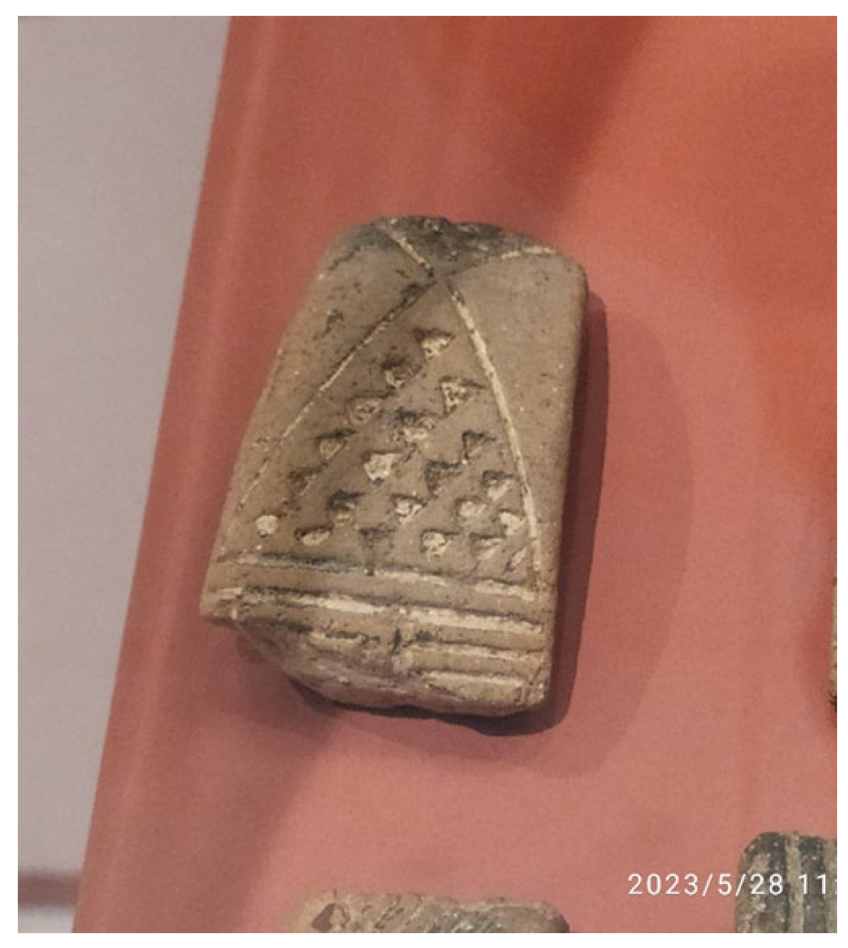
Figure 2.
Alchemical representation of the four basic elements.
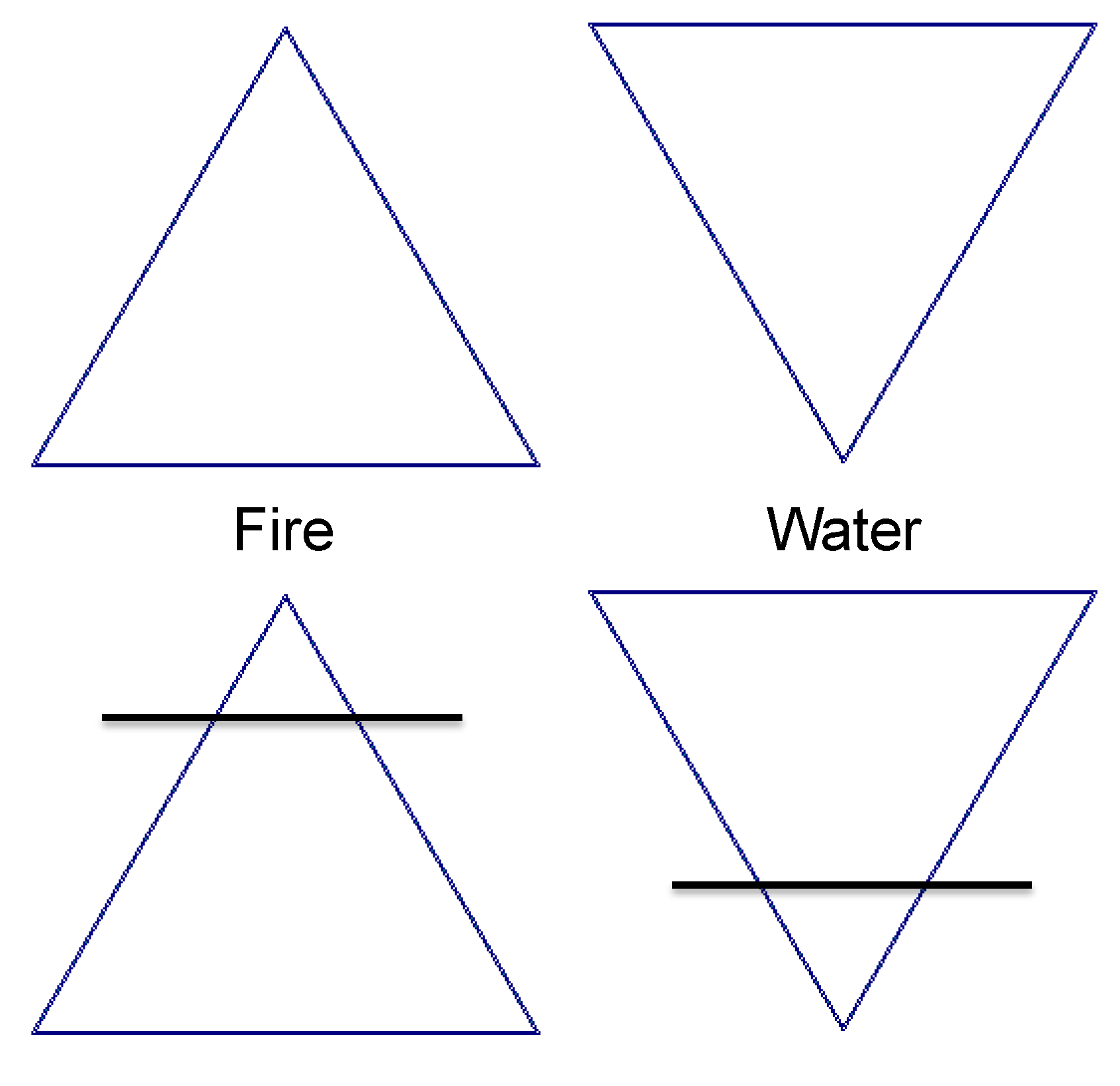
Figure 3.
Platonic solids and their relationships with basic natural elements: cube is the earth, tetrahedron the fire, icosahedron the water, octahedron the air, and dodecahedron the universe. Later, the fifth solid figure was interpreted as the quintessence. Re-elaboration from [28].
Figure 3.
Platonic solids and their relationships with basic natural elements: cube is the earth, tetrahedron the fire, icosahedron the water, octahedron the air, and dodecahedron the universe. Later, the fifth solid figure was interpreted as the quintessence. Re-elaboration from [28].
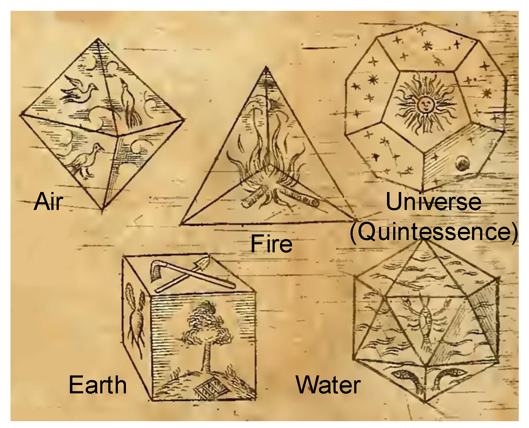
Figure 4.
Construction of a planar polygonal shape using triangles, leading to a circle in the limit conditions.
Figure 4.
Construction of a planar polygonal shape using triangles, leading to a circle in the limit conditions.
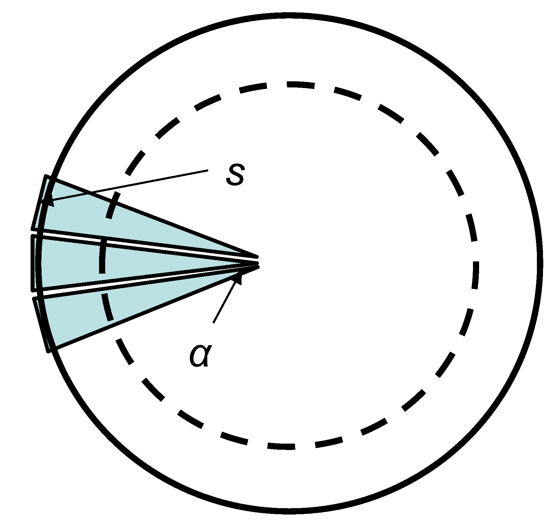
Figure 5.
Roman church of “San Lorenzo fuori le mura” (outside the walls). Two examples of Sierpinski-like floor decoration made by fragments of old imperial material. Medieval age, around 1200 (personal photo).
Figure 5.
Roman church of “San Lorenzo fuori le mura” (outside the walls). Two examples of Sierpinski-like floor decoration made by fragments of old imperial material. Medieval age, around 1200 (personal photo).
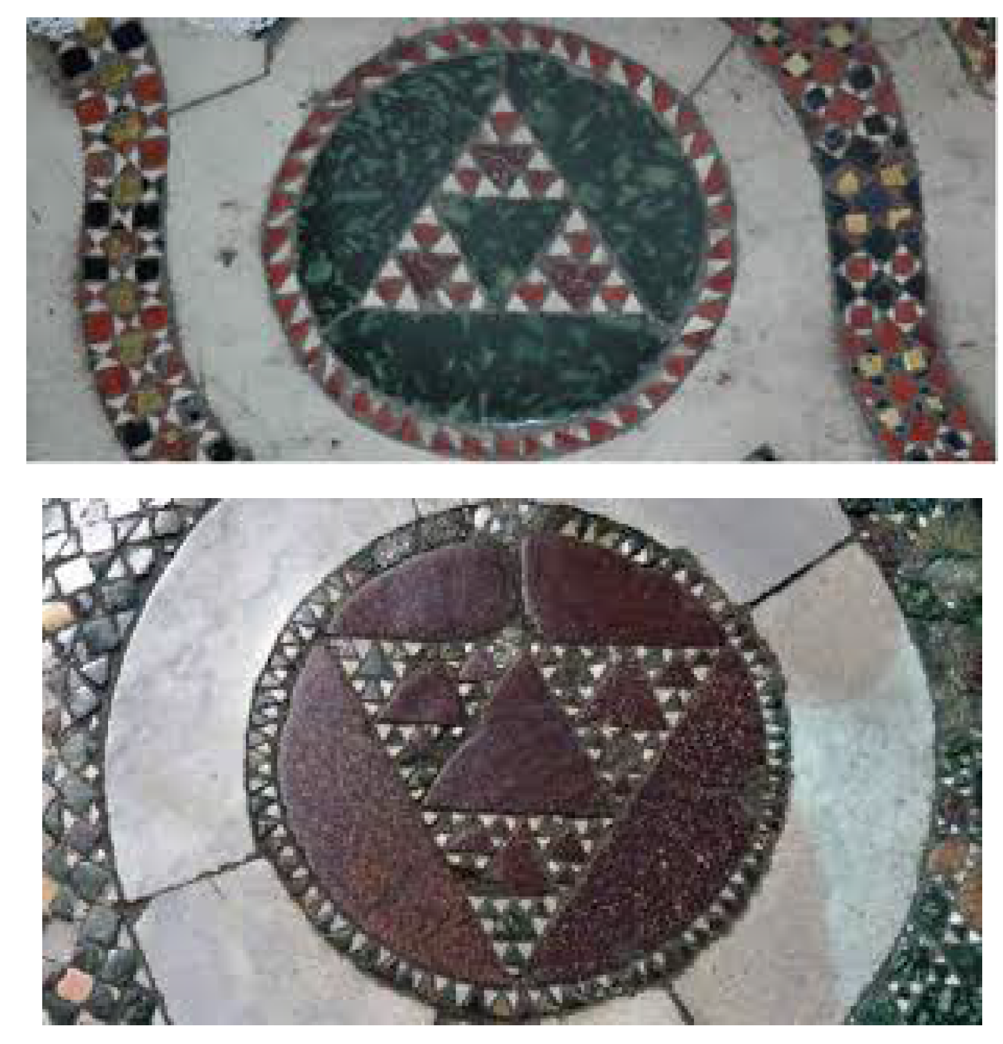
Figure 6.
Triangles used in a Cosmatesque floor: above, from the dome in Civita Castellana, near Roma, (internet photo from https://cosmati.wordpress.com/category/pavimenti-cosmateschi/, by Nicola Severino) and below from the church “Santa Maria in Trastevere” (personal photo).
Figure 6.
Triangles used in a Cosmatesque floor: above, from the dome in Civita Castellana, near Roma, (internet photo from https://cosmati.wordpress.com/category/pavimenti-cosmateschi/, by Nicola Severino) and below from the church “Santa Maria in Trastevere” (personal photo).
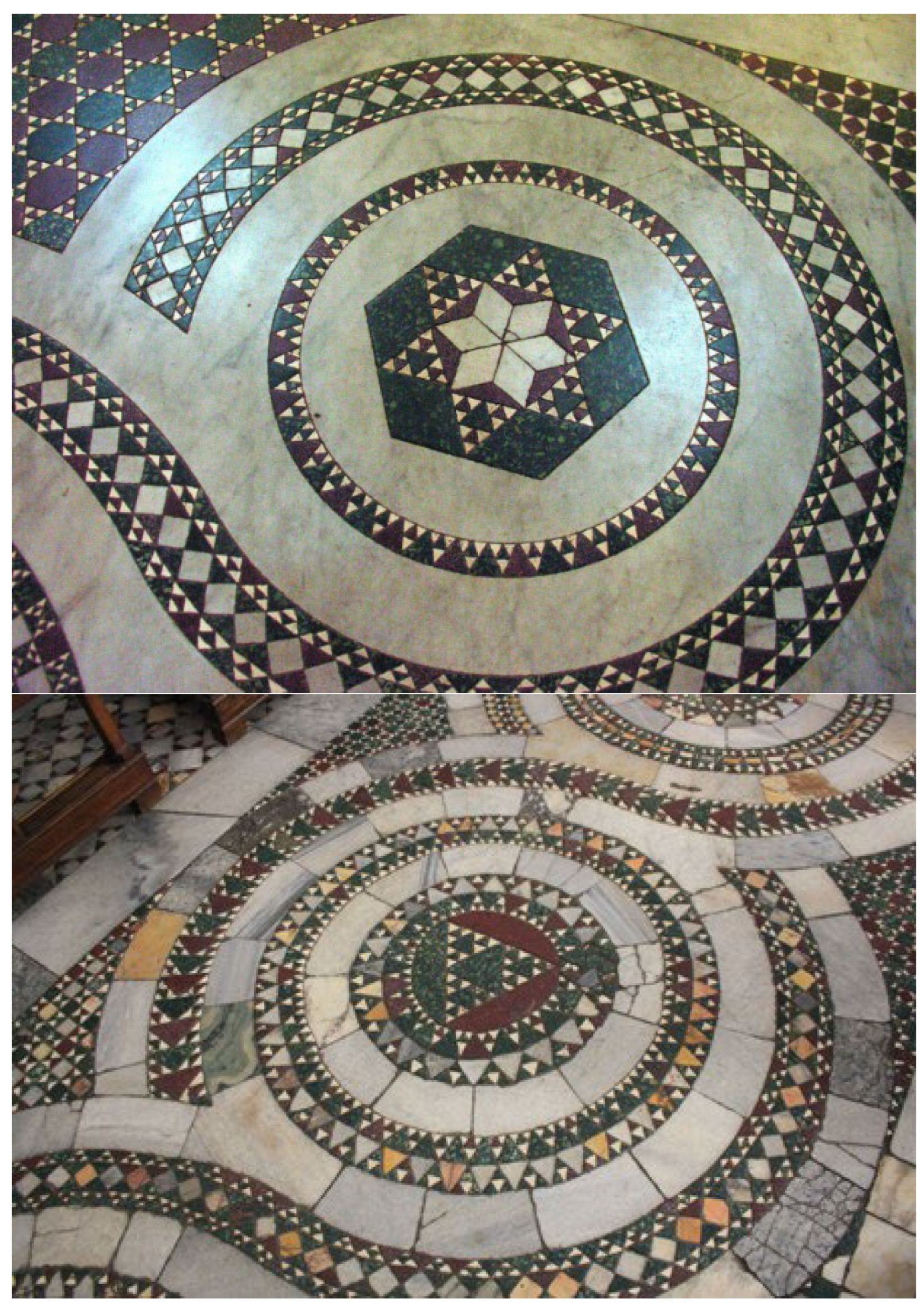
Figure 7.
Labyrinth symbolizing the path towards the truth in the dome of Ravenna, Italy (personal photo).
Figure 7.
Labyrinth symbolizing the path towards the truth in the dome of Ravenna, Italy (personal photo).
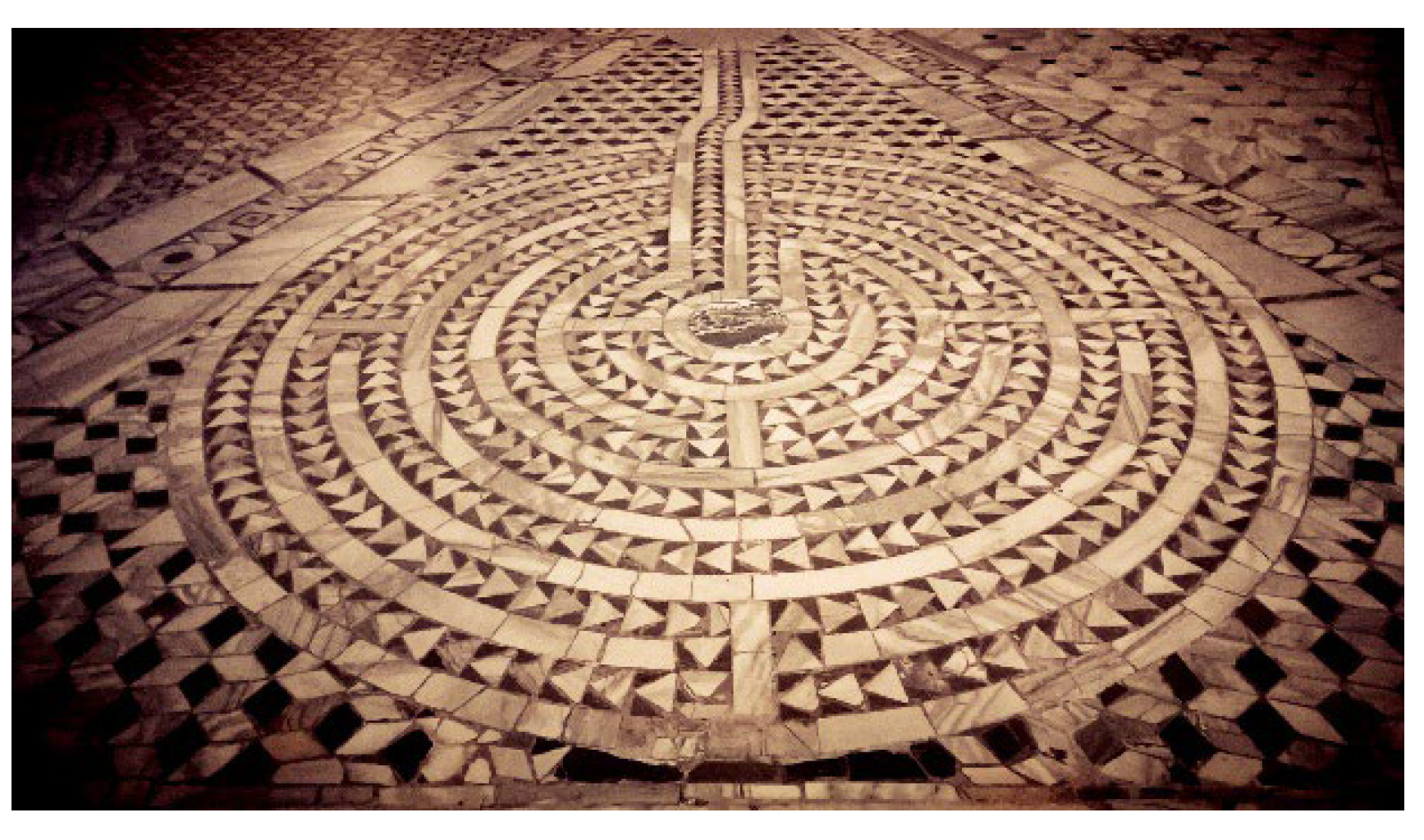
Figure 8.
Cosmatesque style with triangles from the Saint Nilo abbey in Grottaferrata, near Roma. (personal photo).
Figure 8.
Cosmatesque style with triangles from the Saint Nilo abbey in Grottaferrata, near Roma. (personal photo).
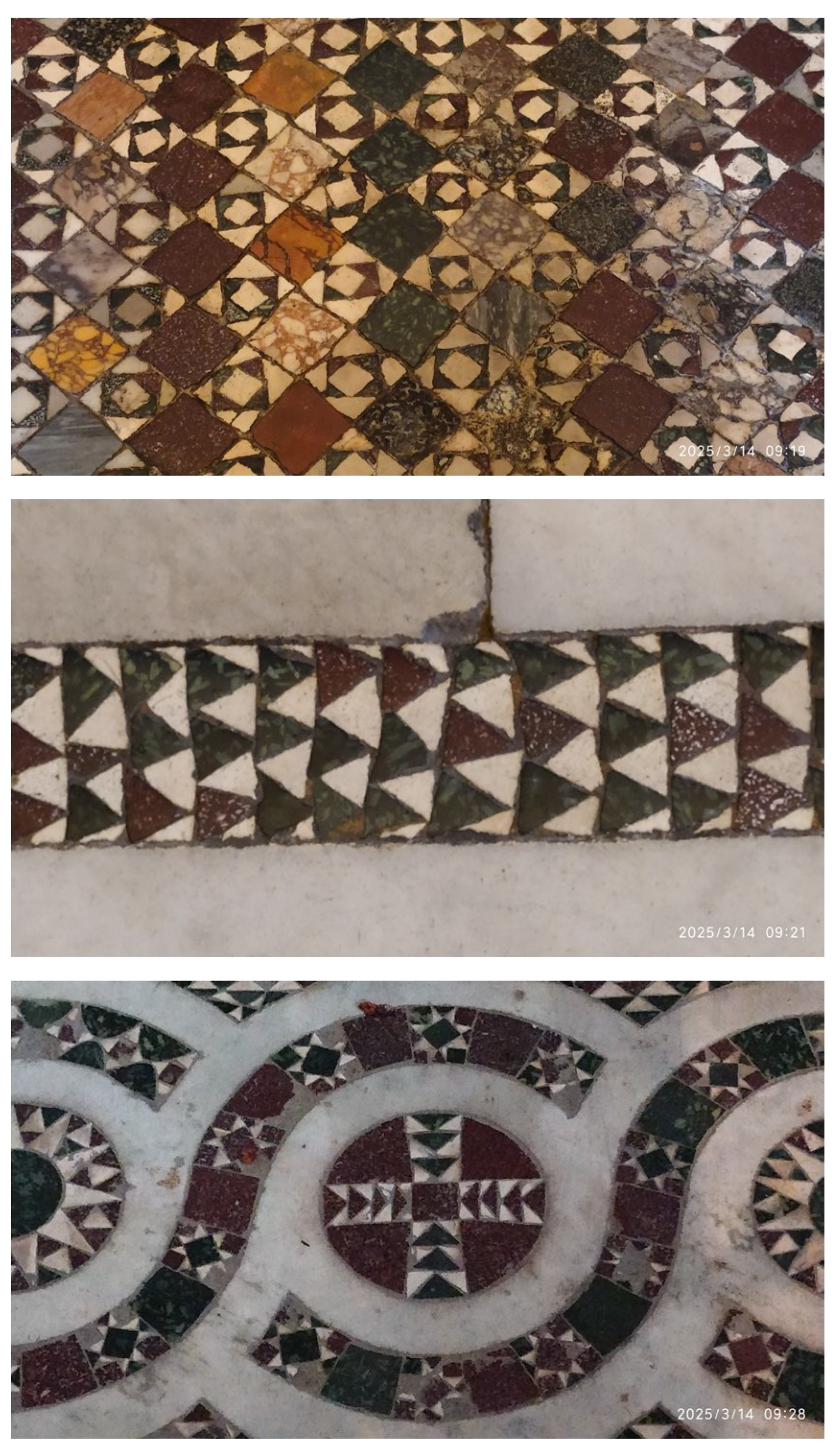
Figure 9.
Iterations to obtain the 3rd level of complexity in the Sierpinski triangle for both positive (top line) and negative (bottom line) shapes.
Figure 9.
Iterations to obtain the 3rd level of complexity in the Sierpinski triangle for both positive (top line) and negative (bottom line) shapes.
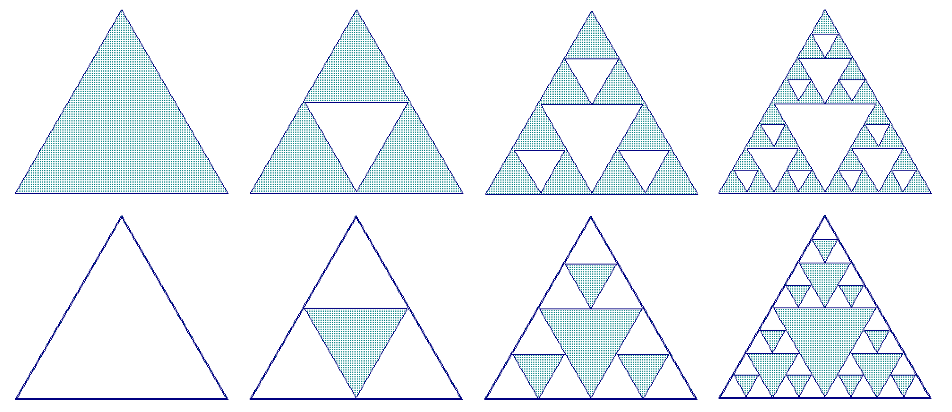
Figure 10.
Configurations and spectrum (in dB) of the Sierpinski bowties. Simulation by Microwave Office 17.1.
Figure 10.
Configurations and spectrum (in dB) of the Sierpinski bowties. Simulation by Microwave Office 17.1.
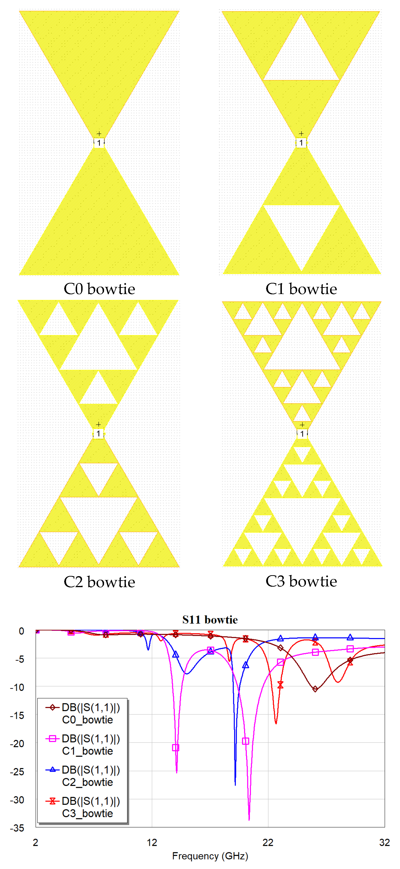
Figure 11.
Front and side view of the radiation pattern for the C0 configuration at 26 GHz.
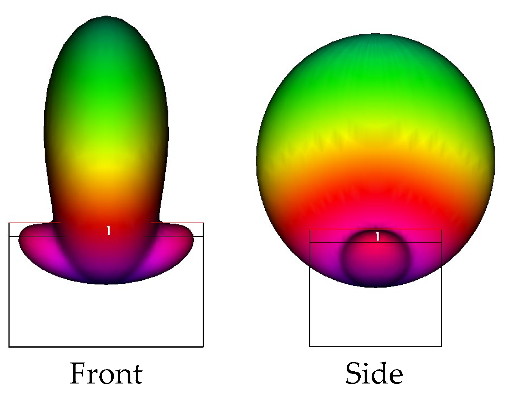
Figure 12.
Front and side view of the radiation pattern for the C1 configuration at 20.3 GHz.
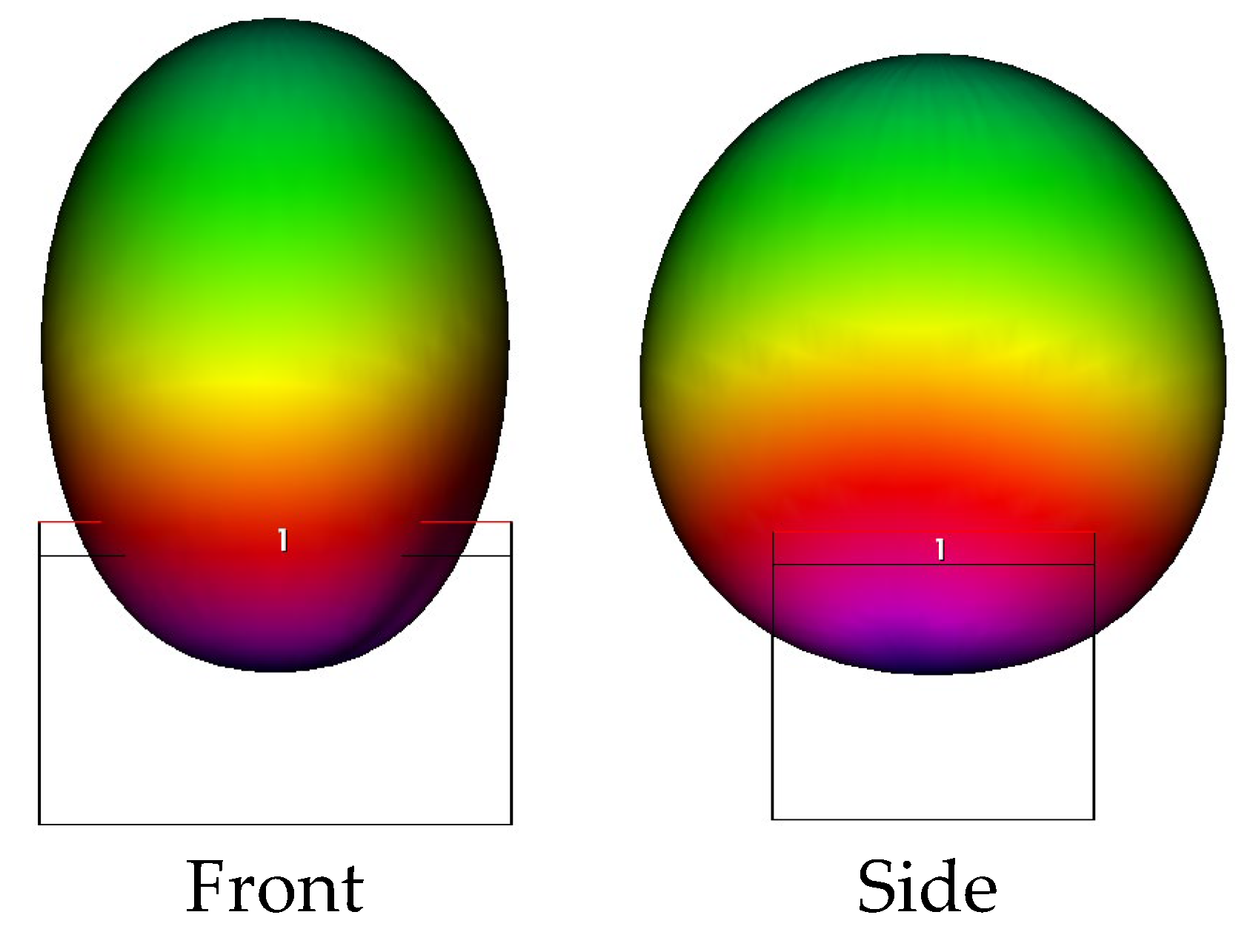
Figure 13.
Four antennas simulated by Microwave Office to study the resonance properties of a structure suitable for immediate GPS applications, including a feeding microstrip line and a metal packaging, with 10 mm separation from the bottom side of a metal box. The edge length is 5.66 cm. The ST. Andrew Cross used to feed the antennas is visible below the radiating elements.
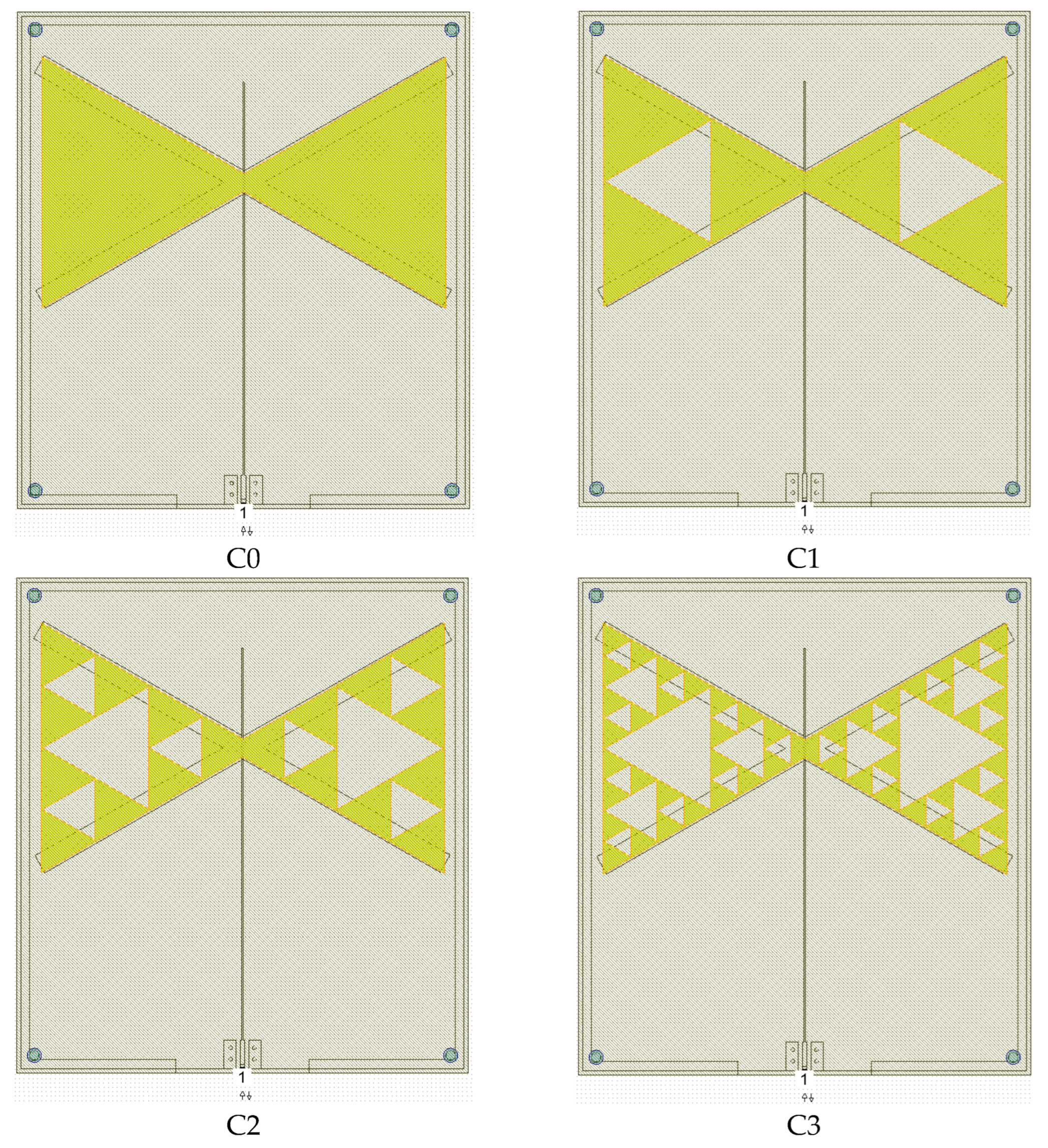
Figure 14.
Resonance response of the simulated antennas, namely four bowties with Sierpinski geometry having internal complexity C0, C1, C2 and C3 respectively.
Figure 14.
Resonance response of the simulated antennas, namely four bowties with Sierpinski geometry having internal complexity C0, C1, C2 and C3 respectively.
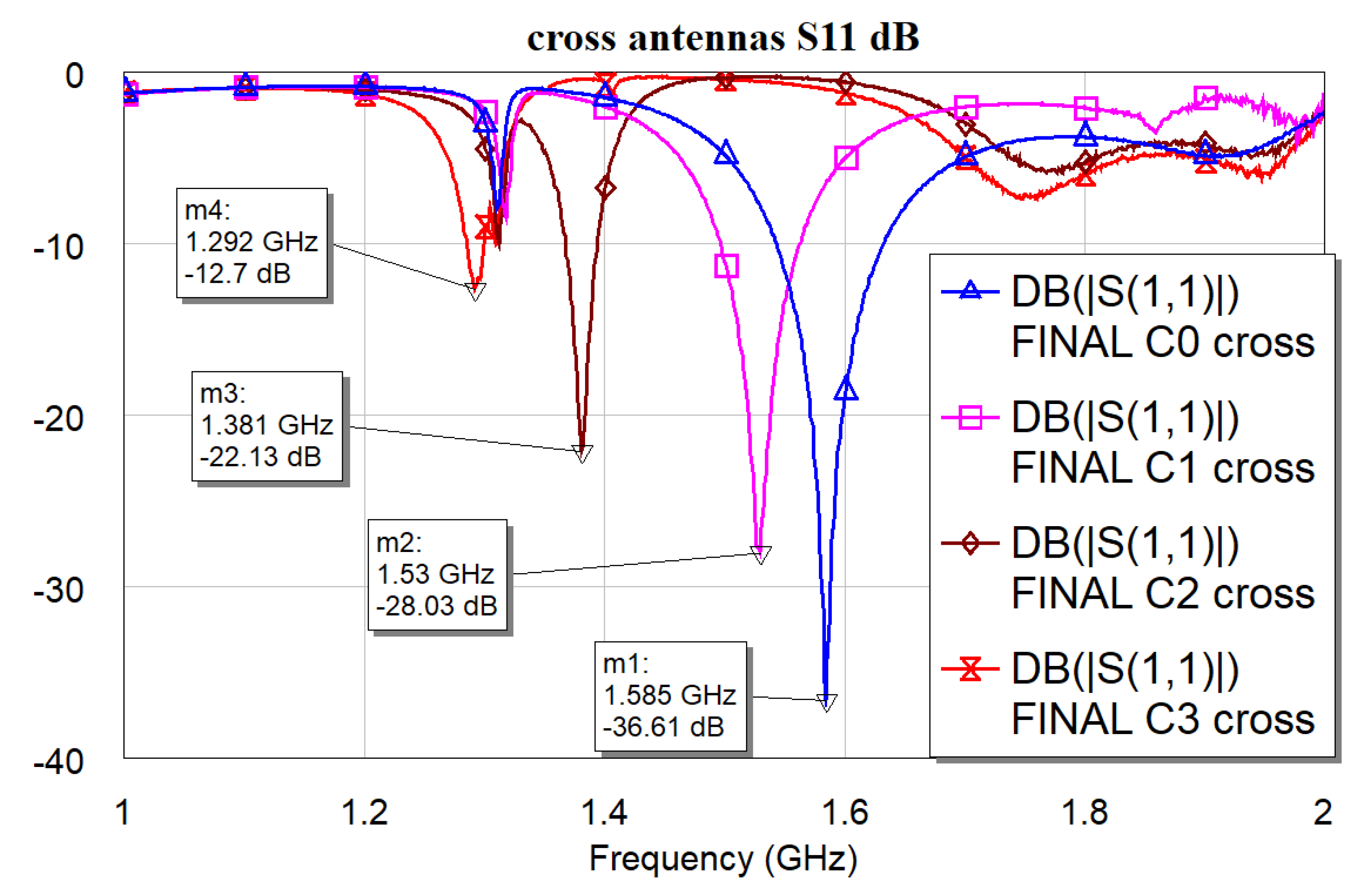
Figure 15.
Simulated resonating structures. Above, the four asymmetric configurations are shown, whereas below, the four symmetric ones are seen. The blue line is the feeding microstrip, 50 μm far from the triangle edge. Metallization is always 5 μm.
Figure 15.
Simulated resonating structures. Above, the four asymmetric configurations are shown, whereas below, the four symmetric ones are seen. The blue line is the feeding microstrip, 50 μm far from the triangle edge. Metallization is always 5 μm.
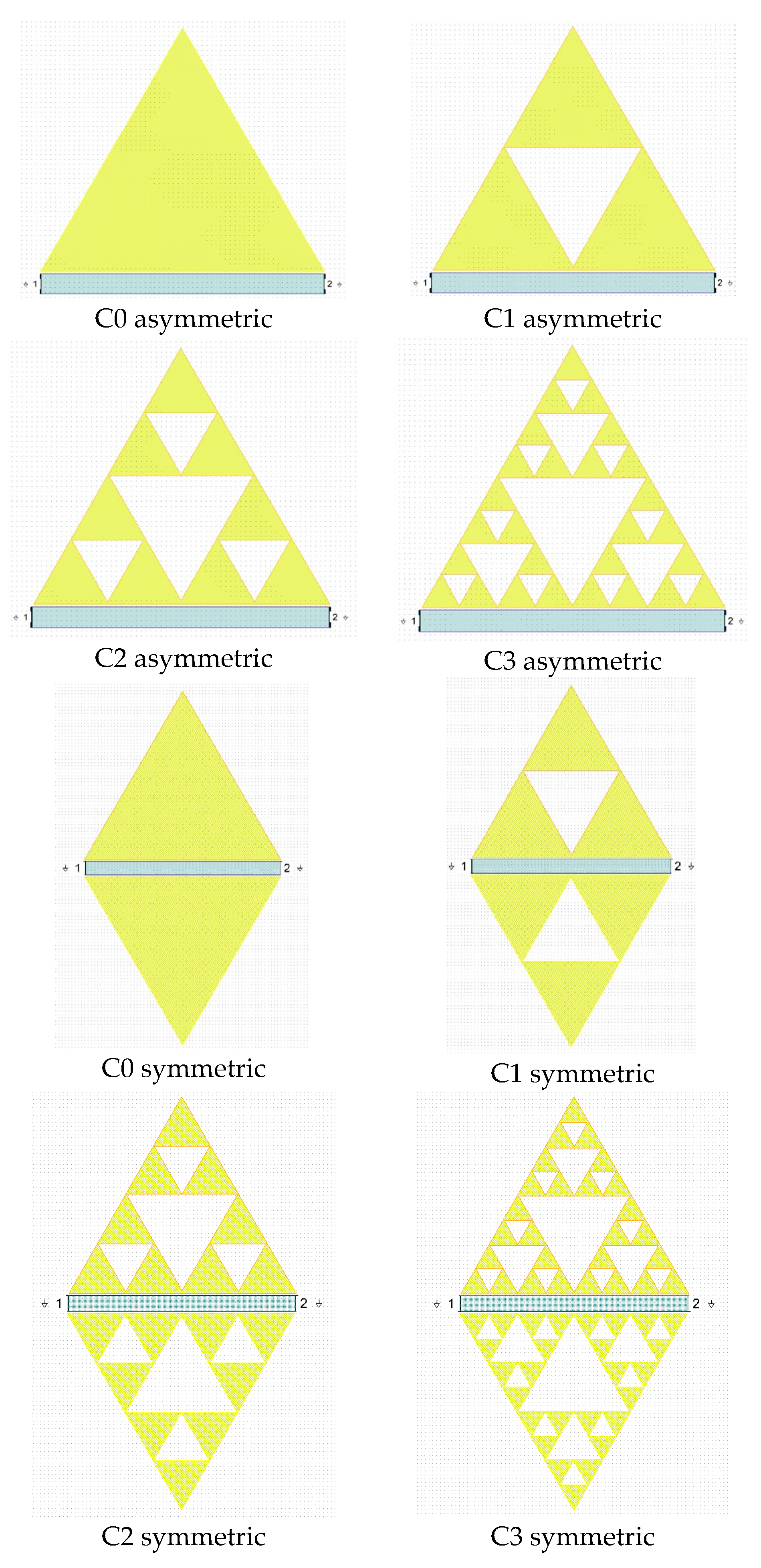
Figure 16.
Simulated response of the S21 trasmission parameter (in dB) for the asymmetric and symmetric resonators. Modes excited up to the X-Band (12 GHz) are shown in both cases. Simulation by Microwave Office 17.1.
Figure 16.
Simulated response of the S21 trasmission parameter (in dB) for the asymmetric and symmetric resonators. Modes excited up to the X-Band (12 GHz) are shown in both cases. Simulation by Microwave Office 17.1.
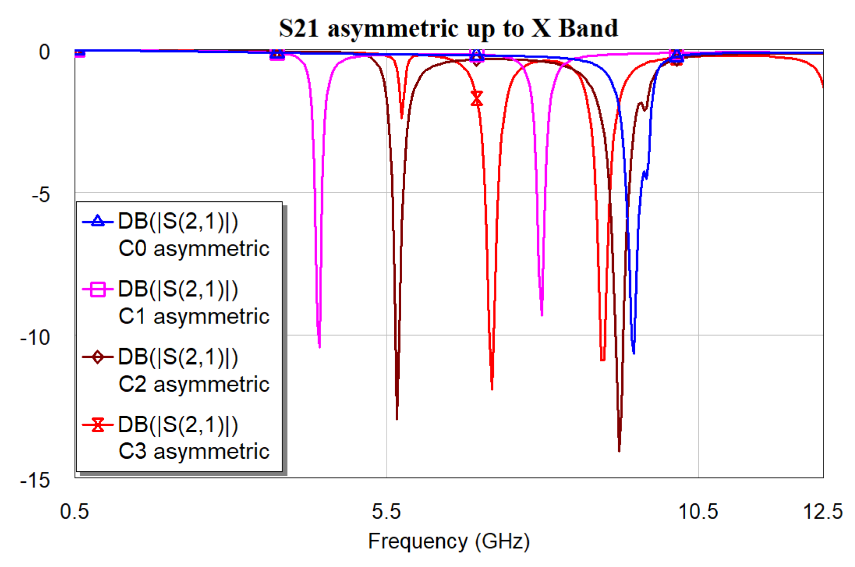
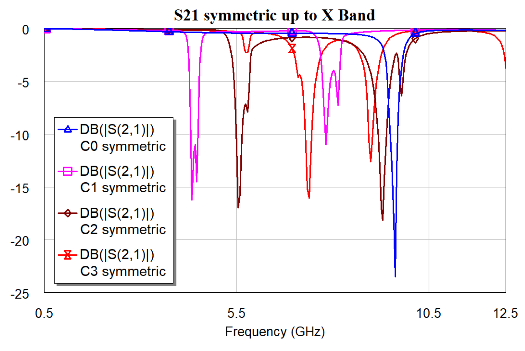
Figure 17.
Simulated spectral response for the S21 parameter (in dB) of the C3 resonator in the symmetric configuration up to 32 GHz.
Figure 17.
Simulated spectral response for the S21 parameter (in dB) of the C3 resonator in the symmetric configuration up to 32 GHz.
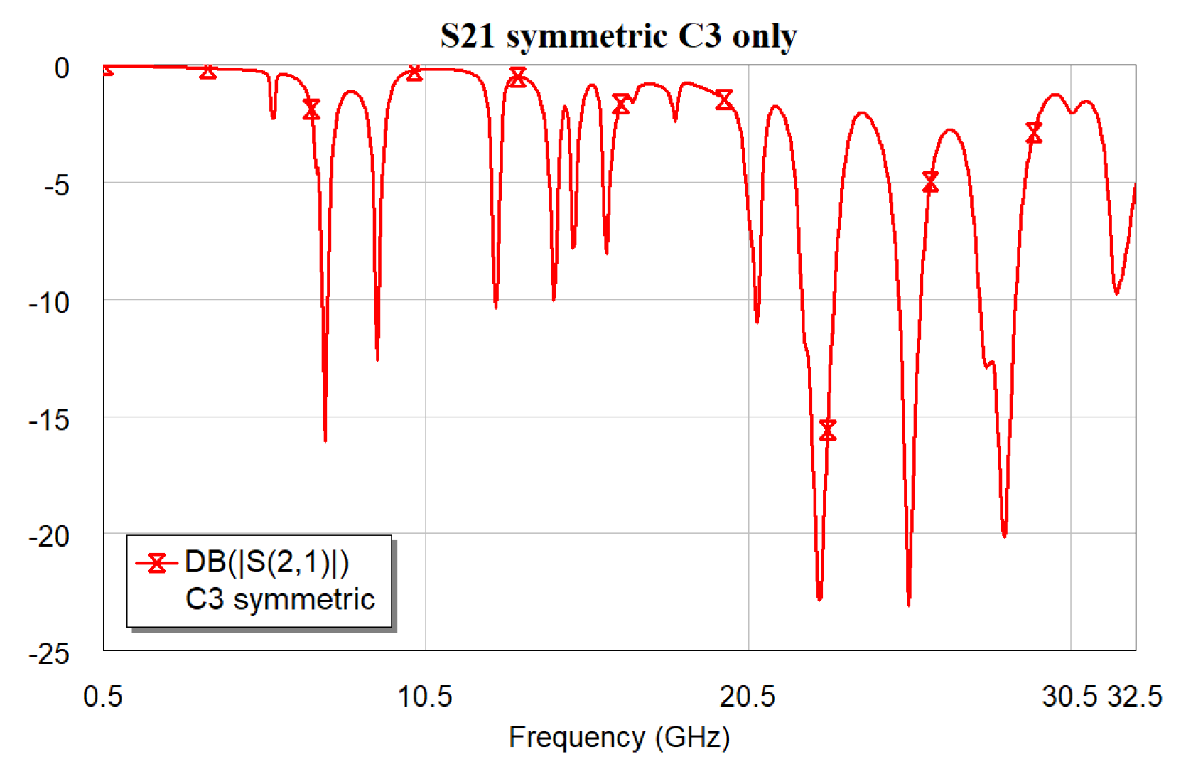

Table 1.
Frequency of resonance for the simulated structures (asymmetric and symmetric).
| Resonator | Resonance frequencies [GHz] | ||
|---|---|---|---|
| Fres1 | Fres2 | Difference | |
| C0 asym | 9.46 | --- | --- |
| C1 asym | 4.42 | 7.98 | 3.56 |
| C2 asym | 5.66 | 9.22 | 3.56 |
| C3 asym | 7.18 | 8.94 | 1.76 |
| C0 sym | 9.62 | --- | --- |
| C1 sym | 4.34 | 7.82 | 3.48 |
| C2 sym | 5.54 | 9.30 | 3.76 |
| C3 sym | 7.38 | 8.98 | 1.60 |
Disclaimer/Publisher’s Note: The statements, opinions and data contained in all publications are solely those of the individual author(s) and contributor(s) and not of MDPI and/or the editor(s). MDPI and/or the editor(s) disclaim responsibility for any injury to people or property resulting from any ideas, methods, instructions or products referred to in the content. |
© 2025 by the author. Licensee MDPI, Basel, Switzerland. This article is an open access article distributed under the terms and conditions of the Creative Commons Attribution (CC BY) license (http://creativecommons.org/licenses/by/4.0/).
Copyright: This open access article is published under a Creative Commons CC BY 4.0 license, which permit the free download, distribution, and reuse, provided that the author and preprint are cited in any reuse.


