
Submitted:
09 April 2025
Posted:
10 April 2025
You are already at the latest version
Abstract
Hydrogen fuel cell vehicles are one of the most promising alternatives to achieve transport decarbonization targets thanks to their moderately high efficiency and low refueling time combined with zero exhaust emissions operation. In order to reach reasonable power density figures, fuel cell systems are generally supercharged by radial compressors, which can encounter significant limitations associated to surge and choke operation especially in high altitude. Alternatively, the current paper explores the altitude operation of a fuel cell system combined with a roots compressor. First, the balance of plant model is build in Simscape platform combining a physical and chemical 1D fuel cell model for the stack, calibrated against literature data at different pressure and temperature values, and the characteristic maps of the roots compressor. Then, the model is used to explore the balance of plant operation in a working range between 10 and 200 kW and an altitude range between sea level and 5 km. The results show that the compressor is capable to operate around the highest efficiency area (between 60 and 70%) for a wide range of altitude and power conditions, limiting the negative impact of the altitude in the system efficiency up to 3%. However, once the compressor efficiency falls below 60% the balance of plant performance rapidly drops, overcoming the benefits of the working pressure on the fuel cell stack operation and limiting the peak net power produced.
Keywords:
Proton exchange membrane fuel cell (PEMFC)
; Altitude
; Compressor
; Efficiency
1. Introduction
Hydrogen fuel cell vehicles (FCVs) are emerging as a promising solution for reducing greenhouse gas emissions and addressing climate change as an alternative to traditional gasoline and diesel fueled vehicles [1]. As Earth's temperature has already risen by about 1°C and may reach 1.5°C if current trends continue, the need for decarbonization has become increasingly urgent [2]. The transition to zero-emission technologies across various sectors is vital for limiting global warming [3]. This includes road, air, and maritime transport, with road vehicles alone accounting for approximately 77% of transportation-related CO2 emissions in 2020 [4]. Additionally, vehicles powered by internal combustion engines can produce other emissions such as nitrogen oxides, particulate matter or incomplete combustion products. While exhaust aftertreatment systems can largely mitigate these species, their cost and complexity are increasingly large to achieve current regulatory requirements.
In this sense, fuel cells offer a promising alternative, since they can produce electrical energy by an electrochemical reaction producing no direct harmful emissions [5]. Among various fuel cell types, proton exchange membrane fuel cells (PEMFC) are one of the most widely used, particularly in applications such as transportation and stationary power generation [6]. PEMFC are favored for their high efficiency, low operating temperature and scalability, making them suitable for a wide range of applications [7]. The key reaction in a PEMFC occurs between hydrogen, which is supplied to the anode, and oxygen, supplied to the cathode generally using environmental air as a source [8]. The air supply needs to be accurately controlled to ensure that the oxygen content is enough for the electrochemical reaction to proceed efficiently [9,10]. For this purpose, fuel cell systems rely on air compressors, normally electrically driven, which pressurize and supply air to the cathode in order to increase the fuel cell power density [11]. The compressor must deliver sufficient air mass flow to maintain a proper stoichiometric ratio between the fuel (hydrogen) and oxygen, typically managed by adjusting the air-to-fuel ratio [12,13], avoiding local oxygen starvation that can promote the degradation of the fuel cell. However, compressors also consume a portion of the system's power, making their efficiency and power consumption key considerations in overall fuel cell system performance[14,15].
Previous studies have explored the role of the compressor in fuel cell systems for passenger car applications. Dongdong et al. [16] studied a high-speed centrifugal compressor model for PEM fuel cells, designed for automotive applications. A feedforward controller managed air mass flow, mitigating disturbances during dynamic load changes. This compressor maintained optimal oxygen levels, enhancing fuel cell efficiency and preventing oxygen starvation. It demonstrated efficient performance under varying load conditions. Shuhao et al. [17] designed a magnetically levitated centrifugal compressor with forward-curved blades for automotive PEMFCs, achieving a pressure ratio of 1.10 and an isentropic efficiency of about 50%. Their approach integrated numerical simulations, experimental validation, and a novel algorithm to optimize blade profiles. This design addressed low flow rate challenges and emphasized stable operation, enhancing efficiency in PEMFC systems. Nabeel et al. [18] studied a numerical model for a two-stage turbo-compressor in a fuel cell system, achieving a pressure of 4.2 bar and a 70.8% efficiency. It highlighted the importance of temperature control and power management for optimal performance. The model allowed for adjustments to input parameters, enhancing its applicability in real-world scenarios. Junbo et al. [19] conducted a comprehensive study on fuel cell compressors used in automotive applications, focusing on types like roots, screw, centrifugal, and turbochargers. They discussed control strategies such as PID, fuzzy logic, and hybrid methods to manage the air supply. Key components like compressors and bypass valves played a vital role in optimizing fuel cell performance and durability. The mechanical and gas flow responses of compressors were also examined, emphasizing the need for precise control during operation.
One of the aspects that can significantly affect both compressor and fuel cell performance is the altitude [20,21]. At higher altitudes, the atmospheric pressure decreases, which results in reduced air density [22]. If the fuel cell is not supercharged, this would imply a proportional decrease in the fuel cell performance. However, in supercharged systems the compressor can partially compensate the lower environmental pressure by operating at higher pressure ratios, thus increasing its electrical power consumption and raising concerns about its durability and performance during prolonged use [23]. Additionally, especially at very low or very high mass flows (related to low and high power demand from the fuel cell) surge and choke limitations can prevent the compressor from reaching such high pressure ratio values depending on the particular compressor technology and design.
Few studies in the literature have studied the effects of altitude in performance of PEM fuel cell. Pratt et al. [23] examined the performance of an air-breathing (atmospheric) proton exchange membrane (PEM) fuel cell at high altitudes. They demonstrated that reduced pressure negatively affects performance primarily due to activation losses, while airflow played a secondary role. Increasing airflow improved performance, particularly at low pressures, highlighting the importance of optimizing air supply for aviation applications. These findings are crucial for designing fuel cells that are effective at high altitudes. Hordé et al. [20] explored the performance of PEMFCs in aviation and identified notable efficiency losses at higher altitudes due to decreased ambient pressure and lower oxygen levels. They suggested that increasing the air stoichiometric factor can help mitigate this decline. Lapeña-Rey et al. [25] discussed a fuel cell-powered UAV designed for low-altitude surveillance, which could achieve flight times of nearly four hours. It employed a lightweight PEM fuel cell combined with a hydrogen generator. However, the UAV operated at an altitude of 1,000 meters above ground level, which is lower than the typical surveillance altitudes of around 5,000 meters. This difference required certain design adaptations to accommodate the effects of lower atmospheric pressure and temperature.
1.1. Knowledge Gaps
Despite advancements performed in understanding fuel cell systems operation during the years, including the altitude impact, most of these studies have been performed using radial compressors. This technology can be particularly affected by the operation in altitude due to surge and choke limitations, together with a high sensitivity of efficiency to the specific working point. Instead, other technologies such as screw or roots compressors, also in scope for future development of hydrogen fuel cell systems [26], may offer a more robust operation in a wider range of altitude conditions without a so severe impact on rated power operation and fuel consumption. However, the information available in the literature about the matching of such compressor technology with PEMFC systems is scarce, and the interaction with altitude operation is still to be explored.
1.2. Contribution and Objectives
The main objective of this paper is to investigate and analyze the impact of altitude on a roots compressor operation within a heavy-duty PEM fuel cell system. For this purpose, a balance of plant evaluation will be made coupling a previously existing physical and chemical model of a PEM fuel cell [27] and detailed operating maps of the target roots compressor [26]. Achieving this goal, the following specific objectives will be accomplished:
- Understand the matching between a roots compressor characteristic map and a fuel cell sized for a heavy-duty truck application
- Evaluate the effect of the compressor operating conditions (pressure ratio and efficiency) on the compressor power consumption and balance of plant efficiency.
- Quantify the implications of altitude in the maximum achievable power and energy balance.
- Discuss the relationship between the compressor map and the altitude impact.
2. Materials and Methods
In this section, the main aspects of the methodology followed during the simulations will be detailed. First, the fuel cell balance of plant model will be described, including the validation of the physical model used to simulate the stack response as a function of the cathode working pressure. Then, the characteristics and working map of the roots compressor technology under investigation will be presented. Finally, the test matrix including altitude variations will be summarized.
2.1. Balance of Plant Model
The current work explores the altitude effects on compressor and fuel cell performance for a heavy-duty vehicle. For this purpose, the balance of plant proposed sketch in Figure 1 is modeled using Matlab Simscape platform. In the anode side, the hydrogen from the fuel tank goes through a controlled valve that is used to set the operational pressure at the fuel cell inlet pin,a, and afterwards to a heat exchanger to control the temperature Tin,a, particularly during the warm-up phase. After this heat exchanger, the flow coming from the fuel tank is mixed with the hydrogen excess flow recirculated from the anode exhaust by means of a recirculation pump (P). Finally, a membrane humidifier is used to set the final humidity content of the anode stream. In the cathode side, the first element in the line is an air filter, necessary to ensure that no impurities arrive at the cathode gas channels, and characterized by a 2% pressure drop at the maximum mass flow conditions. Afterwards, an electrically driven compressor is used to control the mass flow and pressure of the air arriving at the fuel cell (pin,c), which a second heat exchanger used to control the inlet temperature Tin,c. Finally, a second membrane humidifier sets the humidity level of the cathode gas stream, using as a water source the one recuperated from the cathode exhaust. It has to be considered that, additionally to these elements, a real system would also include two additional elements that are not considered in the current simulations. First, a thermal management system is used to maintain the PEMFC stack at the optimal working temperature (around 70ºC) once the system warm-up phase is completed. Second, a hydrogen purge circuit derives the hydrogen from the recirculation line to the cathode exhaust when the hydrogen purity reaches a certain minimum value due to nitrogen crossover across the stack. However, in the current work these systems are not considered since they have no direct relation with the system performance in altitude conditions, which is the main scope of the activity.
One of the key elements in this model, together with the electrical compressor (which will be described in the next subsection) is the fuel cell stack itself. Given the nature of the study, it is critical that the selected submodel for the fuel cell stack provides physical sensitivity to the working pressure in anode and cathode, which has a direct impact on both activation and mass transfer losses. In the current work, the open source model developed by Vetter et al. [27] is selected. This model has been calibrated using experimental data from the literature [28,29] including different temperature and pressure conditions, up to a maximum pressure of 2.5 bar. Figure 2 shows the comparison between experimental and simulated polarization curves for three of the conditions extracted from the previous studies. As it can be seen, the model is well capable to reproduce the fuel cell performance in the whole current density range.
Once the fuel cell electrochemical response is validated at the cell level, its operation is scaled up to be representative of a PEMFC based powertrain system in a heavy-duty vehicle [30] . Particularly, a total of 1000 cells with an active area of 280 cm2 each are considered in order to provide a maximum fuel cell power of 225 kW. Table 1 presents this information together with the most important physical and chemical parameters obtained during the fuel cell model calibration process.
2.2. Roots Compressor
As previously introduced, a roots compressor technology [26] is selected to supercharge the fuel cell stack. Figure 3 summarizes the characteristic maps of the screw compressor used for the current study in terms of isentropic efficiency (A) and compressor corrected speed (B) as a function of corrected mass flow and pressure ratio. As can be seen, in this kind of compressor technology the speed controls mainly the air mass flow provided, since the constant speed lines are practically vertical. Instead, at a given compressor speed there is a wide variation of the pressure ratio, with a maximum value around 2.8 achieved up to a corrected mass flow of 0.35 kg/s (corresponding to ~15000 rpm), point from which the maximum pressure ratio achievable starts going down. Finally, it can be also noted that the peak isentropic efficiency reaches 70%, achieved in a wide area ranging 0.15-0.35 kg/s and 1.4-2.1 pressure ratio. From that point, the main efficiency deterioration is produced when the corrected mass flow reduces below 0.05 kg/s.
2.3. Simulation Conditions
Throughout the simulations, the following conditions have been maintained:
- Ambient temperature and pressure conditions are calculated as a function of altitude according to the international standard atmosphere, in a range between sea level (0 km) and 5 km.
- The air filter is assumed to produce a maximum pressure drop of 2% for the highest operational air mass flow (0.3 kg/s). For lower air mass flows, a linear decay of this pressure drop is assumed.
- The compressor reduced speed is controlled to achieve the target air mass flow for a constant oxygen excess ratio of 2.
- The compressor electrical power is adjusted to control its pressure ratio, in a range between 1.05 and 2.8, with a step size of 0.025. The inlet pressure at the fuel cell is assumed equal as the compressor outlet pressure for both cathode and anode streams.
- The temperature of cathode and anode gas streams, as well as the internal fuel cell stack temperature, is set at 73ºC in order to reach the maximum proton conductivity of the membrane.
- Relative humidity at both cathode and anode gas streams is set at 70%.
- The hydrogen excess ratio defined at the anode inlet is set at 1.5, with the hydrogen excess being used to calculate the power consumption from the recirculation pump.
- The voltage in the fuel cell stack is limited to a minimum value of 0.6 V/cell in order to operate in the range covered during the validation phase and ensure that the stack does not reach oxygen-limited operation that could eventually lead to its degradation in real conditions.
3. Results
In this section, the main results from the simulations are presented and discussed. The analysis is divided into two parts: first, a detailed evaluation of the balance of plant operation and stack-compressor matching is performed at sea level conditions; later, the impact of the altitude is evaluated for a net power range between 20 and 200 kW (or the maximum achievable).
3.1. Sea Level Analysis
Figure 4 shows the information about the fuel cell stack and compressor operation as a function of the pressure ratio at sea level. For this purpose, 6 levels of pressure ratio (between 1.05 and 2.8, in steps of 0.35) are depicted. Figure 4A) shows the evolution of the power produced by the fuel cell stack against the current density (for different pressure levels. At low current densities, it can be seen that the impact of the pressure ratio is relatively small, despite higher pressure at the fuel cell stack is always positive for the fuel cell performance alone. As the current density increases, the effect of the operational pressure is more evident both in terms of the power produced and the range of current density, which reaches a maximum value of 1.6 A/cm2 for the last two pressure ratio cases. Additionally, it can be seen that for these two values the peak power is actually produced at a slightly lower current density (~1.6 A/cm2), beyond which mass transport losses ramp up producing a decrease of the electrical power despite the increase in the current. Figure 4B) provides the counter figure in terms of the compressor power consumption as a function of the air mass flow. At low values of air mass flow (proportional to the fuel cell current) the compressor power is practically constant due to the fact that the increase of air mass flow is compensated by the continuous increase also of the compressor efficiency, as depicted in Figure 4C. This effect is more clear as the pressure ratio on the compressor increases. Once the efficiency becomes more stable, the compressor power consumption shows an almost linear evolution, dominated by the air mass flow variation. It can also be seen that the sweet spot for the compressor operation appears for pressure ratios between 1.4 and 1.75, which a peak efficiency near 70%, as already discussed when introducing the compressor map in Figure 3.
Figure 5 shows the evolution of the balance of plant efficiency as a function of the produced net power, which can be seen as the net balance of the aforementioned stack and compressor terms, since the recirculation pump contribution is independent from the pressure ratio selected. In general, the results show that the best efficiency is achieved when using the minimum possible pressure ratio for a given produced net power, due to the significant impact of the compressor consumption on the overall energy balance. However, as the net power demand increases the best efficiency is found for higher pressure ratios until reaching the pr=2.45 condition. Afterwards, further increases of the pressure do not affect significantly the fuel cell stack but translate into a higher compressor consumption, damaging the balance of plant efficiency.
3.2. Altitude Impact
Figure 6 analyzes the system level performance as a function of the altitude level. Figure 6A) shows the optimal pressure ratio for each altitude as a function of the balance of plant net power. Until approximately 100 kW it can be seen that the optimal pressure ratio is approximately constant, with very little variation also in terms of the altitude condition. From that point, the optimal pressure ratio increases rapidly when increasing the net power demand, more aggressively as the altitude also increases in order to compensate the lower environmental pressure. For the most demanding conditions, the compressor can take up to 18% of the total electrical power produced by the fuel cell (Figure 6B). Looking at the extension of the data in the x-axis, it is also noticeable that the maximum power deteriorates also with the altitude, with a maximum value of 135 kW (vs. the nominal 200 kW, a 32.5% deterioration) for the highest altitude of 5km. Finally, Figure 6C) provides the information of the balance of plant efficiency, where a deterioration between 3 and 7% can be observed when increasing the altitude at constant net power demand. This deterioration is more severe as the system approaches the rated power condition.
Figure 7 analyzes in further details the operation of the compressor in terms of the pressure ratio (Figure 7A) and efficiency (Figure 7B) evolutions against the corrected mass flow. As it can be seen, the reduction of the ambient pressure as a function of the altitude tends to increase the corrected mass flow values, whose maximum moves from around 0.25 kg/s at sea level conditions to 0.35 kg/s in the most extreme conditions. However, thanks to the characteristics of the roots compressor selected for this study, these conditions still fall into the high efficiency region of the compressor map, allowing to maintain efficiencies between 60 and 70% throughout the majority of the operating range even at 5 km altitude. This result confirms the suitability of this compressor technology to minimize the negative impact of altitude on the working range and efficiency of fuel cell powered vehicles compared to other boosting systems available. However, it has to be noted that for the highest altitude of 5 km, the highest working point is limited to a corrected mass flow of 0.3 kg/s and a pressure ratio of 1.8, which is well inside the compressor map. Therefore, the net power is not limited by the extension of the compressor map itself, but by the fact that after this point the compressor efficiency starts deteriorating again. Thus, the expected increase of the fuel cell stack power induced by the higher pressure and air mass flow is overcome by the higher also compressor power consumption coming from the lower efficiency operation.
Finally, Figure 8 shows the information about the fuel cell stack operating conditions as a function of altitude. Figure 8A) depicts the actual pressure achieved in the cathode inlet stream. There is a clear decreasing trend of the working pressure with the altitude in the low-to-mid net power conditions. On the contrary, once the net power exceeds 135 kW, the optimal balance of plant operation is found for nearly identical levels of pressure in the cathode regardless the working altitude. This is related to the fact that in these conditions is where the pressure has the highest impact on the fuel cell stack performance, as can also be observed in Figure 8B). This, together with the relatively low variability of the compressor efficiency once the corrected mass flow exceeds 0.15 kg/s, makes the system optimization swing towards the fuel cell stack sweet spot.
4. Conclusions
In the current paper, an investigation of the altitude effects on the operation of a supercharged heavy-duty fuel cell powerplant equipped with a roots compressor is performed. For this purpose, the complete balance of plant model is developed in Simscape platform. For the fuel cell stack, a 1-dimensional physical and chemical model extracted from the literature is calibrated against experimental data at different temperatures and pressures at the single-cell polarization curve level. Then, the number of cells and effective area are scaled up to provide a maximum net power of 200 kW, representative of the requirements from a heavy-duty vehicle. The roots compressor, characterized by a maximum pressure ratio of 2.85 and maximum corrected flow of 0.5 kg/s, is calculated using the information from the efficiency and corrected speed maps. The model is completed by including and air filter, characterized with a pressure drop up to 2% for the maximum mass flow conditions, the anode recirculation system, membrane humidifiers for both anode and cathode streams and a simplified thermal management system aimed at maintaining a constant temperature of 73ºC, where the maximum proton conductivity is found. The model is explored in an altitude range between sea level and 5 km, optimizing the compressor and fuel cell stack working points to achieve the highest balance of plant efficiency for a net power range between 10 and 200 kW (or the maximum achievable at a given altitude). With this methodology, the following conclusions can be extracted:
- The pressure in the fuel cell stack helps to extend the current density operating range and therefore increase the achievable fuel cell power. However, the sensitivity to the pressure starts reducing when the pressure exceeds 2 bar, which minimum differences achieved from 2.45 bar on.
- At sea level operation, a minimum compressor power consumption is seen at low-to-mid fuel cell power (i.e. air mass flow) operation, dominated by the isentropic efficiency evolution. This minimum power increases nearly exponentially with the pressure ratio.
- At mid-to-high power conditions, the roots compressor efficiency is nearly constant and close to the highest efficiency, and the compressor power consumption is dominated by the air mass flow.
- As altitude increases, the maximum corrected air mass flow tends to increase as a consequence of the lower ambient pressure. However, thanks to the characteristics of the roots compressor it operates with minimal changes of efficiency (between 60 and 70%) for a wide range of altitude and mass flow conditions.
- For the highest altitude and power operating conditions, the combined increase of corrected mass flow and pressure ratio makes the compressor leave the best efficiency area, consequently increasing the power consumption and limiting the maximum balance of plant performance. Particularly, the peak net power produced is lowered from 200 kW at sea level to 135kW at 5 km altitude, which represents a 32.5% deterioration. Additionally, the balance of plant efficiency is also impaired, reaching up to 7% reduction.
- At mid-to-low net power operation, the best efficiency values are reached for nearly constant (and low) pressure ratios, with a slight increase as a function of the altitude. Consequently, the fuel cell stack operating pressure reduces, inducing a penalty in efficiency of up to 3%.
Author Contributions
Conceptualization, P.P. and J.D.L.M..; methodology, P.P..; software, E.J.S. and I.S.; validation, J.D.L.M. and E.J.S..; formal analysis, P.P..; investigation, J.D.L.M..; resources, P.P..; data curation, I.S..; writing—original draft preparation, J.D.L.M. and I.S..; writing—review and editing, P.P. and E.J.S..; visualization, E.J.S. ; supervision, P.P.; project administration, J.D.L.M.; funding acquisition, J.D.L.M. All authors have read and agreed to the published version of the manuscript.
Funding
This research was partially funded by the Spanish Ministry of Science and Innovation with funding from the European Union NextGenerationEU (PRTR-C17.11) and by the Generalitat Valenciana as project INNOMAT-H2 (MFA/2022/041).
Data Availability Statement
Dataset available on request from the authors.
Conflicts of Interest
The authors declare no conflicts of interest. The funders had no role in the design of the study; in the collection, analyses, or interpretation of data; in the writing of the manuscript; or in the decision to publish the results.
Abbreviations
The following abbreviations are used in this manuscript:
| BOP | Balance of plant |
| CL | Catalyst layer |
| FC | Fuel Cell |
| FCV | Fuel cell vehicle |
| GDL | Gas diffusion layer |
| M | Electric motor |
| P | Hydrogen recirculation pump |
| PEM | Proton exchange membrane |
| PEMFC | Proton exchange membrane fuel cell |
| pin,a | Anode inlet pressure |
| pin,c | Cathode inlet pressure |
| pr | Pressure ratio |
| Tin,a | Anode inlet temperature |
| Tin,c | Cathode inlet temperature |
| UAV | Unmanned air vehicle |
References
- Samsun RC, Rex M, Antoni L, Stolten D. Deployment of Fuel Cell Vehicles and Hydrogen Refueling Station Infrastructure: A Global Overview and Perspectives. Energies 2022;15:4975. [CrossRef]
- Summary for Policymakers — Global Warming of 1.5 oC n.d. https://www.ipcc.ch/sr15/chapter/spm/ (accessed October 23, 2024).
- Rissman J, Bataille C, Masanet E, Aden N, Morrow WR, Zhou N, et al. Technologies and policies to decarbonize global industry: Review and assessment of mitigation drivers through 2070. Applied Energy 2020;266:114848. [CrossRef]
- Vision 2050: A strategy to decarbonize the global transport sector by mid-century. International Council on Clean Transportation n.d. https://theicct.org/publication/vision-2050-a-strategy-to-decarbonize-the-global-transport-sector-by-mid-century/ (accessed October 23, 2024).
- Boudghene Stambouli A, Traversa E. Fuel cells, an alternative to standard sources of energy. Renewable and Sustainable Energy Reviews 2002;6:295–304. [CrossRef]
- Wee J-H. Applications of proton exchange membrane fuel cell systems. Renewable and Sustainable Energy Reviews 2007;11:1720–38. [CrossRef]
- Loo KH, Wong KH, Tan SC, Lai YM, Tse CK. Characterization of the dynamic response of proton exchange membrane fuel cells – A numerical study. International Journal of Hydrogen Energy 2010;35:11861–77. [CrossRef]
- Majlan E.H., Rohendi D., Daud W.R.W, Husaini T., Haque M.A. Electrode for proton exchange membrane fuel cells: A review. Renewable and Sustainable Energy Reviews 2018;89:117–34. [CrossRef]
- Tellez-Cruz MM, Escorihuela J, Solorza-Feria O, Compañ V. Proton Exchange Membrane Fuel Cells (PEMFCs): Advances and Challenges. Polymers 2021;13:3064. [CrossRef]
- Piqueras P.; De La Morena, J.; Sanchis, E. J.; Lalangui-Gallegos, J. A. (2024) Potential of Proton-Exchange Membrane Fuel-Cell System with On-Board O2-Enriched Air Generation. Applied Sciences, 14 (2), 836; https://doi.org/10.3390/app14020836 .
- Wang R, Li K, Cao J, Yang H, Tang H. Air supply subsystem efficiency optimization for fuel cell power system with layered control method. Renewable Energy 2024;235:121328. [CrossRef]
- Hoeflinger J, Hofmann P. Air mass flow and pressure optimisation of a PEM fuel cell range extender system. International Journal of Hydrogen Energy 2020;45:29246–58. [CrossRef]
- Kulikovsky AA. The effect of stoichiometric ratio λ on the performance of a polymer electrolyte fuel cell. Electrochimica Acta 2004;49:617–25. [CrossRef]
- Wu Y, Bao H, Fu J, Wang X, Liu J. Review of recent developments in fuel cell centrifugal air compressor: Comprehensive performance and testing techniques. International Journal of Hydrogen Energy 2023;48:32039–55. [CrossRef]
- Blunier B, Miraoui A. Air management in PEM fuel cells: State-of-the-art and prospectives. 2007 International Aegean Conference on Electrical Machines and Power Electronics, 2007, p. 245–54. [CrossRef]
- Zhao D, Xu L, Huangfu Y, Dou M, Liu J. Semi-physical modeling and control of a centrifugal compressor for the air feeding of a PEM fuel cell. Energy Conversion and Management 2017;154:380–6. [CrossRef]
- Wang S, Jin D, Zhang Y, Wang K, Gui X. A forward-curved blade centrifugal compressor for anode recirculation in proton exchange membrane fuel cells. International Journal of Hydrogen Energy 2024;53:736–48. [CrossRef]
- Ahsan N, Al Rashid A, Zaidi AA, Imran R, Abdul Qadir S. Performance analysis of hydrogen fuel cell with two-stage turbo compressor for automotive applications. Energy Reports 2021;7:2635–46. [CrossRef]
- Hou J, Yang M, Ke C, Zhang J. Control logics and strategies for air supply in PEM fuel cell engines. Applied Energy 2020;269:115059. [CrossRef]
- Hordé T, Achard P, Metkemeijer R. PEMFC application for aviation: Experimental and numerical study of sensitivity to altitude. International Journal of Hydrogen Energy 2012;37:10818–29. [CrossRef]
- Spiegel RJ, Gilchrist T, House DE. Fuel cell bus operation at high altitude. Proceedings of the Institution of Mechanical Engineers, Part A: Journal of Power and Energy 1999;213:57–68. [CrossRef]
- Haraldsson K, Alvfors P. Effects of ambient conditions on fuel cell vehicle performance. Journal of Power Sources 2005;145:298–306. [CrossRef]
- Zhao D, Xia L, Dang H, Wu Z, Li H. Design and control of air supply system for PEMFC UAV based on dynamic decoupling strategy. Energy Conversion and Management 2022;253:115159. [CrossRef]
- Pratt J, Brouwer J, Samuelsen G. Experimental Performance of an Air-Breathing PEM Fuel Cell at High Altitude Conditions. 43rd AIAA Aerospace Sciences Meeting and Exhibit, American Institute of Aeronautics and Astronautics; n.d. [CrossRef]
- Lapeña-Rey N, Blanco JA, Ferreyra E, Lemus JL, Pereira S, Serrot E. A fuel cell powered unmanned aerial vehicle for low altitude surveillance missions. International Journal of Hydrogen Energy 2017;42:6926–40. [CrossRef]
- Plazas A., Naghshtabrizi P., Payri R., Martí-Aldaraví P., Gómez-Vilanova A. Fuel Cell Humidity Control via Water Injection and its Influence on Root Compressor Performance. THIESEL 2024 Conference on Thermo- and Fluid Dynamics of Clean Propulsion Powerplants, September 10th-13th 2024, Valencia (Spain). ISBN: 978-84-1396-275-7, DOI: http://dx.doi.org/10.4995/Thiesel.2024.679601.
- Vetter R. and Schumacher J.O. Free open reference implementation of a two-phase PEM fuel cell model. Computer Ohysics Communications 234, pp. 223-234, 2019. [CrossRef]
- Corbo P, Migliardini F, Veneri O. Experimental analysis of a 20 kWe PEM fuel cell system in dynamic conditions representative of automotive applications. Energy Conversion and Management 2008;49:2688–97. [CrossRef]
- Corbo P, Migliardini F, Veneri O. Experimental analysis and management issues of a hydrogen fuel cell system for stationary and mobile application. Energy Conversion and Management 2007;48:2365–74. [CrossRef]
- Novella, R.; De La Morena, J.; López-Juárez, M.; Nidaguila, I. Effect of differential control and sizing on multi-FCS architectures for heavy-duty fuel cell vehicles. Energy Conversion and Management 2023, 293, 117498. [CrossRef]
Figure 1.
Sketch of balance of plant model.
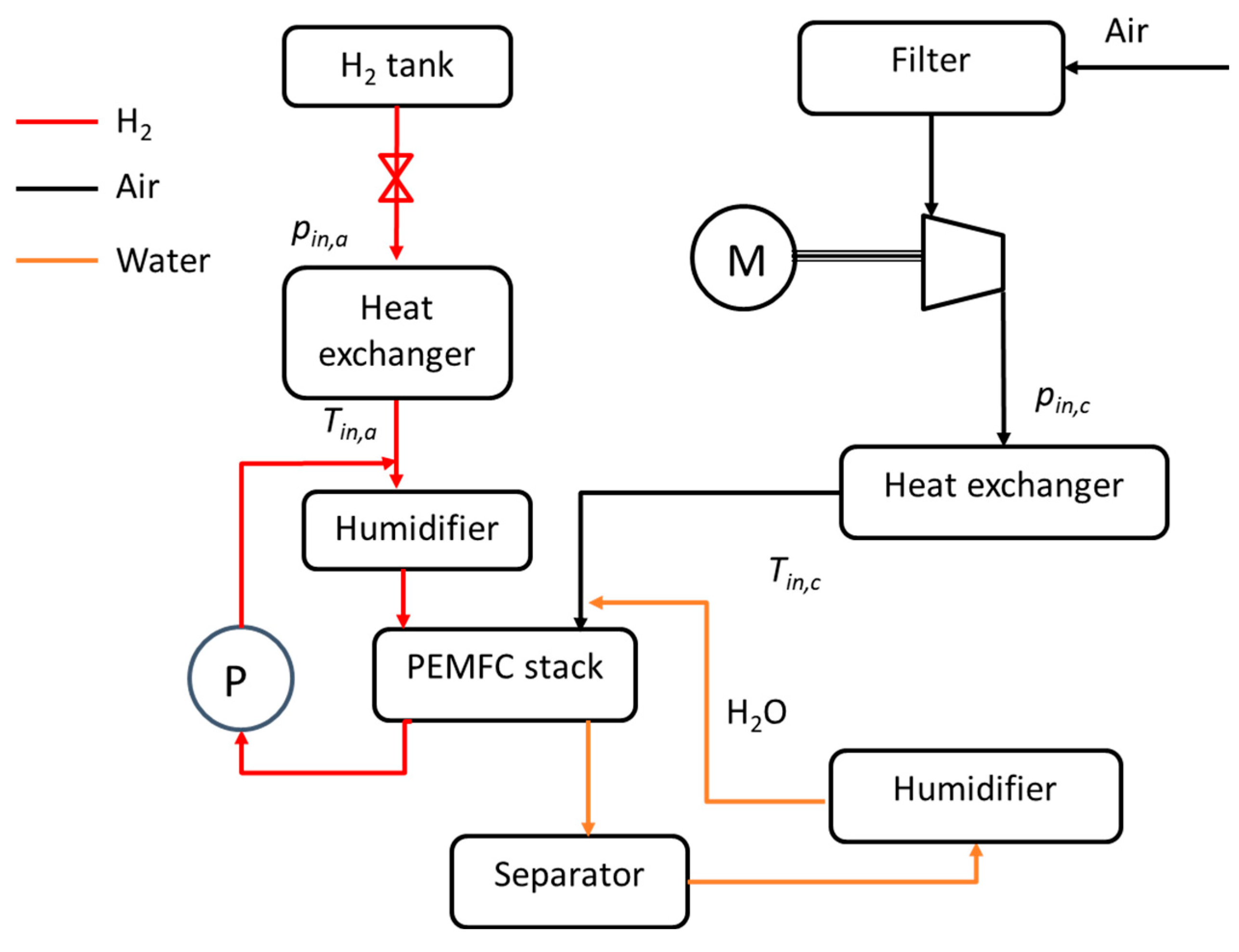
Figure 2.
Validation of the fuel cell stack model.
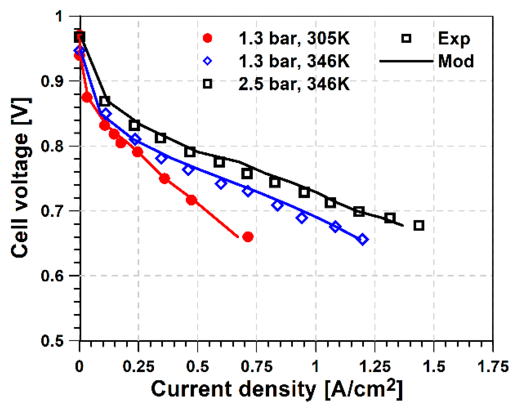
Figure 3.
Compressor performance maps. (A) isentropic efficiency map and (B) compressor speed map.
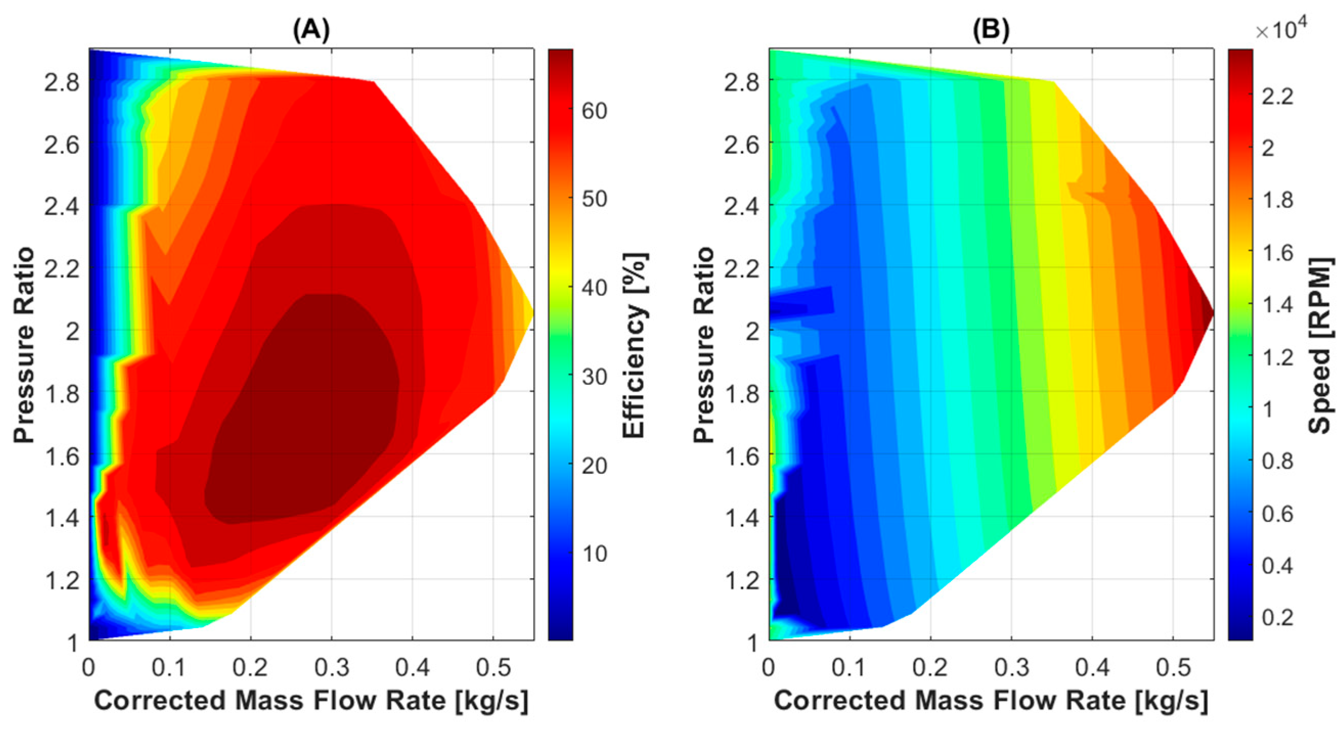
Figure 4.
Fuel cell stack and compressor operation as a function of the pressure ratio at sea level conditions. A) Fuel cell stack power B) Compressor power; C) Compressor efficiency.
Figure 4.
Fuel cell stack and compressor operation as a function of the pressure ratio at sea level conditions. A) Fuel cell stack power B) Compressor power; C) Compressor efficiency.
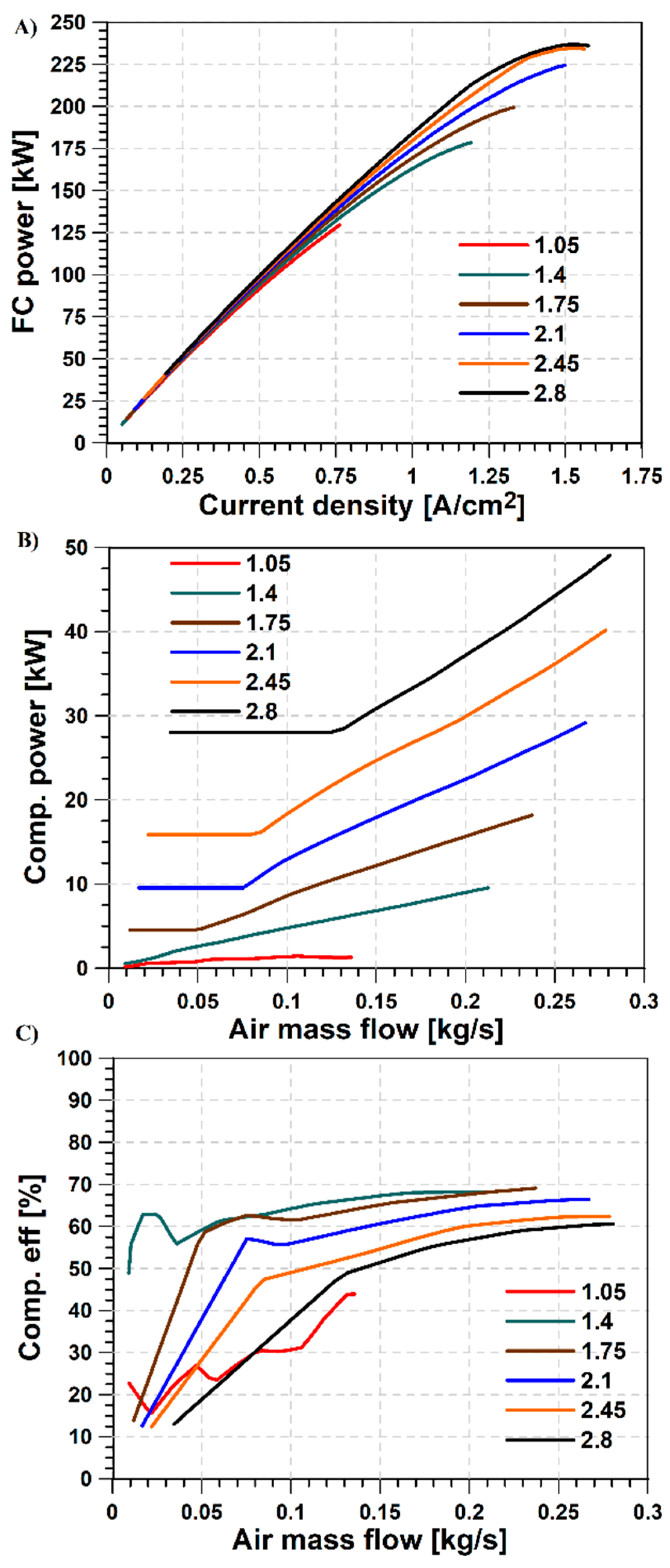
Figure 5.
Balance of plant efficiency as a function of the pressure ratio at sea level conditions.
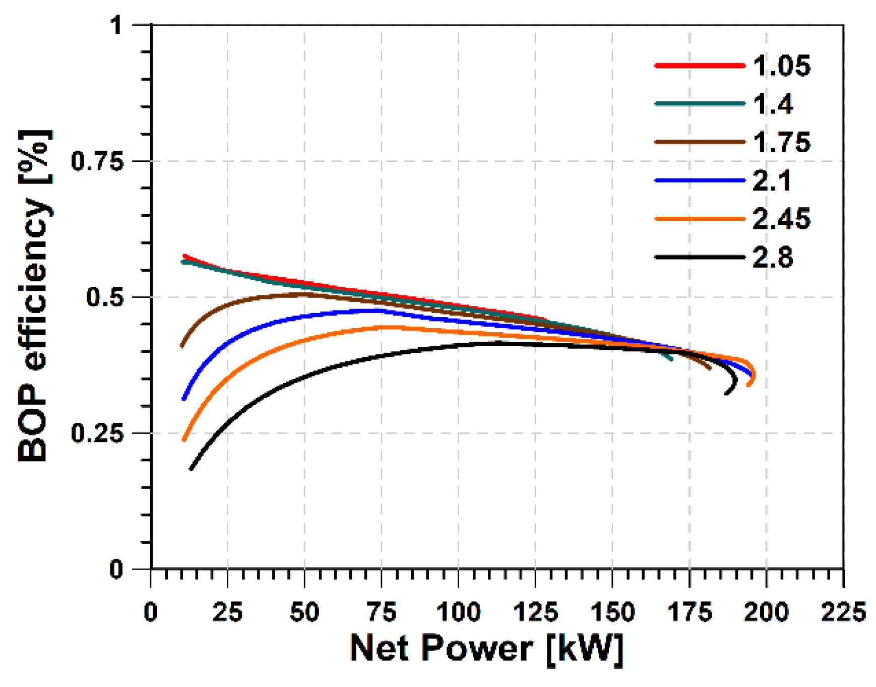
Figure 6.
Balance of plant efficiency and compressor as a function of the altitude. A) Optimal pressure ratio; B) Ratio of compressor power and net BOP power; C) BOP efficiency.
Figure 6.
Balance of plant efficiency and compressor as a function of the altitude. A) Optimal pressure ratio; B) Ratio of compressor power and net BOP power; C) BOP efficiency.
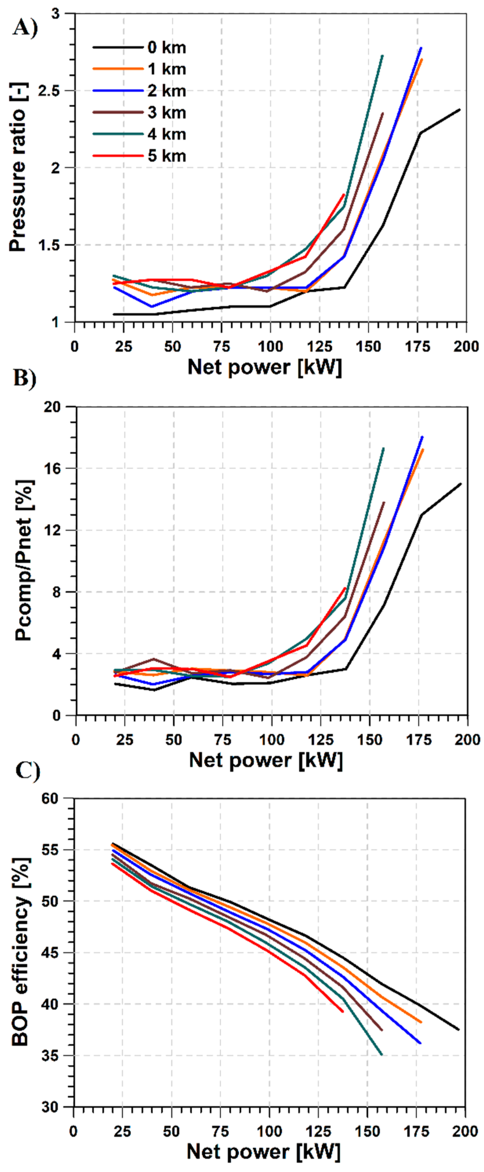
Figure 7.
Compressor working point a function of the altitude: A) pressure ratio vs. corrected mass flow; B) Efficiency vs. corrected mass flow.
Figure 7.
Compressor working point a function of the altitude: A) pressure ratio vs. corrected mass flow; B) Efficiency vs. corrected mass flow.
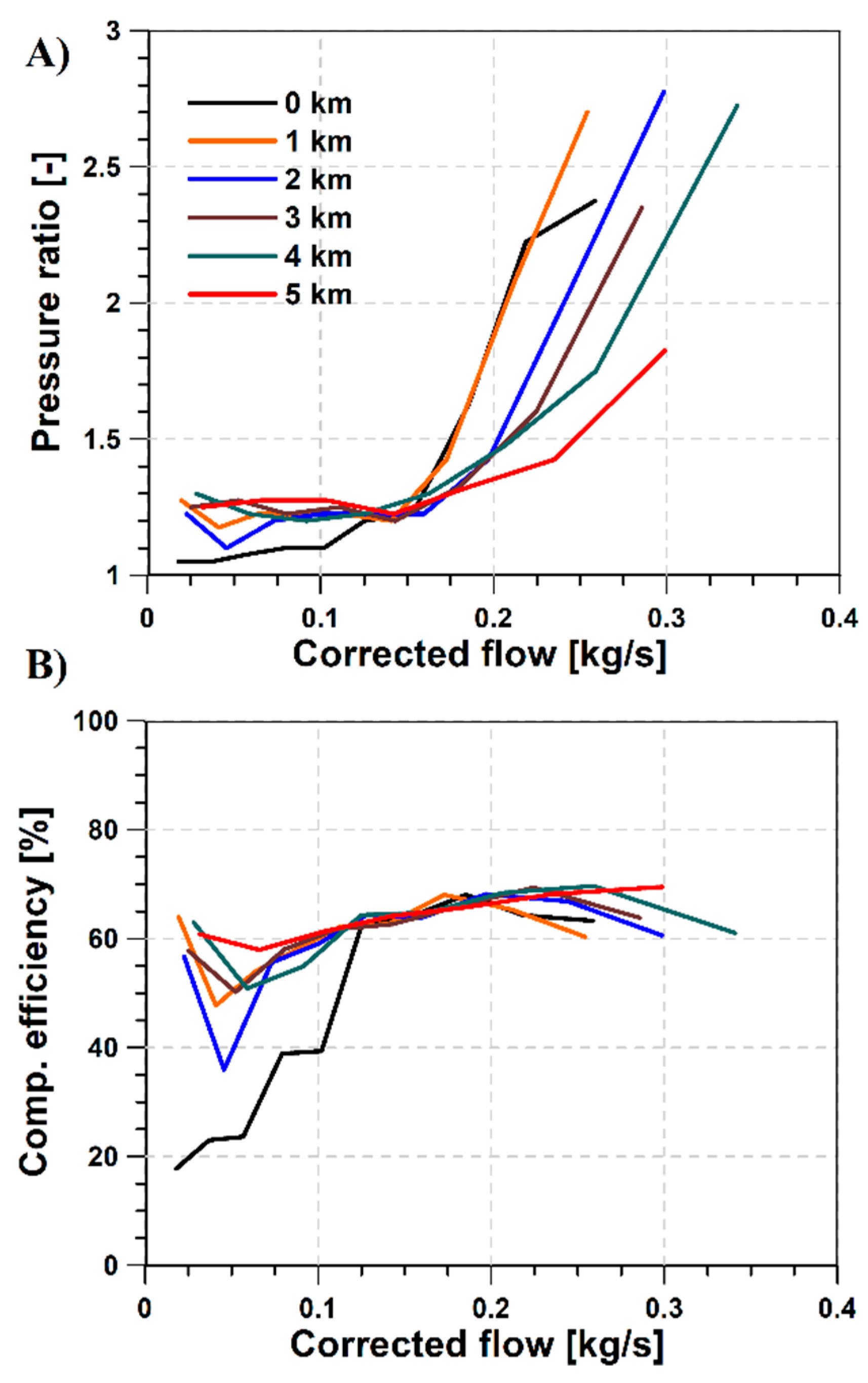
Figure 8.
Fuel cell stack operation a function of the altitude. A) Cathode inlet pressure; B) Fuel cell stack efficiency.
Figure 8.
Fuel cell stack operation a function of the altitude. A) Cathode inlet pressure; B) Fuel cell stack efficiency.
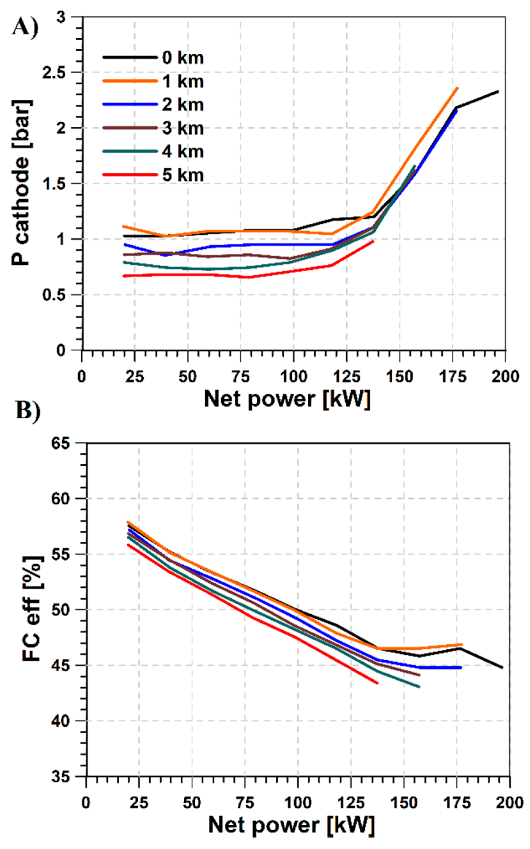

Table 1.
Fuel Cell Parameters.
| Parameter | Value (Units) |
|---|---|
| Number of cells in stack | 1000 |
| Cell area | 280 cm2 |
| Membrane thickness | 125 µm |
| Gas diffusion layer (GDL) thickness | 160 µm |
| Catalytic layer (CL) thickness | 10 µm |
| Symmetry factor | 0.5 |
| Density of dry membrane | 2000 kg/m3 |
| Equivalent weight of dry membrane | 1.1 kg/mol |
Disclaimer/Publisher’s Note: The statements, opinions and data contained in all publications are solely those of the individual author(s) and contributor(s) and not of MDPI and/or the editor(s). MDPI and/or the editor(s) disclaim responsibility for any injury to people or property resulting from any ideas, methods, instructions or products referred to in the content. |
© 2025 by the authors. Licensee MDPI, Basel, Switzerland. This article is an open access article distributed under the terms and conditions of the Creative Commons Attribution (CC BY) license (http://creativecommons.org/licenses/by/4.0/).
Copyright: This open access article is published under a Creative Commons CC BY 4.0 license, which permit the free download, distribution, and reuse, provided that the author and preprint are cited in any reuse.


