
Submitted:
01 April 2025
Posted:
04 April 2025
You are already at the latest version
Abstract
Supercapacitors (SCs) have attracted much attention due to their high-power density and long cycle life, where carbon materials have become the focus of electrode material research due to their excellent conductivity, stability, and reproducibility. However, the low specific capacitance and specific surface area of carbon materials lead to poor electrochemical properties, which seriously hinder their practical applications. The work here presents a simple but effective strategy to construct hollow nanocage structures by tannic acid etching ZIF-8. In this process, tannic acid releases protons to etch the MOF structure, and the remaining relatively large molecules are attached to the surface of ZIF-8 to prevent its structure from collapsing, and after high-temperature heat treatment, novel hollow nitrogen-doped carbon nanocage structures (HNCs) are obtained. Electrochemical tests show that the material has a capacity of 349.3 F g-1 at a current density of 0.5 A g-1, and still has a coulombic efficiency of 97.61% as well as a capacity retention of 97.86% after cycling for 10, 000 cycles at a current density of 3 A g-1. Therefore, this study provides a novel idea to explore the application of carbon materials with excellent electrochemical performance for energy storage.
Keywords:
supercapacitors
; metal-organic framework
; nano-hollow cage
; nitrogen doped carbon
; electrode materials
1. Introduction
With the development of the global economy, the traditional industrial structure has undergone an obvious transformation, and electronic products [1,2] can be found everywhere in people's lives. Especially, the rapid development of the new energy industry leads more people to pay attention to energy storage devices; therefore, it is of strategic significance to seek out clean [3], safe [4], and efficient energy storage technology [5]. As a novel energy storage device, supercapacitors address the limitations of low energy density of capacitors and low power density of secondary batteries. They have garnered significant attention due to their high power density, long cycle life, and rapid charging and discharging capabilities. In supercapacitors, they can be classified into two categories based on distinct charge storage mechanisms: double-layer capacitors [6,7,8] and pseudocapacitors [9,10,11]. Double-layer capacitors store energy via the electrochemical adsorption/desorption of electrostatic charges at the interface between the electrode and the electrolyte. In contrast, pseudocapacitance refers to the occurrence of reversible redox reactions on the surface and near the surface of the active electrode material to generate Faraday quasi-capacitance for store energy. Therefore, the choice of electrode materials is crucial for supercapacitors, which can directly affect the use of the device.
Carbon materials [12,13,14,15] have long been the most commonly used electrode materials for secondary batteries [16,17,18] and supercapacitors [19], with the advantages of high specific surface area, low cost, good electrical conductivity, and good electrochemical stability. However, the specific capacitance provided by carbon materials is very limited, and current studies have shown that structure modulation and heteroatom doping can significantly improve the electrochemical properties of carbon materials. Structure modulation primarily involves dimensional modulation, such as 0D materials [20,21], 1D materials [22,23], 2D materials [24,25], and 3D materials [24,26]. 0D materials, which are mainly composed of quantum dots and carbon quantum dots, exhibit advantages such as small size and larger contact area with the electrolyte. However, they suffer from lower conductivity and higher electrical resistance. 1D materials, including carbon nanotubes and nanowires, possess the benefits of lightweight properties and excellent mechanical stability, yet their conductivity is relatively low, and their chemical stability is insufficient. 2D materials, such as graphene and MXene, demonstrate superior electronic conductivity within the two-dimensional plane, high specific surface area, and structural stability. Nevertheless, they are prone to severe self-stacking, leading to a slow ion transport rate. 3D materials mainly include structures such as nanoflowers and metal-organic frameworks, which have the advantages of high specific surface area, low synthesis cost, easy functionalization, and other advantages in which the high specific surface area can effectively provide more active sites, more conducive to the energy storage and conversion of electrode materials. Heteroatom doping [27,28,29] is mainly introduced through in-situ carbonization, using high-temperature pyrolysis of nitrogen-containing precursors to introduce heteroatoms, and this method is simple to operate, easy to control, and can effectively regulate the specific capacity of carbon materials.
Metal-organic frameworks [30,31,32] (MOFs) and their derivatives serve as ideal precursors for fabricating electrode materials for high-performance supercapacitors, owing to their unique characteristics of high specific surface area and tunable pore structure. MOFs are a class of crystalline materials consisting of metal ions or metal clusters linked by organic ligands via coordination bonds, forming regular porous structures. The materials not only have high porosity and a tunable chemical composition but can also be transformed into porous carbon materials with high electrical conductivity by heat treatment. This transformation not only preserves the porous structure of MOFs but also introduces highly active electrochemical active sites, which provides a new idea for the design of supercapacitor electrode materials. Among them, ZIF-8 is composed of imidazole ligands and metal ions. Its structure features a high nitrogen content, large porosity, and excellent stability, making it an ideal precursor for the preparation of supercapacitor electrode materials. However, direct high-temperature carbonization of ZIF-8 results in electrode materials with limited electrochemical performance and specific surface area, which significantly hinders ion transport and transfer in the electrolyte. Therefore, the electrochemical properties of ZIF-8 can be effectively optimized through structural modification. Wei [33]et al. prepared complex nickel-cobalt-manganese sulfide yolk-shell hollow spheres via a simple self-templating strategy. These exhibit a high specific capacitance of 1, 360 F g-1 at 1 A g-1 and superior rate capability when utilized as electrode materials for electrochemical supercapacitors. Long [34] et al. developed lignin@ZIF-8-based carbon with hierarchical porous “core-shell” graphitized superstructure (KGC-EHL@ZIF-8) as an electrode material, achieving a maximum specific capacitance of 462.6 F g-1 at 0.5 A g-1 in a three-electrode system. Zhang [35] et al. employed nitrogen-sulfur co-doped ZIF-8 derivatives (NS-PCs) as the base material to fabricate high-performance, low self-discharge supercapacitor. Notably, the symmetric NS-PC-900//NS-PC-900 achieved a maximum specific capacitance of 42.7 F g-1. As a result, special materials are selected as templates or precursors to fabricate hollow nanostructures with unique structures to enhance their excellent electrochemical properties.
In this work, the novel hollow nitrogen-doped carbon nanocage structures (HNCs) are prepared by high-temperature pyrolysis of a composite precursor. ZIF-8 is employed as the framework precursor, while tannic acid served as both an etchant and a nitrogen source. The hollow nanocage structures (ZIF-8-TA) are obtained by compositing ZIF-8 with tannic acid at room temperature. During this process, protons released from tannic acid etched the MOF structure, while large molecules in tannic acid effectively stabilized the hollow nanocage structure, preventing its collapse. The resulting etched hollow nanocages exhibit a robust structural framework and rapid ion transport capability. They demonstrate a specific capacity of 349.3 F g-1 at a current density of 0.5 A g-1, a Coulombic efficiency of 97.61%, and a capacity retention of 97.86% after 10, 000 cycles at a current density of 3 A g-1. Therefore, the electrochemical properties of carbon materials can be effectively improved by structural modulation and heteroatom doping, which can further broaden their application prospects.
2. Experimental
2.1. Materials and Chemicals
Zinc nitrate hexahydrate (99.0%, Zn(NO3)2·6H2O) was purchased from Tianjin Damao Chemical Reagent Factory. Tannic acid and dimethylimidazole (98%) was purchased from Shanghai Maclean Biochemical Technology Co., Ltd. Methanol was obtained from Tianjin Best Chemical Co., Ltd. All reagents used in the experiments were of analytical grade, and the water used was homemade laboratory deionized water.
2.2. Synthesis of Materials
Synthesis of ZIF-8 precursor: ZIF-8 was synthesized by the traditional solvothermal method. Firstly, 1.116 g of zinc nitrate hexahydrate was dissolved in 30 mL of methanol solution, which was recorded as solution A. Separately, 1.232 g of dimethylimidazole was dissolved in 30 mL of methanol solution to prepare solution B. Subsequently, solutions A and B were homogeneously mixed and ultrasonically dispersed for 6 min to ensure complete dissolution and uniform distribution. The resulting mixture (solution AB) was then transferred to a 100 mL stainless steel autoclave lined with PTFE. The sealed autoclave was heated at 120 ℃ for 2 h in an oven. After cooling to room temperature, the product was collected by centrifugation, washed sequentially with methanol and deionized water, and finally dried in a vacuum oven at 60 ℃. The final product was obtained as ZIF-8.
Synthesis of ZIF-8-TA:Take 0.1 g of the above ZIF-8 material and put it in 1 g L-1 tannic acid (TA) solution, after aging for 10 min, the product was washed with methanol and deionized water, and finally put into a 60 ℃ vacuum oven to dry, and finally the product ZIF-8-TA was obtained.
Synthesis of NCs:The dried ZIF-8 was pyrolysis at 800 °C for 2 h in a nitrogen atmosphere to finally obtain NCs.
Synthesis of HNCs:The dried ZIF-8-TA-X was subjected to pyrolysis at 800 °C for 2 h under a nitrogen atmosphere, resulting in the final production HNCs. The numbers indicate varying concentrations of tannic acid (for example, number 8 corresponds to a tannic acid concentration of 8 g L-1).
2.3. Materials Characterizations
The structural characteristics were typically analyzed using transmission electron microscopy (TEM, JEM-F200) and scanning electron microscopy (SEM, JSM-6701F). Powder X-ray diffraction (XRD) data were collected with a D/MAX-2400 diffractometer within the range of 5-90°, employing a step size of 0.02 and a scanning speed of 10°/min. X-ray photoelectron spectroscopy (XPS) measurements were performed using a VG ESCALAB 250 Xi spectrometer.
2.4. Electrochemical Measurements
Single Electrode Testing:preparation of the working electrode involved a mass ratio of 80% active electrode material, 7.5% acetylene black, 7.5% graphite, and 5% polytetrafluoroethylene (PTFE). These components were mixed and stirred to form a uniform paste. During the mixing process, a small amount of alcohol was added to aid dispersion. The resulting paste was then coated onto a 1 cm² area of nickel foam substrate to fabricate the working electrodes, with each electrode containing 4 mg of active material. Following this, the electrodes were dried under vacuum at 60 ºC for 8 hours and subsequently pressed at 10 MPa for 30 seconds to enhance the contact between the active material and the current collector. The electrochemical properties of the electrodes were evaluated at room temperature using a CHI660E electrochemical workstation (Shanghai Chenhua, China). The testing setup included a 6 M potassium hydroxide electrolyte and a platinum sheet as the counter electrode in a single-electrode configuration. Cyclic voltammetry measurements were performed at various scan rates ranging from 5-50 mV s-1. Additionally, constant current charging and discharging tests were conducted at current densities varying from 0.5-5 A g-1. Electrochemical impedance spectroscopy (EIS) analysis were carried out within a frequency range of 10-2-105 Hz. For cyclic stability assessment the LAND CT2001A system was employed, and the specific capacitance was usually typically using equation (1):
where C (F g-1) was the specific capacitance, I (A) was the current, m (mg) was the mass of the active substance, ΔV (V) was the voltage window, and Δt (s) was the discharging time.
3. Results and Discussion
Figure 1a presents a schematic illustration of the synthesis of HNCs. firstly, the ZIF-8 precursor is prepared by the solvothermal method followed by etching the precursor using tannic acid. The tannic acid is exploited to release free protons that can be used to etch the MOF framework. Where the relatively large molecular size can block the pores of the MOF structure and ensure that the structure does not collapse completely. Meanwhile, the larger molecular size attached to the MOF surface can change the MOF surface from hydrophobicity to hydrophilicity, which greatly improves the practical value of the MOF material. Then the ZIF-8 material is etched by choosing different concentrations of tannic acid so as to achieve the purpose of constructing a special structure. By pyrolysis of the etched material ZIF-8-TA at high-temperature, the hollow nitrogen-doped carbon nanocage structure is finally obtained, which can be applied in the electrode material of supercapacitors.
Figure 1b shows the XRD spectra [36] of ZIF-8 and samples etched with different concentrations of tannic acid. It is evident that tannic acid etching significantly reduces the intensity of the diffraction peaks of the ZIF-8 precursor, indicating that the etching process does not alter the original composition or structure of ZIF-8. Figure 1c shows an enlarged spectrum of the XRD from 5º to 30º, clearly demonstrating that as the concentration of tannic acid increases, the diffraction peaks of the ZIF-8 precursor become progressively weaker. Figure 1d shows the XRD spectrum after carbonation, in which obvious broad peaks appeared at 23º and 43º, which is mainly attributed to the formation of amorphous carbon and proves that the composites are successfully prepared.
X-ray photoelectron spectroscopy (XPS) is employed to analyze the elemental composition and ratios within the materials. As illustrated in Figure 2a, the XPS spectra of NCs and HNCs reveal the presence of four elements: C, N, O, and Zn. Among these, carbon exhibits the highest concentration, primarily due to the conversion of organic ligands in the precursors into carbon-based materials under high-temperature conditions. The specific ratios of these elements are detailed in Table S1. Figure 2b presents the detailed spectra of high-resolution NCs and HNCs. The high-resolution XPS spectra of Zn 2p can be separated into the following bonds: 1045.3 eV (Zn 2p1/2) and 1022.2 eV (Zn 2p3/2) [36]. By comparing the NCs and HNCs, it is evident that the intensity of the Zn element’s peaks is significantly reduced after etching. This indicates that tannic acid can remove a portion of the zinc ions, thus increasing the volume fraction per unit mass and laying a certain foundation for the excellent electrochemical performance. Figure 2c–e presents the detailed high-resolution spectra of NCs. The C 1s high-resolution XPS spectra can be separated into distinct peaks corresponding to the following bonds: 285 eV (C-C/C=C), 285.9 eV (C-N), and 287.8 eV (C-O). For the N 1s high-resolution XPS spectra, the deconvolution reveals the presence of bonds at 397.7 eV (pyridinic nitrogen), 400 eV (pyrrolic nitrogen), and 401.4 eV (graphitic nitrogen) [37]. Likewise, Figure 2f–h illustrates the fine spectra of HNCs. By analyzing and comparing the fine spectra of C 1s, N 1s, and O 1s, the presence of fitted C-N, C-O, O-H, and C=C bonds confirms the successful synthesis of the ZIF-8 precursor and the etched material. The analysis of the elemental content reveals that there is a significant decrease in the content of zinc after etching, corresponding to an increase in the content of carbon, which is in agreement with the conclusions obtained from XRD.
To further investigate the effect of structure on the properties, Figure 3a–f presents field emission electron microscopy images of ZIF-8, ZIF-8-TA-1, and ZIF-8-TA-8. Figure 3a,b show the scanning electron micrographs of ZIF-8 before and after carbonization. It is evident that the prepared precursor has a uniform dodecahedral structure. Furthermore, the individual structures are preserved at nanostructures, with no formation of hollow structures observed either before or after carbonization. This confirms the successful preparation of the precursor ZIF-8. Figure S2 shows the EDS mapping analysis of precursor ZIF-8 after carbonization, and it can be found that the four elements, C, O, N, and Zn, are uniformly distributed, with the contents of C (89.96%), N (1.06%), O (8.34%), and Zn (0.64%) (Table S2). Figure 3c,d display the scanning electron micrographs of ZIF-8-TA-1 before and after carbonization. These images reveal that etching of the ZIF-8 precursor by a small dose of tannic acid is not obvious. However, a portion of the inner part of the structure of ZIF-8-TA-1 is etched away with respect to the precursor, which can also be demonstrated that the tannic acid etching is from the outside to the inside, which is a further demonstration of the controllable nature of the hollow nano-cage structure. Figure S1a–d show the scanning electron micrographs of ZIF-8-TA-2 and ZIF-8-TA-4 before and after carbonization, and it can be observed that the etching effect is more obvious with the increase of tannic acid etchant. Figure 3e,f show the scanning electron micrographs of ZIF-8-TA-8 before and after carbonization. It is evident that a hollow nanocage structure forms when the concentration of tannic acid reaches 8 mg mL-1, thereby validating the feasibility of this strategy. Figure S3 shows the EDS mapping analysis of HNCs-8 with C (97.98%), N (1.03%), and O (0.99%) (Table S2), which is in agreement with the XPS test results in Figure 2. Given that the hollow structure is composed of inner and outer layers, this structure can give the material a larger specific surface area as well as active sites, which will be favorable for the adsorption and desorption of ions. Moreover, the nanosized structure can effectively shorten the ion transport path and effectively improve the efficiency of the electrode material.
Figure 4a–f shows the transmission electron microscope (TEM) images of ZIF-8, ZIF-8-TA-1, and ZIF-8-TA-8 after carbonization, which are named as NCs, HNCs-1, and HNCs-8, respectively. Figure 4a,b illustrates the TEM pictures of the ZIF-8 precursor after carbonation. Due to the chelation between metal ions and organic ligands forming ZIF-8 nanoparticles, it can be observed that the precursor after carbonization has a morphology consistent with that observed in scanning electron microscopy, which are all dodecahedral in structure, which indicates that the preparation of the precursor for this material is successful. A high density of pores on the surface of the carbonization NCs can be observed in the HRTEM of Figure 4b, and this porous structure offers a promising potential for the development of high-capacity electrode materials. With the introduction of tannic acid as an etchant, the dodecahedral structure of HNCs-1 in Figure 4c can be observed to gradually undergo etching. Compared to the dodecahedral structure of NCs, HNCs-1 gradually transitions to the hollow structure to produce the core-shell structure. It is due to the release of free protons by the tannic acid that the effect of etching is produced on the structure of the NCs, the larger molecular size of the tannic acid effectively prevents the destruction of the shells, the core-shell structure of the HNCs-1 material is further observed in the HRTEM of Figure 4d, and proving the feasibility of this strategy. As the concentration of tannic acid increased, the etching effect became more significant. Figure S4a,b show the TEM images of HNCs-2. In Figure S4a, it can be observed that the core-shell structure produced by etching has changed significantly compared with HNCs-1, and the nucleus structure of HNCs-2 is gradually becoming smaller. Figure S4b shows the HRTEM images, where it is evident that HNCs-2 exhibits a more abundant pore distribution on its surface. This feature can effectively improve the reaction kinetics of electrode materials. Figure S4c,d shows the TEM images of HNCs-4, revealing a further reduction in the nuclear structure, which validates the feasibility of the tannic acid etching precursor strategy. With the further increase of etchant content, Figure 4e,f displays the TEM pictures of HNCs-8, where it can be found that the nucleus structure has disappeared, generating a hollow nano-hollow cage structure, which has a larger specific surface area relative to the NCs and can generate more active sites, which can effectively shorten the ionic transport paths and optimize the interfacial reaction kinetics.
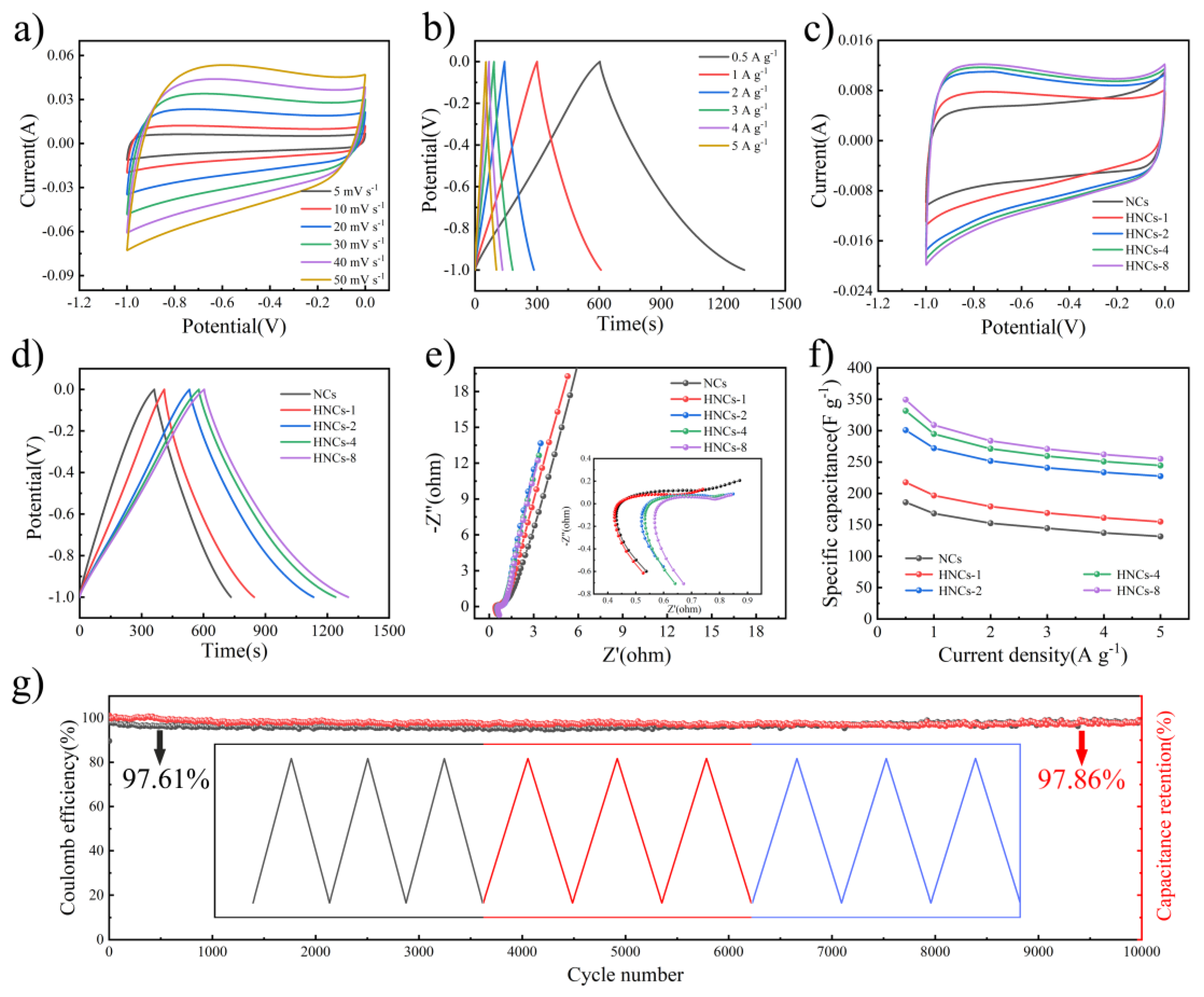
In order to verify the potential of HNCs for electrochemical applications, the electrochemical properties of HNCs as electrode materials are explored. The NCs and HNCs samples with varying compositions are employed as working electrodes for single electrode testing. These electrodes undergo characterization through cyclic voltammetry (CV), constant current charging and discharging curves (GCD), and electrochemical impedance spectroscopy (EIS) to assess their performance [38]. Figure S5a shows the CV curves of the NCs at scan rates ranging from 5-50 mV s-1, and the obvious rectangle-like characteristics of the CV curves can be observed, without obvious redox peaks. In Figure S5b, the GCD test reveals that the curves exhibit excellent symmetry, so it also proves that the NCs material is more reversible and exhibits good double layer capacitance characteristics. The discharging process is carried out at current densities ranging from 0.5 to 5 A g-1. The capacities of the NCs are calculated using equation (1), yielding values of 185.8 F g-1, 168.1 F g-1, 152.6 F g-1, 144.6 F g-1, 137.2 F g-1, and 131.5 F g-1, respectively. After carbonization, ZIF-8 maintains its dodecahedral morphology along with its porous architecture, which enhances the electrochemical performance of the NCs. The CV and GCD curves for HNCs-1, HNCs-2, and HNCs-4 are presented in Figure S5c,d, Figure S5e,f, and Figure S6a,b respectively. These figures indicate that the electrochemical characteristics of HNCs-1, HNCs-2, and HNCs-4 vary significantly with alterations in the quantity of tannic acid. Figure 5a,b shows the CV and GCD test curves of HNCs-8, a rectangular shape curve can be observed in the CV curve in Figure 5a, indicating that the energy storage mechanism of this material is consistent with that of the NCs material, which is attributed to the capacitive behavior of the double layer. Figure 5b presents the GCD curves of HNCs-8 under different current densities, demonstrating its excellent reversibility. The specific capacities of the HNCs-8 are calculated using equation (1) and are found to be 349.3 F g-1, 308.9 F g-1, 283.8 F g-1, 270.9 F g-1, 262.0 F g-1, and 255.0 F g-1, respectively. Compared with the NCs precursor electrode material, the specific capacity of HNCs-8 is enhanced by nearly two times at a current density of 0.5 A g-1, which validates the feasibility of preparing hollow nanocage structures by tannic acid etching. Figure 5c illustrates the comparison of CV curves for different tannic acid contents, through which it can be found that the electrochemical properties exhibited by different electrode materials are consistent. Figure 5d shows the comparison of GCD with different tannic acid contents, and it can be found that the area of HNCs-8 is the largest, and the discharge time is the longest, and therefore the electrochemical performance of HNCs-8 is also the most superior. Following this, EIS analysis is performed as shown in Figure 5e, revealing that the slope of the material is significantly steeper in the low-frequency region. This characteristic confirms the superior conductivity of carbon materials. In the high-frequency region, both the radius of the semicircular region (charge transfer resistance, Rct) and the x-axis intercept (intrinsic impedance, Rs) are notably small, suggesting that the material possesses exceptional ion transport capabilities. As depicted in Figure 5f, the rate performance of various samples is evaluated at multiple current densities. It is evident that HNCs-8 demonstrates the highest specific capacity across different current densities. Figure 5g shows the long-cycle test of HNCs-8, and it can be found that HNCs-8 still has a relatively stable Coulombic efficiency and capacity retention after cycling at a current density of 3 A g-1 for 10, 000 cycles. Therefore, the electrochemical test reveals that that the electrochemical performance of HNCs-8 is significantly enhanced compared to that of carbon NCs, further demonstrating the potential of nano-hollow spheres for long-life energy storage devices.
4. Conclusions
In summary, this work successfully demonstrates the feasibility of constructing hollow nanocage structures by etching ZIF-8 with tannic acid. In this process, tannic acid releases protons to etch the MOF structure while its relatively large molecules adsorb onto the surface of ZIF-8, thereby stabilizing its structure and preventing collapse. After high-temperature heat treatment, novel hollow nitrogen-doped carbon nanocage structures (HNCs) are obtained. This structure has a capacity of 349.3 F g-1 at a current density of 0.5 A g-1 and still has a Coulombic efficiency of 97.61% and a capacity retention of 97.86% after cycling 10, 000 cycles at a current density of 3 A g-1. Thus, the electrochemical properties of carbon materials can be significantly enhanced through structural modulation and heteroatom doping. This innovative structure offers insights into the development of next-generation electrode materials, showcasing extensive application potential.
Supplementary Materials
The following supporting information can be downloaded at the website of this paper posted on Preprints.org.
Acknowledgments
This work is supported by Natural Science Foundation of Gansu Province (No. 22JR11RM167, 22JR5RM203, and 24JRRM04), Youth Science and Technology Fund of Gansu Province (No. 20JR10RA137), Key Research and Development Program of Gansu Province-Industry Project (No. 25YFGM001), Young Doctor Support Project of Gansu Province (2024QB-117), and Key Research and Development Program of Qingyang City-Industry Project (No. QY-STK-2024A-141).
References
- Wang, X.; Lu, X.; Liu, B.; et al. Flexible Energy-Storage Devices: Design Consideration and Recent Progress. Advanced Materials 2014, 26, 4763–4782. [Google Scholar] [CrossRef] [PubMed]
- Zhang, X.; Jiang, C.; Liang, J.; et al. Electrode materials and device architecture strategies for flexible supercapacitors in wearable energy storage. Journal of Materials Chemistry A 2021, 9, 8099–8128. [Google Scholar] [CrossRef]
- Ni, C.; Xue, X.; Mei, S.; et al. Technological Research of a Clean Energy Router Based on Advanced Adiabatic Compressed Air Energy Storage System. Entropy 2020, 22, 1440. [Google Scholar] [CrossRef] [PubMed]
- Sharma, S.; Ghoshal, S.K. Hydrogen the future transportation fuel: From production to applications. Renewable & Sustainable Energy Reviews 2015, 43, 1151–1158. [Google Scholar]
- Zheng, Q.; Jiang, L.; Xu, Y.; et al. Research Progress and Development Suggestions of Energy Storage Technology under Background of Carbon Peak and Carbon Neutrality. Bulletin of the Chinese Academy of Sciences 2022, 37, 529–540. [Google Scholar]
- Gupta, A.; Zuk, P.J.; Stone, H.A. Charging Dynamics of Overlapping Double Layers in a Cylindrical Nanopore. Physical Review Letters 2020, 125, 076001. [Google Scholar] [CrossRef]
- Schiffer, J.; Linzen, D.; Sauer, D.U. Heat generation in double layer capacitors. Journal of Power Sources 2006, 160, 765–772. [Google Scholar] [CrossRef]
- Volfkovich, Y.M. Electric Double Layer Capacitors: A Review. Russian Journal of Electrochemistry 2024, 60, 761–794. [Google Scholar] [CrossRef]
- Chen, W.; Rakhi, R.B.; Alshareef, H.N. Facile synthesis of polyaniline nanotubes using reactive oxide templates for high energy density pseudocapacitors. Journal of Materials Chemistry A 2013, 1, 3315–3324. [Google Scholar] [CrossRef]
- Mahala, S.; Khosravinia, K.; Kiani, A. Unwanted degradation in pseudocapacitors: Challenges and opportunities. Journal of Energy Storage 2023, 67, 107558. [Google Scholar] [CrossRef]
- Gu, T.; Wei, B. Fast and stable redox reactions of MnO2/CNT hybrid electrodes for dynamically stretchable pseudocapacitors. Nanoscale 2015, 7, 11626–11632. [Google Scholar] [CrossRef] [PubMed]
- Chen, H.; Liu, D.; Shen, Z.; et al. Functional Biomass Carbons with Hierarchical Porous Structure for Supercapacitor Electrode Materials. Electrochimica Acta 2015, 180, 241–251. [Google Scholar] [CrossRef]
- Dingsheng, Y.; Xiangchun, H.U.; Yingliang, L.I.U.; et al. Research progress in carbon materials for supercapacitors. Battery 2007, 37, 466–468. [Google Scholar]
- Wang, D.-W.; Li, F.; Cheng, H.-M. Hierarchical porous nickel oxide and carbon as electrode materials for asymmetric supercapacitor. Journal of Power Sources 2008, 185, 1563–1568. [Google Scholar] [CrossRef]
- Yan, D.; Liu, L.; Wang, X.; et al. Biomass-Derived Activated Carbon Nanoarchitectonics with Hibiscus Flowers for High-Performance Supercapacitor Electrode Applications. Chemical Engineering & Technology 2022, 45, 649–657. [Google Scholar]
- Buller, S.; Thele, M.; De Doncker, R.; et al. Impedance-based simulation models of supercapacitors and Li-ion batteries for power electronic applications. Ieee Transactions on Industry Applications 2005, 41, 742–747. [Google Scholar] [CrossRef]
- Cherusseri, J.; Pandey, D.; Thomas, J. Symmetric, Asymmetric, and Battery-Type Supercapacitors Using Two-Dimensional Nanomaterials and Composites. Batteries & Supercaps 2020, 3, 860–875. [Google Scholar]
- Libich, J.; Sedlarikova, M.; Maca, J.; et al. Supercapacitors vs. Lithium-ion Batteries: Properties and Applications. Chemie Ingenieur Technik 2024, 96, 279–285. [Google Scholar] [CrossRef]
- Yan, J.; Li, S.; Lan, B.; et al. Rational Design of Nanostructured Electrode Materials toward Multifunctional Supercapacitors. Advanced Functional Materials 2020, 30, 1902564. [Google Scholar] [CrossRef]
- Kumar, S.; Saeed, G.; Zhu, L.; et al. 0D to 3D carbon-based networks combined with pseudocapacitive electrode material for high energy density supercapacitor: A review. Chemical Engineering Journal 2021, 403, 126352. [Google Scholar] [CrossRef]
- Kadam, V.A.; Patil, V.L.; Mujawar, S.H.; et al. Recent advances of spinel CuCo2O4 in different Structural dimensions (0D-3D) for an electrochemical supercapacitor device: A short research review. Journal of Alloys and Compounds 2025, 1010. [Google Scholar] [CrossRef]
- Ouyang, T.; Cheng, K.; Yang, F.; et al. From biomass with irregular structures to 1D carbon nanobelts: a stripping and cutting strategy to fabricate high performance supercapacitor materials. Journal of Materials Chemistry A 2017, 5, 14551–14561. [Google Scholar] [CrossRef]
- Sankar, K.V.; Lee, S.C.; Seo, Y.; et al. Binder-free cobalt phosphate one-dimensional nanograsses as ultrahigh-performance cathode material for hybrid supercapacitor applications. Journal of Power Sources 2018, 373, 211–219. [Google Scholar] [CrossRef]
- Sandhu, A.; Chini, M.K. 2D and 3D Halide Perovskite-Based Supercapacitors. Chemistryselect 2024, 9, e202304441. [Google Scholar] [CrossRef]
- Tian, X. Direct ink writing of 2D material-based supercapacitors. 2D Materials 2021, 9, 012001. [Google Scholar] [CrossRef]
- Chang, J.; Yue, H.; Zhang, H.; et al. Three-dimensional graphene:preparation and application in supercapacitor. New Chemical Materials 2016, 44, 9–11. [Google Scholar]
- Chen, K.; Huang, X.; Wan, C.; et al. Efficient oxygen reduction catalysts formed of cobalt phosphide nanoparticle decorated heteroatom-doped mesoporous carbon nanotubes. Chemical Communications 2015, 51, 7891–7894. [Google Scholar] [CrossRef]
- Li, W.; Zhang, W.; Xu, Y.; et al. Heteroatom-doped lignin derived carbon materials with improved electrochemical performance for advanced supercapacitors. Chemical Engineering Journal 2024, 497, 22346–22371. [Google Scholar] [CrossRef]
- Zhang, P.; Mu, J.; Kong, X.; et al. Novel Electrode Materials and Redox-Active Electrolyte for High-Performance Supercapacitor. Chemelectrochem 2022, 9, e202101646. [Google Scholar] [CrossRef]
- Calik, F.D.; Erdogan, B.; Yilmaz, E.; et al. Photocatalytic degradation of aquatic organic pollutants with Zn- and Zr-based metal- organic frameworks: ZIF-8 and UiO-66. Turkish Journal of Chemistry 2022, 46, 1358–1375. [Google Scholar] [CrossRef]
- Saint Remi, J.C.; Remy, T.; Van Hunskerken, V.; et al. Biobutanol Separation with the Metal-Organic Framework ZIF-8. Chemsuschem 2011, 4, 1074–1077. [Google Scholar] [CrossRef]
- Wang, X.; Li, M.; Cao, C.; et al. Surfactant-Free Palladium Nanoparticles Encapsulated in ZIF-8 Hollow Nanospheres for Size-Selective Catalysis in Liquid-Phase Solution. Chemcatchem 2016, 8, 3224–3228. [Google Scholar] [CrossRef]
- Wei, C.; Sun, J.; Zhang, Y.; et al. Hierarchical Ni(OH)2-MnO2 hollow spheres as an electrode material for high-performance supercapacitors. Inorganic Chemistry Frontiers 2022, 9, 3542–3551. [Google Scholar] [CrossRef]
- Long, Y.; An, X.; Zhang, H.; et al. Highly graphitized lignin-derived porous carbon with hierarchical N/O co-doping "core-shell" superstructure supported by metal-organic frameworks for advanced supercapacitor performance. Chemical Engineering Journal 2023, 451, 138877. [Google Scholar] [CrossRef]
- Zhang, H.; Fang, L.; Guo, Y.; et al. Nitrogen-sulfur co-doped ZIF-8-derived carbon materials for supercapacitors with low self-discharge. Journal of Energy Storage 2024, 80, 110138. [Google Scholar] [CrossRef]
- Chen, G.; Jin, B.; Sun, S.; et al. Surface-functionalized metal-organic framework with high specific surface area optimizing composite solid electrolyte for high-performance solid-state lithium metal batteries. Chemical Engineering Journal 2024, 501, 157704. [Google Scholar] [CrossRef]
- Cai, C.; Zou, Y.; Xiang, C.; et al. Broccoli-like porous carbon nitride from ZIF-8 and melamine for high performance supercapacitors. Applied Surface Science 2018, 440, 47–54. [Google Scholar] [CrossRef]
- Dang, H.; Wang, L.; Ran, F. Polydopamine supporting method fabricating vanadium nitride nanoparticle enclosed into hierarchical hollow carbon nanospheres for supercapacitors. Journal of Power Sources 2024, 606, 234546. [Google Scholar] [CrossRef]
Figure 1.
(a) Schematic diagram of HNCs composite material preparation. (b) XRD patterns of the precursor without etching and after etching with different concentrations of tannic acid. (c) Partial diffraction magnification image of ZIF-8, ZIF-8-TA-1, ZIF-8-TA-2, ZIF-8-TA-4 and ZIF-8-TA-8. (d) XRD patterns after carbonation of NCs, HNCs-1, HNCs-2, HNCs-4, and HNCs-8.
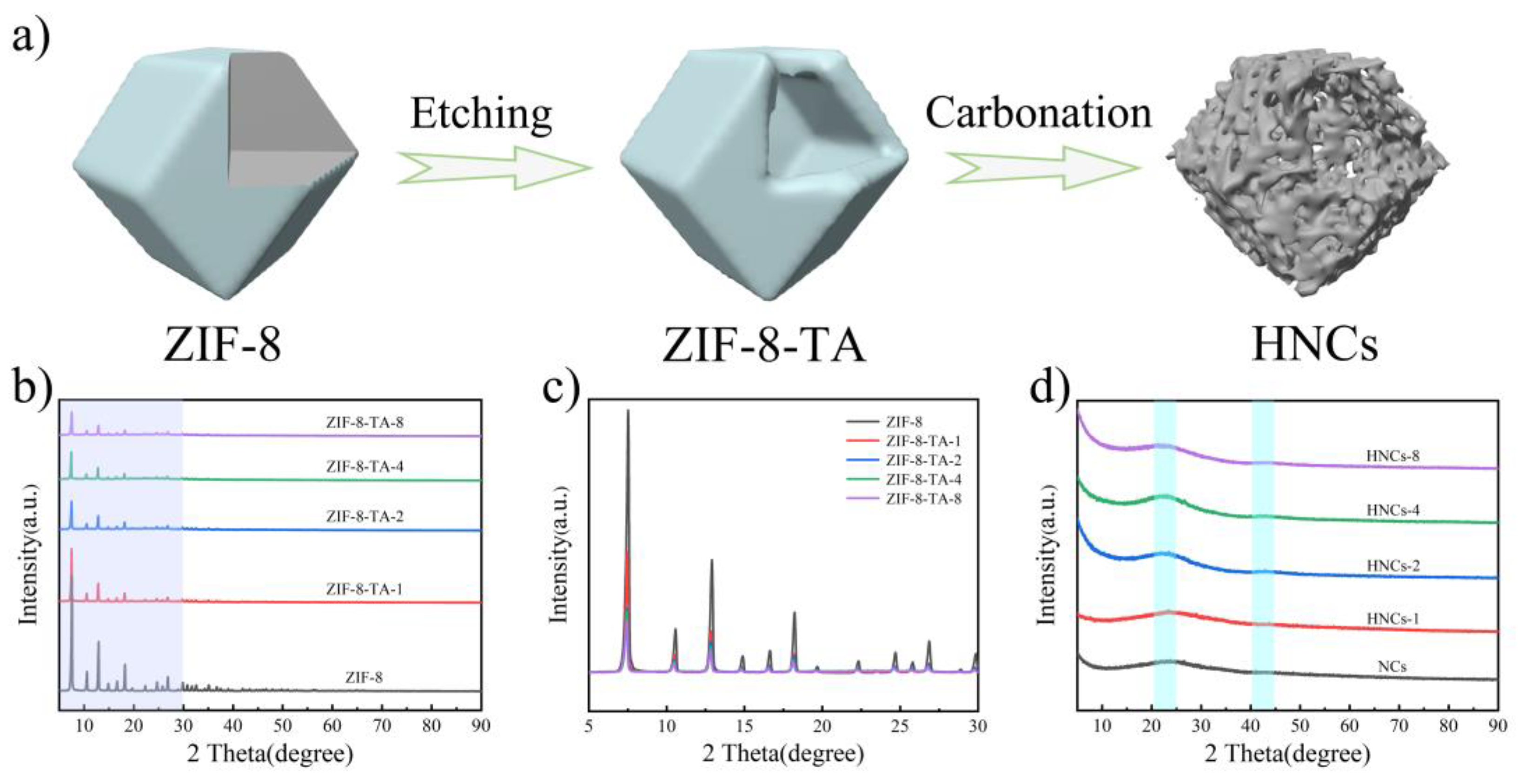
Figure 2.
(a) The XPS total spectrum of NCs and HNCs-8. XPS high-resolution spectra of (b) Zn 2p, (c) C 1s, (d) N 1s, and (e) O 1s of NCs. XPS high-resolution spectra of (b) Zn 2p, (f) C 1s, (g) N 1s, and (h) O 1s of HNCs.
Figure 2.
(a) The XPS total spectrum of NCs and HNCs-8. XPS high-resolution spectra of (b) Zn 2p, (c) C 1s, (d) N 1s, and (e) O 1s of NCs. XPS high-resolution spectra of (b) Zn 2p, (f) C 1s, (g) N 1s, and (h) O 1s of HNCs.
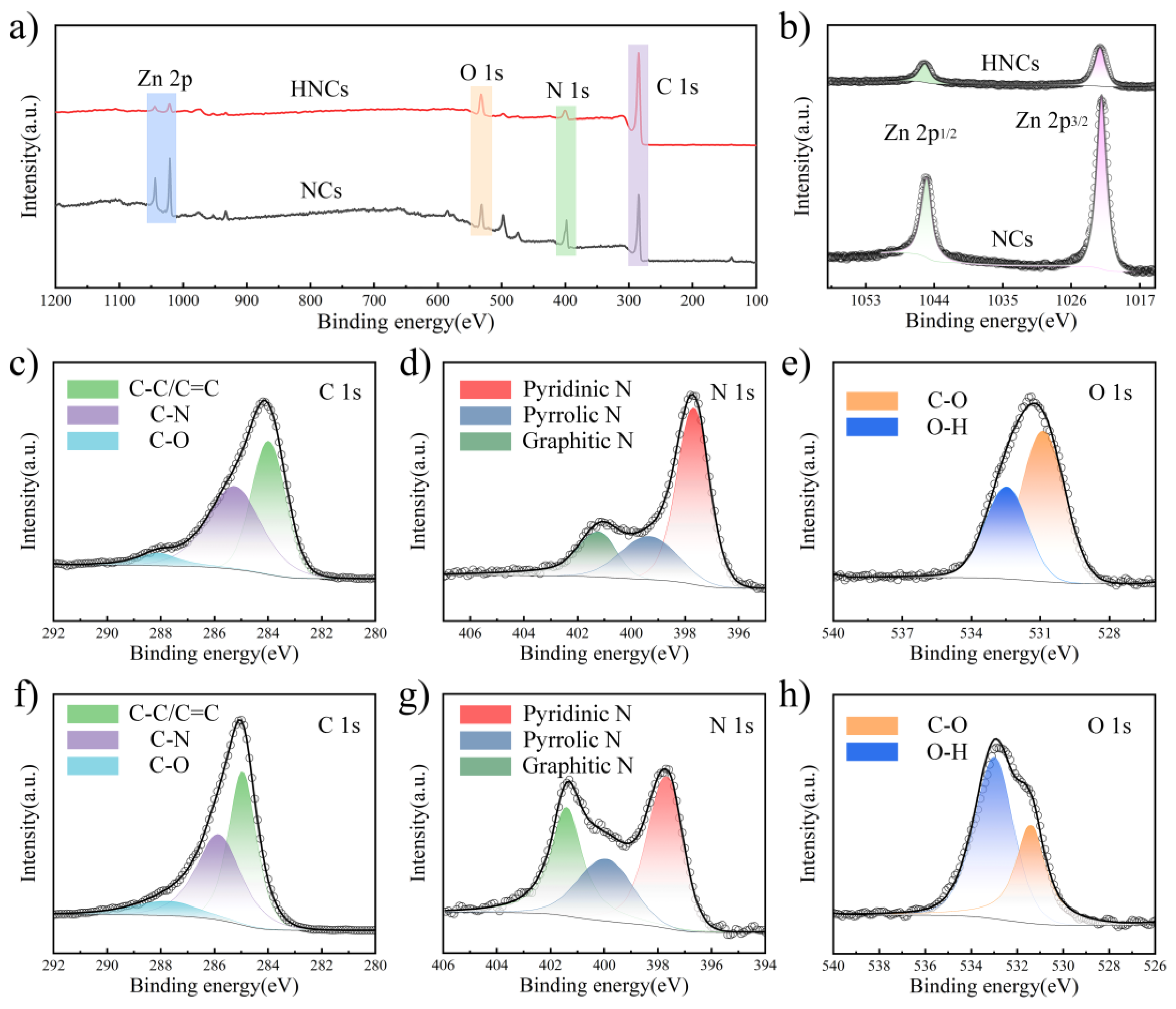
Figure 3.
(a,c,e) are SEM images of ZIF-8, ZIF-8-TA-1, and ZIF-8-TA-8 before carbonation. (b,d,f) are SEM images of ZIF-8, ZIF-8-TA-1, and ZIF-8-TA-8 after carbonation.
Figure 3.
(a,c,e) are SEM images of ZIF-8, ZIF-8-TA-1, and ZIF-8-TA-8 before carbonation. (b,d,f) are SEM images of ZIF-8, ZIF-8-TA-1, and ZIF-8-TA-8 after carbonation.
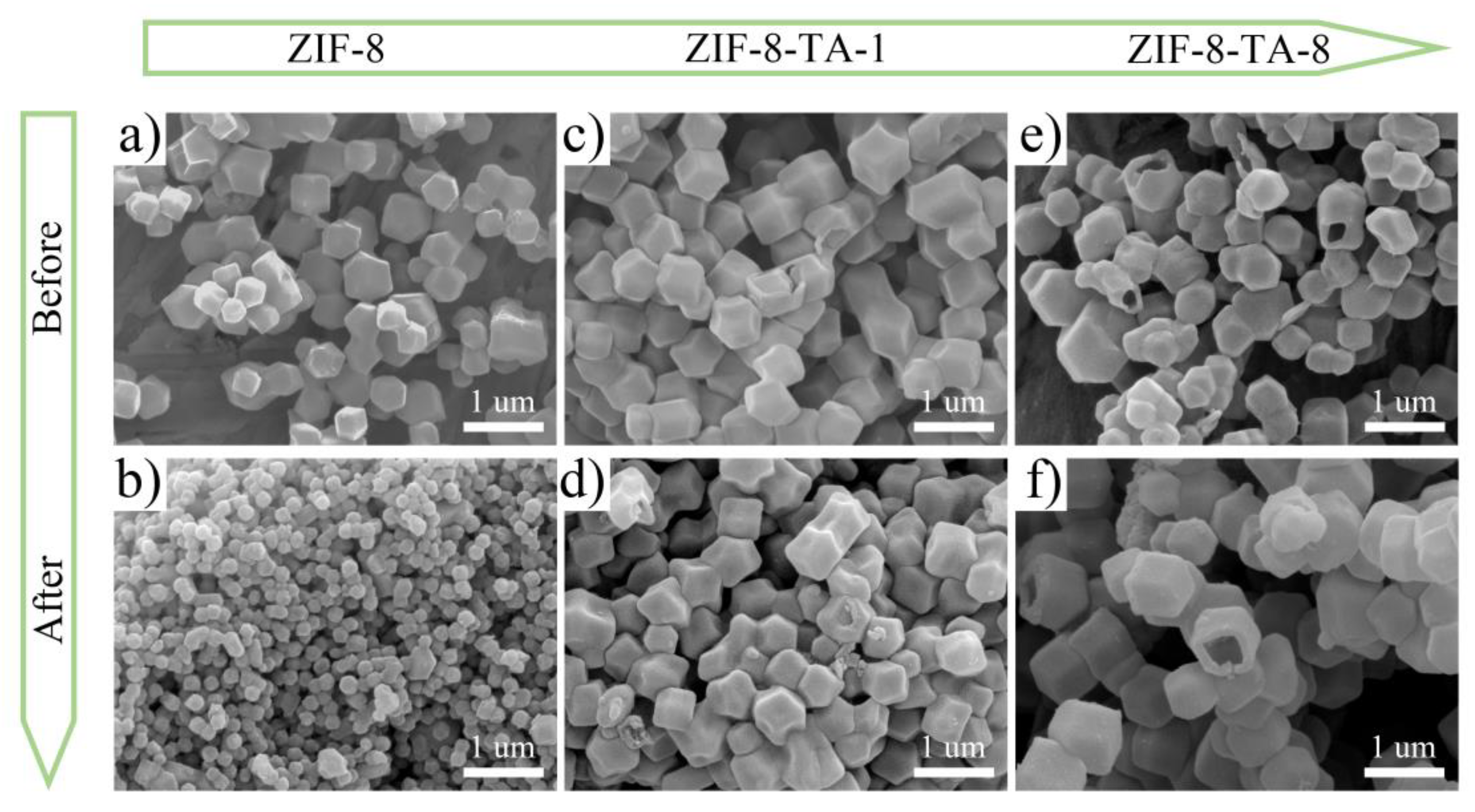
Figure 4.
(a–f) At different multiples TEM image of NCs, HNCs-1, HNCs-8.
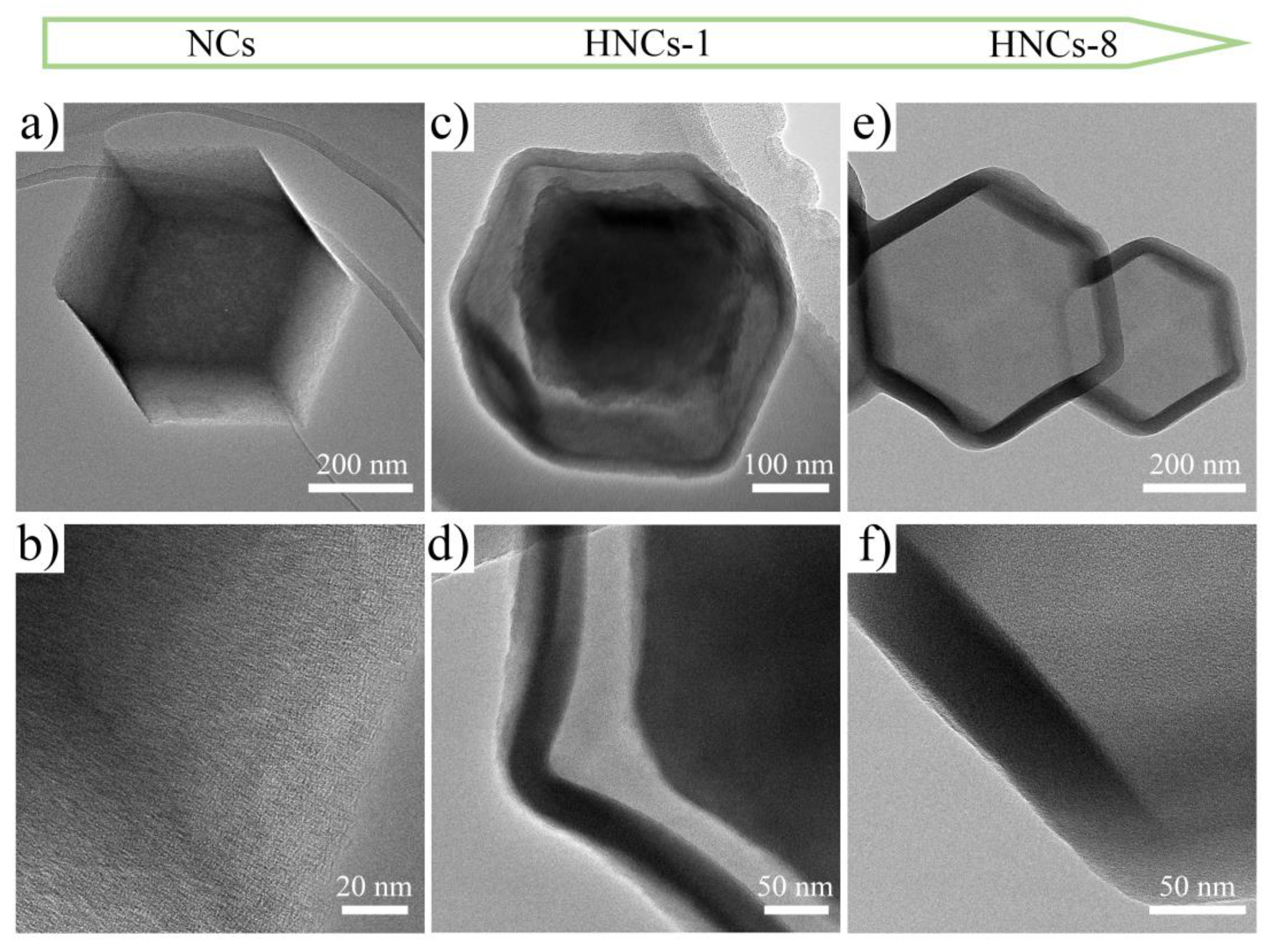
Figure 5.
(a) CV curves at various scan rates from 5-50 mV s−1 of HNCs-8. (b) GCD curves at different current densities from 0.5-5 A g-1 of HNCs-8. (c) The CV comparison diagram of different materials at different current densities. (d) The GCD comparison diagram of different materials at different current densities. (e) EIS comparison of different materials. (f) Comparison of specific capacity of different materials at different current densities. (g) Coulomb efficiency and capacity retention change diagram after 10, 000 cycles.
Disclaimer/Publisher’s Note: The statements, opinions and data contained in all publications are solely those of the individual author(s) and contributor(s) and not of MDPI and/or the editor(s). MDPI and/or the editor(s) disclaim responsibility for any injury to people or property resulting from any ideas, methods, instructions or products referred to in the content. |
© 2025 by the authors. Licensee MDPI, Basel, Switzerland. This article is an open access article distributed under the terms and conditions of the Creative Commons Attribution (CC BY) license (http://creativecommons.org/licenses/by/4.0/).
Copyright: This open access article is published under a Creative Commons CC BY 4.0 license, which permit the free download, distribution, and reuse, provided that the author and preprint are cited in any reuse.


