
Submitted:
02 April 2025
Posted:
03 April 2025
You are already at the latest version
Abstract
Concrete-filled steel columns are increasingly recognised for their enhanced structural performance. This study investigates an innovative shear connector design with screw connectors as an alternative to conventional connection types. From push-out testing, the shear capacity of screw connectors in composite columns comprising cold-formed steel sigma sections and concrete infill was evaluated. Experimental push-out testing demonstrated the effectiveness of theoretical equations in estimating the shear strength of screw connections. The comparison indicates that established design methods provide reasonable predictions, supporting their applicability in practical scenarios. Theoretical equations in the literature for estimating shear strength were tested for suitability and gave comparable results. De-assembling of tested specimens showed that a concrete failure was the prominent mode of ultimate condition. Shear screws offer a novel design alternative to conventional shear connection methods. They demonstrate significant potential for structural applications when integrated with advanced composite column sections, such as the four-sigma built-up CFS sections. The study highlights screw connectors as a cost-effective, sustainable, and practical solution for innovative composite column designs, offering significant potential for construction and maintenance efficiency.
Keywords:
Concrete-filled steel columns
; cold-formed steel sigma sections
; push-out analysis
; shear connectors
1. Introduction
Concrete-filled steel columns (CFSC) have become an effective alternative to traditional reinforced concrete and steel columns in modern construction. Their superior strength-to-weight ratio, enhanced load-bearing capacity, and improved buckling resistance make them a preferred choice for high-rise buildings and bridge construction [1]. This dual-material synergy has positioned CFSCs as a sustainable and cost-effective alternative to traditional single-material column systems [2]. Shear connectors play a critical role in these composite structures by ensuring the transfer of horizontal shear forces between the steel and concrete components, enabling composite action [3]. In addition, connectors are crucial in facilitating the assembly when utilising multiple cold-formed sections. Their presence ensures stability and load distribution, making them an integral part of the structural behaviour rather than mere fasteners. Therefore, assessing their co-existing function as connectors and components influencing shear capacity is essential for understanding their contribution to strength and efficiency. The demand for advanced structural designs has catalysed the exploration of innovative shear connectors, essential elements that facilitate the interaction between steel and concrete by transferring interface shear forces [4]. Without effective connectors, the composite action of CFSCs is compromised, leading to independent behaviour of the materials under load and reducing overall structural performance.
For decades, traditional shear connectors such as studs and bolts have dominated the design landscape. However, their limitations in adaptability, installation complexity, and maintenance challenges have prompted the search for alternatives. Although research on shear connectors has progressed significantly since the mid-20th century, most studies have focused on conventional connection types such as studs and bolts, limiting the applicability of existing theoretical models to innovative designs like screw connections [5]. Research on the effects of shear connections on composite columns dates to the 1950s [6]. Viest conducted the first test of shear connections in 1955, where push-out testing was used to determine shear strength [7]. The push-out test was deemed standard in the experimental investigation of shear connector strength. The test revealed that the shear connections failed in two main ways: concrete failure, where concrete surrounding the connection was crushed, causing connection deformation, and steel failure, where the connection reached its yield point and snapped/sheared in two. Based on such testing, it was the first mathematical model proposed for predicting the shear design strength of connections for either of these scenarios [7]. The equation was based on the effective depth of the shear connector and the strength of the concrete. In 1965, Driscol and Slutter proposed an alteration to Viest's equation in which the effective depth limits of connection were modified, and the area of steel was incorporated into the equation [8]. Ollgaard et al. furthered this investigation where a single equation independent of effective depth has been considered [9]. From this, the American Institute of Steel Construction (AISC) found these findings to be the basis for current standard equations. Since then, different international standards and independent researchers have implemented slight changes to numerical modelling to accurately estimate the shear strength of connections of various shapes and sizes.
Screw connectors, known for their ease of installation and versatility, have emerged as a promising option, particularly in novel cross-sectional designs such as sigma sections [10]. These sections, characterised by their unique geometry, offer enhanced buckling resistance and load distribution properties compared to conventional shapes like rectangular or circular columns. The combination of screw connectors with Sigma sections creates an opportunity to push the boundaries of CFSC applications while addressing critical gaps in existing research. Despite their potential, screw connectors remain underexplored in the context of CFSCs, especially for cold-formed steel sections. Cold-formed steel is favoured for its lightweight and high strength-to-weight ratio, but its thin walls pose challenges for traditional connection methods [12]. Screw connectors, with their self-tapping capabilities, mitigate these issues, providing a practical solution for assembling complex geometries [13].
Furthermore, the structural performance of screw connectors in unconventional cross-sections, such as the four-sigma section, remains underexplored. This study focuses on four sigma sections, an innovative arrangement of sigma profiles that maximises structural efficiency and simplifies construction processes. By investigating the shear capacity of screw connectors within this context, the research aims to provide experimental evidence and theoretical insights into their performance.
The methodology adopted in this study focuses on push-out testing, a standardised procedure for evaluating the shear capacity of connectors. The methods for constructing, testing, and analysing shear connections were established following international standards. AS 4600 [15] was utilised to define the requirements for the cold-formed sigma steel section, ensuring compliance with structural and shear screw properties. AS 2327 [12] provided guidelines for designing composite steel-concrete sections, influencing the construction of stub composite columns, shear connection setup, and push-out testing procedures. Additionally, EN 1994-1-1 [14] was referenced for standardised testing procedures, aligning with previous studies and enabling analytical estimation of composite column and shear connection properties. This method involves applying axial compression to the concrete core while restraining the steel section, allowing the measurement of interface slip and ultimate shear strength. The results are then analysed to identify failure modes, such as concrete crushing or screw shearing, and to assess the alignment of experimental findings with theoretical predictions. Key standards, including AS 2327 [12] and Eurocode 4 [14], offer a framework for these comparisons, although their applicability to screw connectors in cold-formed steel remains to be validated. This research contributes to the broader understanding of composite column behaviour, addressing critical gaps in the literature concerning non-traditional shear connectors and cold-formed steel applications. By providing empirical evidence and theoretical validation, the study sets the stage for future investigations into scaled-up specimens, long-term performance under cyclic loading, and the refinement of design standards to incorporate innovative connection types [26]. The findings advocate for the adoption of screw connectors in CFSCs to achieve enhanced structural performance, cost efficiency, and alignment with the evolving demands of modern construction.
2. Materials and Methods
This research investigates the shear capacity of screw connectors in composite columns comprising cold-formed steel sections with concrete infill, designed explicitly with a four-sigma channel cross-section. This cross-sectional configuration consists of channel-shaped members incorporating multiple folds or stiffeners along their width, optimising stiffness while minimising material consumption within the column [23,24]. The individual steel sections are interlocked and assembled to create a distinctive and structurally efficient column cross-section. The study aims to investigate the shearing resistance of screw connectors for the four-steel sigma section under axial compression. It also determines the shear failure of the screw connections for the four-steel sigma section under axial compression and the efficacy of the screw connections in such section through comparison of experimental and theoretical results. The ultimate shear strength of shear connections can be determined for a column section using an international standard test, the 'push-out' test [27,28,29,30,31,32].
2.1. Specimen Fabrication
The construction of testing specimens was planned in steps, with the design and construction techniques adapted from the previously mentioned standards and past studies [22,30,31]. The dimensions and specifications of the cross-section and shear connection details were adopted to develop a generalised approach to further testing with alternative cross-sections and connections, as in Figure 1 (a) and (b). All the dimensions and methods complied with the requirements specified in the previously referenced standards. A generalised method for specimen construction and testing preparation is explained in the following section.
Bending of steel sheets: Each specimen required four sigma-shaped sections as shown in Figure 1 (c). After finalizing the channel specifications, the steel sheets were sourced from JR Lasers Geelong. They were formed into the required sigma-shaped sections using a pan brake press, as illustrated in Figure 2. An industrial pan brake was used to bend sheets, allowing for variable bending angles. The pan brake had to be checked for adequacy in handling sheet thickness. A series of bends were made to form the channel section using the pan brake, and a digital angle gauge was used to achieve the required bending angles. Bends were checked using a protractor to ensure uniformity. All four sections had to be identical to interlock together and form the four-sigma configuration.
Assembling the steel component of the test specimen: Clamping methods depend on the shape of the section. Once four sigma sections were bent, they were combined in a clockwise overlapping pattern to form an interlocked pattern. A 'dry run' should be conducted first to ensure all pieces fit together and the general uniformity of the cross-section, Figure 3 (a). Once the desired cross-section has been formed, a series of clamps were used to hold the four channels to be combined using shear connections, Figure 3 (b). Screw connections were drilled using an impact driver as they are used to prevent slippage during construction Figure 3 (c). This process is the same for bolted, nailed, or any other insertable shear connection, although predrilling may be necessary. A foam insert was cut into the shape of the cross-section and inserted in the base of the specimen, Figure 3 (d). It is necessary to ensure that after the concrete is poured into the specimen and has undergone the curing process, the foam can be removed to create the base gap of the sample. It will ensure that during push-out testing, concrete has the space to be displaced under load.
Concrete pouring: The concrete infill was poured after assembling the steel sections and sealing all voids. The concrete mix design followed standard mix design procedures to achieve a compressive strength corresponding to M32. After mixing the concrete, a slump test was conducted to assess its workability, for which a slump value was 30 mm. Additionally, a set of plastic cylindrical moulds was prepared to evaluate the properties of the developed concrete mix following the designated curing period.
Standard tamping procedures were followed, pouring in at least three layers and tamping at least 25 times for each layer, as shown in Figure 4 (a). It was ensured that the concrete did not overflow the specimen and level with the top as shown in Figure 4 (b). The specimens were cured before testing for a standard curing period of 28 days. Once cured, the foam insert was removed, and the specimens were prepared for testing.
2.2. Test Setup
A generalised method for testing short column sections under push-out loading is employed in this study. Before testing, the equipment was configured following standard procedures. A UTM hydraulic jack is utilised to perform the push-out test, as illustrated in Figure 5. Depending on the specimen's cross-section, custom steel ridged collars were constructed and attached to the top and bottom of the specimen to hold them together and to avoid localised buckling. A uniform load distribution was ensured over the concrete section.
End-stiffening base plates were constructed, especially for thin-walled steel column sections like this. There is no standard method for its implementation, so high-strength steel sections were welded to steel specimens to prevent the movement of steel sections and allow for the push-out of concrete vertically and smoothly. Depending on the hydraulic press, UTM was able to measure displacement independently.
2.3. Test Instrumentation
In the testing, two laser displacement sensors were placed above the concrete section to measure the displacement as during the application of the load. The setup was planned so that the relative movement of steel and concrete could be found. The lasers were so placed that one end is fixed to an immovable beam (representing the steel built-up section) while the laser tip is on the concrete from the top, perpendicular to the concrete. Synchronising this laser to the relative motion will give accurate results of the infill movement by correlating to the load measurement. Figure 6 depicts the positioning of the lasers at two different points on the top end of the specimen, only on the concrete.
2.4. Test Procedure
Push-out testing was conducted once the specimen was secured to the hydraulic press and steel sections were made immovable. Displacement control is generally adapted as 0.5 mm/min to capture buckling accurately until failure mode AS 2327 states that for testing, the load shall be applied in increments up to 40 percent of the expected failure load and then cycled at least 25 times between 5 percent and 40 percent of the predicted failure load. Subsequent load increments were imposed so that failure did not occur in less than 15 minutes. Loading continued post-failure until the concrete core was pushed through the entire gap (50 mm) and reached the base plate. Load-slip data was then recorded and tabulated based on the experimental results.
The data collected from experimental testing was assessed by constructing a load-slip graph and analysis was done. Analysis of the load-slip curve includes the staging of slip, elastic stage, inelastic stage, and past failure. Due to 3 specimens being tested, three load-slip curves were generated and compared. Depending on the failure case, the failure stage of the graph may exhibit different properties. This data collection shows that the ultimate shear strength is the most critical factor of this research. Video footage of the testing was taken to observe the deterioration of specimens over time and help determine when failure initially occurs.
3. Results and Discussion
3.1. Concrete Cylinder Testing
A total of 9 concrete cylinders were tested: 3 for compressive strength (C:1-3), 3 for tensile strength (T:1- 3), and 3 for modulus of elasticity (E:1- 3). Based on testing and the concrete cylinder parameters, the average compressive strength, tensile strength, and modulus of elasticity have been outlined in Table 1. Figure 7 shows a collective image of the three different material tests conducted.
3.2. Push-Out Specimen Testing
Three push-out specimens were tested, of which displacement data was collected from 2 laser sensors. The specimens are denoted as 4S-C1, 4S-C2, and 4S-C3, meaning that four sigma channel sections (4S) were used to form the steel specimen, and the infill used is concrete (C). The push-out analysis recorded an ultimate shear strength for 4S-C1 of 70.961 kN. The ultimate shear strength was observed after the concrete had been displaced an average of 4.69 mm over the two laser sensors. Laser one was disconnected from the specimen in the push-out testing of 4S-C2; hence, its data was disregarded. An ultimate shear strength for 4S-C2 of 74.808 kN was recorded. The ultimate shear strength was observed after the concrete had been displaced an average of 5.843 mm over a single laser sensor. An ultimate shear strength for 4S-C3 of 71.2551 kN was recorded. The ultimate shear strength was observed after the concrete had been displaced an average of 4.58 mm over the two laser sensors.
Table 2 shows the shear strength and shear strength per screw connection for three specimens, where the effectiveness and consistency of the screw connections in transferring shear loads within composite columns are demonstrated. Shear strength per screw connection between the tested samples ranged between 8.87 kN and 9.35 kN, averaging 9.04 kN. The test results indicated consistent performance by all the samples; hence, this is reliable as far as using screws for carrying loads is concerned. The total shear strength of the specimens is 70.96 kN, 74.81 kN, and 71.23 kN, which all lie in the narrow range, and the average is 72.33 kN. It, in turn, reflects the consistent behaviour and reliable load distribution across all the screw connections. The agreement between the experimental and theoretical values, as given later in the table 5, should be within 10%, validating that the self-tapping screw connections indeed deliver performance comparable to that of conventional shear connections such as studs or bolts. The average shear strength per screw (9.04 kN) shows the possibility of utilising screw connectors for composite column design as a more economical and effective solution. It indicates that such connections can fulfil real-world engineering conditions. The obtained results confirm that screw connections may be used safely and reliably with consistent shear load transfer, opening up the door to cost advantages, ease of installation, and adaptability.
The load-displacement curves from all three specimens are presented in Figure 8. Every curve corresponds to the composite columns' shear strength and displacement behaviour, with ultimate variations in strength and displacement. For all specimens, the laser readings (:1 and :2) showed identical results, indicating a balanced distribution of load and accurate measurement. 4S-C2 displayed the highest ultimate shear strength at 74.81 kN, with a displacement of 5.843 mm. Due to a malfunction in the laser sensor, only one laser sensor's data was used for some specimens, and slight variability in displacement accuracy could have been introduced. Specimens 4S-C1 and 4S-C3 reflected similar response patterns with ultimate shear strength, with the average displacement measured from two sensors being 4.58 mm. The combined load-displacement curves help illuminate the structural performance consistency among the three specimens, along with the ultimate shear strength with a narrow range. The curves also indicate the typical response of composite columns to screw connections, from initial stiffness and peak load capacity to post-peak behaviour. Results ultimately emphasise the trustworthiness of screw connectors in transferring shear forces in composite columns.
The data shows post failure for two specimens (4S-C1 and 4S-C3), a rapid decline in load-bearing capacity with a gradual increase in displacement showing a particularly sudden failure. However, 4S-C2 had an elongated curve around failure and a less gradual failure. It also exceeded other specimens' shear strength by over 3 kN. All specimens experienced a similar initial slip at around 20-23 kN. This initial slip coincides with the load required for debonding steel and concrete surface resistance. At this load, the shear connections begin to undergo loading and experience elastic deformation as the load increases. Again, all specimens also experienced a very similar yield point of around 47-50kN. This yield point denotes the end of the linear section of the load-displacement curves and indicates the beginning of plastic deformation of the connections. All load-displacement curves further support the assessment of concrete crushing as the prominent failure mode. It can be evidenced by the final stage of the curve, the post-yielding stage past failure. It means rather than a gradual post-yielding stage, failure is sudden.
Table 3 summarises the experimental measurements of three tested specimens as a function of the shear load and displacement stage. The key parameters are the slip at the interface, yield slip, shear strength slip, and end slip with the corresponding loads. Interface slip values are closely banded, averaging 0.197 mm, meaning that the slips at the interface were spread uniformly at all steps of early loading. Interfacial loads averaged 21.945 kN, which was transferred stably throughout the specimens. The yielding slip averaged 1.155 mm, and the yielding strength averaged 48.442 kN. These parameters reflect the columns' elastic limit and resistance to significant loads before yielding. The shear strength slip averaged 4.876 mm, indicating uniform deformation before peak strength. The average ultimate shear strength was 71.336 kN, indicating consistent and robust shear strength across specimens. The end slip averaged 17.607 mm, with an average end load of 33.259 kN. This stage is the residual capacity after failure. The table also shows that screw connectors are quite reliable and consistent in transferring shear loads within composite columns and thus validate the structural performance of the connectors.
3.3. Failure Modes
It is necessary to determine a prominent mode of failure based on the observation of specimen testing. The screw notations were previously shown in Figure 1. Of all three specimens tested, concrete crushing was identified as the prominent failure mode, as the crushing of the concrete surrounding the screw shank allowed for screw bending. This failure could be categorised as either brittle shear failure, resulting in a cut-off of the screw, or ductile failure, where the screw is bent due to the high local stresses induced by the surrounding concrete crushing. No evidence of screw head shearing was observed post-testing, further supporting concrete crushing as the primary mode.
Due to the cross-sectional format, the concrete was not visible from the exterior after testing. Therefore, the specimens were deconstructed to evaluate any internal damage. In cases where shear screws could not be removed due to deformation, the specimen was cut open. The deformation of the steel shearing screws, if present, was examined and documented as part of the failure analysis, along with any buckling of the steel sheet or crushed concrete. A final assessment was made to determine the primary failure mode of the specimen, categorising it as either concrete crushing or shear screw failure. Although multiple failure modes could have been observed, the most prominent mode was identified. A theoretical equation was used to assist in determining the type of failure. As illustrated in Figure 9 (a), intact screw heads with the connection body suggested concrete crushing, as no shearing failure occurred. Conversely, Figure 9 (b) shows bulging of the steel sheet along the screw path, further indicating concrete crushing.
In Figure 10, concrete crushing is the clear, prominent mode of failure for seven out of the eight screws. It should be noted that screw heads were cut off in the deconstruction process, not because of shearing during testing. Localised concrete crushing occurs in the direct path of the screw as it deforms under push-out testing. Concrete crushing around the fasteners was the prominent failure mode for all specimens based on deconstruction and exterior observation.
In Figure 11 (a), the screw head is sheared off, focusing attention on the force distribution and the surface damage caused. At this stage, stress concentrations on the screw head significantly determine how the shear resistance of the screw will be expected to perform. In Figure 11 (b), the shearing of the screw tells that the applied load exceeded the screw shear strength. Such a failure mode represents the intrinsic limitability of screw connectors during high shear forces, which will probably depend on the strength of steel, penetration depth, and loading distribution among the screws. Failure in Figure 11 (c) by concrete crushing reveals failure where the strength of concrete infill cannot resist the shear forces applied to it, especially near screw connections. Concrete compaction, material homogeneity, and void presence are significant factors in this failure mode [20]. These failure modes highlight the interaction between screw connectors and concrete infill, thus underlining the need to optimise connector design, material properties, and construction techniques to enhance the shear performance of composite columns.
It was noted from the results of this study that concrete crushing was the prominent failure mode, shear connections remained intact and hence held on to the concrete, causing a more extended post-yielding stage. Steel and concrete materials are entirely disconnected if shearing were the prominent failure mode (as they have already been chemically debonded); hence, no additional load is required to induce further displacement [19]. A more significant load is necessary to continue displacement post-failure when concrete crushing occurs. It was found that for this shear connection configuration, experimental data presented an average ultimate shear strength of 9.041 kN. AS 2327 [12] states that where three tests on nominally identical specimens are conducted, and results from any individual test do not exceed the mean by more than 10%, results may be considered for further statistical analysis. The difference between the average ultimate shear strength and the most significant difference in individual shear strength was less than 10% (~3% difference). The results of the observation of screw failure from deconstructed specimen have been presented in Table 4. This table should be read in conjunction with Figure 1 for notation of screw ID.
4. Mathematical Representation
Theoretical results based on the relevant standards utilised across and from other pertinent references were calculated below. They have been compared to the experimental average ultimate shear strength of 9.041 kN. Theoretical equations have been ranked 1 - 6 in order of their proximity to experimental results. Table 5 lists equation factors to analyse a trend relating to comparing results. If a term is included in the equation, it has been denoted with an 'X'. Their percentage difference has also been calculated in Table 5.
It was found that the oldest expression, initially outlined by Viest in 1956 [7], was the closest to the experimental results. It recorded a difference of only 0.29% compared to that of the least accurate equation for this study proposed by Slutter and Driscoll, with a difference of 23.15% depending on the theoretical equation used. A variation in theoretical shear strength was calculated [8]. Due to the variance in results across international standards and research articles, from over-design to under-design, further research is required to express theoretical results more accurately. Theoretical results obtained via the Eurocode 4 [23] bore an under-design of 22.82%, whereas Slutter and Driscoll's method gave an over-design of 23.15% in shear strength. A trend relating to the accuracy of results and including mathematical terms could not be developed. On average, equations derived from Ollgaard's model (all international standards) translated to more accurate results than Viest's original equation [7]. These equations have one main thing in common compared to other equations: they derive their results from the connection area rather than the penetration depth.
All these equations rely heavily on the coefficients derived relating to the area of connection. AS 2327 has a connection area coefficient of 0.5, whereas GB50017 has a coefficient of 0.43. Other than this coefficient, the equations are identical. By just the difference in this coefficient, AS 2327 and GB50017 have a difference in experimental results of 9.30% and 5.47%, respectively. This coefficient holds significant weight in these models. Results indicate that there should be a reconsideration for this coefficient depending on the connection type (screw, bolt, stud, etc.) or the implementation of a variable that more accurately reflects experimental results. Viest's equation, although the most accurate in this instance, is outdated and extremely limited in its use cases as it has multiple coefficients based on limited testing at the time [7]. However, the theoretical results obtained through current standards, AS 2327, show that screw connectors under analysis acted within reasonable bounds (within 10%) of that of a traditional shear connection (such as stud or bolt) [13]. Investigation into load-displacement curves shows critical properties, and the three stages, elastic, yielding, and post-yielding stages, indicate traditional shear connections under axial compression.
5. Conclusions and Recommendations for Future Research
This study investigated the shear strength and failure mechanisms of screw connectors in four-steel sigma section composite columns using axial compression push-out testing. The experimental results were analysed and compared to theoretical models outlined in AS 2327 [12], providing insights into the structural behaviour of screw connections. The following key conclusions were drawn:
- The screw connectors exhibited an average shear strength of 9.041 kN per screw, as determined through axial compression push-out tests. Observations of the tests and specimen deconstruction revealed that the dominant failure mode was concrete crushing at the connection points.
- Experimental and theoretical comparisons showed that screw connectors performed within 10% of traditional shear connections, such as studs or bolts, as defined by AS 2327 [12]. However, the assumption of homogeneous concrete and uniform load distribution may have influenced the per-screw shear resistance values.
- Only three specimens were tested due to the scope of the study, and while all results fell within 10% of the mean, a larger sample size would provide a more accurate mean shear strength. The assumption of concrete homogeneity across the specimens could have affected the failure mode assessment, potentially exaggerating the concrete crushing failure mode.
- The study highlights the potential of self-tapping screw connections as a viable alternative to traditional shear connections in composite columns. Multi-sectional steel sections, such as the four-steel sigma section, can improve transport, construction, maintenance, and deconstruction phases. This innovative design presents a cost-effective, time-efficient, safe, and sustainable alternative to traditional composite columns.
Further research is necessary to refine the understanding of screw connectors in composite columns. Single connection testing should be conducted to address the influence of load distribution assumptions. Additionally, larger sample sizes should be tested to enhance statistical reliability. Advanced concrete compaction techniques like vibration should be considered to mitigate the effects of voids on failure modes. The development of a more precise mathematical model for screw connection shear strength beyond AS 2327 is essential. Future studies should incorporate Finite Element Modelling (FEM) and statistical analysis to examine the effects of different concrete properties, connection parameters (such as screw penetration depth and steel strength), and external loading conditions (including seismic and fatigue loading).
Author Contributions
Conceptualization, S.S.S., B.K. and R.A.-A.; methodology, S.S.S., B.K. and R.A.-A.; validation, S.S.S., B.K. and R.A.-A.; formal analysis, S.S.S.; writing—original draft preparation, S.S.S.; writing—review and editing, B.K. and R.A.-A.; visualization, S.S.S.; supervision, R.A.-A. and B.K.; project administration, R.A.-A. All authors have read and agreed to the published version of the manuscript.
Funding
This research received no external funding.
Data Availability Statement
Not applicable.
Conflicts of Interest
The authors declare no conflicts of interest.
References
- He, S.; Fang, Z.; Mosallam, A.S.; Ouyang, Y.; Zou, C. Behavior of CFSC-encased shear connectors in steel-concrete joints: Push-out tests. J. Struct. Eng. 2020, 146, 04020015. [Google Scholar] [CrossRef]
- Papavasileiou, G.S.; Charmpis, D.C.; Lagaros, N.D. Optimised seismic retrofit of steel-concrete composite buildings. Eng. Struct. 2020, 213, 110573. [Google Scholar] [CrossRef]
- Shariati, M.; Sulong, N.R.; Shariati, A.; Kueh, A.B.H. Comparative performance of channel and angle shear connectors in high strength concrete composites: An experimental study. Constr. Build. Mater. 2016, 120, 382–392. [Google Scholar] [CrossRef]
- Colajanni, P.; La Mendola, L.; Latour, M.; Monaco, A.; Rizzano, G. Analytical prediction of the shear connection capacity in composite steel–concrete trussed beams. Mater. Struct. 2017, 50, 1–18. [Google Scholar] [CrossRef]
- Jelčić Rukavina, M.; Skejić, D.; Kralj, A.; Ščapec, T.; Milovanović, B. Development of lightweight steel framed construction systems for nearly-zero energy buildings. Buildings 2022, 12, 929. [Google Scholar] [CrossRef]
- Chen, Y.; Tong, J.; Li, Q.; Xu, S.; Shen, L. Application of High-Performance Cementitious Composites in Steel-Concrete Composite Bridge Deck Systems: A Review. J. Intell. Constr. 2024, 2, 1–23. [Google Scholar] [CrossRef]
- Viest, I.M. Investigation of stud shear connector for composite concrete and steel T-beam. ACI Journal 1956, 27. [Google Scholar]
- Slutter, R.G.; Driscoll Jr, G.C. Flexural strength of steel-concrete composite beams. J. Struct. Div. 1965, 91, 71–99. [Google Scholar] [CrossRef]
- Ollgaard, J.G.; Slutter, R.G.; Fisher, J.W. Shear strength of stud connectors in lightweight and normal-weight concrete. Eng. J. 1971, 8, 55–64. [Google Scholar] [CrossRef]
- Hussein, A.B.; Papp, F. State-of-the-Art: Integrating Fastener Technology and Design Guidelines for Enhanced Performance of Cold-Formed Steel Sections. Buildings 2023, 13, 2338. [Google Scholar] [CrossRef]
- De'nan, F.; Yeou, C.Y.; Salim, W.S.W.; Rahman, N.A.; Hashim, N.S. Assessing Cold-Formed Steel Section Performance in Fire: A Comprehensive Review of Numerical Models and Resistance Factors. International Journal of Steel Structures 2024, 1–19. [Google Scholar] [CrossRef]
- AS/NZS 2327: 2017; Composite Structures-Composite Steel-Concrete Construction in Buildings. 2017.
- Australian Standards (AS 2327); Composite structures - Composite steel-concrete construction in buildings. Standards Australia, 2019; p. 2019.
- Eurocode 4 (EN 1994-1-1); Design of composite steel concrete structures. CEN, 2005.
- AS/NZS 4600:2018; Australian Standards. Cold-formed steel structures. 2018.
- AISC 2005; ANSI/AISC 360-05 specification for structural steel buildings. American Institute of Steel Construction. 2005.
- GB50017-2003; Code for design of steel structure. China Planning Press, National Standards of People’s Republic of China, 2003.
- Pallarés, L.; Hajjar, J.F. Headed steel stud anchors in composite structures, Part I: Shear. J. Constr. Steel Res. 2009. [Google Scholar] [CrossRef]
- Lu, B.; Zhai, C.; Li, S.; Wen, W. Predicting ultimate shear capacities of shear connectors under monotonic and cyclic loadings. Thin-Walled Struct. 2019, 141, 47–61. [Google Scholar] [CrossRef]
- Shen, M.H.; Chung, K.F.; Elghazouli, A.Y.; Tong, J.Z. Structural behaviour of stud shear connections in composite floors with various connector arrangements and profiled deck configurations. Eng. Struct. 2020, 210, 110370. [Google Scholar] [CrossRef]
- Maleki, S.; Bagheri, S. Behavior of channel shear connectors, Part I: Experimental study. J. Constr. Steel Res. 2008, 64, 1333–1340. [Google Scholar] [CrossRef]
- Rahnavard, R.; Craveiro, H.D.; Lopes, M.; Simões, R.A.; Laím, L.; Rebelo, C. Concrete-filled cold-formed steel (CF-CFS) built-up columns under compression: Test and design. Thin-Walled Struct. 2022, 179, 109603. [Google Scholar] [CrossRef]
- EN 1994-1-1:2004; Eurocode 4: Design of Composite Steel and Concrete Structures, Part 1-1: General Rules and Rules for Buildings. European Committee for Standardization (CEN): Brussels, Belgium, 2004.
- Oeztuerk, F.; Mojtabaei, S.M.; Şentürk, M.; Pul, S.; Hajirasouliha, I. Buckling behaviour of cold-formed steel sigma and lipped channel beam–column members. Thin-Walled Struct. 2022, 173, 108963. [Google Scholar] [CrossRef]
- Antony, A.G. Study on cold formed steel sigma sections and the effect of stiffeners. Int. J. Innov. Res. Sci. Eng. Technol. 2016, 5, 16249–16255. [Google Scholar]
- AS/NZS 2327:2017; Australian Standards. Composite structures –Composite steel-concrete construction in buildings. 2017.
- Roy, K.; Ting, T.C.H.; Lau, H.H.; Lim, J.B. Experimental and numerical investigations on the axial capacity of cold-formed steel built-up box sections. J. Constr. Steel Res. 2019, 160, 411–427. [Google Scholar] [CrossRef]
- Zheng, S.; Zhao, C.; Liu, Y. Analytical model for load–slip relationship of perfobond shear connector based on push-out test. Materials 2018, 12, 29. [Google Scholar] [CrossRef] [PubMed]
- Dos Santos, L.R.; Caldas, R.B.; Prates, J.A.; Rodrigues, F.C.; de Sousa Cardoso, H. Design procedure to bearing concrete failure in composite cold-formed steel columns with riveted bolt shear connectors. Eng. Struct. 2022, 256, 114003. [Google Scholar] [CrossRef]
- Teoh, K.B.; Chua, Y.S.; Dai Pang, S.; Kong, S.Y. Experimental investigation of lightweight aggregate concrete-filled cold-formed built-up box section (CFBBS) stub columns under axial compression. Eng. Struct. 2023, 279, 115630. [Google Scholar] [CrossRef]
- Rahnavard, R.; Craveiro, H.D.; Simões, R.A.; Laím, L.; Santiago, A. Buckling resistance of concrete-filled cold-formed steel (CF-CFS) built-up short columns under compression. Thin-Walled Struct. 2022, 170, 108638. [Google Scholar] [CrossRef]
- Dos Santos, L.R.; de Sousa Cardoso, H.; Caldas, R.B.; Grilo, L.F. Finite element model for bolted shear connectors in concrete-filled steel tubular columns. Eng. Struct. 2020, 203, 109863. [Google Scholar] [CrossRef]
- Eghbali, N.B.; Andamnejad, P. Structural performance of rigid shear connectors in concrete encased steel composite columns. Structures 2023, 54, 348–368. [Google Scholar] [CrossRef]
Figure 1.
(a) and (b) Sigma channel section and (c) Specimen cross-section.
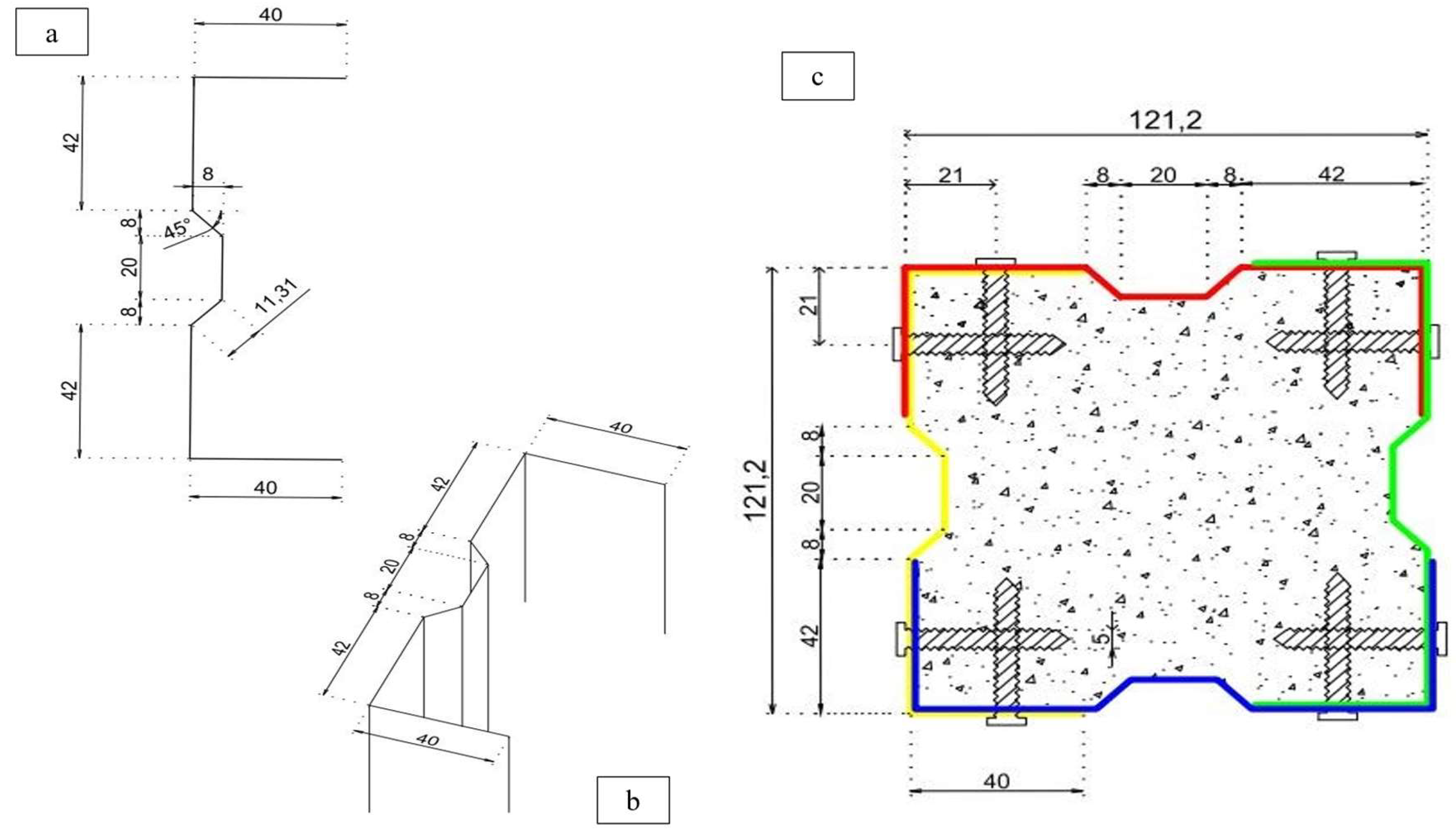
Figure 2.
Sigma Section Bending Process.
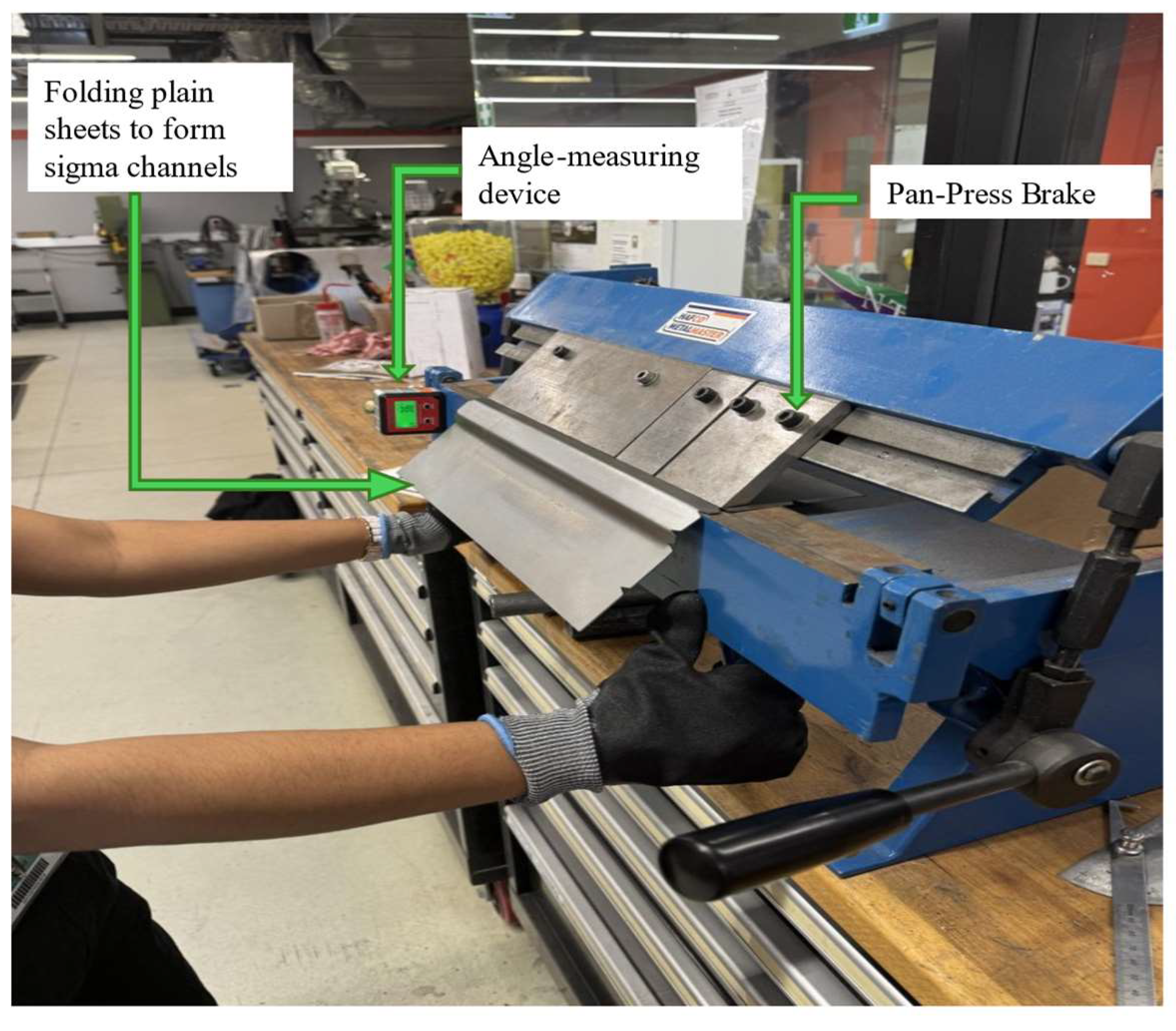
Figure 3.
(a) and (b) Specimen before shear screw insertion (c) and (d) Specimen post shear screw insertion.
Figure 3.
(a) and (b) Specimen before shear screw insertion (c) and (d) Specimen post shear screw insertion.
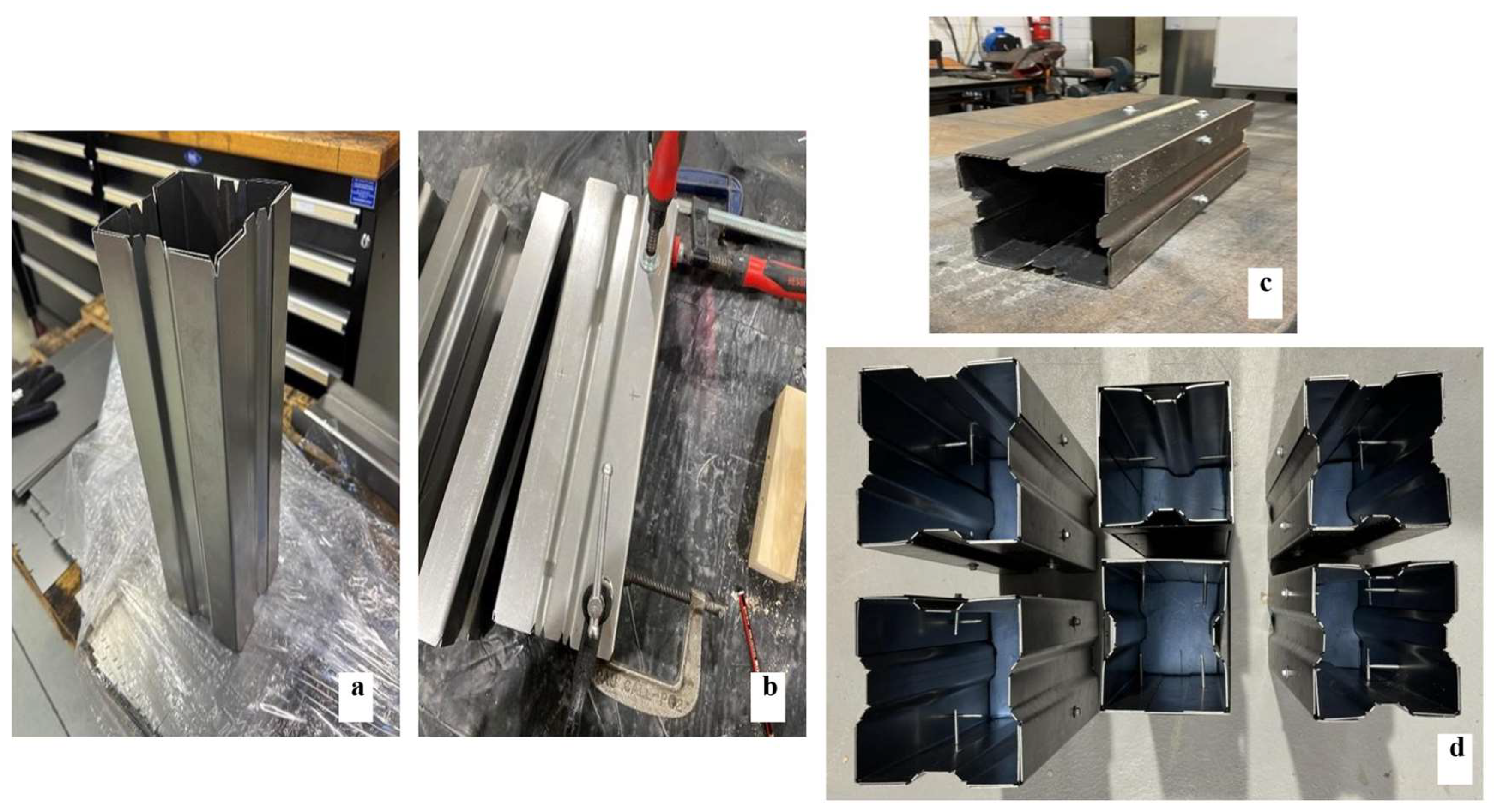
Figure 4.
(a) Tamping of concrete to specimen (b) Specimens post concrete pour.
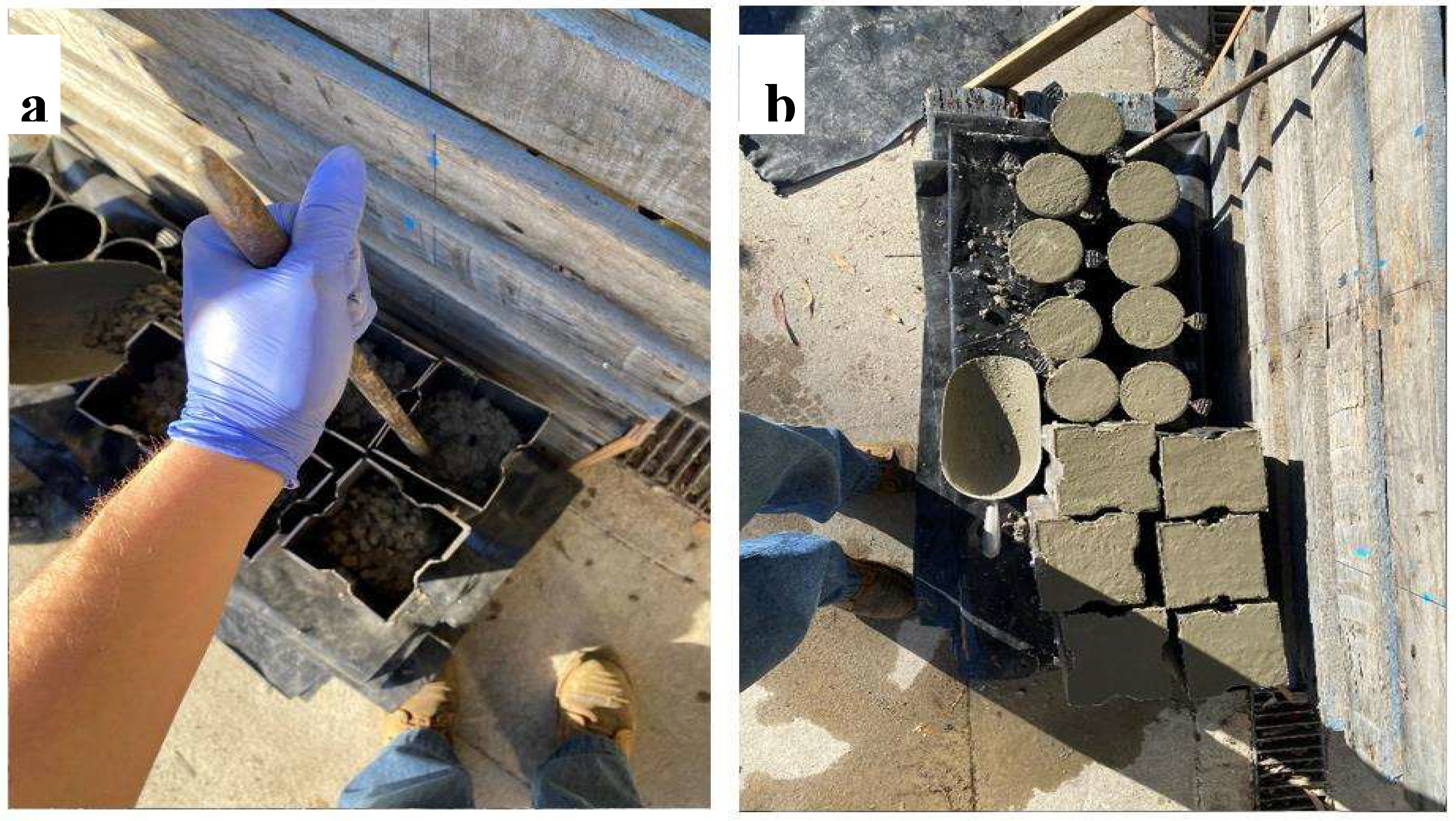
Figure 5.
Experimental Setup.
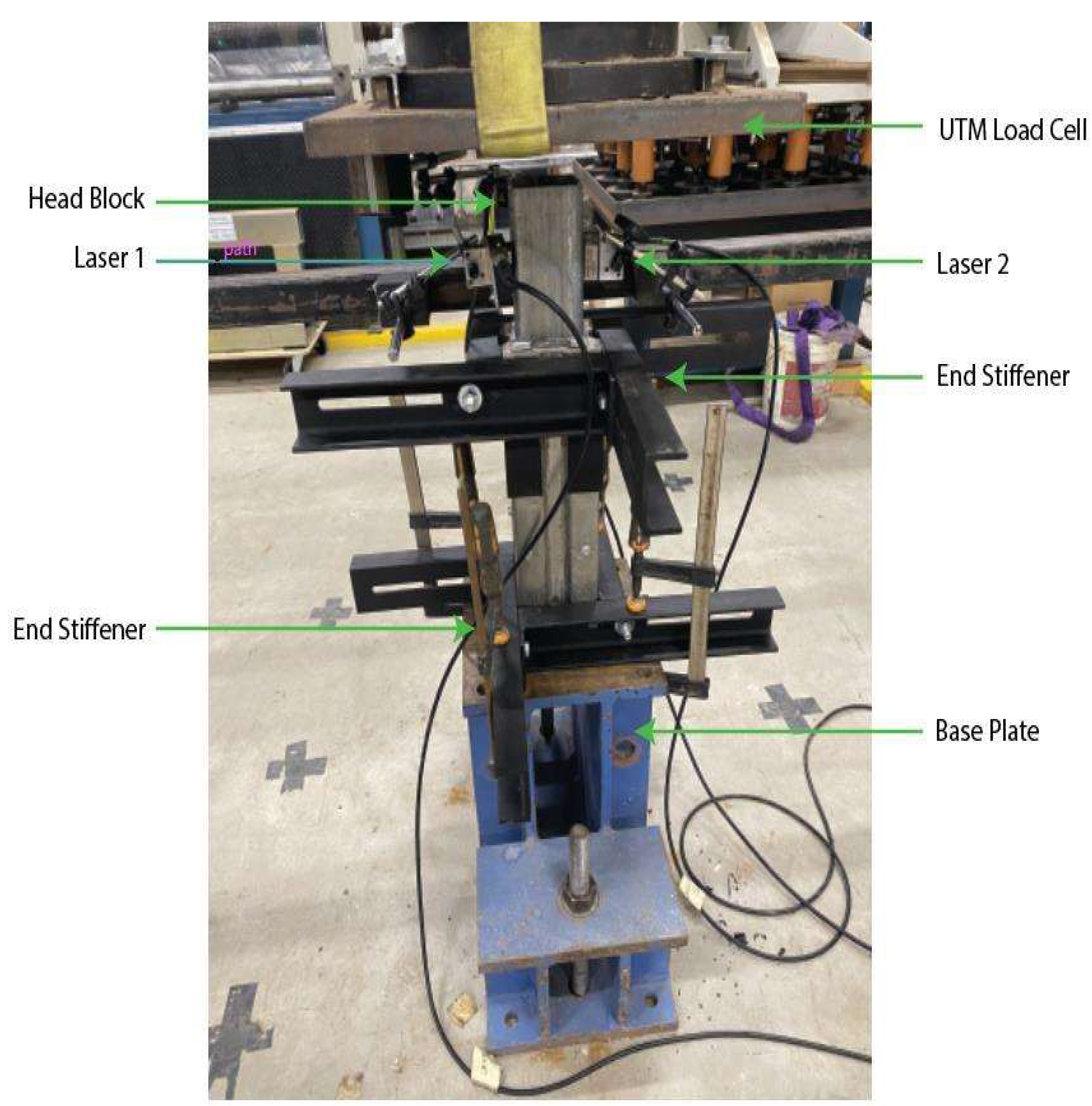
Figure 6.
(a) Specimen's instrumentation setup, (b) two lasers for recording absolute slip reading, and (c) laser positions.
Figure 6.
(a) Specimen's instrumentation setup, (b) two lasers for recording absolute slip reading, and (c) laser positions.
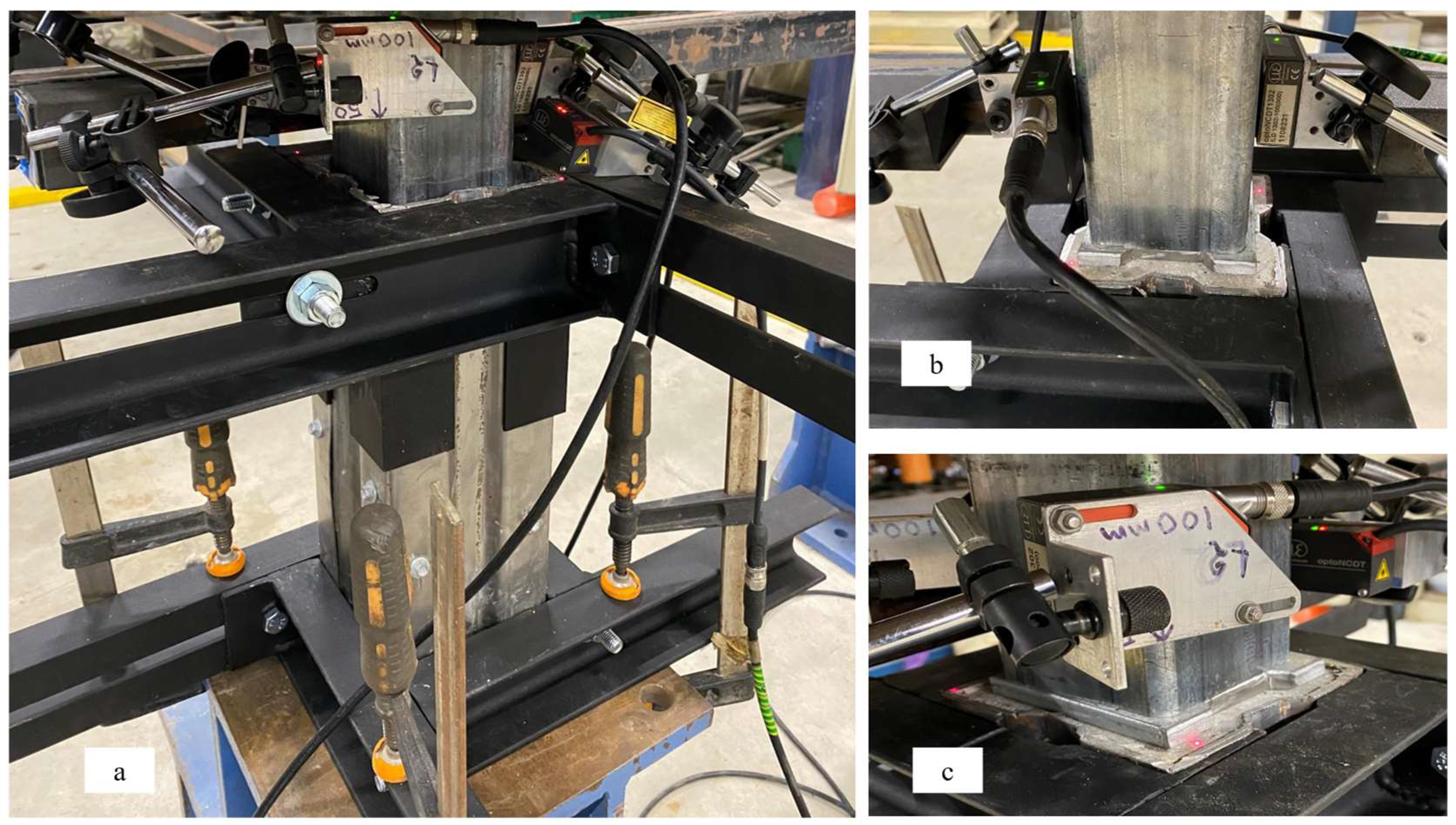
Figure 7.
Specimens after testing of (a) Compressive Strength, (b) Tensile Strength, and (c) Modulus of Elasticity.
Figure 7.
Specimens after testing of (a) Compressive Strength, (b) Tensile Strength, and (c) Modulus of Elasticity.
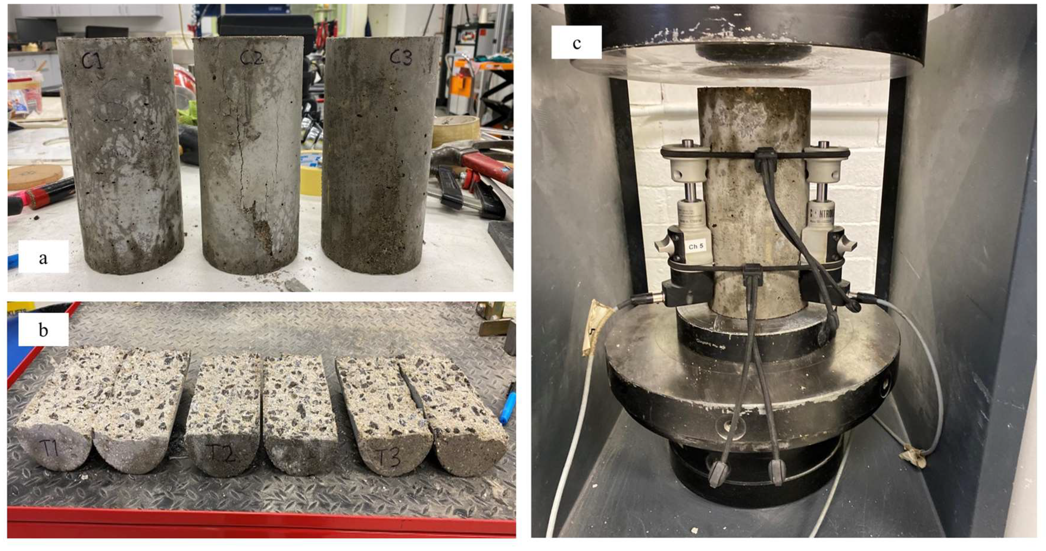
Figure 8.
Combined Load- Displacement Curve.
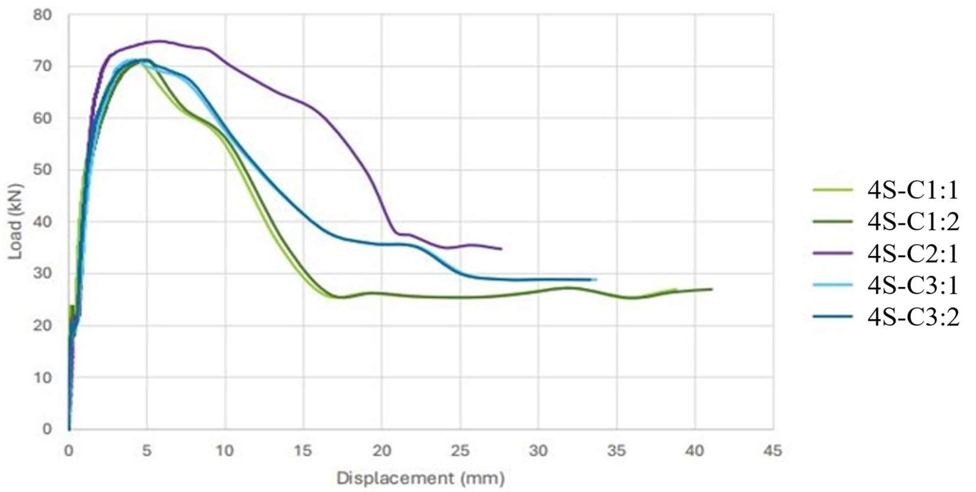
Figure 9.
Specimen before deconstruction (a) Screw heads remaining intact (b) Bulging of steel sheet.
Figure 9.
Specimen before deconstruction (a) Screw heads remaining intact (b) Bulging of steel sheet.
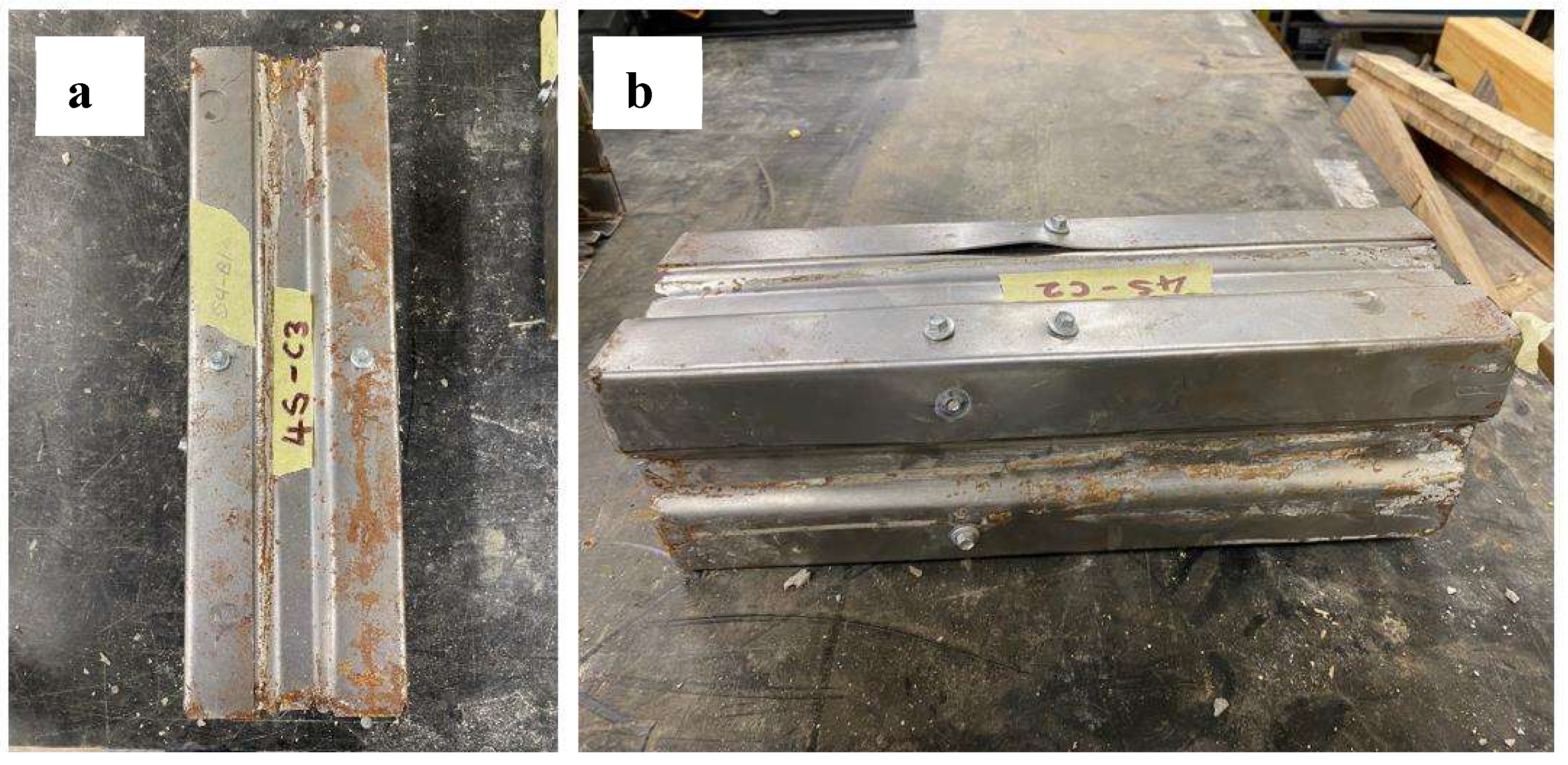
Figure 10.
(a) screw head during testing (b) screw shearing failure (c) failure via concrete crushing.
Figure 10.
(a) screw head during testing (b) screw shearing failure (c) failure via concrete crushing.
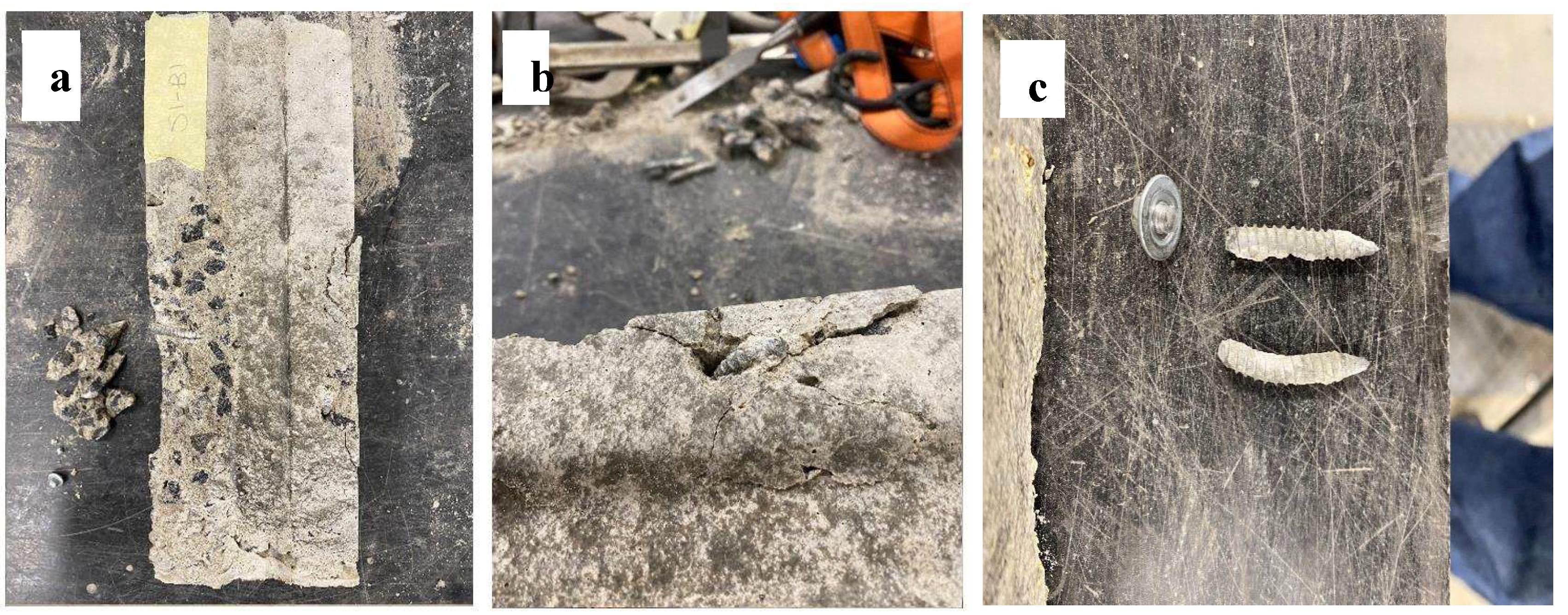
Figure 11.
Screw failure (a) ductile bending with crushing of concrete around (b) screw head shearing with moderate cracks (c) bending of screw inside the concrete without much crushing.
Figure 11.
Screw failure (a) ductile bending with crushing of concrete around (b) screw head shearing with moderate cracks (c) bending of screw inside the concrete without much crushing.
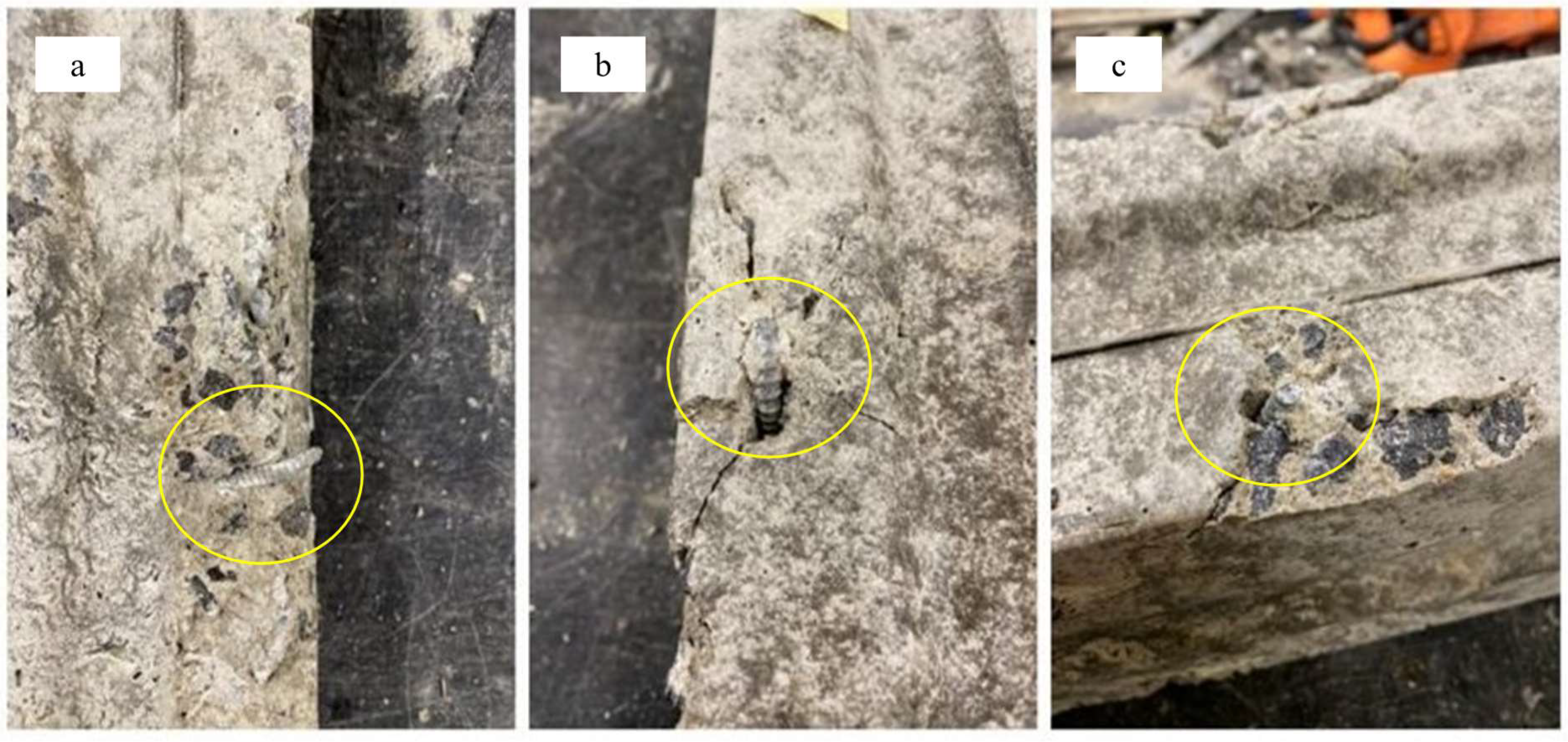

Table 1.
Concrete cylinder properties.
| Properties | Value (MPa) |
|---|---|
| Compressive strength | 34.25 |
| Tensile strength | 2.43 |
| Modulus of Elasticity | 30100 |
Table 2.
Experimental Shear Strength per Screw Connection.
| Specimen | Shear strength (kN) | Shear strength per screw (kN) |
|---|---|---|
| 4S-C1 | 70.96 | 8.87 |
| 4S-C2 | 74.81 | 9.35 |
| 4S-C3 | 71.23 | 8.90 |
| Average | 72.33 | 9.04 |
Table 3.
Experimental Specimen Graphical Measurements.
| 4S-C1 | 4S-C2 | 4S-C3 | |||||
|---|---|---|---|---|---|---|---|
| Properties | Symbol | Laser 1 | Laser 2 | Laser 2 | Laser 1 | Laser 2 | Average |
| Interface Slip (mm) | SI | 0.004 | 0.256 | 0.342 | 0.197 | 0.187 | 0.197 |
| Interface Load (kN) | Vi | 23.724 | 23.639 | 21.810 | 20.489 | 20.064 | 21.945 |
| Yield Slip (mm) | Sy | 0.951 | 1.230 | 1.212 | 1.297 | 1.083 | 1.155 |
| Yield Strength (kN) | Vy | 48.225 | 47.716 | 50.703 | 48.307 | 47.169 | 48.442 |
| Shear Strength Slip (mm) | Su | 4.394 | 4.984 | 5.843 | 4.268 | 4.893 | 4.876 |
| Shear Strength (kN) | Vu | 70.961 | 70.961 | 74.808 | 71.225 | 71.225 | 71.336 |
| End Slip (mm) | SF | 16.237 | 16.659 | 20.704 | 16.621 | 16.561 | 17.607 |
| End Load (kN) | Vf | 26.075 | 26.075 | 38.365 | 37.889 | 37.889 | 33.259 |
Table 4.
Description of screw failure.
| Screw ID | Screw Head Shearing | Failure Mode 1 | Failure Mode 2 | Notes |
|---|---|---|---|---|
| S1-B1 | Y | Screw shearing | Concrete crushing | The corner under the influence of S1-B1 and S4-B2 underwent severe concrete degradation. It is believed that due to the premature screw shearing of SB-B1, forces in this corner were transferred to S4-B2, leading to intense concrete crushing. It is evident as the S1-B1 screw was exposed and had undergone no bending, suggesting shearing at bolt heads early, in comparison to S4-B1, whose exposed screw was severely bent but did not shear off. |
| S1-B2 | N | Concrete crushing | - | As S1- B2 screw head did not shear off, concrete crushing was the evident failure mode. The screw remained lodged in the sample and, from what could be observed, sustained severe bending, local crushing surrounding the screw was considered mild as little concrete was displaced and a large crack had formed. |
| S2-B1 | Y | Concrete crushing | Screw head shearing | S2-B1 underwent both local concrete crushing and shearing of the bolt head. It was declared that concrete crushing was the initial failure mode. It was evident through the observation of the lodged screw (in comparison to that of S1- B1. It means the screw head sheared later in loading conditions. Moderate/severe concrete crushing was observed, with considerable cracking; however, there was slight material displacement. |
| S2-B2 | N | Concrete crushing | - | As the S2-B2 screw head did not shear off, concrete crushing was the evident failure mode. The screw remained lodged in the sample and, from what could be observed, sustained moderate bending. Local crushing surrounding the screw was considered mild as little concrete was displaced, and a large crack had formed. |
| S3- B1 | N | Concrete crushing | - | As the S2-B2 screw did not shear off, concrete crushing was the evident failure mode. The screw remained lodged in the sample and, from what could be observed, sustained moderate bending. Local crushing surrounding the screw was considered mild as little concrete was displaced, and a small crack had formed. |
| S3-B2 | N | Concrete crushing | - | As the S1-B2 screw head did not shear off, concrete crushing was the evident failure mode. The screw remained lodged in the sample, and from what could be observed, moderate as little concrete was displaced and minimal cracking. However, the bolt has undergone significant displacement close to the head of the bolt. |
| S4-BI | N | Concrete crushing | - | As the S1-B2 screw head did not shear off, concrete crushing was the evident failure mode. The screw remained lodged in the sample and, from what could be observed, sustained severe bending, local crushing surrounding the screw was considered moderate as little concrete was displaced and minimal cracking. However, the bolt has undergone significant displacement close to the head of the bolt. Voids in concrete material homogeneity suggest a weakened area within the concrete. |
| S4-B2 | N | Concrete crushing | - | The corner under the influence of S1-B1 and S4-B2 underwent severe concrete degradation. It is believed that due to the premature screw shearing of S1-B1, it is thought that due to the premature screw shearing of S1- B1, forces in this corner were transferred to S4-B2, leading to intense concrete crushing. It is evident as the S1-B1 screw was exposed and bolted head in comparison to S4-B1, whose exposed screw was severely bent but did not shear off. |
Table 5.
Theoretical results ranking in comparison to experimental results.
| Name | Equation | Theoretical Shear Strength (kN) | Difference (%) | As | d | Ec | F'c | h | Rank |
|---|---|---|---|---|---|---|---|---|---|
| Australian Standards (AS 2327) [26] | 0.5Asf'c | 9.986 | 9.30 | X | X | X | X | X | 3 |
| American Institute of Steel Construction (AISC 2005) [16] | 0.5Asf'c | 9.986 | 9.30 | X | X | X | X | X | 3 |
| Eurocode 4 (EN 1994-1-1) [14] | 0.29d2f'c | 7.361 | -22.82 | X | X | X | X | X | 5 |
| Chinese Standard (GB50017) [17] | 0.4Asf'c | 8.573 | -5. 47 | X | X | X | X | X | 2 |
| Viest (1956) [7] | 5.25d2 f'c | 9.068 | 0.29 | X | X | X | X | X | 1 |
| Slutter and Driscoll (1961) [8] | 932d²√(f'c) As | 11.765 | 23.15 | X | X | X | X | X | 6 |
| Ollgaard et al. (1971) [9] | 0.5As. f'c | 9.986 | 9.30 | X | X | X | X | X | 3 |
| Pallarés (2009) [18] | 9f'c0.5 dₜ1.4.⁶h⁰.⁶ | 10.234 | 11.65 | X | X | X | X | 4 |
Disclaimer/Publisher’s Note: The statements, opinions and data contained in all publications are solely those of the individual author(s) and contributor(s) and not of MDPI and/or the editor(s). MDPI and/or the editor(s) disclaim responsibility for any injury to people or property resulting from any ideas, methods, instructions or products referred to in the content. |
© 2025 by the authors. Licensee MDPI, Basel, Switzerland. This article is an open access article distributed under the terms and conditions of the Creative Commons Attribution (CC BY) license (http://creativecommons.org/licenses/by/4.0/).
Copyright: This open access article is published under a Creative Commons CC BY 4.0 license, which permit the free download, distribution, and reuse, provided that the author and preprint are cited in any reuse.


