
Submitted:
23 March 2025
Posted:
24 March 2025
You are already at the latest version
Abstract
This construction enables the execution of exercises designed for upper limb rehabilitation. The solution incorporates key modules for diagnostics, reporting, and patient feedback (biofeedback). The device consists of a base and three movable arms, each equipped with a container at its end. The central arm is fixed, with a storage container attached to its end, from which the patient retrieves specific elements. The reach of the arms is adjustable. The remaining two arms have task containers mounted at their ends. The concept involves the patient performing various tasks displayed on the screen. The programmed and visualized block arrangements guide the patient in correctly distributing blocks into the left and right containers. The device includes 12 dedicated blocks of different shapes, colours, materials, and textures. Mechatronic solutions have been implemented to support biofeedback, which is crucial for accelerating the rehabilitation process. A control and management software system has been developed. Experimental tests were also conducted to demonstrate the effectiveness and validity of the rehabilitation device.
Keywords:
rehabilitation device
; upper limb rehabilitation
; control rehabilitation
; mechatronics control
; mobile mechatronic systems
1. Introduction
Neurological dysfunctions are the most common causes of stroke, brain injuries, and other neurological disorders, including multiple sclerosis and Parkinson’s disease. This article presents one of the dysfunctions resulting from a stroke and a proposed rehabilitation device aimed at improving the cognitive-motor functions of affected individuals.
Stroke ranks as the third leading cause of mortality and one of the primary causes of disability worldwide. In Europe, over 2.5 million new stroke cases are recorded annually. Estimates indicate that more than 400,000 people live with permanent consequences of this condition, while over 33 million stroke survivors require rehabilitation [1,2]. In highly developed countries, even 31–50% of stroke survivors do not regain independence, and 17–25% require constant care from third parties [3,4,5,6,7,8]. The severity of this issue and the growing demand for innovative mechatronic solutions supporting stroke rehabilitation are highlighted by numerous data sources. Dr. Richard Macko predicts that within the next 20–30 years, the number of people suffering from strokes will double [1,9,10], with the majority requiring treatment or rehabilitation due to impairments in speech, memory, or mobility.
Although stroke is generally associated with older adults over 65 years of age, its incidence is progressively increasing among younger individuals. The World Health Organization (WHO) defines stroke as a sudden focal neurological dysfunction lasting more than 24 hours, excluding causes unrelated to circulation. Simply put, a stroke is damage to specific brain areas persisting for over a day, resulting from vascular system dysfunction. Regardless of the underlying cause—whether ischaemic stroke, haemorrhagic stroke, or subarachnoid haemorrhage—the symptoms depend on the affected brain region. If the stroke occurs in the right hemisphere, it may lead to severe perceptual impairments, whereas a stroke in the left hemisphere can cause significant communication difficulties. The most common symptoms of stroke include [1,12]:
- paresis or complete paralysis,
- increased or decreased muscle tone,
- speech disorders or total loss of speech,
- orofacial paralysis—problems with swallowing and food intake,
- psychological issues—emotional instability, depression, personality changes,
- spasticity—exaggerated stretch reflex response.
According to Peterson et al., rehabilitation exercises should follow a logical sequence: diagnosis, prognosis assessment, functional assessment, rehabilitation planning, and implementation [9]. Post-stroke exercises, which should begin in the hospital room, are designed to help patients regain independence. A crucial element of therapy is home rehabilitation. The course, scope, and intensity of rehabilitation at home significantly influence the extent to which the patient regains functional abilities. Initially, rehabilitation efforts should focus on helping the patient recover skills essential for daily life or learn compensatory techniques [10]. It is essential to understand that neurological disorders are not solely about the ability to move an affected limb with the assistance of a therapist or mechatronic rehabilitation devices. The issue does not lie in the limb itself, as in the case of a fracture or sprain, but primarily in brain damage. Effective rehabilitation must stimulate and support brain regeneration to accelerate recovery.
Rehabilitation exercises play a vital role in recovery [13,14]. Numerous mechatronic rehabilitation devices exist, ranging from simple stationary solutions to wearable systems [15,16,17,18,19,20,21,22]. These devices not only facilitate rehabilitation but also offer support without restricting the user to a specific location [23]. Stationary solutions often involve upper limb rehabilitation, where the patient wears a robotic structure on the affected limb to perform rehabilitative movements. One such solution is a mechatronic rehabilitation arm introduced by Ren et al. [24]. This exoskeleton for the upper limb was designed to assess the range of motion of individual joints and analyse the interconnections between bones, joints, and muscles of the human upper limb. The effectiveness of rehabilitation in post-stroke patients with sensorimotor deficits in the upper limbs can be enhanced through the application of virtual reality. Ventura et al. [25] proposed a solution that does not physically burden the patient’s musculoskeletal system, as the rehabilitation process is conducted within a virtual reality environment.
The design of rehabilitation devices requires a thorough anatomical analysis of the targeted body segment, as well as an assessment of motor capabilities in patients with specific impairments, such as limb paresis [26, 27]. Typically, a prototype is developed to verify the conceptual assumptions of the design. In the design process, which encompasses later stages of construction, the development of conceptual and prototype solutions is crucial. Numerical analysis of load distribution and the function of specific components is essential for determining their optimal shape and geometry [24]. During the development of mechatronic devices, numerical simulations related to motion kinematics are often performed using MATLAB/Simulink. One such example is the work of Pang et al. [28]. A particularly interesting approach to the analysis of upper limb physiology, biomechanics, and pathology was demonstrated by Guatibonza et al. [29]. They defined qualitative and quantitative design criteria, specifying degrees of freedom and torque requirements in accordance with the prototype's conceptual parameters. Their research included motion analysis, material selection, and the mechanical design of the structure. They also provided a description of individual components and an initial version of the mechatronic arm connection configuration. The effectiveness of rehabilitation therapy supported by various rehabilitation devices has been confirmed in numerous studies [34,35,36,37,38,39,40,41,42].
In the overall rehabilitation and diagnostic process, assessing interactions between different sensory modalities, such as vision and hearing, and limb motor functions during exercises is of great importance [30]. Kinesthetic imagination, whether in affected or unaffected limbs, and even the transition to motor relaxation, are linked to motor functions and significantly influence neuroplasticity mechanisms that contribute to the recovery of motor skills [32]. One of the rehabilitation approaches involves sensory-motor training for fingers, hands, or the entire limb. An interesting solution in this field was presented in the study by [31], where the authors designed and electromechanical finger trainer that allows for individual finger movement within their physiological range. The device and its application were tested on a small group of patients with acute and chronic stroke, all of whom had completely paralyzed hands. Another innovative yet relatively simple device is a mechatronic construction that objectively assesses wrist stiffness [33]. Existing robotic-assisted stroke rehabilitation systems often face challenges when used in home environments due to several barriers, such as high costs, a shortage of therapists, tedious training tasks, or complex interfaces. This highlights the continuous need for simple, functional, and cost-effective rehabilitation devices that are more accessible to patients.
This study presents a prototype solution for a device designed to facilitate controlled rehabilitation exercises [56]. The proposed system incorporates a diagnostic module, reporting functionality, and a feedback mechanism for the patient. The mechatronic device consists of a base and three movable arms, each equipped with a container at the end. The central arm features a storage container, while the two remaining arms contain task containers. Each task container is fitted with removable overlays featuring grooves for specific objects. Additionally, all containers can rotate freely along a guide rail. Control buttons are integrated into each container to assess the range of limb movement in various configurations of container placement on the arms. Furthermore, the task containers include RGB LED indicators, a block presence sensor, and colour sensors. The patient performs a series of tasks displayed on the screen, involving the rearrangement of blocks between containers. The device includes 12 dedicated blocks of various shapes, colours, materials, and textures, providing a diverse and engaging rehabilitation experience.
2. Motivation and Contribution
A portable upper limb rehabilitation device is known from an American patent publication [43]. This device, featuring a forearm support mounted on a movable base, allows for monitoring of limb movement and forearm pressure on the surface. The attachment of the forearm to the support facilitates guided movement during exercises, preventing uncontrolled and improper limb motions. Another relevant device within the scope of this study is the Bimeo PRO system [44], designed specifically for upper limb rehabilitation with a focus on improving hand motor function. The device consists of a split spherical structure, two electronic measurement modules attached via straps to the wrist and elbow, and a base where the entire sphere or its halves can be mounted. Rehabilitation exercises are based on common daily activities performed with the hand, with tasks displayed on a monitor to guide the rehabilitation process. Another mechatronic rehabilitation device for individuals with hand dysfunction is the Pablo system [45]. This system includes a universal mechatronic shaft and a set of passive auxiliary external devices in which the shaft can be inserted. The shaft is used to assess and train the functional movement of the fingers and arm, measuring finger strength and range of motion while providing motion training and audiovisual feedback via a monitor. Additionally, a passive auxiliary module, combined with the shaft, is designed for wrist and elbow training, where exercises are performed using a ball supporting the patient’s open hand. Tyromotion Myro [46] is another significant upper limb rehabilitation device, particularly for hand therapy. It features a touchscreen panel, enabling rehabilitation exercises through virtual reality interactions. The adjustable touchscreen allows task-based rehabilitation using real objects, such as a pen, to enhance patient engagement. A similar approach is employed in a device developed at the University of Alberta, known as The Air Touch System [47]. This system enables users to perform rehabilitation tasks displayed on a touchscreen integrated into a tabletop surface. Exercises are executed by moving fingers across the display, providing an intuitive and interactive rehabilitation experience.
In the context of solutions for the rehabilitation and diagnosis of the upper limb, particularly the hand, using virtual reality (VR) based on the Box and Blocks Test method and the Fugl-Meyer Assessment Scale, there are few examples where the patient’s upper limb is displayed on a computer screen and transferred into virtual reality via a device such as Kinect [48,49,50,51]. The patient is tasked with performing on-screen exercises that involve moving blocks between virtual boxes, using their hand. Such solutions do not provide the experience of full physicality, for instance, the surface roughness that affects the grip of a hand on a particular object. The use of virtual reality (VR) in rehabilitation allows for improvement in coping with complex situations. Adaptive VR-based training can be enhanced by incorporating real-time kinematic/kinetic data, physiological measurements from the user, and offline tools that allow adaptive control of simulation elements [52].
It is worth emphasising that there is currently a lack of simple mechatronic devices on the market based on the Box and Blocks Test method that offer the possibility of conducting exercises. Not only in purely virtual reality (VR) but also providing real limb movements along with dedicated real objects and the use of mechatronic capabilities to support the rehabilitation process.
3. Concept and Design Solution for the Rehabilitation Device
3.1. Concept
During the design process, contextual factors were identified and considered. These factors influence the structure of the system and rehabilitation technologies, as described in the works [57,58,59]. The main objective of the project was to develop a mechatronic device for the rehabilitation of upper limbs by providing the user – the patient – with the ability to perform dedicated tasks presented on a display. These tasks involve changing the positioning of objects (blocks) within appropriate containers. These containers will be mounted at the ends of two movable arms – task modules. The objects designed for these exercises, in their initial position, will be placed in a container located on a separate movable arm (left and right) – the storage module. Each module will be equipped with sensors and will include electronic components to support biofeedback. The development of dedicated objects for these exercises is planned. The device will also contain a diagnostic module, an exercise module, and a reporting module. A conceptual diagram of the rehabilitation device is presented in Figure 1. This device is primarily intended for individuals requiring intensive active upper limb exercises, either both upper limbs simultaneously or each separately, depending on the rehabilitation therapist's recommendation. The focus is on ensuring the ability to perform repetitive movements involving the entire arm, including the wrist and fingers.
The upper limb rehabilitation device includes a base (Figure 1b), on which three drive modules are mounted in a straight line. The drive modules are positioned on the base, facing the patient – the user. Each of the drive modules is attached to an arm, with two side arms (left and right – Figure 1a), along with the entire rig, referred to as task modules. The central arm, with its equipment, is referred to as the storage module. At the end of the central arm (storage module), an electric motor is mounted, on the shaft of which a storage container is positioned. The storage container is open at the top and features vertical primary walls, along with removable secondary walls. The central arm is mounted to the base and is positioned below the side arms, enabling collision-free movement of both the side arms and the central arm. The central arm is made of two telescopically connected profiles. Each arm has holes that allow for the adjustment of arm length and locking the profiles in place relative to each other. At the end of each side arm (task modules), an electric motor is also mounted, along with a task container mounted on the shaft of each motor. Each of the task containers has a plate with rounded edges (the shape is designed with ergonomics in mind), and on its upper surface, there are three smaller containers (this may also appear as three separate containers mounted on this rounded-edge plate). In the initial position, two of the three individual containers (which are placed in indentations) of each task module will be positioned closer to the patient, while one will be the farthest (closest to the display). Each of the indentations (small containers) will be equipped with a pressure sensor (control-monitoring) that will notify when the patient places the appropriate block in the container. Additionally, between the containers, an additional control button will be placed, as well as another one on the front edge. Furthermore, each task container will have a colour sensor located in the groove on the front edge of the base and in the groove facing the central arm. The device will employ colour sensors, which will be mounted on one of the vertical surfaces of the wall of each container. Additionally, on the same wall of each task container module, RGB LED diodes will be installed. The base plate, on which the containers will be mounted, is designed such that the radius of its curvature on the side of the two containers is smaller than that on the side of the LCD display. Task containers will have covers with specific shapes of openings. The functional concept of the device includes a set of interchangeable covers in the form of flat lids, which can be mounted separately. Each of these covers will contain through-holes that lead to the interior of the containers.
To ensure the criterion of functionality, i.e., easy communication with the patient and the device's operation by, for example, the staff, an LCD display with a touch function will be used. Communication with and control of the device will take place via an appropriate graphical interface. The display itself will be mounted on an extension arm, allowing for its position and tilt angle to be adjusted according to the patient's individual needs. The control module will be installed on the base of the device so that it does not obstruct the movement of either the patient or the staff.
3.2. Prototype Solution of the Device
The mechatronic approach to design at every stage of the development process allowed for a detailed refinement of the proposed structural concept. After developing the concept of the device prototype, a design procedure was defined to achieve the desired characteristics for the new device. Based on the established device characteristics, a topological shape search for the device was conducted. The design process was carried out in successive steps, as illustrated in Figure 2. While designing and constructing the prototype, efforts were consistently made to prioritise both the comfort and safety of the future user. Therefore, each of the drive modules was positioned as much as possible within the base of the device. Additionally, all three servo motors are aligned along a single straight line parallel to the front upper edge of the base. The application of a mechatronic design procedure allowed for the refinement of the previously proposed geometric features and device components based on the conclusions drawn by the design team. The information obtained in this way enabled further development and the creation of structural models of the storage module, followed by the proper assembly of this part of the prototype. For both the left and right arm modules, the described arms contain a channel that allows the placement of electrical wiring. The number of wires located on the arm of the storage module has been significantly reduced, as only wiring for two control buttons and a single drive module mounted at the end of the respective arm (storage module) is required.
In the development of the construction, the criterion of ensuring exercise comfort for individuals with various body types was taken into account. The most important anatomical features of the entire human upper limb were defined. Data was collected for the adult population, including women aged 20–60 years and men aged 20–65 years. Based on the collected data concerning the upper limbs of women from the 5th percentile group and men from the 95th percentile group, the necessary manipulation space for the limb was virtually modelled (Figure 3). The selection of geometric features and the associated development of the design were made in accordance with standards [53,54,55]. Topological searching was performed, taking into account the initially assumed shapes of the working space and dimensionless sizes in the concept.
Interviews with stroke survivors and therapists identified several contextual factors that influence the use of rehabilitation technologies by stroke patients [56,57,58]. Particular attention was given to patients' hands and their motor ability to grasp objects used for exercises (Figure 4). Depending on the capabilities of an individual patient, the shape and dimensions of the exercise objects can be adjusted. The rehabilitation device prototype was designed to accommodate multiple possible object shapes, and the solution itself does not restrict it to specific forms. The objects can be either lightweight or heavy. For the development and validation of the prototype solution, lightweight components made of plastic were used.
The developed concept of the device has been patented at the Patent Office of the Republic of Poland under the title "Device for Upper Limb Rehabilitation" [59]. As a result of numerical simulations of the working space, a CAD model of the prototype solution was developed (Figure 5). A key criterion was achieving a sufficiently compact size for the device, allowing for easy transportation and placement on a standard table or desk.
3.3. Objects Used for Exercises
The objects designed for testing and manipulation by patients can take the shape of a cube, cuboid, cylinder (including those with rounded edges), or a sphere. Their size has been adjusted to fit the predefined containers located on specific arms of the device. For spherical objects, five design variations were implemented (Figure 6):
- -
- No. 1, Smooth and uniform surface;
- -
- No. 2, Spherical indentations;
- -
- No. 3, Protrusions with variable shapes;
- -
- No. 4, Spherical protrusions;
- -
- No. 5, Cylindrical protrusions.
The primary object used was a smooth sphere (No. 1, Figure 6b). Three shape modifications involved adding protrusions of varying shapes and geometries to the surface of smaller spheres (No. 3 and No. 4, Figure 6b). Another variation featured a sphere with spherical indentations of two different diameters (No. 2, Figure 6a). The fifth object had cylindrical protrusions with the same diameter as the smooth sphere. This model allows for better diagnosis of hand grip sensitivity. Each of these objects was also assigned a distinct colour. For more challenging tasks, in addition to specific shapes, the object's colour was defined (dark blue, light blue, yellow, pink, red). A geometric characterization of the sample rehabilitation objects is presented in Table 1.
Appropriate overlays were designed to accommodate the shape of the objects, allowing them to be placed in the correct position within the storage compartment. The openings in the overlays also ensured a consistent distance between the object surfaces and the sensors installed in the compartments. The size and combination of objects for manipulation can vary depending on the size of the compartment and the type of overlay with corresponding openings. In the prototype solution, universal cuboid blocks were used, which can be connected to create various shape and size combinations. The device design includes elements in different colours, such as blue, yellow, red, and green, available in both single-colour and two-colour variants (Figure 7a). For the pilot study, plastic objects were used, specifically blocks with predefined geometry and colour (Figure 7b and Table 2). However, in the final design, the elements can be either lightweight or heavy and made from different materials. The objects may have smooth surfaces or a specific texture. To stimulate the inner surface of the hand and its tactile receptors, the objects intended for placement in the compartments may feature regular or irregular protrusions. These characteristics can appear in different combinations, depending on the patient’s level of disability and the rehabilitation progress. Object No. 3 was designed with two colours, with one being dominant. This colour scheme was also used for assessing colour interpretation and object positioning. Object No. 2 had two shorter rounded edges to ensure proper positioning relative to the opening in the storage overlay. Objects No. 4, 5, 6, and 7 had identical base dimensions but varied in height, with the tallest one fitting into a dedicated storage compartment.
3.4. Overlays for Geometric Object Identification
For proper identification of objects based on their shape, overlays mounted on storage containers were utilised. These are flat plates with external dimensions corresponding to the upper base of the task module. The interchangeable overlays form an integral part of the task containers within the rehabilitation device. Each developed overlay features through-holes of various shapes, matching the indentations in the task containers. The basic set of overlays includes: an overlay with circular through-holes (No. 3, Figure 8) and overlays with rectangular through-holes (Nos. 1 and 2, Figure 8). The second of these contains three rectangular holes for positioning objects manipulated by the limb, with a different arrangement of openings compared to the first. Furthermore, the specific positioning of these rectangular holes is notable: two of them, located closer to the patient in the initial setup of the task module, are not aligned along a common axis of symmetry but are instead offset relative to each other. Additionally, the third rectangular hole is oriented perpendicularly to the other two. A key advantage of this design is the ability to adjust the difficulty level of exercises by mounting overlays with different through-hole shapes onto the task containers. Combined with the variety of block shapes used, this enables a more precise adaptation of exercise difficulty to the patient’s current motor abilities.
The overlays, as well as the final casings of the containers (storage units) and other components of the upper limb rehabilitation device prototype, were manufactured using Fused Filament Fabrication (FFF) technology with a Prusa i3 MK3 3D printer. Polylactic acid (PLA) filament was selected due to its minimal printing constraints.
3.5. Characteristics of the Electronic System
The core component of the electronic system in the prototype rehabilitation device for the upper limb is a Raspberry Pi 4B 8GB microcomputer. It operates within a LINUX environment. The Raspberry microelectronic system features a large number of digital I/O ports, a quadrature encoder input, and multiple communication protocols, including Ethernet, WIFI, 2× USB 3.0, 2× USB 2.0, microSD, Bluetooth, 2× micro HDMI, a 40-pin GPIO connector, as well as DSI, CSI, SPI, I2C, and UART interfaces. Furthermore, the system is characterized by the following specifications:
- SoC, Broadcom 2711;
- CPU, Quad-core ARM Cortex-A72, 1.5 GHz;
- RAM, 8 GB (LPDDR4 SDRAM);
- GPU, Broadcom VideoCore VI.
The microcomputer is housed within an enclosure, with its input/output ports accessible on the casing walls (Figure 9a).
To facilitate visual communication with the patient and rehabilitation personnel, as well as to display commands, a resistive touchscreen (Figure 9b) was utilised: an LCD IPS 10.1'' display (1024×600 px, HDMI + GPIO) designed for Raspberry Pi – Waveshare 11870. For visual signalling of object placement within a designated storage unit, LED indicators were employed, while micro-switches with a straight lever (type WK315, Figure 10) were used to detect their position within the storage container. These switches operate in a monostable manner, returning to their original state upon lever release. To identify the colour of objects, the Adafruit CircuitPython APDS9960 sensor system was implemented (Figure 9c). Additionally, the complete control system of the device incorporated: infrared beam break sensors, an I2C multiplexer module (TCA9548A – Adafruit) capable of connecting up to eight digital buses, a Mini Maestro USB servo controller (2-channel, Pololu 1356, Figure 9d), and Hitec Servo HS645MG drive modules. Servo control is facilitated by a simple PC application (USB), a serial interface, and a basic scripting language. A sample window displaying the control code is presented in Figure 11.
4. Experimental Results
4.1. System Setup and Initialization
The validation of mechanical operation and software functionality was conducted following a sequential operation tree. The structure of the verification stages, including feedback connections, is illustrated in Figure 12. The final source code of the rehabilitation device, integrating mechanical components and sensors, was uploaded to the device’s non-volatile memory.
The completed device required proper calibration and identification of sensor states, along with corresponding correct responses (Figure 13). The verified states were stored in the device’s persistent memory. During calibration, all connections were tested, and the accuracy of object identification within specific storage compartments was validated. Additionally, the correctness of information displayed on the touchscreen, LED signal responses, and other system functionalities were verified.
The software was developed in Python using Visual Studio Code. Upon launching the device, the start window appears (Figure 14a), allowing the user to select one of several tabs: diagnostics, exercises, device reset to its initial position, and information about the device. The patient can access details about the system by opening a new window (Figure 14b), which contains a basic description along with information regarding the implemented project.
The first recommended task is to initiate the diagnostics tab (Figure 15a), where the user is provided with guidance on the entire diagnostic procedure and can select one of three rounds—device configuration. Upon completing this step, the user must press the control buttons located on the device. The objective is to press all the buttons as quickly as possible. If the patient is unable to do so, the therapist can manually terminate the diagnostic task earlier by pressing the stop button. The correctness and response time of pressing the control buttons (component No. 10, Figure 1) serve as an initial indicator of the patient’s functional ability, allowing for the selection of suitable exercises. The results obtained from this procedure are displayed in reports (Figure 15b).
The patient then proceeds to exercises, which involve placing designated objects into illuminated compartments of the storage unit. The user can select the exercise difficulty level: easy, medium, or hard (Figure 16).
In the easy level (Figure 17a), the user freely selects rounds with different arm configurations and then transfers an object from the storage unit to the designated position in the task module. At this stage, only the correct placement of the object in the assigned compartment is evaluated. Upon completion, a report and the round time are displayed (Figure 17b).
In the medium level, the task is extended by introducing an additional distinguishing feature—colour (Figure 18).
In the hard level, object manipulations between the left and right task modules are introduced, with an additional consideration of the two-tone colouring of their side surfaces (Figure 19).
4.2. Detailed Results of Rehabilitation Tests
The diagnostic and reporting modules play a crucial role in the rehabilitation process. They provide numerical data on the patient's current state, performance, and progress achieved at different stages of rehabilitation. For the therapist, this information serves as an objective confirmation of the appropriate and effective selection of rehabilitation exercises and helps determine whether adjustments are necessary. For the patient, these reports offer insight into their condition at the beginning, during, and after completing rehabilitation. The data also serve as a motivational tool for continued engagement in therapy. However, it is important to note that the patient’s subjective perception may not always align with objective performance metrics.
The reports (Figure 17b, Figure 18b, Figure 19b), generated via the reporting tab of the described system, are presented in a simplified form. Regardless of the difficulty level, a well-structured rehabilitation round enables the system to display results in the diagnostic window (Figure 15b). All results and reports are stored in a database within the device’s non-volatile memory. Additionally, it is possible to retrieve detailed data and generate alternative time-based reports. The software also includes an option for generating both detailed and summary reports on rehabilitation exercises. These reports contain data on rehabilitation sessions over various time periods, maintaining a consistent structure. A typical report consists of numerical data accompanied by graphical illustrations of performance trends. Such a summary report can be compiled after several days or weeks of rehabilitation.
The developed device was tested with three participants aged 39, 67, and 68 years, including one female and two male participants. During a one-week period of device use, none of the participants reported any issues with the application’s functionality. The recorded results account for errors related to object selection and manipulation, as well as the time required to complete tasks. Figure 20, Figure 21, Figure 22, Figure 23, Figure 24, Figure 25 and Figure 26 present the results of the initial tests. The diagnostic evaluation was conducted over 14 days under three different device configurations (Diagnostics - Round 1, Diagnostics - Round 2, and Diagnostics - Round 3, Figure 15a):
- diagnostics - Round 1: The three arms of the device (storage module, right task module, and left task module) are aligned straight at a 0-degree angle.
- diagnostics - Round 2: The storage module remains straight (0-degree angle), while the two task modules are tilted outward at a 30-degree angle.
- diagnostics - Round 3: The storage module remains straight (0-degree angle), while the two task modules are tilted outward at a 60-degree angle.
Each module is equipped with two control buttons, which the user is required to press in any sequence.
During the device testing, the lengths of the arms, on which the element storage units are mounted, were adjusted according to the anthropometric measurements of the participants. The device allows for the adjustment of the arm lengths in accordance with the patients' arm lengths and their motor capabilities. After each individual task of transferring a specified object to the left or right container, the patient is required to press a button. The failure to press the button is signaled both visually and acoustically. Additionally, this event is recorded; the absence of a signal from the sensor (button) may indicate a lack of full range of motion of the limb.
At each stage of the exercises, there is the possibility to adjust the length of the module arms, which can be extended or shortened. The set durations and complexity of the rounds may be tiring for the patient, therefore, during the exercises, the length of the arms can also be adjusted to suit the needs of the patient, allowing the entire exercise scenario to be completed.
Three rounds of exercises were performed each day with specific arm positions:
- positioned parallel to each other (angle α = 0°) – Figure 20;
- the left and right arms were tilted outward at an angle α = 30° – Figure 21;
- the left and right arms were tilted outward at an angle α = 60° –Figure 22.
In the graphs (Figure 20–22), it can be observed that Participant No. 2 achieved worse results when the left and right task modules were positioned outward. This may indicate a lack of full range of motion in limb manipulation. On Days 3, 7, and 11 of the exercises, they achieved a minimal number of button presses, equaling 3 out of 6 attempts. For the other two participants (No. 1 and No. 3), their results were similar, with between 5 and 6 button presses.
Subsequent exercises were performed for one selected arm position (angle α = 30º). Figure 23 shows a graph based on the results obtained by the group of participants performing tasks from the module at the easy level. During the exercises, participants were required to place an object in the designated window of the task container. For the presented task, an attachment with round windows (No. 3 in Figure 8) was used, and the objects were spherical (Figure 6). In the graph (Figure 23), it can be seen that Participant No. 2 achieved average results during the easy-level exercises, making approximately 50% errors across 8 objects, with only slight improvement, achieving their best performance with 3 errors. As for the other two participants (No. 1 and No. 3), the results were significantly better: 1 error (Participant No. 3) and no errors (Participant No. 1).
The graphs (Figure 24–26) show the results of the number of errors made during the 14-day exercise period. During the tests, participants were required to find two specified objects and place them in the correct task containers and designated windows. The total number of manipulated objects was 8. At this level, colour was not checked, only the correct placement of the object and the time taken to complete the task (Figure 19).
In cases where a participant placed an object incorrectly, the colour arrangement was not automatically verified, meaning that the colour of the top base was not checked. This is evident in the case of Participant No. 2, who made many errors in object placement, while the number of colour identification errors was low. On the other hand, Participant No. 1 achieved a high accuracy in object placement and the correct colour arrangement relative to the base (correct colour configuration of the object). Participant No. 3 achieved very good results in terms of object positioning. However, skills related to wrist orientation through proper movement caused more difficulties for them.
5. Conclusions
This article presents a mechatronic device and software for simple operation and diagnostics of the proposed upper limb rehabilitation device. The described device is intended for hand grip rehabilitation and the movement of the entire upper limb using the well-known rehabilitation technique of crossed facilitation – the patient performs exercises on the healthy side of the body and then crosses the midline to the affected side to initiate bilateral activity, and vice versa (stimulating neural connections in the brain). A key advantage of this upper limb rehabilitation device is the possibility of conducting rehabilitation for the affected limb in coordination with the healthy limb.
Before the patient starts performing exercises tailored to their individual needs – taking into account their dysfunctions and current motor capabilities of the upper limbs – a diagnostic process is required. This includes adjusting the movable task modules and the storage module, followed by asking the patient to press selected control buttons. Based on this, a set of exercises is individually recommended for the patient. The results obtained in this way are then reported and presented to the patient to provide feedback on their current performance. The patient has the opportunity to practice not only the range of motion using dedicated manipulation objects but also the ability to properly exercise the wrist and move the fingers by performing the correct grip, as the objects come in various shapes and sizes. The selected manipulation objects can be made of different materials and feature a broader spectrum of surface complexity. These capabilities are expected to accelerate the rehabilitation process by stimulating the skin receptors on the inside of the hand and fingers, and the different colours and numbers on the selected objects will further ensure that the rehabilitation process is more engaging than conventional methods.
The device allows for the implementation of the rehabilitation process, incorporating biofeedback. For selected exercises of this type, the simultaneous cooperation of both hands is sometimes required. The development of additional interchangeable overlays for the task modules, enabling an increased variety of exercises, not only expanded the functionality of the proposed solution but also facilitated the creation of additional manipulation objects targeted at users at different stages of recovery. This also led to the development and submission of a patent application. The creation of additional manipulation objects (cube, cylinder, cuboid, sphere) enabled synergy between the dedicated overlays and the aforementioned enhancement of the solution’s functionality, allowing the user to practice various grips.
The microcomputer used, along with the developed additional integration functions, allows for a broader range of peripheral I/O devices. The next phase of development will involve equipping the device with a remote network control module. A module for network communication is expected to be added, and data will be collected, which can be stored in the cloud. Additionally, a sound communication module will be added, including speech recognition and learning capabilities for patients with speech impairments. Furthermore, the software will include a tool for managing settings for individual patients related to the anatomy of the limb system, with the ability to visualize the latest results stored either in the device’s permanent memory or in the cloud.
Due to its compact design, the device can be easily assembled and disassembled, making it easier for rehabilitation specialists to conduct rehabilitation in various locations convenient for patients. Future work will involve optimising the structural design and software to make the portable upper limb rehabilitation device more compact and anthropomorphic. The patient’s position during rehabilitation exercises will also be considered, including the possibility of performing exercises while in a semi-reclining position on a bed. The control buttons will be designed in a separate housing, which can be placed in a location most convenient for the patient. Communication between the buttons and the microcomputer will occur via Bluetooth, with the ability to change the position of the buttons to allow for adjustments in the level of difficulty.
Author Contributions
Conceptualization, J.T. and J.M.; methodology, J.T. and J.M.; software, J.T.; validation, J.T.; formal analysis, J.M.; investigation, J.T.; data curation, J.T.; writing—original draft preparation, J.T. and J.M.; writing—review and editing, J.M.; visualization, J.M.; supervision, J.M.; project administration, J.T. All authors have read and agreed to the published version of the manuscript.
Funding
The work presented in this publication was carried out with funding from the grant no. N2_211, "Upper Limb Rehabilitation Device," provided by the Podkarpackie Centre for Innovation in Rzeszów. The grant programme for R&D activities of scientific units is part of the project entitled "Podkarpackie Centre for Innovation," co-financed by the European Regional Development Fund under Priority Axis 1 "Competitiveness and Innovative Economy" of the Regional Operational Programme of the Podkarpackie Voivodeship for the years 2014-2020.
Institutional Review Board Statement
Not applicable.
Informed Consent Statement
Informed consent was obtained from all subjects involved in the study.
Data Availability Statement
The original contributions presented in this study are included in the article. Further inquiries can be directed to the corresponding author.
Acknowledgments
Not applicable.
Conflicts of Interest
The authors declare no conflicts of interest.
References
- Kwolek, A. Medical Rehabilitation (in Polish)., 2rd ed.; Elsevier Urban & Partner: Wrocław, Poland, 2003; ISBN 9788376093130. [Google Scholar]
- Grabowska-Fudala, B.; Jaracz, K.; Górna, K. Stroke incidence, case fatality and mortality - current trends and future prognosis. Przegl. Epidemiol. 2010, 3, 439–442. [Google Scholar]
- Feigin, V.L.; Forouzanfar, M.H.; Krishnamurthi, R.; et al. Global and regional bur den of stroke during 1990–2010: findings fromthe Global Burden of Disease Study 2010. Lancet. 2014, 383, 245–255. [Google Scholar] [CrossRef]
- Seshadri, S.; Wolf, A. Lifetime risk of stroke and dementia: current concepts, and estimates from the framingham study. Lancet Neurol. 2017, 12, 1106–1114. [Google Scholar] [CrossRef]
- Mohan, K.M.; Wolfe, C.D.; Rudd, A.G.; Heuschmann, P.U.; Kolominsky-Rabas, P.L.; Grieve, A.P. Risk and cumulative risk of stroke recurrence: a systematic review and meta-analysis. Stroke. 2011, 42, 1489–1494. [Google Scholar] [CrossRef]
- National Center for Health Statistics. Health, United States, 2011: With Special Feature on Socioeconomic Status and Health. Hyattsville, MD. 2012. Available online: https://www.cdc.gov/nchs/data/hus/hus11.pdf (accessed on 10 12 2024).
- O’Donnell, M.J.; et al. Risk factors for ischaemic and intracerebral haemorrhagic stroke in 22 countries (the INTERSTROKE study): a case-control study. Lancet. 2010, 376, 112–123. [Google Scholar] [CrossRef]
- Reeves, M.J.; Bushnell, C.D.; Howard, G.; Gargano, J.W.; Duncan, P.W. , Lynch, G.; Khatiwoda, A. Lisabeth L. Sex differences in stroke: epidemiology, clinical presentation, medical care, and outcomes. Lancet Neurol. 2008, 10, 915–926. [Google Scholar] [CrossRef]
- Peterson, B.L.; Won, S.; Geddes, R.I.; Sayeed, I.; Stein, D.G. Sex-related differences in effects of progesterone following neonatal hypoxic brain injury. Behav. Brain Res. 2015, 286, 152–165. [Google Scholar] [CrossRef]
- Just, F.; Baur, K.; Riener, R.; Klamroth-Marganska, V.; Rauter, G. Online adaptive compensation of the ARMin Rehabilitation Robot. In 6th IEEE International Confer ence on IEEE 2016. Biomedical Robotics and Biomechatronics (BioRob) 2016, 747–752. [Google Scholar] [CrossRef]
- Gołąb, B.; Traczyk, W.; Karasek, M. Human Anatomy and Physiology. A Textbook for Pharmacy Students (in Polish), 4rd ed.; Wydawnictwo Lekarskie PZWL: Warszawa, Poland, 1997; ISBN 8320010756. [Google Scholar]
- Fregni, F. Clinical Trials in Neurology; Humana Press-Springer Nautre: New York, NY, USA, 2018; ISBN 9781493978793. [Google Scholar]
- Ren, Y.; Park, H.S.; Zhang, L.Q. Developing a whole-arm exoskeleton robot with hand opening and closing mechanism for upper limb stroke rehabilitation. In IEEE Int. Conf. Rehabil. Robotics (ICORR), Kyoto, Japan 2009, 761–765. [CrossRef]
- Dipietro, L.; Ferraro, M.; Palazzolo, J.J.; Krebs, H.I.; Volpe, B.T.; Hogan, N. Custom ized interactive robotic treatment for stroke: EMG triggered therapy. In IEEE Trans. Neur. Syst. Rehab. Eng. 2005, 3, 325–334. [Google Scholar] [CrossRef]
- Dovat, L.; Lambercy, O.; Gassert, R.; Maeder, T.; Milner, T.; Leong, T.C.; Burdet, E. HandCARE: a cable-actuated rehabilitation system to train hand function after stroke. In IEEE Trans. Neural Syst. Rehabil. Eng. 2008, 6, 582–591. [Google Scholar] [CrossRef]
- Ramos-Murguialday, A.; Broetz, D.; Rea, M.; Laer, L.; Yilmaz, O.; Brasil, F.L.; Liberati, G.; Curado, M.R.; et al. Brain-machine interface in chronic stroke rehabilita tion: a controlled study. Ann. Neurol. 2013, 1, 100–108. [Google Scholar] [CrossRef]
- Fazekas, G.; Horwath, M.; Toth, A. A novel robot training system designed to sup plement upper limb physiotherapy on patient with spastic hemiparesis. Int. J. Rehabil. Res. 2006, 29, 251–254. [Google Scholar] [CrossRef]
- Ferris, D.P. The exoskeletons are here. J. Neuroeng. Rehabil. 2009, 6, 1–3. [Google Scholar] [CrossRef]
- Pignolo, L.; Dolce, G.; Basta, G.; Lucca, L.F.; Serra, S.; Sannitam, W.G. Upper limb rehabilitation after stroke. ARAMIS a ‘robo-mechatronic’ innovative approach and prototype. In 4th IEEE RAS & EMBS. Int. Conf. Biomedical Robotics and Biomech atronics (BioRob), Rome, Italy 2012, 1410–1414. [CrossRef]
- Frisoli, A.; Borelli, L.; Montagner, A.; Marcheschi, S.; Procopio, C.; Salsedo, F.; Bergamasco, M.; Carboncini, M.C. Arm rehabilitation with a robotic exoskeleton in virtual reality. In IEEE 10th International Conference on Rehabil itation and Robotics (ICORR). Noordwijk, Netherlands 2007, 631–642. [CrossRef]
- Frolov, A.A.; Gusek, D.; Sil’chenko, A.V.; Tintera, Ya.; Rydlo, Ya. The Changes in the hemodynamic activity of the brain in motor imagery as a result of training subjects to control a brain-computer interface. Fiziol. Cheloveka. 2016, 1, 5–18. [Google Scholar]
- Marchal-Crespo, L.; Reinkensmeyer, D.J. Review of control strategies for robotic movement training after neurologic injury. J. Neuroeng. Rehabil. 2009, 6, 20. [Google Scholar] [CrossRef]
- Desplenter, T.; Zhou, Y.; Edmonds, B.; Lidka, M.; Goldman, A.; Trejos, A.L. Rehabilitative and assistive wearable mechatronic upper-limb devices: A review. J. Rehabil. Assist. Technol. Eng. 2020, 7, 1–26. [Google Scholar] [CrossRef]
- Ren, H.; Liu, T.; Wang, J. Design and Analysis of an Upper Limb Rehabilitation Robot Based on Multimodal Control. Sensor 2023, 23, 8801. [Google Scholar] [CrossRef]
- Ventura, S.; Tessari, A.; Castaldini, S.; Magni, E.; Turolla, A.; Baños, R.; Lullini, G. Effectiveness of a Virtual Reality rehabilitation in stroke patients with sensory-motor and proprioception upper limb deficit: A study protocol. PLoS ONE 2024, 8, e0307408. [Google Scholar] [CrossRef]
- Maciejasz, P.; Eschweiler, J.; Gerlach-Hahn, K.; Jansen-Troy, A.; Leonhardt, S. A survey on robotic devices for upper limb rehabilitation. J. Neuroeng. Rehabil. 2014, 3, 1–29. [Google Scholar] [CrossRef]
- Forbrigger, S.; DePaul, V.G.; Davies, T.C.; Morin, E.; Hashtrudi-Zaad, K. Home-based upper limb stroke rehabilitation mechatronics: challenges and opportunities. Biomed. Eng. 2023, 22, 1–24. [Google Scholar] [CrossRef]
- Pang, Z.; Wang, T.; Wang, Z.; Yu, J.; Sun, Z.; Liu, S. Design and Analysis of aWearable Upper Limb Rehabilitation Robot with Characteristics of Tension Mechanism. Appl. Sci. 2020, 10, 2101. [Google Scholar] [CrossRef]
- Stojiljković, D.; Milošević, M.; Ristić-Durrant, D.; Nikolić, V.; Pavlović, N.T.; Ćirić, I.; Ivačko, N. Simulation, Analysis, and Experimentation of the Compliant Finger as a Part of Hand-Compliant Mechanism Development. Appl. Sci. 2023, 13, 2490. [Google Scholar] [CrossRef]
- Shih, J.; Krusienski, D.J.; Wolpaw, J.W. Brain-computer interfaces in medicine. Mayo Clin. Proc. 2012, 3, 268–79. [Google Scholar] [CrossRef] [PubMed]
- Hesse, S.; Kuhlmann, H.; Wilk, J.; Tomelleri, C.; Kirker, S.G.B. A new electromechanical trainer for sensorimotor rehabilitation of paralysed fingers: A case series in chronic and acute stroke patients. J. Neuroeng. Rehabil. 2008, 5, 1–6. [Google Scholar] [CrossRef]
- Frolov, A.A.; Mokienko, O.; Lyukmanov, R.; Biryukova, E.; Kotov, S.; Turbina, L.; Nadareyshvily, G.; Bushkova, Y. Post-stroke Rehabilitation Training with a Motor-Imagery- Based Brain-Computer Interface (BCI)-Controlled Hand Exoskeleton: A Randomized Controlled Multicenter Trial. Front. Neurosci. 2017, 11, 1–11. [Google Scholar] [CrossRef] [PubMed]
- Panny, M.; Mayr, A.; Nagiller, M.; Kim, Y. A domestic robotic rehabilitation device for assessment of wrist function for outpatients. J. Rehabil. Assist. Technol. Eng. 2020, 7, 1–6. [Google Scholar] [CrossRef]
- Kotov, S.V.; Turbina, L.G.; Bobrov, P.D.; Frolov, A.A.; Pavlova, O.G.; Kurganskaya, M.E.; Biryukova, E.V. Rehabilitation of Stroke Patients with a Bioengineered “Brain–Computer Interface with Exoskeleton” System. Neurosci. Behav. Physi. 2016, 46, 518–522. [Google Scholar] [CrossRef]
- Soekadar, S.R.; Birbaumer, N.; Slutzky, M.W.; Cohen, L.G. Brain–machine interfaces in neurorehabilitation of stroke. Neurobiol. Dis. 2015, 83, 172–179. [Google Scholar] [CrossRef]
- Kwakkel, G.; Meskers, C.G.M. Effects of robotic therapy of the arm after stroke. Lancet. Neurol. 2014, 2, 132–133. [Google Scholar] [CrossRef]
- Lo, A.C.; et al. Robot-assisted therapy for long-term upper-limb impairment after stroke. N. Engl. J Med. 2010, 13, 1772–1783. [Google Scholar] [CrossRef]
- Stinear, C. Prediction of recovery of motor function after stroke. Lancet Neurol. 2010, 12, 1228–1232. [Google Scholar] [CrossRef]
- Frolov, A.; Húsek, D.; Bobrov, P.; Mokienko, O.; Tintera, J. Sources of Electrical Brain Activity Most Relevant to Sources of Electrical Brain Activity Most Relevant to Performance of Brain-Computer Interface Based on Motor Imagery Performance of Brain-Computer Interface Based on Motor Imagery, in: Fazel-Rezai, R. (Ed.), Brain-Computer Interface Systems - Recent Progress and Future Prospects, IntechOpen, London, United Kingdom, 2013, 175–193. [CrossRef]
- Heo, P.; Gu, G.M.; Lee, S.; Rhee, K.; Kim, J. Current hand exoskeleton technologies for rehabilitation and assistive engineering. Int. J. Precis. Eng. 2012, 5, 807–824. [Google Scholar] [CrossRef]
- Hétu, S.; Gregoire, M.; Saimpont, A.; Coll, M.P.; Eugène, F.; Michon, P.E.; Jackson, P.L. Neurosci Biobehav Rev. 2013; 5, 930–949. [CrossRef]
- Cervera, M.A.; Soekadar, S.R.; Ushiba, J.; Millán, J.R.; Liu, M.; Birbaumer, N.; Garipelli, G. Brain-computer interfaces for post-stroke motor rehabilitation: a meta-analysis. Ann. Clin. Transl. Neurol. 2018, 5, 651–663. [Google Scholar] [CrossRef]
- Cavallaro, E.; Keller, T. Portable device for upper limb rehabilitation. US patent 8795207B2. August 5 2014.
- Bimeo: An award-winning, sensor-based, arm rehabilitation system. Available online: https://kinestica.com/bimeo (accessed on 14.12.2024).
- Pablo: Functional rehabilitation. Available online: https://tyromotion.com/en/products/pablo (accessed on 14.12.2024).
- Myro: Interactive and task-specific therapy. Available online: https://tyromotion.com/en/products/myro (accessed on 14.12.2024).
- Annett, M.; Anderson, F.; Goertzen, D.; Halton, J.; Bischof, Q.R.W.F; Boulanger, P. Using a Multi-touch Tabletop for Upper Extremity Motor Rehabilitation. In Proceedings of the 21st Annual Conference of the Australian Computer-Human Interaction Special Interest Group: Design: Open 24/7 (OZCHI '09). Association for Computing Machinery, New York, NY, USA; 2009; pp. 261–264. [Google Scholar] [CrossRef]
- Kim, S.-Y.; Kim, Y.-M.; Koo, S.-W.; Park, H.-B.; Yoon, Y.-S. Effects of Therapist Intervention during Upper-Extremity Robotic Rehabilitation in Patients with Stroke. Healthcare 2023, 11, 1369. [Google Scholar] [CrossRef]
- Handelzalts, S.; Ballardini, G.; Avraham, C.; Pagano, M.; Casadio, M.; Nisky, I. Integrating Tactile Feedback Technologies Into Home-Based Telerehabilitation: Opportunities and Challenges in Light of COVID-19 Pandemic. Front. Neurorobot. 2021, 15, 1–23. [Google Scholar] [CrossRef]
- Dong, Y. Liu, .; Tang, M.; Huo, H.; Chen, D.; Wu, Z.; An, R.; Fan, Y. A haptic-feedback virtual reality system to improve the Box and Block Test (BBT) for upper extremity motor function assessment. Virtual Real. 2023, 27, 1199–1219. [Google Scholar] [CrossRef]
- Vosinakis, S.; Koutsabasis, P. Evaluation of visual feedback techniques for virtual grasping with bare hands using Leap Motion and Oculus Rift. Virtual Real. 2018, 22, 47–62. [Google Scholar] [CrossRef]
- Zahabi, M.; Abdul-Razak, A.M. Adaptive virtual reality-based training: a systematic literature review and framework. Virtual Real. 2020, 24, 725–752. [Google Scholar] [CrossRef]
- EN 547-1:1996+A1:2008; Safety of machinery - Human body measurements - Part 1: Principles for determining the dimensions required for openings for whole body access into machinery. European Committee for Standardization. Technical Committee CEN/TC 122. Brussels, Belgium, 2008.
- EN 547-2:1996+A1:2008; Safety of machinery - Human body measurements - Part 2: Principles for determining the dimensions required for access openings. Technical Committee CEN/TC 122. Brussels, Belgium, 2008.
- EN 547-3:1996+A1:2008; Safety of machinery - Human body measurements - Part 3: Anthropometric data. Technical Committee CEN/TC 122. Brussels, Belgium, 2008.
- Sivan, M.; Gallagher, J.; Holt, R.; Weightman, A.; Levesley, M.; Bhakta, B. Investigating the international classification of functioning, disability, and health (ICF) framework to capture user needs in the concept stage of rehabilitation technology development. Assist. Technol. 2014, 26, 164–73. [Google Scholar] [CrossRef]
- Sivan, M.; Gallagher, J.; Holt, R.; Weightman, A.; O’Connor, R.; Levesley, M. Employing the international classification of functioning, disability and health framework to capture user feedback in the design and testing stage of development of home-based arm rehabilitation technology. Assist Technol. 2016, 28, 175–82. [Google Scholar] [CrossRef]
- Neibling, BA.; Jackson, SM.; Hayward, KS.; Barker, RN. Perseverance with technology-facilitated home-based upper limb practice after stroke: a systematic mixed studies review. J. Neuroeng. Rehabil. 2021, 18, 1–26. [Google Scholar] [CrossRef]
- Tutak, S.; Mucha, J.; Lew, L.; Jurka, M. Upper limb rehabilitation device, patent PL244088, Patent Office of the Republic of Poland, 2021.
Figure 1.
Rehabilitation device for the hand with its key components: (a) basic projection of the arm system, (b) isometric projection with left, right, and storage containers. 1-base, 2-display, 3-task container, 4-storage container, 4a-primary wall, 4b-secondary wall, 5a-central arm, 5b-side arm, 6-electric motor, 7-extension, 8-groove, 9-limit pressure sensor, 10-control button, 11-color sensor, 12-attachment, 13-through holes, 14-blocks, 15-LED, 16-socket, A-left container module, B-right container module.
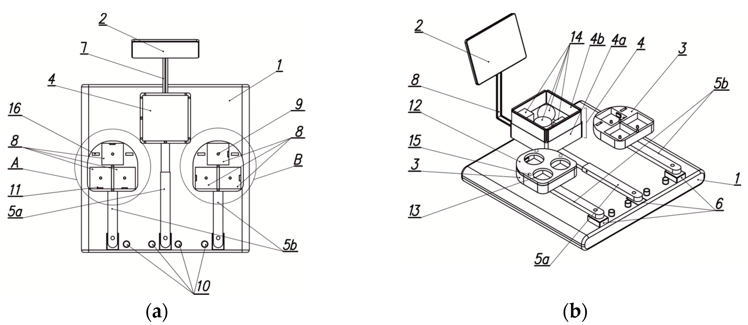
Figure 2.
Characteristic Stages of the Device Design Process.
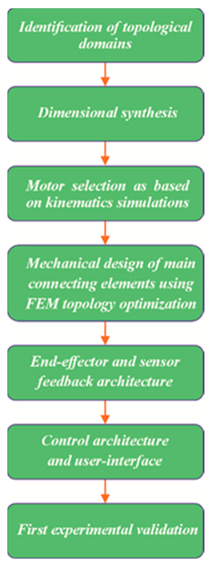
Figure 3.
Identification of the hand access area: (a) Basic area (b) Model of the hand manipulation area for individuals with disabilities.
Figure 3.
Identification of the hand access area: (a) Basic area (b) Model of the hand manipulation area for individuals with disabilities.
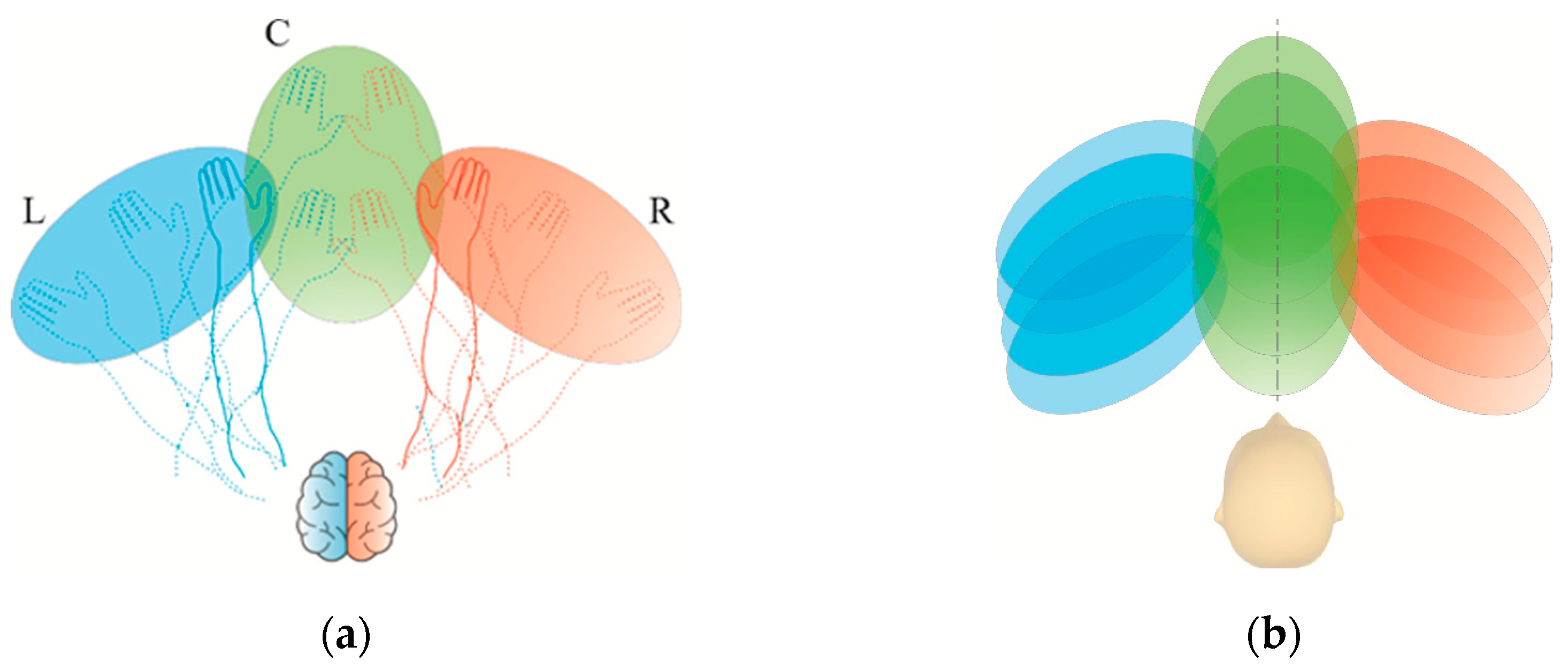
Figure 4.
Successive phases of the anatomical system from an open to a clenched hand (a)–(d).
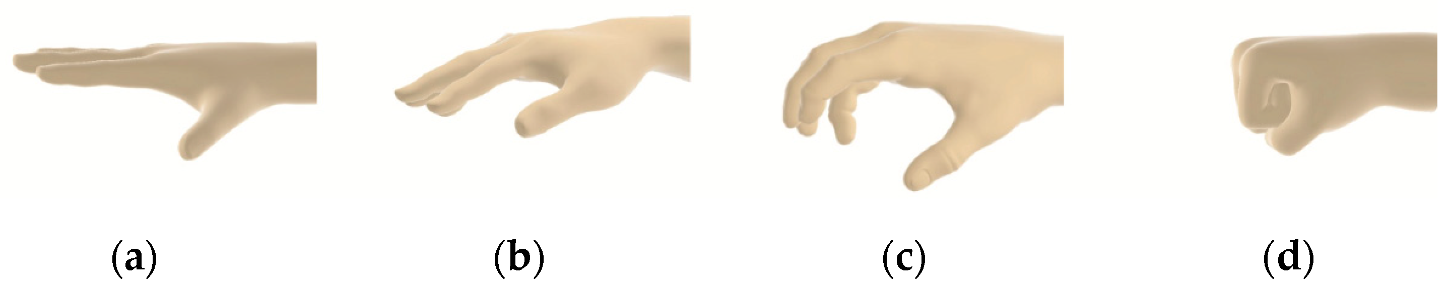
Figure 5.
Hand rehabilitation device: (a) Isometric view of the model, (b) Top view, left storage unit with one of the overlays.
Figure 5.
Hand rehabilitation device: (a) Isometric view of the model, (b) Top view, left storage unit with one of the overlays.
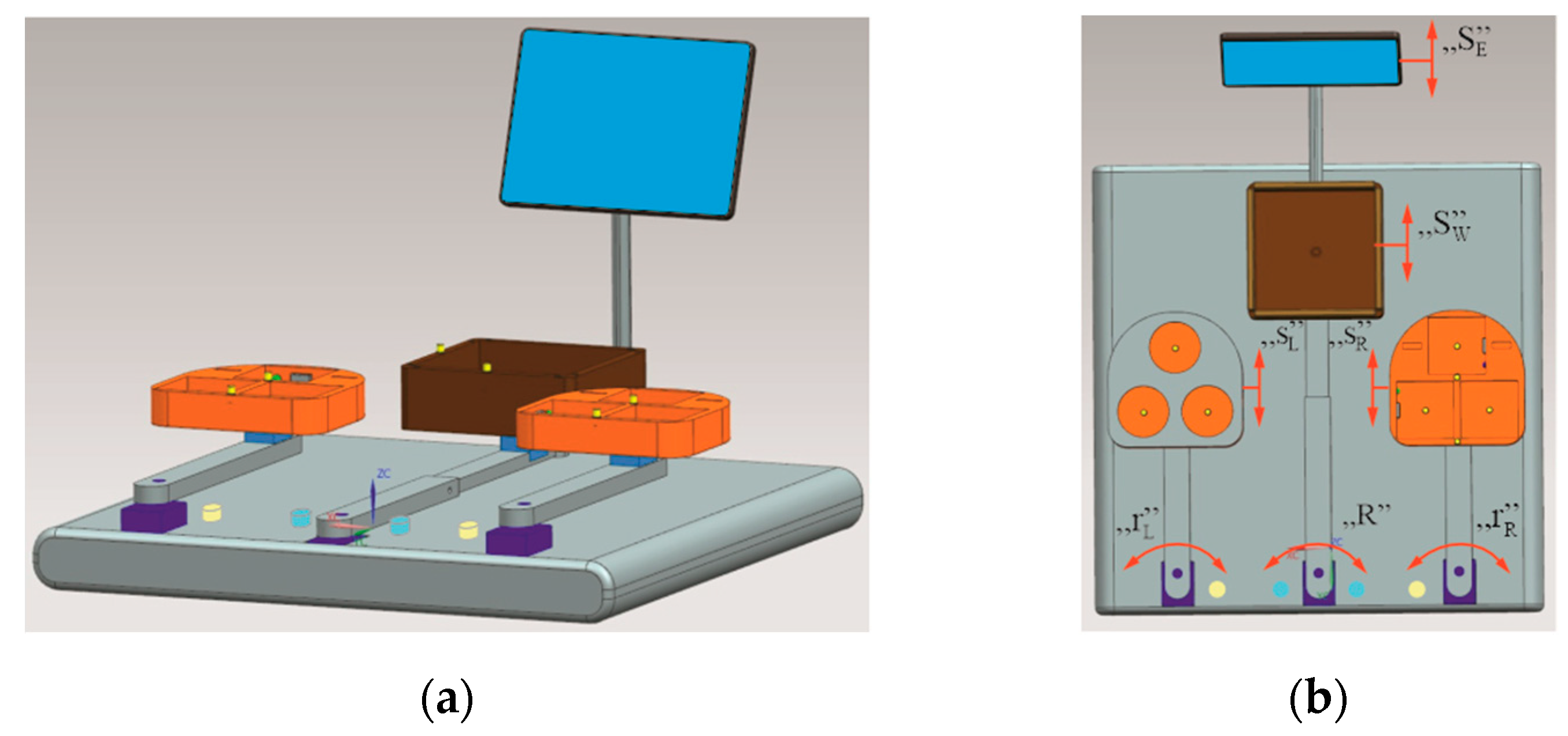
Figure 6.
Geometric variations of spherical objects (a) and physical object models (b).
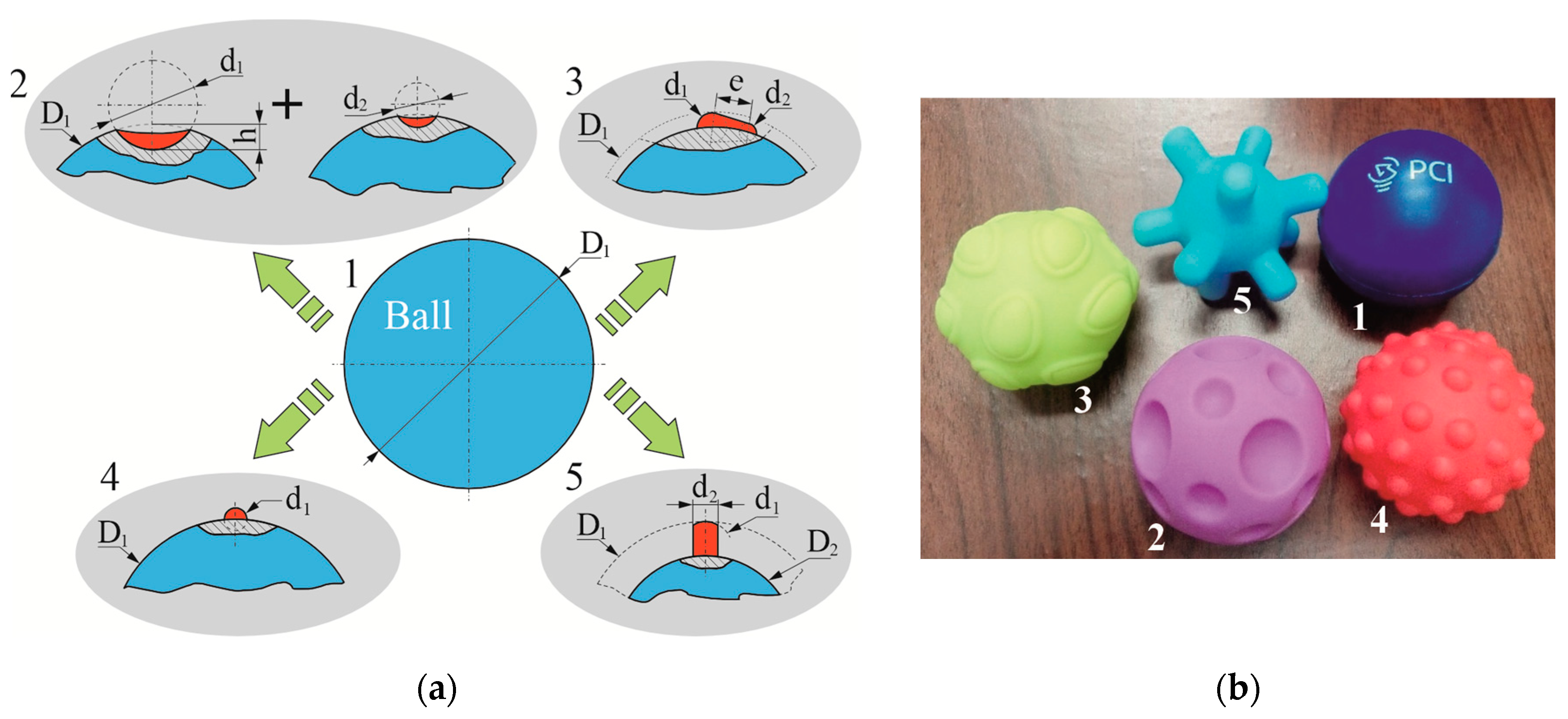
Figure 7.
Geometric variations of cubic objects (a) and physical object models (b).
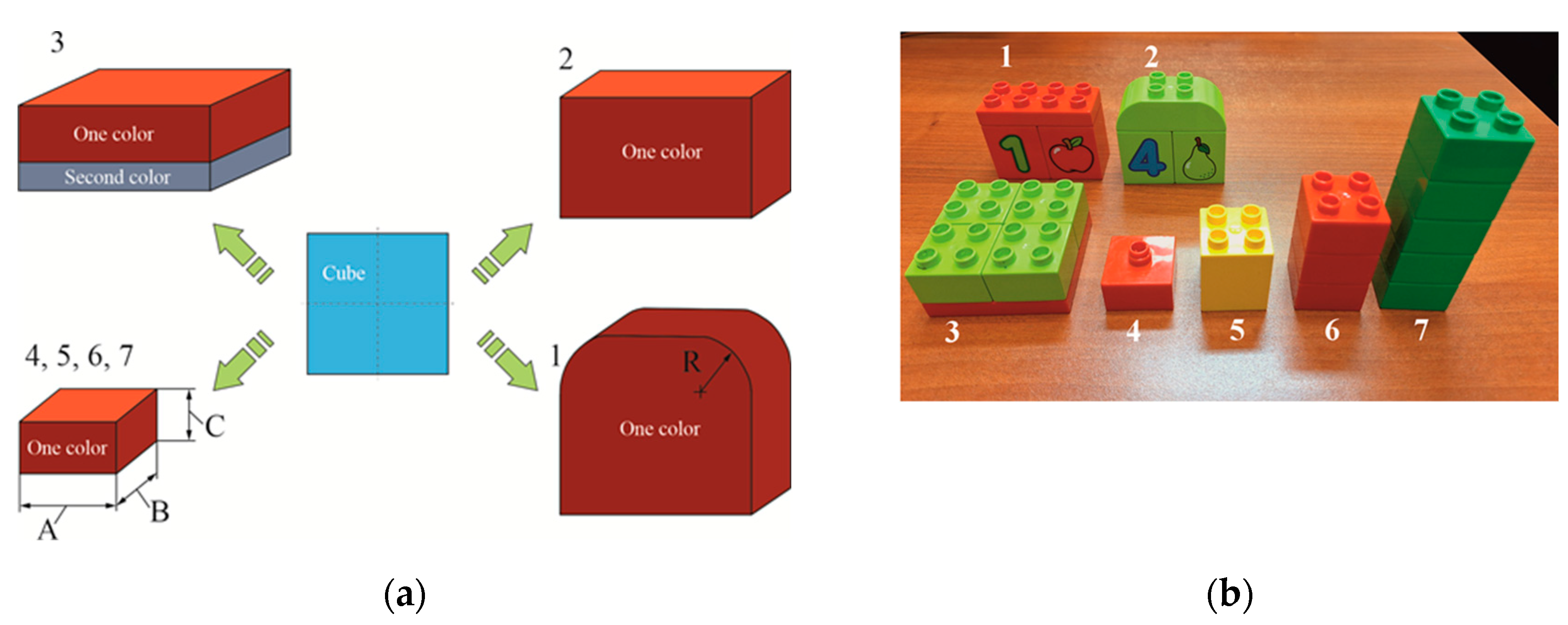
Figure 8.
Sample overlays for the mechatronic rehabilitation device.
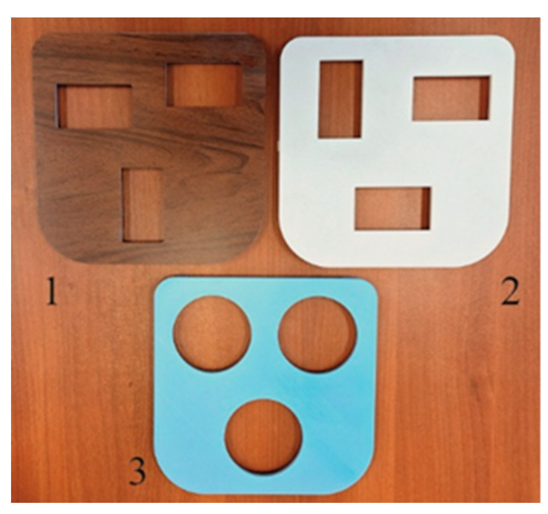
Figure 9.
Main components of the device control system: (a) microcomputer with enclosure, (b) 10.1" colour touchscreen, (c) sensor and its electronic system for object colour identification, (d) servo drive controller.
Figure 9.
Main components of the device control system: (a) microcomputer with enclosure, (b) 10.1" colour touchscreen, (c) sensor and its electronic system for object colour identification, (d) servo drive controller.
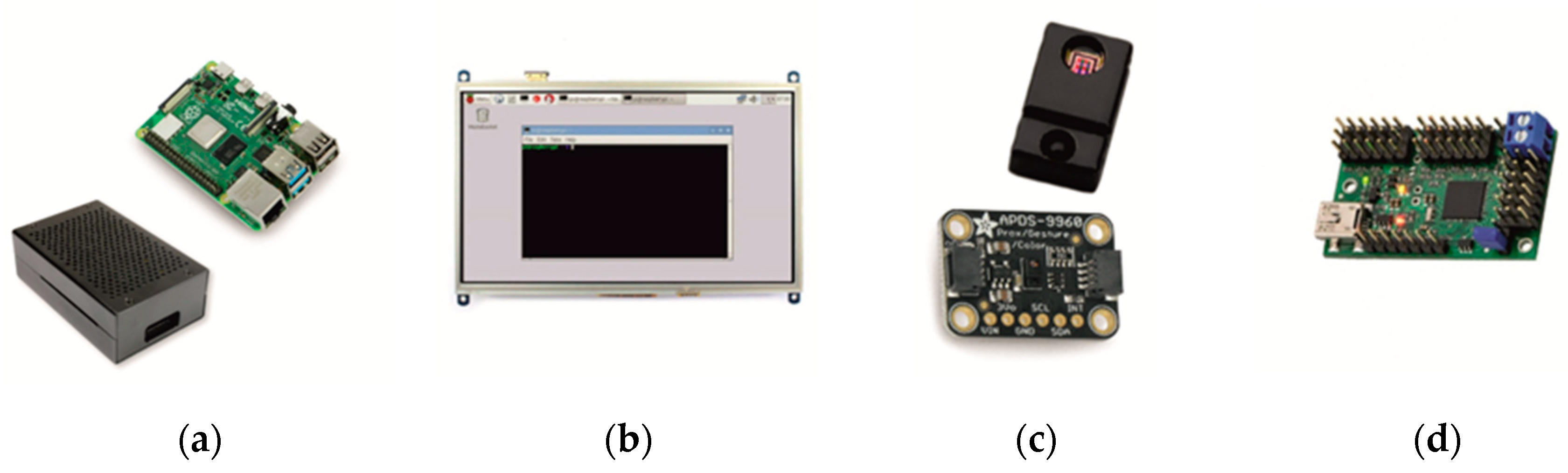
Figure 10.
LED system and object identification sensors within the storage unit: (a) schematic diagram, (b) preliminary arrangement of storage unit components and sensors (1-sensor, 2-LED).
Figure 10.
LED system and object identification sensors within the storage unit: (a) schematic diagram, (b) preliminary arrangement of storage unit components and sensors (1-sensor, 2-LED).
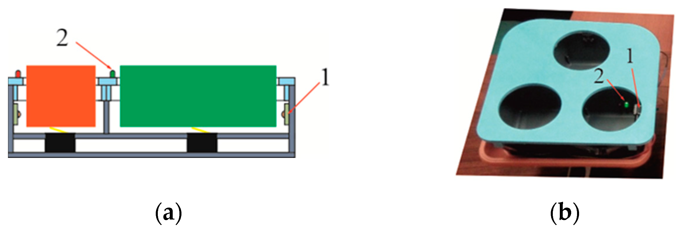
Figure 11.
Dialogue window of the servo controller programming application.
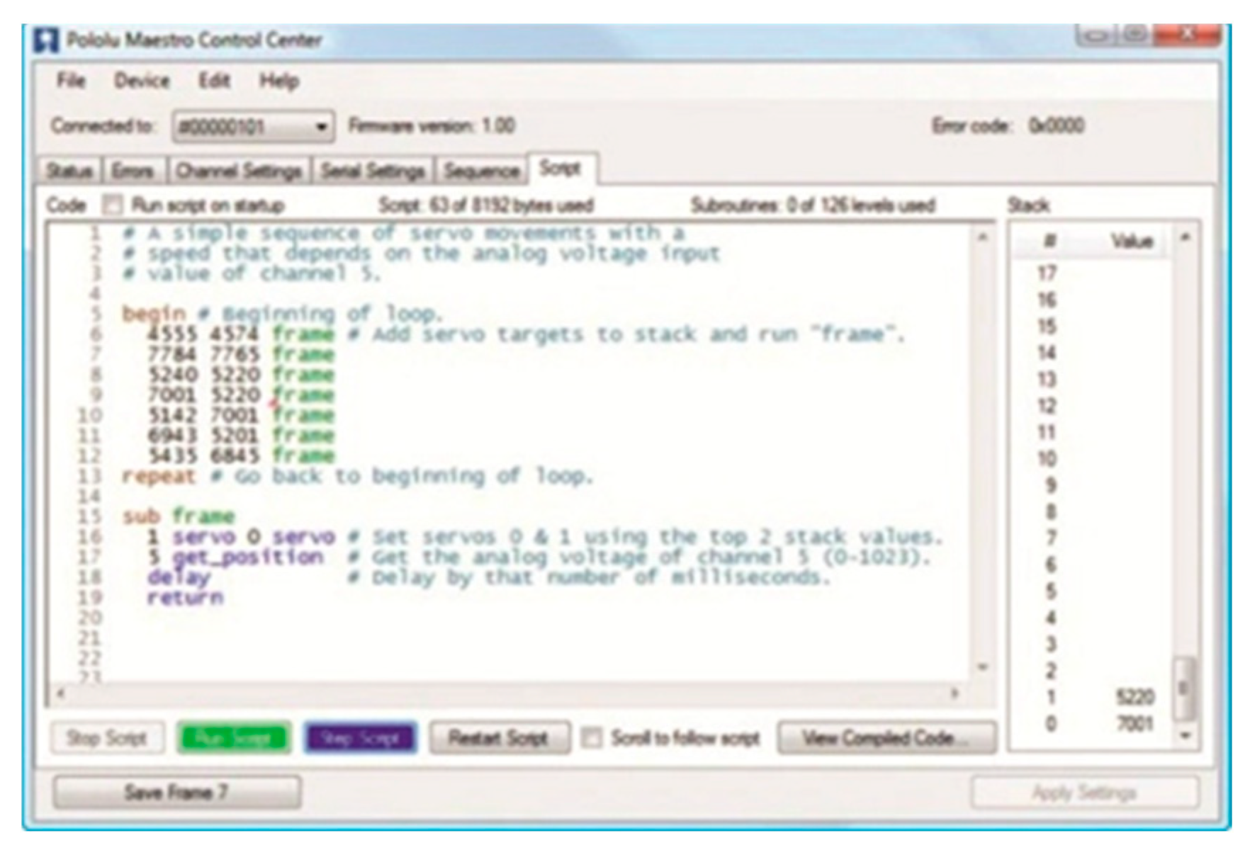
Figure 12.
Software and hardware testing environment.
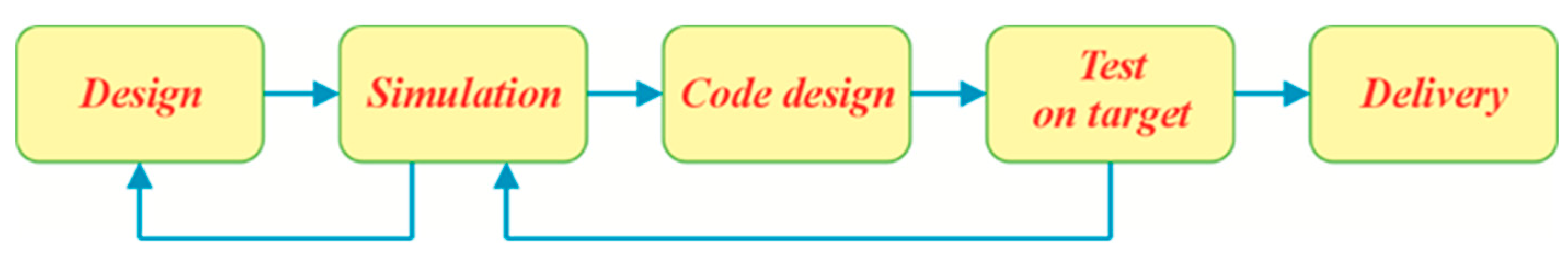
Figure 13.
Calibration system of the upper limb rehabilitation device.
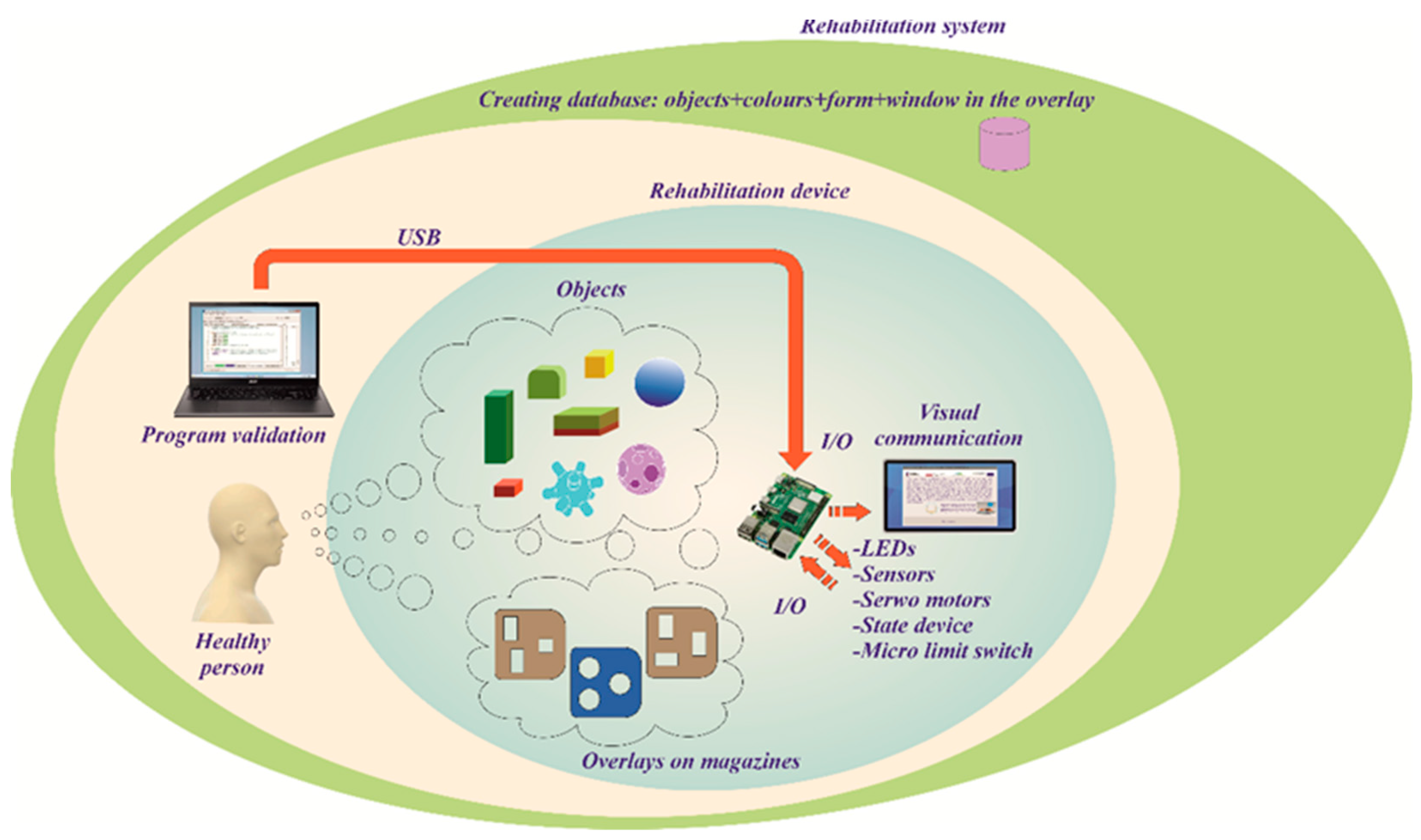
Figure 14.
Graphical interface of the upper limb rehabilitation device, windows: (a) start screen, (b) information panel of the programme.
Figure 14.
Graphical interface of the upper limb rehabilitation device, windows: (a) start screen, (b) information panel of the programme.
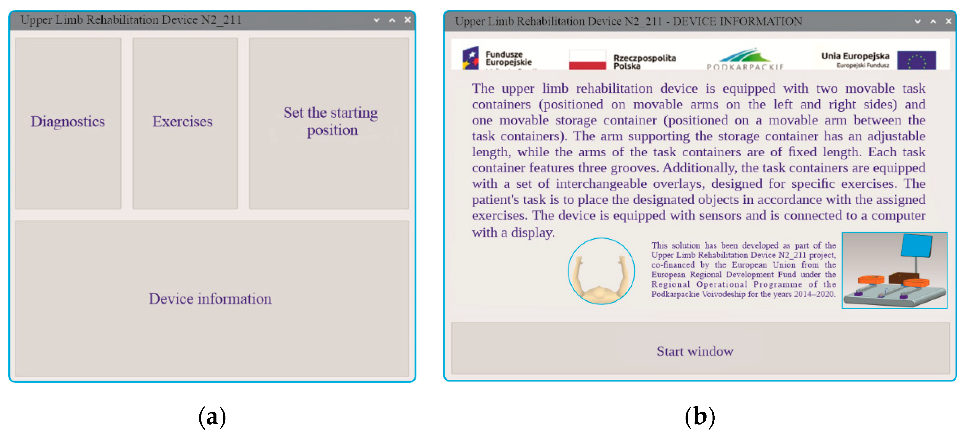
Figure 15.
Graphical interface of the upper limb rehabilitation device, windows: (a) diagnostics in three rounds, (b) sample report generated during the diagnostics process.
Figure 15.
Graphical interface of the upper limb rehabilitation device, windows: (a) diagnostics in three rounds, (b) sample report generated during the diagnostics process.
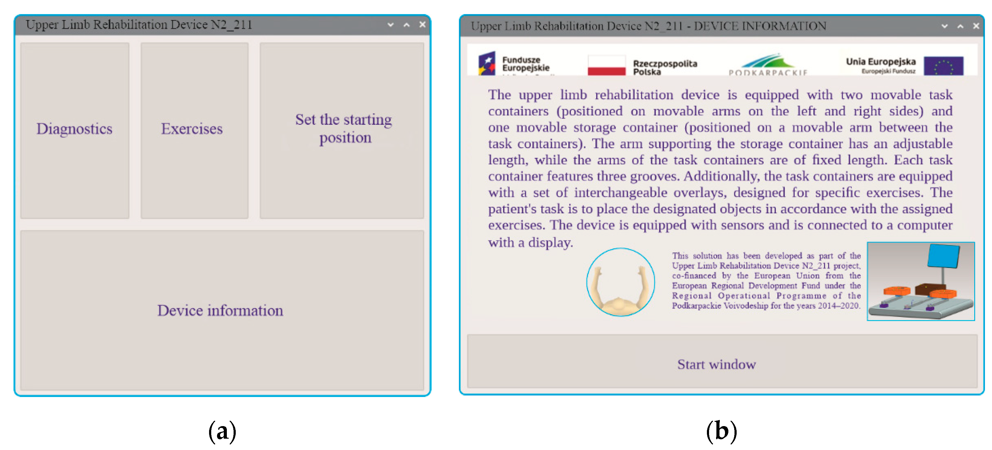
Figure 16.
Graphical user interface of the upper limb rehabilitation device. Window: exercise difficulty selection.
Figure 16.
Graphical user interface of the upper limb rehabilitation device. Window: exercise difficulty selection.
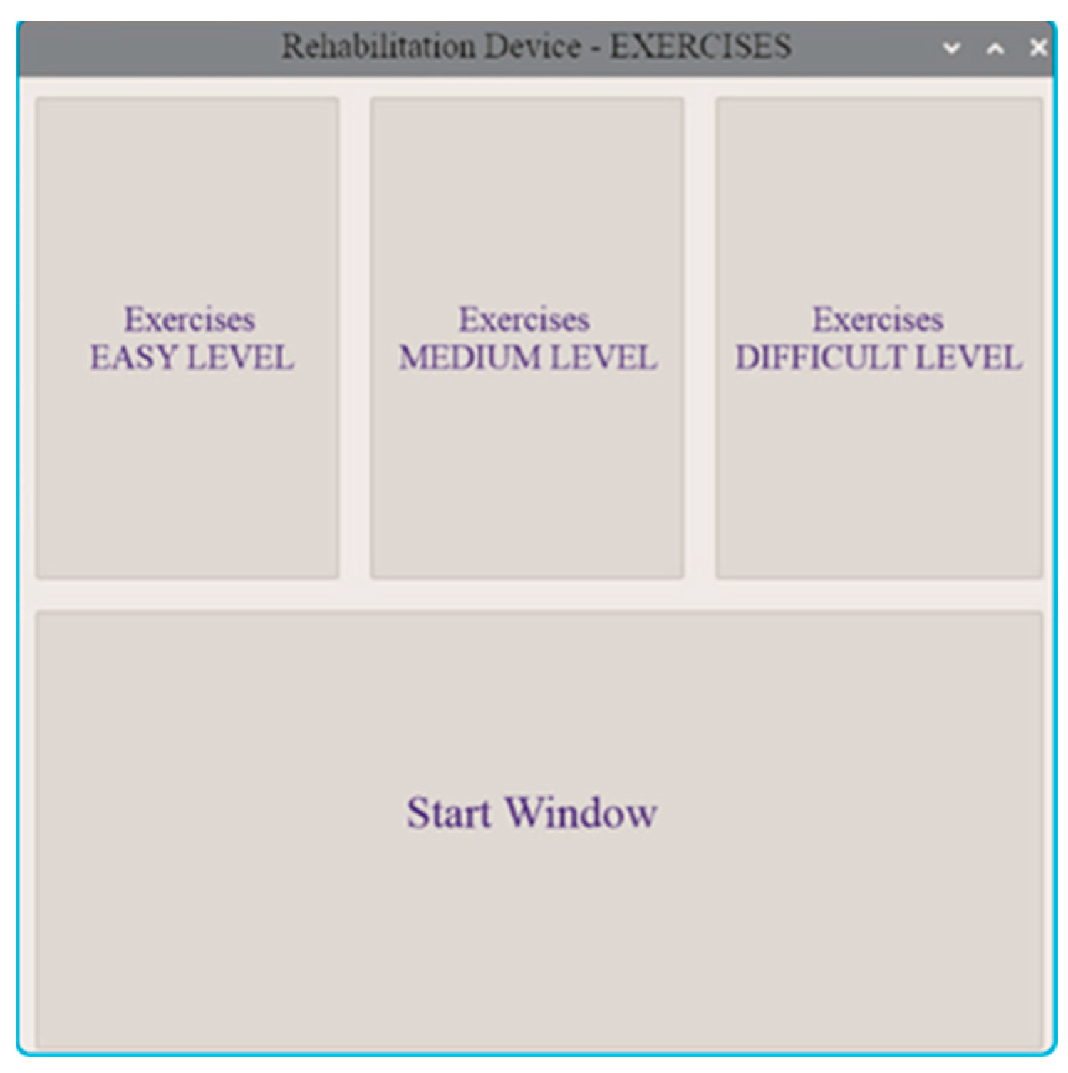
Figure 17.
Graphical user interface of the upper limb rehabilitation device. Windows: (a) exercise selection at the easy level, (b) report of a completed easy-level exercise.
Figure 17.
Graphical user interface of the upper limb rehabilitation device. Windows: (a) exercise selection at the easy level, (b) report of a completed easy-level exercise.
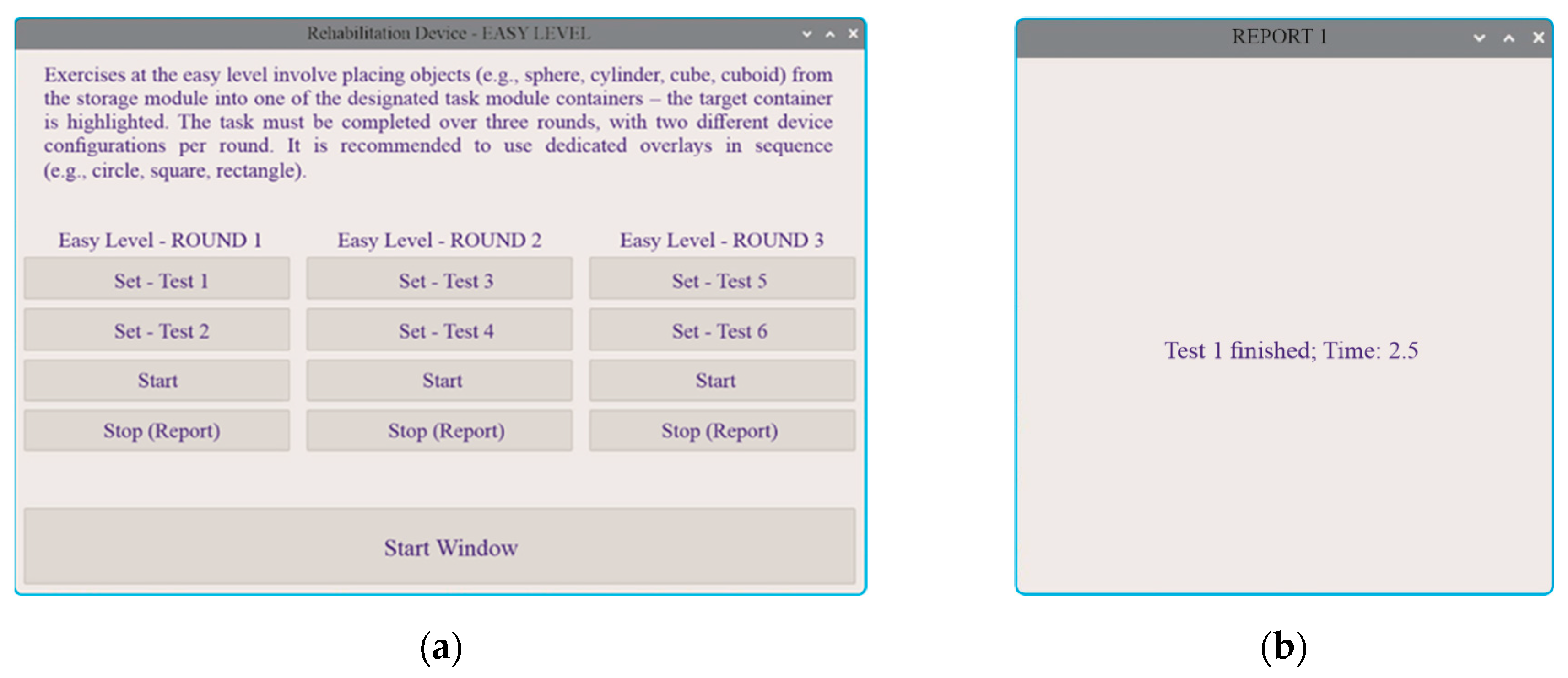
Figure 18.
Graphical user interface of the upper limb rehabilitation device. Windows: (a) exercise selection at the medium level, (b) report of a completed medium-level exercise.
Figure 18.
Graphical user interface of the upper limb rehabilitation device. Windows: (a) exercise selection at the medium level, (b) report of a completed medium-level exercise.
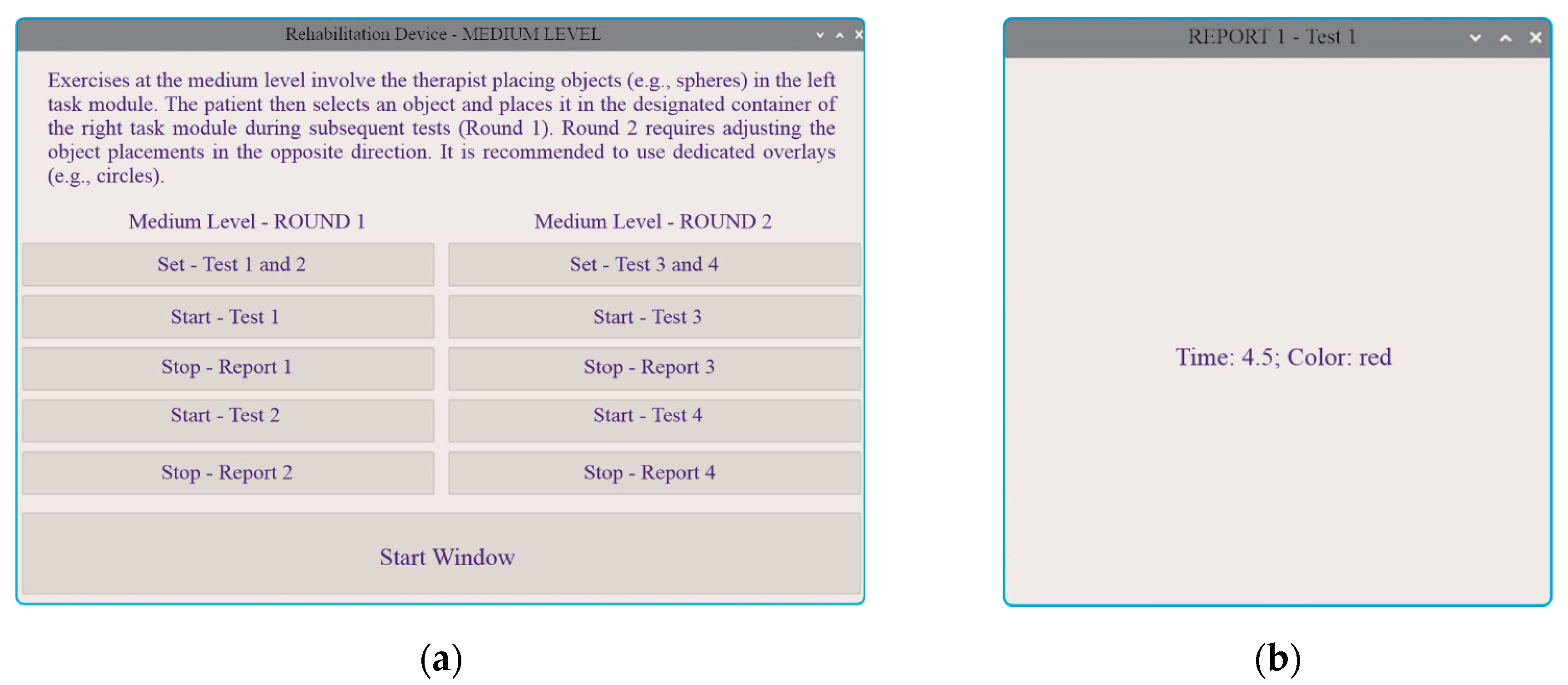
Figure 19.
Graphical user interface of the upper limb rehabilitation device. Windows: (a) exercise selection at the hard level, (b) report of a completed hard-level exercise.
Figure 19.
Graphical user interface of the upper limb rehabilitation device. Windows: (a) exercise selection at the hard level, (b) report of a completed hard-level exercise.
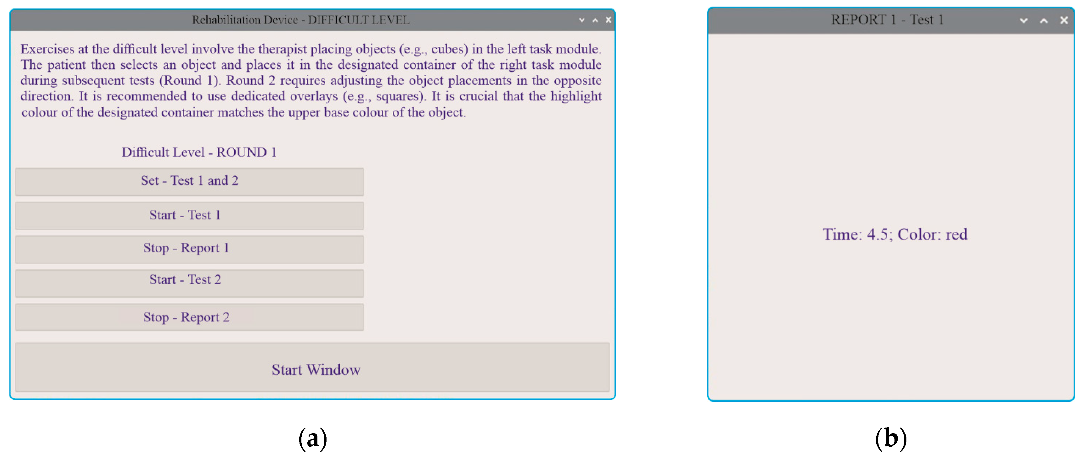
Figure 20.
Results from the diagnostics module – Round 1 (storage module and both task modules aligned straight at a 0-degree angle).
Figure 20.
Results from the diagnostics module – Round 1 (storage module and both task modules aligned straight at a 0-degree angle).
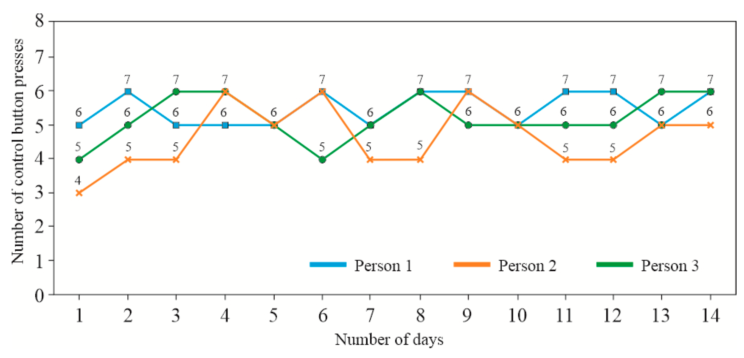
Figure 21.
Results from the diagnostics module – Round 2 (storage module aligned straight at a 0-degree angle, while the two task modules are tilted outward at a 30-degree angle).
Figure 21.
Results from the diagnostics module – Round 2 (storage module aligned straight at a 0-degree angle, while the two task modules are tilted outward at a 30-degree angle).
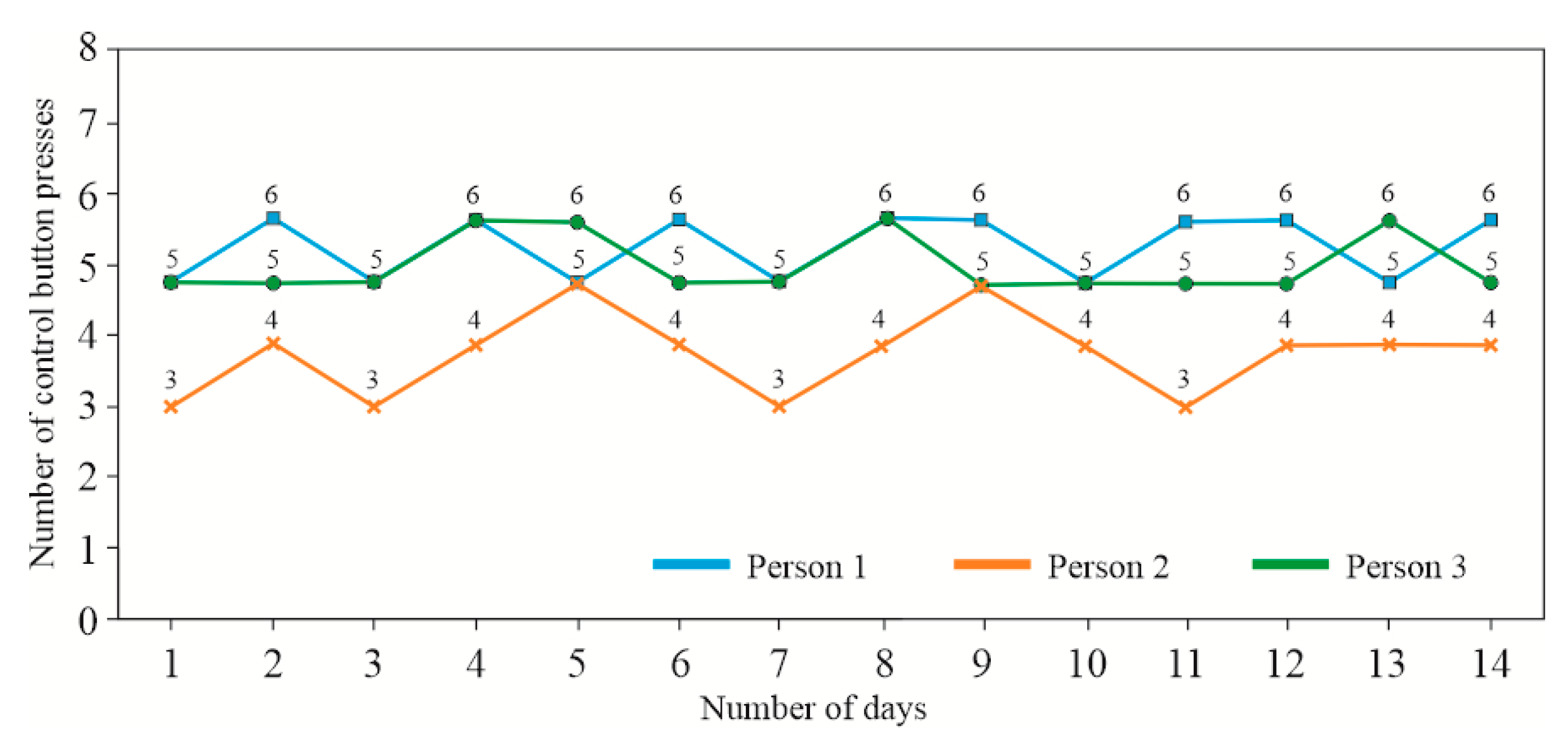
Figure 22.
Results from the diagnostics module – Round 3 (storage module aligned straight at a 0-degree angle, while the two task modules are tilted outward at a 60-degree angle).
Figure 22.
Results from the diagnostics module – Round 3 (storage module aligned straight at a 0-degree angle, while the two task modules are tilted outward at a 60-degree angle).
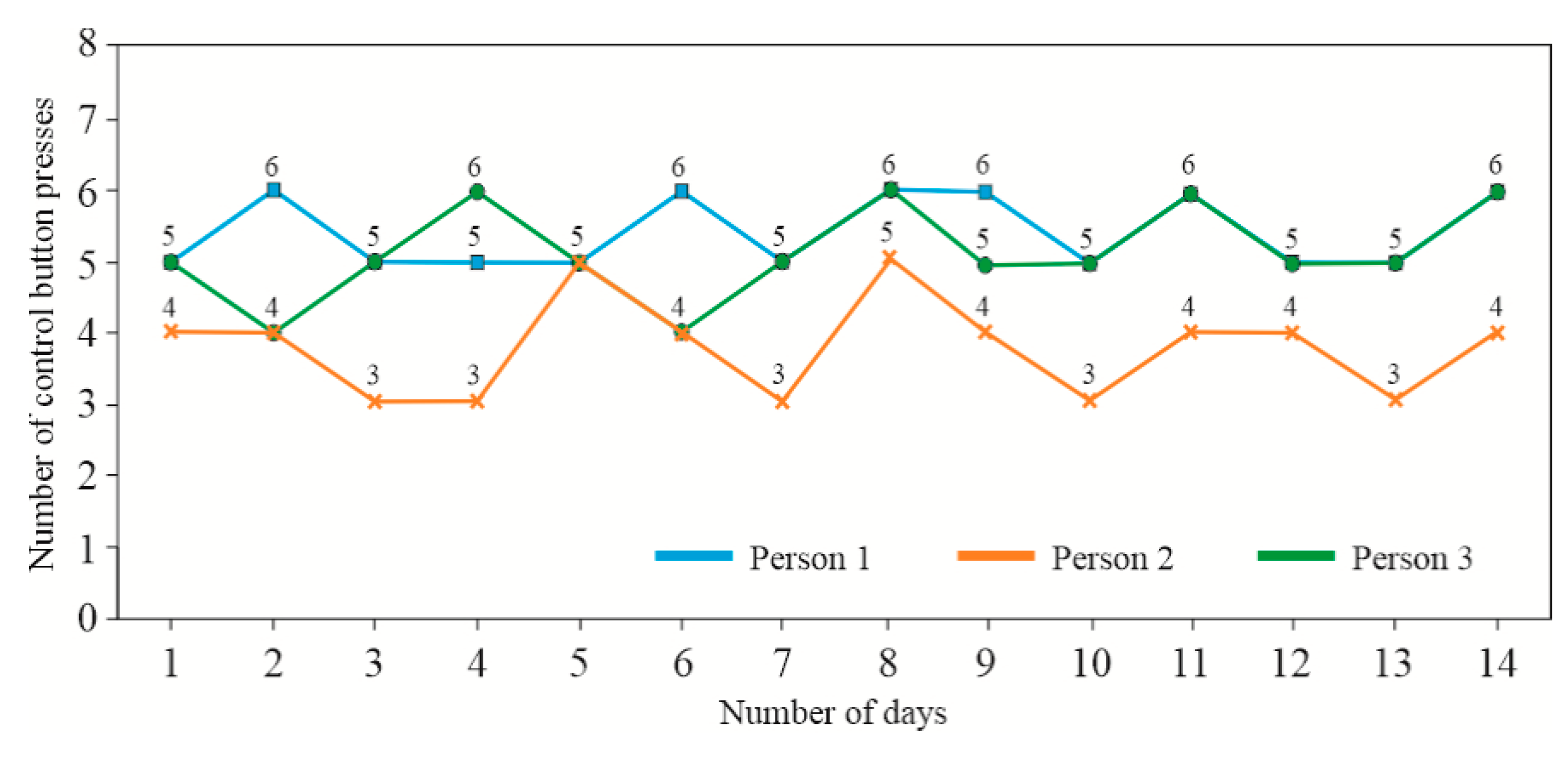
Figure 23.
Results from the easy-level exercise module round – 2.
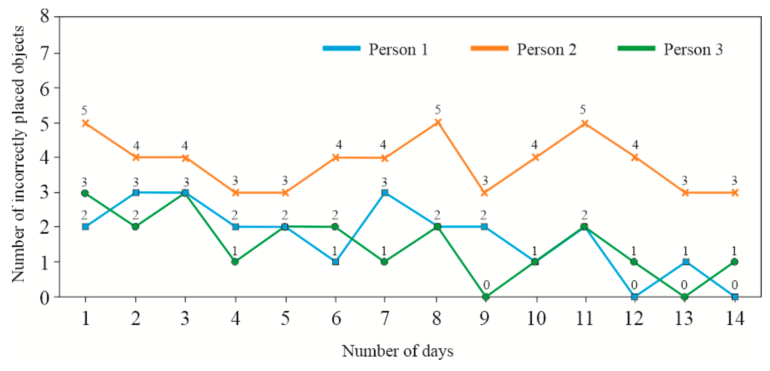
Figure 24.
Results from the difficult-level exercise module obtained by Participant No. 1.
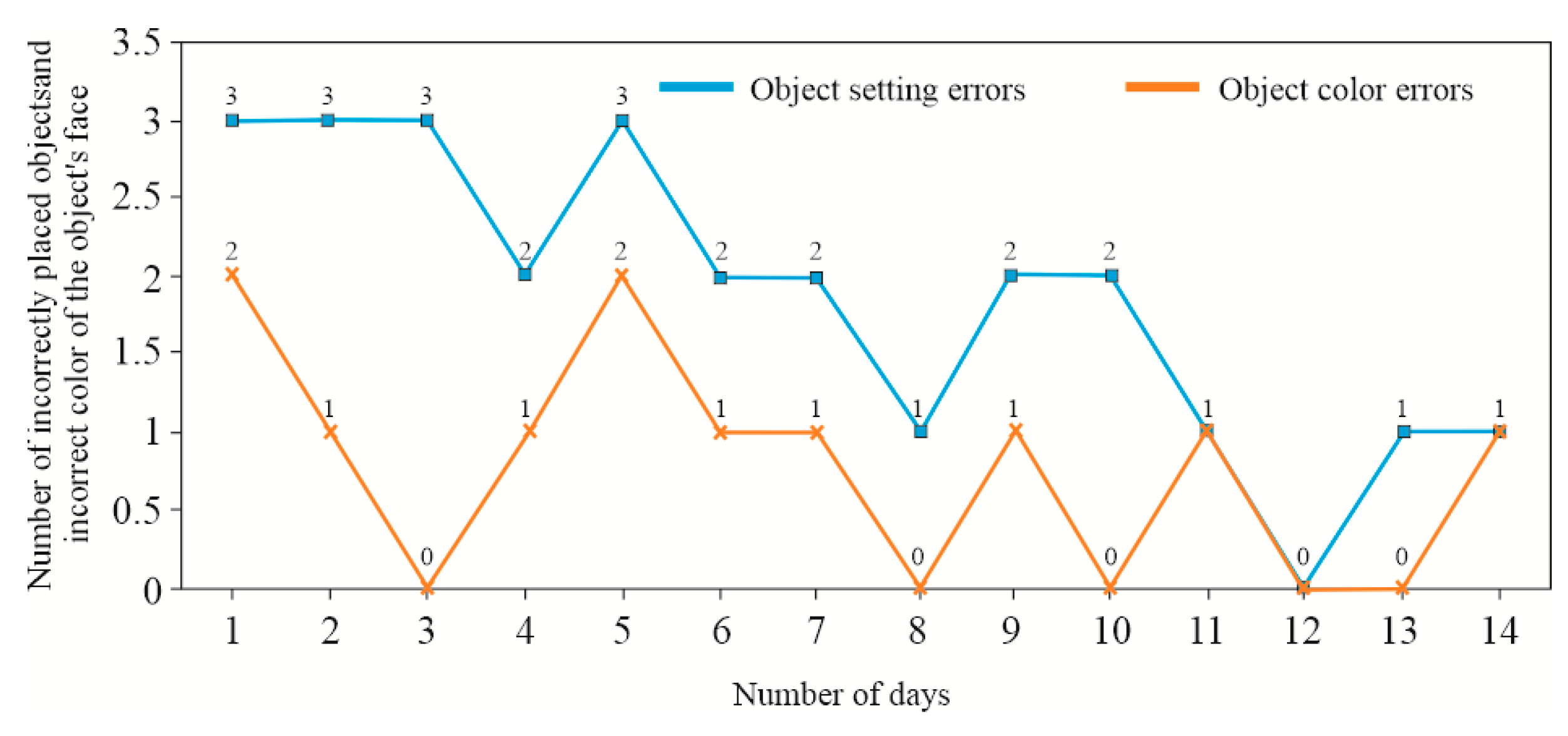
Figure 25.
Results from the difficult-level exercise module obtained by Participant No. 2.
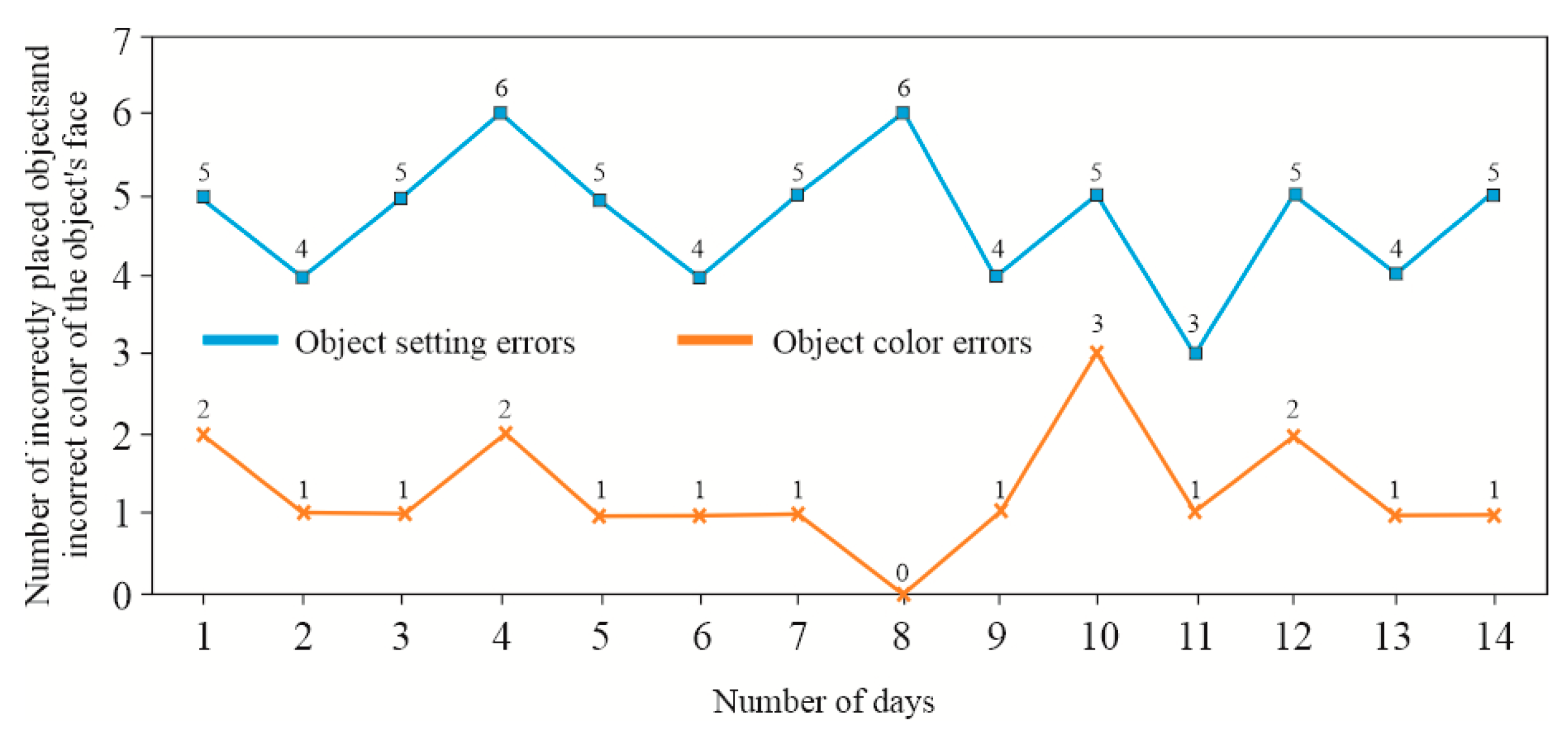
Figure 26.
Results from the difficult-level exercise module obtained by Participant No. 3.
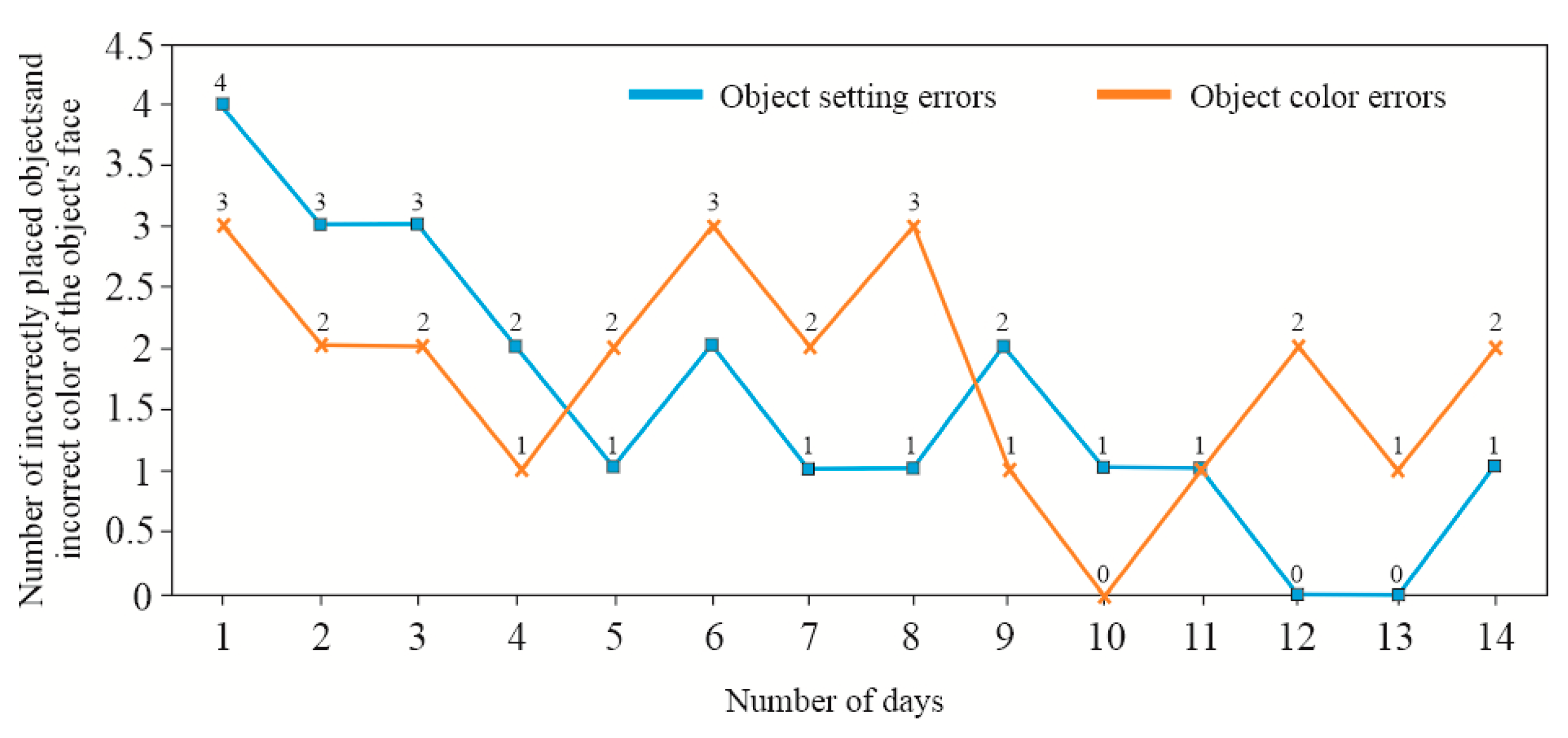

Table 1.
Geometry of spherical models used for calibration and initial testing.
| Dimensions, [mm] | Object number | ||||
|---|---|---|---|---|---|
| 1 | 2 | 3 | 4 | 5 | |
| D1 | 62 | 70 | 62 | 64 | 72 |
| D2 | - | - | - | - | 40 |
| d1 | - | 58 | 15 | 8 | 16 |
| d2 | - | 29 | 8 | - | 12 |
| h | - | 0.05×d1,2 | - | - | - |
| e | - | - | 9 | - | - |
|
Number of indentations/bulges |
0 | 9; 12 | 14 | 65 | 10 |
Table 2.
Geometry of cubes used for calibration and initial testing.
| Dimensions, [mm] | Object number | ||||||
|---|---|---|---|---|---|---|---|
| 1 | 2 | 3 | 4 | 5 | 6 | 7 | |
| A | 64 | 62 | 64 | 32 | 32 | 32 | 32 |
| B | 32 | 32 | 64 | 32 | 32 | 32 | 32 |
| C | 54 | 64 | 34 | 19 | 43 | 62 | 100 |
| R | - | 19 | - | - | - | - | - |
Disclaimer/Publisher’s Note: The statements, opinions and data contained in all publications are solely those of the individual author(s) and contributor(s) and not of MDPI and/or the editor(s). MDPI and/or the editor(s) disclaim responsibility for any injury to people or property resulting from any ideas, methods, instructions or products referred to in the content. |
© 2025 by the authors. Licensee MDPI, Basel, Switzerland. This article is an open access article distributed under the terms and conditions of the Creative Commons Attribution (CC BY) license (http://creativecommons.org/licenses/by/4.0/).
Copyright: This open access article is published under a Creative Commons CC BY 4.0 license, which permit the free download, distribution, and reuse, provided that the author and preprint are cited in any reuse.


