
Submitted:
12 March 2025
Posted:
13 March 2025
You are already at the latest version
Abstract
The principles of the friction welding (FW) process of the two different non-ferrous metals, aluminum and copper, are presented in this paper. Considering that the bimetallic Al-Cu joints find applications in electrical engineering, as well as in other industrial fields, the basic characteristics and compatibility of these metals are discussed, along with the influence of various parameters on the properties of their friction welded joint. The experimental study involved determining and analyzing the effects of process parameters on the occurrence, shape, and level of plastic deformation resulting from changes in the physical model during the rotational friction welding process (RFW). The specificity of the joining process is in the occurrence of various phenomena in the weld zone, which are significantly affecting the physical, structural, and mechanical properties of the base materials, thus influencing the joint quality. The friction welding process itself is complex, and the task is further complicated by the use of different base materials.
Keywords:
friction welding
; aluminum
; copper
; friction time
; friction pressure
1. Introduction
Welding of copper and aluminum using the conventional welding techniques is highly challenging due to the high thermal diffusivity of these metals. The friction welding is often used as a solid-state welding technique to overcome this challenge. During the friction welding, metals do not transform into the liquid phase; instead, they reach a visco-thermoplastic state in which, under pressure, the permanent plastic deformation occurs, enabling the formation of a bond, [1]. The most important advantage of friction welding is the fact that it achieves a perfect weld, that is to say an integral weld (weld the surface and not the circumference) because the parts are forged/welded into one set. Friction welding is carried out sustainably. The great advantage of this welding technique lies in the fact that some combinations of materials are easily welded, while they cannot be welded by the traditional welding techniques [2]. The rotational friction welding (RFW) of various metals and corresponding analyses are given in [3,4,5,6,7]. The friction welding stands as a suitable welding method widely applied for joining Al and Cu in the electrical industry, thermo-technology, and various other applications across industrial practices [8,9] including application in nuclear industry [10]. In addition to rotary friction welding (applied in this study for joining cylindrical elements), the development of advanced welding technologies and the focus of contemporary research also encompasses processes such as Friction Stir Welding (FSW) or Friction Stir Spot Welding (FSSW) welding (for joining plate or sheet metal components) [11,12,13].
The friction welding of aluminum and copper ensures a high-quality joint. The welding process is brief and cost-effective, as it requires no additional materials, gases, or chemicals, unlike in other welding methods. Additionally, no extra energy is needed, and the minimum sample preparation before the welding is sufficient, as the process itself extrudes any residual oxides, oils, or other contaminants, ensuring that only the clean metals are in contact [8]. In addition, the friction welding process is environmentally friendly. Detailed microstructural research results on Al-Cu welded joints are presented in some previous research [14,15,16,17].
Researchers in this field, during the parametric optimization of the friction welding process, consider the friction time as the most influential factor, followed by friction pressure and compression, and rotational speed [7,18,19,20]. It has also been determined that these parameters directly impact the level of plastic deformation, mechanical characteristics of the welded joint and microstructural changes, [21,22,23]. For instance, it was found that the friction time and friction pressure influence the tensile strength of the joint [5].
The friction welding process of copper and aluminum parts was, in this research, studied experimentally and by simulation. The experimental section of this study involved welding of samples usually used in the electrical industry, followed by preparing the samples for further examination of mechanical and microstructural characteristics. The influence of friction time on the shape and size of the obtained plastic deformation in these joints was analyzed, and the hardness values were measured in the joining zone.
2. Literature Review
Since some of the common features of different groups of references used in this research are briefly explained in the introductory section, this literature review is focused only on some of the most important of them, characteristic for those groups.
Jin et al. 2023 [3] were studying the heat-pattern (HP) induced non-uniform radial microstructure and properties of the rotary friction welded Ti-6Al-4 V joint. They distinguished the two types of HP, the “glass-like” HP and the “scissor-like” HP. The former one results at low rotational speeds (500 to 1200 rpm), when the joint squeezes the interfacial plasticized metal towards and accumulated at periphery, and the axial tensile stress is not sufficient to flip the metal into the extruded flash. The latter HP is formed, at higher rotational speeds (1500 to 1800 rpm), when the plasticized metal would flow to and would be extruded at the periphery. The non-uniform radial microstructures cause the non-uniform radial properties.
Kimura et al. 2024 [5] have analyzed fracture of the friction welded joint between pure nickel and aluminum with post-weld heat treatment (PWHT). The joint fracture temperature increased with increasing width of the intermetallic compounds (IMC) interlayer in the axial direction of the joint. The fracture of the joint occurred at the interface between NiAl layer and Al base metal, due to PWHT induced decrease of the interface bonding strength. However, the joint fracture temperature drastically increased up to about 800 K when the width of the IMC interlayer exceeded 50 mm.
Liang et al. 2015 [6] studied the dissimilar friction welding of Al and Mg bars and evaluated the interfacial microstructure characteristics of the Al-Mg alloy using optical and scanning electron microscopy, and the X-ray diffraction. Experimental results showed that intermetallic compounds (IMCs), were generated in the interfaces of the Al and Mg alloys, with the thickness of IMCs decreasing with the friction and forge pressure increase. Heavy thickness of IMCs layers seriously deteriorated the mechanical properties of the joints, with hardness at the interfaces being higher than that of the base material due to the IMCs’ presence.
Shubhavardhan et al. 2012 [7] considered development of the solid-state joints of dissimilar materials, AA6082 aluminum alloy and AISI 304 stainless steel, formed by the continuous drive friction welding process (CDFW). With increasing the friction pressure and friction time, the joint strength increased, and then decreased after reaching the maximum. The presence of contaminants at the interface of the metals reduced the joint quality. The surface finish operations did not affect the welding properties significantly. Hardness of both materials in the vicinity of the weld interface was higher than those of the base metals.
Gavalec et al. 2023 [9] experimentally studied the effect of the contact surfaces geometry on the quality and mechanical properties of a rotary friction weld (RFW) of the titanium alloy Ti6Al4V, testing three types of geometry: flat on flat, flat on 37.5° and flat on 45°. Results have shown that the best was the flat geometry, since it resulted in the least saturation with interstitial elements from the atmosphere, while the other two geometries were found as not suitable for the RFW of the titanium alloy Ti6Al4V. Fracture in the RFW zone was brittle, while the pure ductile fracture occurred in the heat affected zone (HAZ).
Dellepiane et al. 2025 [10] have presented the design process and functionality of a laboratory-scale friction welding setup, which was designed to use the load cell, what enabled monitoring of the welding parameters. A change in the hardness along the weld interface was recorded, as well as changes in the microstructure of the Ca104 alloy, what was ascribed to the grains experiencing the dynamic recrystallisation during the welding. The flexural strength of the welded joints was higher than that of the base material.
Singh et al. 2012 [11] have analyzed the influence of axial force on the mechanical and metallurgical properties of FSW joints of Al alloy AA6082-T65. The axial force was varied within range 3 to 8 kN on the surface of the base material. No macro structure defects were observed for the force values between 4 to 7 kN; the maximum weld tensile strength (266 MPa) was obtained for the axial force of 6 kN, which was 85 % of the base metal value.
Veljic et al. 2024 [12] studied the FSW of plates made of the high strength Al alloy 2024-T3 of 3 mm thickness, specifically the tool plunge stage, which precedes the formation of the T-joint. Authors pointed that an increase of the tool rotation speed increases the temperature in the welding zone, creating conditions for eliminating the joining line, while the same effect was exhibited by an increase of the tool pin length.
Zhu et al. 2022 [13] investigated the continuous drive friction welding of 6061-T6 Al and copper, and concluded that with an increase in rotation speed, the width of the welded zone gradually increases, with the generation of higher temperatures. The microhardness on the bonding surface was significantly greater than those of the base materials due to the presence of IMCs, while the softening zone was formed on both sides of the bonding surface, becoming more significant with an increase in the rotation speed.
Bauri et al. 2024 [15] explored the effects of various pre-weld and post-weld heat treatments (PWHTs) on the microstructural and mechanical properties of the rotary friction welded (RFW) joints of the two dissimilar aluminum alloys, AA7075 and AA2024. The joints exhibited increased flash formation on the AA7075 side due to its lower melting point. All welds failed in the heat affected zone (HAZ) of the AA2024 alloy side, due to the development of coarse grains, pointing that this area was the weakest link in the joint.
Wei et al. 2015 [16] have analyzed the joints between Al and Cu bars obtained by continuous drive friction welding (CDFW). The interface layers’ temperatures were within range of 648 to 723 K, at different welding parameters. The interdiffusion between Al and Cu atoms was extraordinarily rapid, as the interdiffusion coefficients reach 7.8 × 10⁻¹² m2/s.
Milasinovic et al. 2024 [17] aimed to enhance the efficiency and efficacy of the Al/Cu friction joint production process, by obtaining sound joints within a very short welding time. Authors investigated the accuracy and the quality of the continuous drive friction welding (CDFW) process, and the optimum combination of its parameters. The thermal imaging showed the actual total welding time was 15% longer than the nominal value. The Al/Cu joints produced at welding pressures below 88.9 MPa often displayed the presence of non-joined micro-regions at the Al/Cu interface. At the friction pressure set at 66.7 MPa, an increase in the forging pressure to 222.2 MPa eliminated the presence of non-joined micro-regions.
Tashkandi and Mohamed 2020 [18] have investigated the effect of friction time on the mechanical properties of AA6061 joints made by the CDFW. They found that AA6061 does not require a forging stage and the solid joints did not fracture within the welding zones. The thermal profiles of the welding times indicated that the peak temperature is reached within 3 to 4s of the welding process regardless of the duration of the welding procedure. Any further increase of the friction time does not increase the temperature beyond the peak one, but helps annealing the material.
Mahajan et al. 2023 [19] investigated the changes in the microstructural and mechanical properties of various pre- and post-weld heat treatments (PWHTs) on rotary friction welded of AA7075 and AA5083 aluminum alloys. They focused on evolution of the weld’s macro and microstructures, and changes in hardness and tensile properties. Due to the continuous dynamic recrystallization, significant grain refinement was observed at the weld interface, in the dynamic recrystallized zone – DRZ, while in thermo-mechanically affected zone TMAZ, the region next to DRZ, the lower strain and high temperatures resulted in formation of deformed grains.
He et al. 2014 [20] have reviewed developments in the numerical analysis of friction stir welding processes, microstructures of friction stir welded joints and the properties of friction stir welded (FSW) structures. Authors discussed the main methods in numerical analysis of friction stir welding and illustrated with brief case studies, as well as certain important numerical modelling issues, such as materials flow modelling, meshing procedure and failure criteria.
In Gite et al. 2019 [21] the objective was to summarize the prominent research work in the field of friction welding, with emphasis on the methodology, workpiece materials, tool design and material, workpiece sizes, as well as the typical process parameters. Authors discussed the FSW principle and process parameters, like the tool geometry, tool rotational speed, tool traverse speed, joint design, as well as the welding parameters, with a short overview of numerical analysis of the FSW processes.
Sethi et al. 2021 [22] have presented a review on friction stir welding as a sustainable way of manufacturing. They analyzed publications on FSW of similar alloys (Al-Al), dissimilar alloys (Al-Mg), and effects of interlayer on similar alloys (Al/Cu/Al) and dissimilar alloys (Al/Zn/Mg). They also considered the effects of the process parameters on joining of materials by the FSW.
Cam et al. 2023 [23] have shown that the main difficulty in friction stir welding/friction stir spot welding (FSW/FSSW) of dissimilar Al-alloys is the lack of homogeneous mixing of materials due to the insufficient heat input, what leads to formation of inhomogeneous structure in the stir zone and low plasticity of the materials to be welded. For the successful FSW butt and lap joining of dissimilar Al-alloys one has to choose the optimum weld parameters, such as heat input, plate and tool positioning, and shoulder geometry, as well as the pin profile, while in the FSSW of these alloys, other parameters, such as tool plunge speed, tool plunge depth and dwell time are influential.
3. Experimental Procedure
3.1. Basic Properties of Aluminum and Copper
Aluminum is a silver-white metal categorized as a lightweight non-ferrous metal. The physical and mechanical characteristics of aluminum are unique and primarily depend on its purity. The melting temperature of aluminum is 660 °C. Aluminum is 3 times lighter than iron and 3.3 times lighter than copper. It exhibits very high corrosion resistance, it is non-magnetic, non-sparkling, it is not brittle at low temperatures and has good formability. Al is highly ductile; notably, 27 g of aluminum can be drawn to a length of 1000 m. This metal is an excellent electricity and heat conductor. Aluminum is not toxic.
Copper belongs to the group of heavy non-ferrous metals, characterized by a reddish color. Its mechanical properties largely depend on prior mechanical or thermal treatment. The melting temperature of copper is 1083 °C. Copper exhibits high plasticity; it is non-magnetic and resistant to corrosion. It is also an excellent electricity and heat conductor and it possesses antibacterial properties. The technical copper purity ranges from 99.0 to 99.7%, while the electrolytic-grade copper purity is between 99.9 and 99.99%.
The common characteristics of Al and Cu are corrosion resistance, high electrical and thermal conductivity, and good formability. Both metals have a face-centered cubic (FCC) crystal lattice structure. Aluminum possesses 60% of the electrical conductivity of copper. Therefore, an aluminum conductor of the same length as a copper conductor must have a cross-sectional area 1.6 times larger than that of copper to reach the same conductivity.
3.2. Compatibility of Aluminum and Copper
Copper and aluminum, due to their high electrical and thermal conductivity and corrosion resistance, have common applications in almost all the fields of modern technology, such as electrical conductors, elements of heating and cooling technology, architectural hardware, etc. Their common application often requires their joining, forming the bimetallic joints of certain structural elements. The joining of these two metals can be performed in two ways: with additional material (soft and hard soldering) and without additional material (friction welding, resistance welding, cold welding, ultrasonic welding, etc.).
In the electrical industry, a copper-aluminum terminal clamp, or a cable connector, is produced in certain cylindrical shapes. Examples are given in Figure 1, [24].
These connectors are used where an aluminum cable needs to be terminated with a copper busbar or copper contact. If cable lugs made solely of copper or solely of aluminum were used, there would be a galvanic effect due to the contact of different metals, or metals with a significant difference in electrode potential. The electrode potential of Al is - 1.662, and of Cu is + 0.337. Whenever the two different metals come into contact, the so-called galvanic effect occurs due to their different electrode potentials, resulting in corrosion on the surface of the metal of a lower electrode potential, and in this case, that is aluminum. This is the electrochemical corrosion of different metals. To avoid this phenomenon, bimetallic lugs (connectors) are manufactured using the friction welding. This ensures a technically sound and durable joint, fully suited for its intended purpose. Based on this, it can be said that aluminum and copper are compatible metals, considering certain properties and the quality of the obtained joint. However, the compatibility does not apply to every aspect of these metals’ properties. For example, Al and Cu have mutual affinity at temperatures above 120 °C, forming several different common phases in their joint. These intermetallic phases negatively impact the mechanical properties of the joint and thus its reliability. A significant advantage of the friction welding is that the process is relatively short, reducing the possibility of intermetallic phases formation.
3.3. The Mechanism of Al-Cu Joint Formation and Accompanying Formations During the Joining Process
Given the complexity of physical, mechanical, metallurgical, thermal, and chemical phenomena during the friction welding joining process of the two different metals, their joining mechanism is much more intricate than with homogeneous materials [9]. An alloy is formed between the surfaces of the two metals, and its properties can significantly influence the overall properties of the joint. The joining mechanism and the physical foundations of the joining process have been partially, but not fully explored. Therefore, there are still open questions that need to consider the influence of a series of relevant factors related to these processes and joining technology. In theory, there exist several hypotheses that define the joint formation process (diffusion, recrystallization, energy, dislocation, etc.), but none provides a complete solution, as the complexity of the answers is compounded by the fact that it involves welding of different metals.
The most acceptable theory is diffusion since the conditions for diffusion occur during the friction welding process, namely elevated temperatures and pressure.
The main characteristics of the joining mechanism in the friction welding process is that the metal contact surfaces need to approach to a distance of the order of the crystal lattice parameter. Since the real metal surfaces are not perfectly smooth, contact at the beginning of welding occurs only at the peaks of the surfaces’ irregularities, and an increase in the contact area is achieved by the plastic deformation of the coupled peaks. When the peaks are completely compressed, the contact surfaces distance approaches the order of the crystal lattice parameter, at which point the atoms of one metal enter the crystal lattice of the other metal, and vice versa. Since the radii of aluminum and copper atoms are of similar size (for Al it is 0.143 nm and for Cu it is 0.128 nm), bonds are formed allowing for the formation of substitutional mechanism common crystal lattices. The joining is based on formation of a metallic bond (solid solutions) between the base metals (aluminum and copper), all thanks to the diffusion phenomenon [1].
The interdiffusion between Al and Cu is accompanied by formation of an intermetallic layer. The width of the diffusion layer is related to the diffusion time, and the diffusion time is a function of the friction time. For example, with a friction time of 8 s, the width of the diffusion layer can be up to 10 μm [14]. This intermetallic formation contains saturated solid solutions Al (Cu) and Cu (Al), which form on both sides of the contact surfaces due to mutual diffusion. The level of released heat, or the achieved temperatures in the contact zone, depend on the friction time. The measured temperatures in that zone range from 350 °C to 500 °C [4]. Diffusion occurs relatively quickly due to elevated temperatures and pressure, as the diffusion coefficient between Al and Cu atoms is 7.8 x 10⁻¹² m2/s [6].
For definitive conclusions, researchers emphasize the necessity of a more detailed analysis of all the phenomena and formations accompanying the welding process. Given that it involves a two-component system, the microstructural processes during the heating of both metals become increasingly complex. During the heating process, resulting from the friction of the contact layers, the following equilibrium phases are formed: Al-Cu, Al2Cu, Al3Cu4, Al2Cu3, and Al4Cu9 [8]. Specific phases are formed in the temperature range from 370 °C to 450 °C. In the range of 350 °C to 500 °C, Al2Cu (θ-phase) and Al4Cu9 (δ-phase) are formed, particularly in the diffusion zones with a width exceeding 5 μm.
Intermetallic phases lead to a decrease in ductility, i.e., an increase in brittleness in the joint zone. Detailed research has shown that the intermetallic phase Al2Cu is formed the first. The Al2Cu phase segregates along the grain boundaries in the form of white, clustered deposits. In addition, it was established that this phase is formed on the aluminum side, while on the copper side, the Al4Cu9 phase is formed.
3.4. Basic Features of the Applied Friction Welding Procedure
The friction stir welding is a solid-state joining process, as the weld is formed at a temperature lower than the melting temperature of the base metals. It belongs to the pressure welding processes. The joint is created by a combination of thermal and mechanical energy. Thermal energy is generated as a result of frictional heating between the welding elements, while the mechanical energy is applied by the pressure force [4].
The procedure is carried out by rotating one part (held in the jaws of the welding machine) while the other part is firmly fixed on a slider. The part mounted on the slider cannot rotate but can move linearly to establish contact and generate friction pressure. When the end faces of the parts to be joined come into contact, the friction begins. As a result of the friction, a significant amount of heat is generated, which heats both parts and brings them to a plastic state [13]. The rotational movement is then abruptly stopped, ceasing further heat generation. An axial compressive force is then applied to the heated and softened parts, ensuring joining and welding, Figure 2(a). Friction pressure induces maximum plastic deformation in both the axial and radial directions. In the axial direction, the parts are shortened, while in the radial direction, the material is extruded along the perimeter, forming a material ridge or the so-called “mushroom” shape, Figure 2(b).
Since aluminum has a lower strength than copper, the aluminum part achieves a greater degree of plastic deformation in the radial direction as the material is extruded along the perimeter. Given that the material is heated by an internal heat source, by maintaining the temperature of the contact layers below the melting point of the more fusible metal (aluminum), and the released heat being strictly localized, a narrow heat-affected zone (HAZ) is formed.
A significant advantage of friction stir welding, compared to conventional welding methods is that the process takes a relatively short time with low energy consumption. However, metal joining is achieved only within a narrow range of welding parameters.
The nature of the aluminum and copper structure provides the stronger heat release effects during the friction process, i.e., the energy required for the joint formation. It has been proven that during the friction of dissimilar metals with a face-centered cubic (FCC) crystal lattice structure, the friction coefficient is higher compared to the friction of dissimilar metals with a body-centered cubic (BCC) crystal lattice structure. This fact directly indicates that the friction between Al and Cu allows for the rapid generation of the energy required and sufficient for welding, as these metals are excellent heat conductors.
3.5. Experimental Investigations of Plastic Deformation Flow and Its Dependence on Friction Time
During the welding process, rapid and intense deformation occurs. Plastic deformation is complex and initially occurs on the micro-scale irregularities of aluminum (as aluminum is more ductile than copper), before spreading to deeper layers. As a result of thermomechanical processes in the contact layers, plastic deformation intensifies rapidly. The intensity of plastic deformation depends on the technological parameters of the process, such as friction time, pressure time, or the total welding time, as well as the welding speed (number of rotations), and the corresponding friction and compression pressures.
Plastic deformation is on a micro-scale manifested as the formation and rupture of micro-joints, as well as the deposition of copper layers on the aluminum contact surface, leading to formation of a mixing zone, causing the friction plane to deviate from the joint plane. Additionally, in the final dimensions, there is a change in the dimensions of the welded parts (length and diameter) at the joint, [14].
In the experimental section of this research, changes in the dimensions of welded samples were monitored both on the aluminum and copper parts, as well as the overall change. The applied process parameters in this experiment were: rotational speed n = 2000 rpm, friction pressure pf = 84 MPa, compression pressure pc = 200 MPa, and friction time 4.5 to 11.5 s. The experiment was conducted on adequate samples of a diameter of 30 mm and a length of 90 mm for the aluminum part, and a diameter of 30 mm and a length of 100 mm for the copper part.
The friction time (t) is the time required for the contact surfaces to heat up to reach the maximum temperature necessary for the welding process to begin. As an important parameter in the friction welding process, the friction time depends on other factors such as the properties of the base materials (strength, thermal conductivity, ductility, etc.), friction speed, friction pressure, shape and dimensions of the welded parts, etc. [14]. When different metals are being welded, the friction time, along with other welding parameters, is often chosen based on the material of a lower strength. The friction time is measured from the beginning of the second phase until the moment when the pneumatic brake instantly stops the rotation of the aluminum part. The finished welded joints are shown in Figure 3(a).
In the next step of the process, the extruded material was completely removed by machining. Then, the joint line became visible on the machined samples, which otherwise cannot be observed under the “mushroom”, as the extruded material covers not only the joint line but the entire joining zone, as well. Figure 3(b) shows the samples after machining by cutting.
The newly formed dimensions were measured on these processed samples, including the overall length of the sample (L1t), the lengths of each of the Al and Cu elements after welding (L1), and the crown-shaped diameter (dv). Then, the shortenings of each of the Al and Cu elements (ΔL1), as well as the total shortening of the welded sample (ΔL1t), were determined, all as a function of the friction time. The results are presented in Table 1
Thermomechanical effects in the weld zone led to intense and rapid plastic deformation, resulting in axial shortening of the welded elements. The magnitude of axial shortening depends on several factors related to the welded material and its geometric characteristics, as well as the welding process parameters (pressure, welding speed, welding time, etc.) [17]. The value and rate of axial deformation increase with increasing friction time and pressure, and for each material, their optimal values were experimentally determined. In comparison to the optimal values, small values of axial shortening lead to incomplete and poor-quality joints, as there may be the occurrence of the so-called circular unwelded areas. Larger values of axial shortening result in increased material consumption during the welding. Based on the expected axial deformation (shortening), the final lengths of the welded parts were determined. The shortening as a function of the friction time is presented in histogram in Figure 4.
Deformations in the radial direction are more difficult to monitor due to the configuration of deformation, as the layers of aluminum accumulate towards the periphery, being extruded into a crown, thus forming a “mushroom” that covers the frontal side of copper throughout its circumference. The diameter of the crown changes with the friction time change. Increasing the friction time leads to an increase in the diameter of the crown (Figure 5).
Depending on the friction time, as well as the friction pressure and tension, the crown diameter increases from 2 to 40 % compared to the initial diameter of the aluminum element.
3.6. Microstructure Examinations of the Welded Joints
Figure 6 shows the samples prepared for microscopic examinations and hardness measurements. The samples differ based on the friction time.
Figure 7 shows the microstructure of the base material of copper and aluminum.
In Figure 8 (a), an immediate mixing zone is observed along the joint interface, where the diffusion is manifested as interdiffusion of the two base metals, i.e., the diffusion of copper into aluminum and vice versa.
Since the deformation in the heat-affected zone influences changes in microstructure, it is essential to determine the hardness and check for the potential presence of the brittle phases (θ – CuAl2, and δ – Cu9Al4). This experiment included hardness measurements on the welded samples, with measurements taken at specific points. The results of the hardness distribution are presented in Table 2.
As a result of thermo-mechanical effects during the welding process in the joint zone and the heat-affected zone (HAZ), as anticipated, there has been a change in hardness. The hardness was measured by Vickers method. The measured hardness values indicate a significant increase in the joint zone on the aluminum side. This increase is attributed to the deformation process and the presence of intermetallic phases. In contrast, the copper part shows a certain stagnation and a decrease in hardness values near and within the joint zone, due to the formation of a softening zone, Table 2. This heterogeneity in hardness distribution becomes more pronounced as the friction time and welding speed change.
4. Numerical Simulation
Numerical simulation of the friction welding process was performed using the Simufact forming software. The software employs the control volume method and the finite element method, specifically the Dytran and Marc solvers. Three cases of the friction time were analyzed (4.5 s, 7.5 s, and 11.5 s), representing the minimum, average, and maximum contact durations at the beginning of the process.
Since in the numerical simulation within this software only one workpiece can be used, the other part (the aluminum one) was defined as a deformable tool. The simulation parameters are presented in Table 3. Refinement boxes were defined at the contact points on both samples. The contact table between the elements was defined according to the software recommendations [25].
The comparison of results obtained experimentally and numerically is presented in Table 4. The deviations are acceptable, except in the case of 11.5 s, where the dimensions of the part differ by nearly 2 mm.
The results of the numerical simulation are presented in Figure 10. The deviations observed between the experimental and numerical results can be explained by the quality of the input data. In the numerical simulation, materials from the software’s database were used, where each material is defined by a flow curve in analytical form, along with other characteristics, such as the heat transfer coefficients, etc. Given that the properties of the used materials were not checked by the tensile tests, the data from the software’s database was the only available one. It was realistic to expect that there should be differences in characteristics between the materials used in the experiment and those defined in the software’s database.
The numerical results are shown in Figure 9. Figure 9(a) shows the results of the effective plastic strain, while Figure 9(b) shows the values of the effective stress and its value goes up to 150 MPa. Figure 9(c) shows the temperature of the workpiece, which in the case of a friction time of 4.5 s is about 460 °C and in Figure 9(d) the result of the temperature in the cross-section are presented.
5. Discussion of Results and Conclusions
The results of this study shed light on the nature of the Al-Cu joint obtained through the friction welding. With the increase in friction time, axial deformation (shortening) of both the aluminum and copper elements increases. Due to the properties of aluminum, that part deforms more than the copper one, i.e., the shortening of the aluminum part was 4.2 to 10.3 times greater than that of the copper part, within the friction time range of 4.5 s to 11.5 s. For the shortest friction time of 4.5 s, the shortening of copper part was 1.2 mm and of aluminum part was 9.5 mm, while for the longest friction time, the copper part shortening was 3.7 mm and aluminum part shortening was 16.2 mm. When the friction time increases 3 times, the shortening of the copper part increases 3 times, while this ratio does not apply to the aluminum part. However, overall shortening increases 1.8 times for the friction time interval (4.5 s to 11.5 s). These facts are significant due to the initial dimensions of the components of both materials and their preparation.
On the other hand, the axial deformation, both of individual parts and in total, affects the mechanical and microstructural properties of the joint. The lateral deformation gradually increases with friction time increase; for a friction time of 4.5 s, the diameter of the crown (dv) is 30.2 mm, and for a friction time of 11.5 s, the diameter of the crown has increased to 40.1 mm, indicating a permanent deformation of about 34 %.
The friction stir welding (FSW) is an efficient method for joining components made of Al and Cu. The combination of friction stir welding of Cu and Al has been relatively well researched, with numerous experiments conducted to achieve the optimal results for all parameters. The application of these parameters can produce the high-quality joints. Different metals reach plastic deformation due to the applied friction, creating a narrow heat-affected zone, thus preserving the molecular structure of the components.
To achieve a higher-quality weld, it is necessary, among other relevant parameters such as friction pressure, forging pressure, number of rotations, etc., to define the welding time as accurately as possible. The ideal welding time is difficult to determine because it depends on the welded metals. In the case of welding the two different metals, the welding time varies for each metal. In addition, since the welding time is divided into the time of action of the working pressure and the time of action of the compressing pressure, the optimal values of the time are different for each metal, as they also depend on other processes and other parameters. Therefore, it is best to choose the optimal values empirically. A short welding time leads to insufficient heat release, resulting in the reduced plastic flow of the metal, so the joint may not even form or may be of insufficient strength. Excessive welding time leads to excessive heat release, resulting in increased formation of intermetallic phases in the weld zone and HAZ, which, besides causing brittleness of the joint, can change its electrical and thermal conductivity, as well.
Considering that such structural elements prioritize electrical conductivity for their intended purpose, mechanical properties are of lesser importance, as they do not carry loads during operation. Electrical conductivity values depend, among other factors, on the size of metal grains and the concentration of certain defects in the crystal lattice. Decreasing the grain size results in reduced electrical conductivity due to an increase in the number of grain boundaries, which act as barriers to electron movement. Increasing the grain size in the HAZ can lead to enhanced electrical conductivity.
Based on the foregoing, it can be concluded that the friction time between these two metals significantly affects the properties and quality of the welded joint. The friction time, compression time, and all the other relevant parameters, are best selected within optimal ranges, depending on all the specified geometrical, operational, and other conditions, to achieve the high-quality joints that fully meet their intended function.
Author Contributions
Conceptualization, N.R. and D.A.; methodology, R.R.N.; software, M.D. and V.M.; validation, N.R. and Ž.J.P.; formal analysis, D.A.; investigation, N.R.; resources, D.A. and M.D.; data curation, Ž.J.P. and J.P.; writing—original draft preparation, N.R. and D.A.; writing—review and editing, R.R.N.; visualization, Ž.J.P. and J.P.; project administration, D.A. and V.M.; funding acquisition, R.R.N. All authors have read and agreed to the published version of the manuscript.
Funding
This research was partially financially supported within the project “Support of research and development capacities to generate advanced software tools designed to increase the resilience of economic entities against excessive volatility of the energy commodity market”, of Operational Programme Integrated Infrastructure, number ITMS2014+ code 313011BUK9, co-funded by the European Regional Development Fund.
Data Availability Statement
All the data are presented within the article.
Conflicts of Interest
The authors declare no conflicts of interest.
References
- Rajak D.K; Pagar D.D.; Menezes P.L.; Eyvazian A. Friction-based welding processes: friction welding and friction stir welding, J. Adh. Sci. Techn. 2020, 34(24), 2613–2637. [CrossRef]
- Benkherbache, H.; Amroune, S.; Zaoui, M.; Mohamad, B.; Silema, M.; Saidani, H. Characterization and Mechanical Behaviour of Similar and Dissimilar Parts Joined by Rotary Friction Welding. Eng. Solid. Mech. 2021, 9, 23–30. [CrossRef]
- Jin, F.; Rao H.; Wang Q.; Wen G.; Liu P.; Liu J.; Shen J.; Li J.; Xiong J.; Ma N. Heat-Pattern Induced Non-Uniform Radial Microstructure and Properties of Ti-6Al-4V Joint Prepared by Rotary Friction Welding. Mater. Charact. 2023, 195, 112536. [CrossRef]
- Ratković N.; Sedmak A.; Jovanović M.; Lazić V.; Nikolić R.; Krstić B. Quality analysis of Al-Cu joint realized by friction welding. Techn. Gaz., 2009, 16(3), 3-7.
- Kimura M.; Fuji A.; Konno Y.; Kim Y.C. Investigation of fracture for friction welded joint between pure nickel and pure aluminium with post-weld heat treatment. Mater. & Des. 57, 2014, 503–509. [CrossRef]
- Liang Z.; Qin G.; Wang L.; Meng X.; Li F. Microstructural characterization and mechanical properties of dissimilar friction welding of 1060 aluminum to AZ31B magnesium alloy. Mat. Sci. Eng. 2014, A 645, 170–180. [CrossRef]
- Shubhavardhan R.N.; Surendran S. Friction Welding to Join Dissimilar Metals. I. J. Emer. Techn. & Adv. Eng. 2012, 7, 200–210.
- Ratković N.; Arsic D.; Lazic V.; Nikolić R.; Hadzima B.; Palcek P.; Sedmak A. Influence of friction welding parameters on properties of the Al-Cu joint. FME Trans. 2017, 45(1), 165–171. [CrossRef]
- Gavalec M.; Barenyi I.; Krbata M.; Kohutiar M. Balos S.; Pecanac M. The Effect of Rotary Friction Welding Conditions on the Microstructure and Mechanical Properties of Ti6Al4V Titanium Alloy Welds. Materials 2023, 16, 6492. [CrossRef]
- Dellepiane M.; Da Silva L.; Toumpis A. Design and Development of a Bespoke Rotary Friction Welding Machine in Exploration of Joining Dissimilar Materials for Nuclear Applications. J. Manuf. Mater. Process. 2025, 9(1), 27. [CrossRef]
- Singh G.; Singh K.; Singh J. Effect of axial force on mechanical and metallurgical properties of friction welded AA6082 joints. Adv. Mater. Res., 2012, 383-390:3356-3360, 2012. [CrossRef]
- Veljić D.; Musrati W.; Međo B.; Sedmak A.; Radović N. Numerical simulation of friction stir welding - the plunge stage in T-joint. Struct. Int. Life, 2024, 24(1), 105–110. [CrossRef]
- Zhu X.; Fan Y.; Xie L.; Xiao X.; Wang P.; Yang S.; Jiang C. Effect of rotation speed on microstructure and mechanical properties of continuous drive friction welded dissimilar joints of 6061-T6 Al and copper. Metals 2022., 12(7), 1173. [CrossRef]
- Ratković N.; Arsić D.; Lazić V.; Nikolić R.R.; Hadzima B. Micro-structure in the joint friction plane in friction welding of dissimilar steels, Proc Eng., 2016, 149, 414–420. [CrossRef]
- Bauri S.K.; Babu N.K.; Ramakrishna M.; Ur Rehman, A.; Prasad V.J.; Reddy M.R.S. Microstructural and Mechanical Properties of Dissimilar AA7075 and AA2024 Rotary Friction Weldments. Crystals 2024, 14, 1011. [CrossRef]
- Wei.; Y.; Li J.; Xiong J.; Zhang F. Investigation of interdiffusion and intermetallic compounds in Al-Cu joint produced by continuous drive friction welding. Eng. Sci. Technol. 2015, 19(1). [CrossRef]
- Milašinovic V.; Alil A.; Milašinovic M.; Vencl A.; Hatala M.; Dikic S.; Gligorijevic B. Continuous Drive Friction Welded Al/Cu Joints Produced Using Short Welding Time, Elevated Rotational Speed, and High Welding Pressures. Materials, 2024, 17, 3284. [CrossRef]
- Tashkandi M.A.; Mohamed M.I. Effect of Friction Time on the Mechanical and Microstructural Properties of AA6061 Joints by Continuous Drive Friction Welding. Eng. Technol. Appl. Sci. Res. 2020, 10, 5596–5602. [CrossRef]
- Mahajan A.M.; Babu N.K.; Talari M.K.; Ur Rehman A.; Srirangam P. Effect of Heat Treatment on the Microstructure and Mechanical Properties of Rotary Friction Welded AA7075 and AA5083 Dissimilar Joint. Materials 2023, 16(6), 2464. [CrossRef]
- He X.; Gu F.; Ball A. A review of numerical analysis of friction stir welding. Prog. Mat. Sci. 2014, 65, 1–66. [CrossRef]
- Gite R.A.; Loharkar P.K.; Shimpi R. Friction stir welding parameters and application: A review. Mat. Today: Proc., 2019, 19, 361–365. [CrossRef]
- Sethi S.R.; Das A.; Baruah M. A review on friction stir welding: A sustainable way of manufacturing. Mat. Today: Proc., 2021, 44, 2685-2688. [CrossRef]
- Çam G.; Javaheri V.; Heidarzadeh A. Advances in FSW and FSSW of dissimilar Al-alloy plates. J. Adh. Sci. Techn. 2022, 162-194. [CrossRef]
- https://www.unigulfsupply.com/ar/products/bi-metallic-cable-lug-aluminum-and-copper.
- Simufact forming 15 – Technical references. https://hexagon.com/products/simufact-forming.
Figure 1.
Copper-aluminum cable connectors.
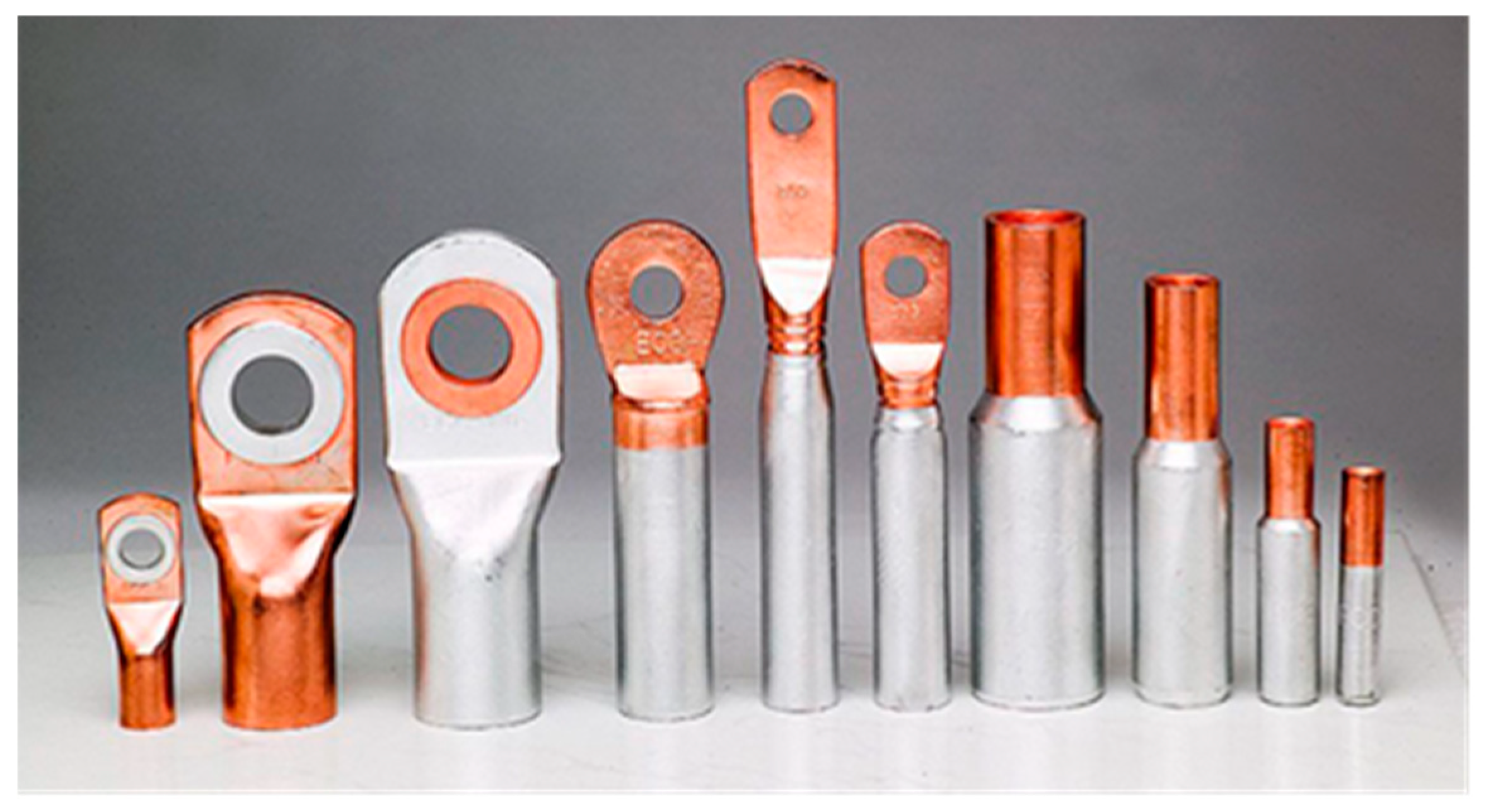
Figure 2.
(a) Friction stir welding scheme; (b) Executed joint with extruded material (Al) - “mushroom”.
Figure 2.
(a) Friction stir welding scheme; (b) Executed joint with extruded material (Al) - “mushroom”.
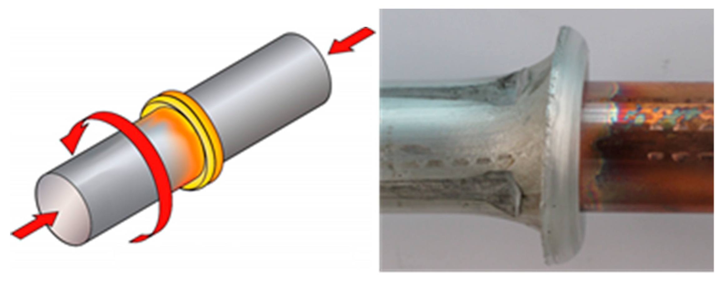
Figure 3.
(a) Appearance of the friction-welded samples as a function of the friction time; (b) friction-welded joints after the machining.
Figure 3.
(a) Appearance of the friction-welded samples as a function of the friction time; (b) friction-welded joints after the machining.
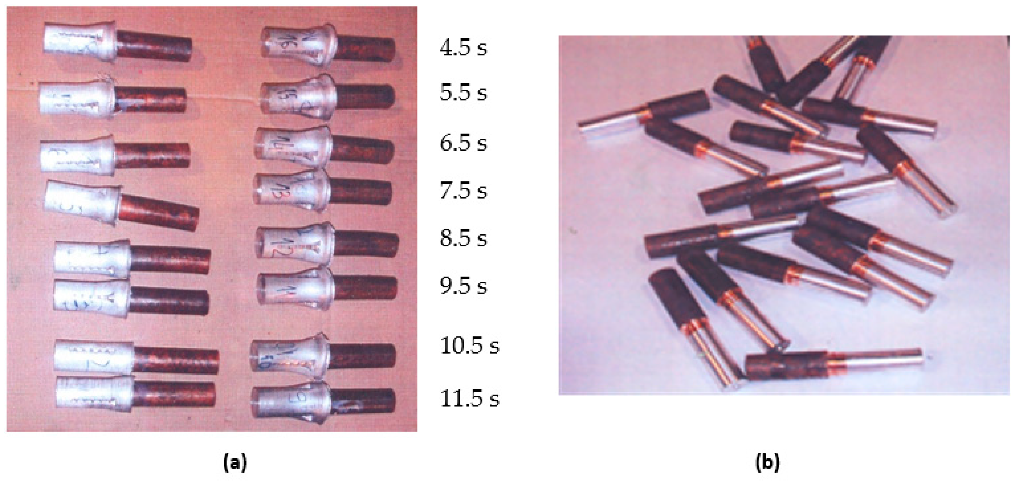
Figure 4.
The shortening of samples as a function of the friction time.

Figure 5.
Crown diameter (dv) dependence on the welding time.
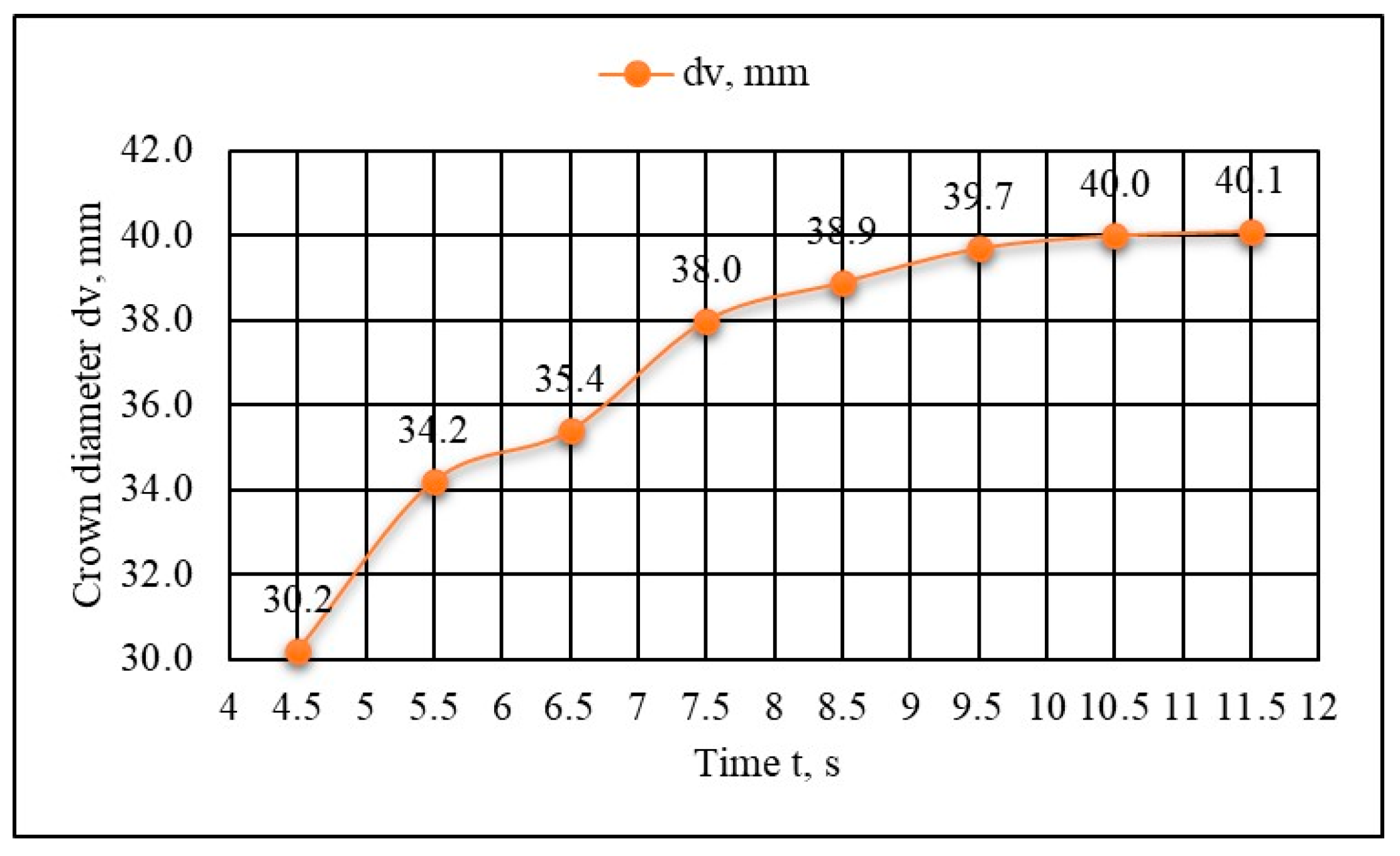
Figure 6.
Al-Cu joint samples for microstructural investigations. Friction times (left to right: 6.5, 7.5, 9.5 s).
Figure 6.
Al-Cu joint samples for microstructural investigations. Friction times (left to right: 6.5, 7.5, 9.5 s).
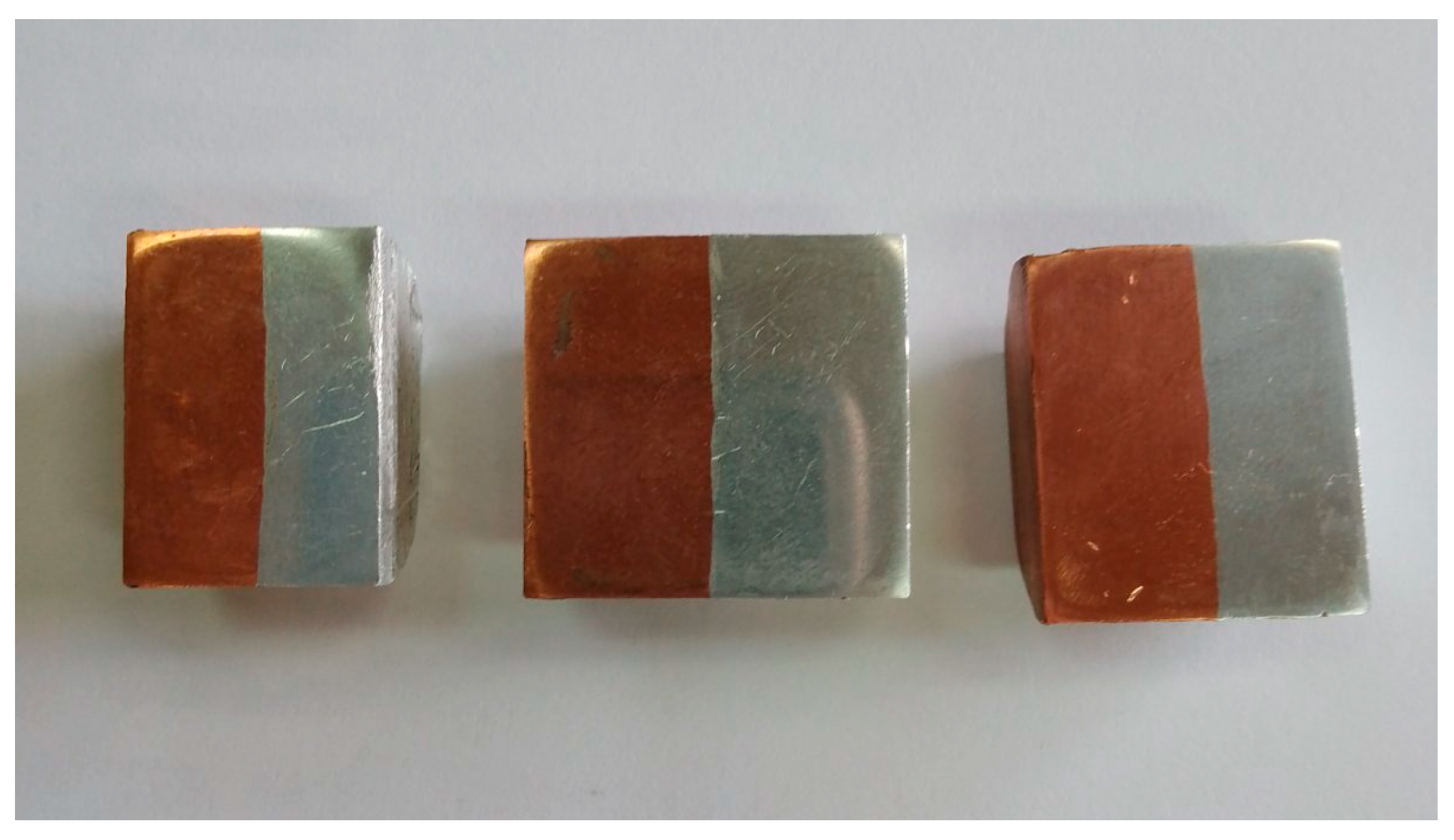
Figure 7.
Microstructure of (a) copper; (b) aluminum. The microstructure of the joint zone is presented in Figure 8, for different welding times (6.5, 7.5, 9.5 s).
Figure 7.
Microstructure of (a) copper; (b) aluminum. The microstructure of the joint zone is presented in Figure 8, for different welding times (6.5, 7.5, 9.5 s).
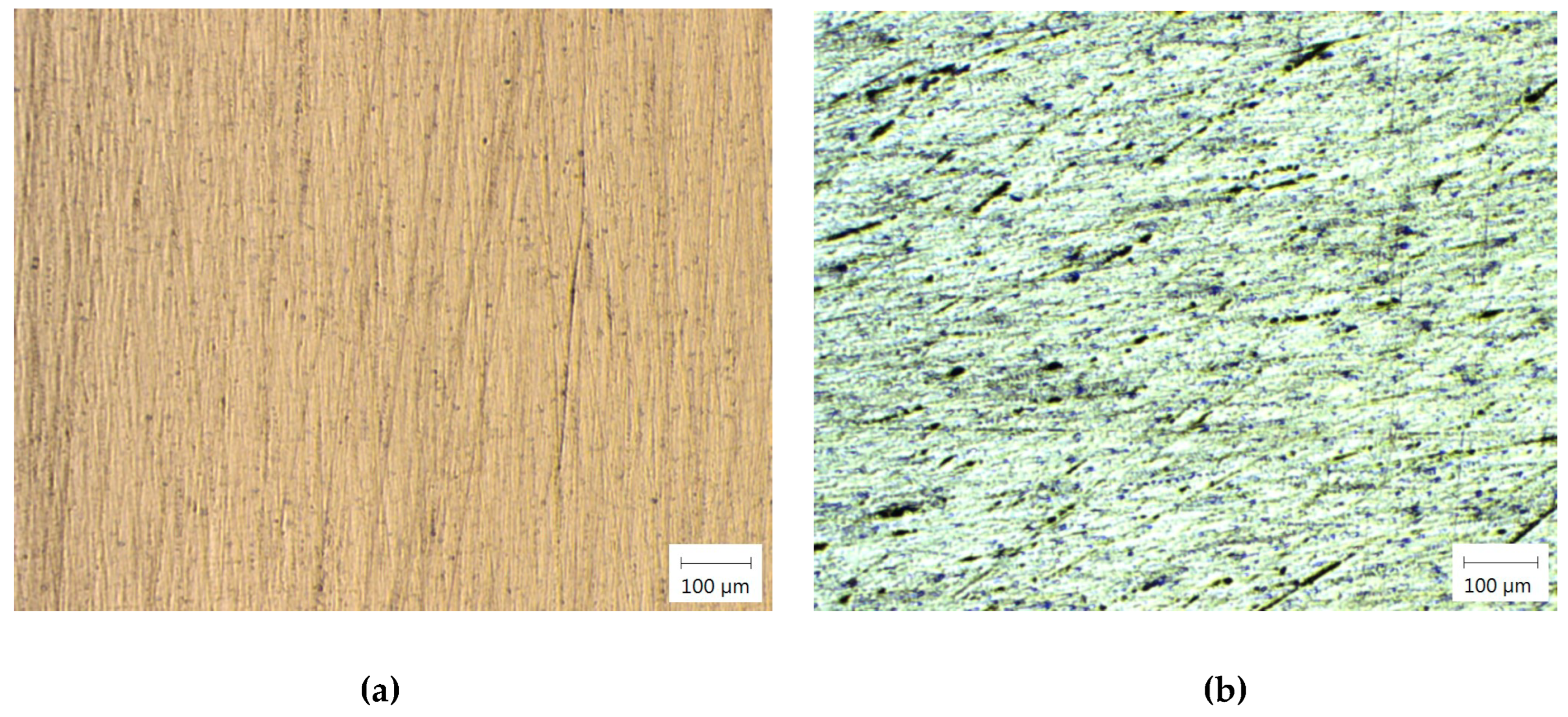
Figure 8.
Microstructure of the Al-Cu joint zone: (a) friction time 7.5 s; (b) and (c) friction time 9.5 s; (d) friction time 6.5 s.
Figure 8.
Microstructure of the Al-Cu joint zone: (a) friction time 7.5 s; (b) and (c) friction time 9.5 s; (d) friction time 6.5 s.
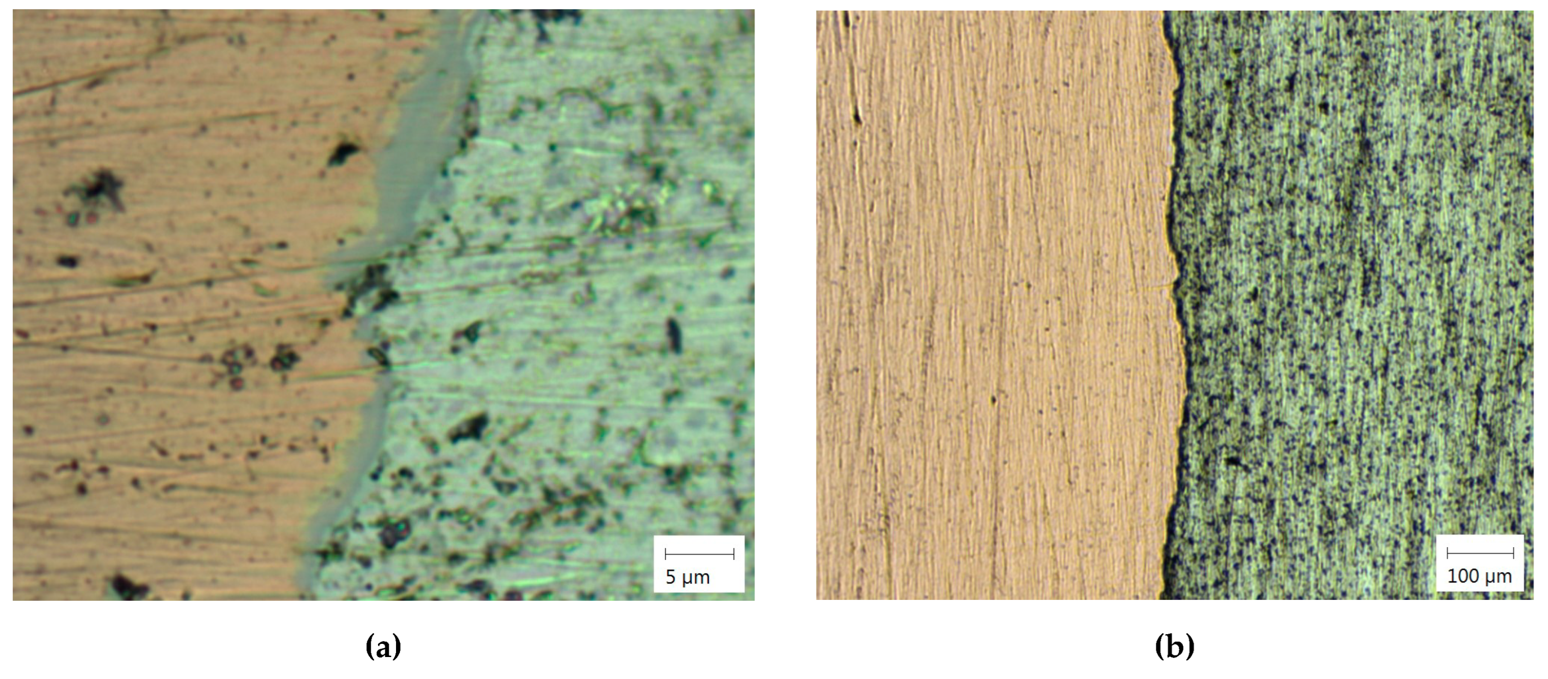
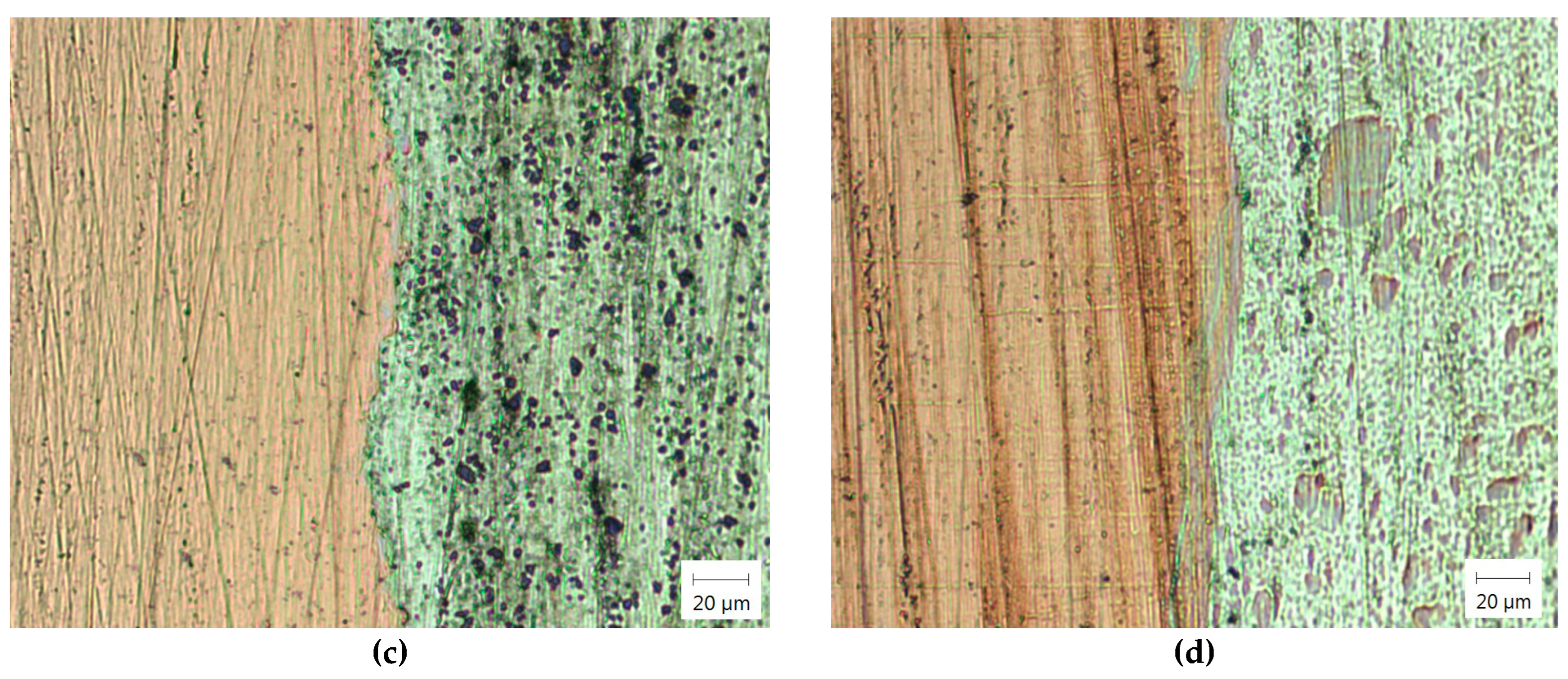
Figure 9.
Numerical simulation results (4.5 s): (a) the effective plastic strain; (b) the effective stress; (c) the workpiece temperature; (d) the cross-section temperature.
Figure 9.
Numerical simulation results (4.5 s): (a) the effective plastic strain; (b) the effective stress; (c) the workpiece temperature; (d) the cross-section temperature.
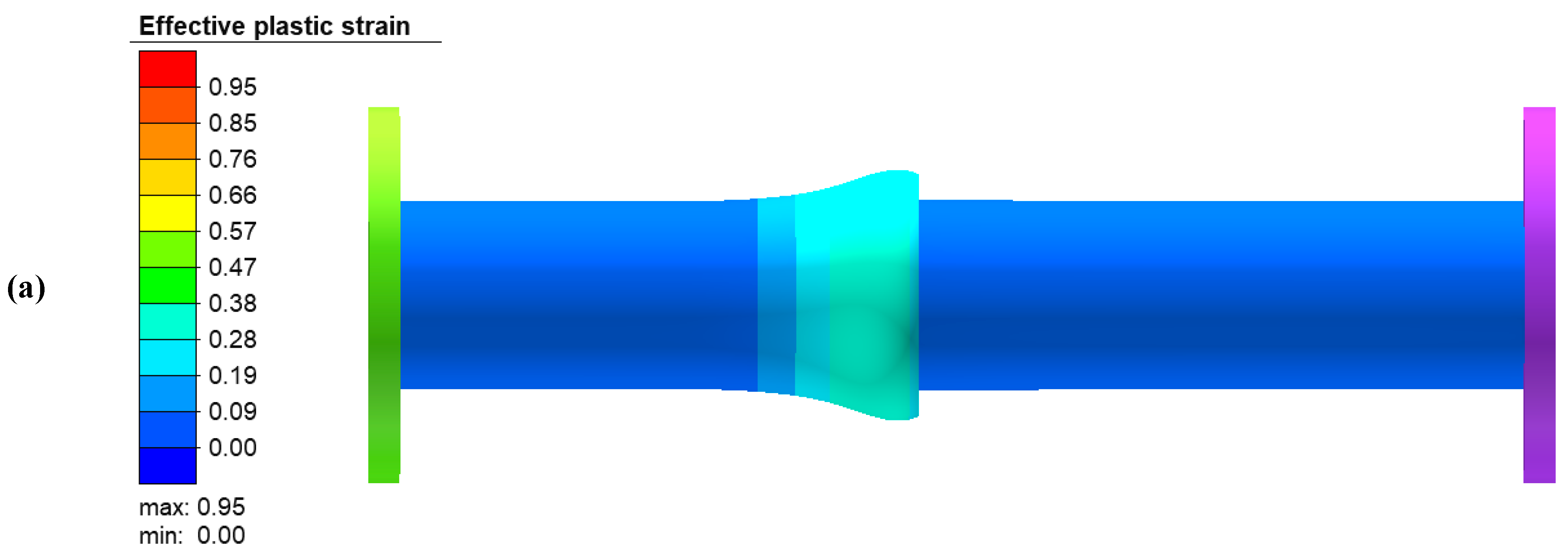
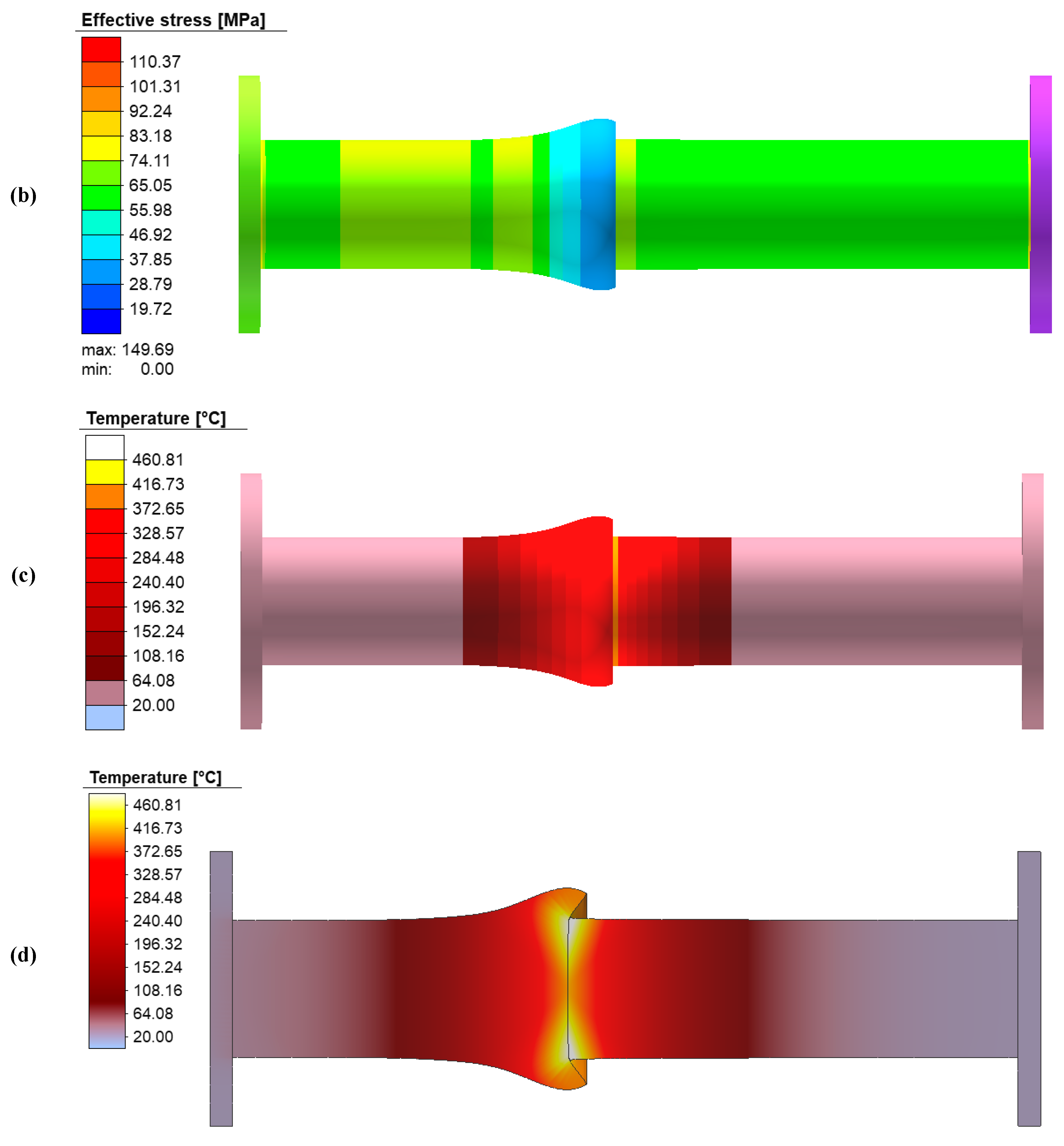

Table 1.
Measurement results of the dimensional changes in samples after the friction welding.
| Friction time | Dimensions after the friction welding | ||||||
|---|---|---|---|---|---|---|---|
| t, s | L1, mm | ΔL1, mm | ΔL1t, mm | ΔL1t, % | dv, mm | ||
| Al | Cu | Al | Cu | ||||
| 4.5 | 80.5 | 98.8 | 9.5 | 1.2 | 10.7 | 5.6 | 30.2 |
| 5.5 | 79.2 | 98.3 | 10.8 | 1.7 | 12.5 | 6.5 | 34.2 |
| 6.5 | 77.4 | 98.2 | 12.6 | 1.8 | 14.4 | 7.6 | 35.4 |
| 7.5 | 77.5 | 98.5 | 12.5 | 1.5 | 14 | 7.4 | 38 |
| 8.5 | 76.8 | 97.3 | 13.2 | 2.7 | 15.9 | 8.3 | 38.9 |
| 9.5 | 74.1 | 96.4 | 15.9 | 3.6 | 19.5 | 10.2 | 39.7 |
| 10.5 | 74 | 97.2 | 16 | 2.8 | 18.8 | 9.8 | 40 |
| 11.5 | 73.8 | 96.3 | 16.2 | 3.7 | 19.9 | 10.4 | 40.1 |
Table 2.
Hardness distribution along the axis of the sample for a friction time of 9.5 s.
| Cu | Al | |||||||||||
|---|---|---|---|---|---|---|---|---|---|---|---|---|
| Hardness, HV10 | 83.8 | 84 | 71 | 62.7 | 64 | 48.2 | 43.2 | 40 | 31.2 | 30.3 | 30 | |
| Distance from the joint line, mm | -5 | -4 | -3 | -2 | -1 | 0 | 1 | 2 | 3 | 4 | 5 | |
Table 3.
Simulation parameters.
| Parameter | Value |
|---|---|
| Simulation type | 2D |
| Mesher | Aluminum specimen - Advancing front quad Copper specimen - Quadtree |
| Finite element type and dimension | Aluminum specimen: Quads (10) – 0.3 mm Element count: 16548 Copper specimen: Quads (10) – 0.3 mm Element count: 23200 |
| Friction | Coulomb µ = 0.1 |
Table 4.
Comparison of experimental and numerical results on welded parts dimensions, mm.
| Friction time, s | Experimental results | Numerical results | Temperature (numerical simulation), °C | ||
|---|---|---|---|---|---|
| Al | Cu | Al | Cu | ||
| 4.5 | 80.50 | 98.80 | 80.54 | 98.77 | 460 |
| 7.5 | 77.50 | 98.50 | 77.71 | 88.36 | 484 |
| 11.5 | 73.80 | 96.30 | 73.59 | 98.30 | 522 |
Disclaimer/Publisher’s Note: The statements, opinions and data contained in all publications are solely those of the individual author(s) and contributor(s) and not of MDPI and/or the editor(s). MDPI and/or the editor(s) disclaim responsibility for any injury to people or property resulting from any ideas, methods, instructions or products referred to in the content. |
© 2025 by the authors. Licensee MDPI, Basel, Switzerland. This article is an open access article distributed under the terms and conditions of the Creative Commons Attribution (CC BY) license (http://creativecommons.org/licenses/by/4.0/).
Copyright: This open access article is published under a Creative Commons CC BY 4.0 license, which permit the free download, distribution, and reuse, provided that the author and preprint are cited in any reuse.


