Submitted:
28 August 2024
Posted:
29 August 2024
You are already at the latest version
Abstract
Solid-phase joining is a technique used to fuse two materials by applying heat and pressure, causing plastic deformation without reaching the melting point. This method is applicable for similar and dissimilar materials, including metals, polymers, and ceramics, without the need for filler material. Among the various methods, Friction Stir Welding (FSW) is preferred for joining dissimilar materials due to its solid-state process, which enhances mechanical properties, metallurgical compatibility, and reduces distortion. FSW is particularly effective for materials with significant differences in melting points. The current project focuses on assessing the strength and mechanical properties of FSW joints between aluminum and polymer-based composites. FSW was selected for its ability to produce fine-grained, strong welds free from fusion-related defects such as porosity and cracks. Applications in sectors like automotive, aerospace, and shipbuilding are explored, with impact, hardness, and tensile tests conducted to evaluate joint performance. This comprehensive study includes literature review, fabrication, testing, and tool design to ensure a thorough understanding of dissimilar joint properties.
Keywords:
FSW (Friction Stir Welding)
; IMc (Intermetallic Compounds)
; UTM (Universal Testing Machine)
; RPM (Revolutions Per Minute)
; HAZ (Heat Affected Zone)
; WZ (Weld Zone)
; BM (Base Metal)
; CNC (Computer Numeric Control)
; EDM (Electrical Discharge Machine)
1. Introduction
Materials integration is a crucial aspect of modern manufacturing, enabling the assembly of goods, devices, and structures by joining various components. The selection of appropriate joining techniques, such as adhesive bonding, brazing, soldering, riveting, and welding, is fundamental to ensuring the reliability and performance of the final product. Among these methods, solid-phase joining has emerged as a particularly effective technique, especially for materials that have high melting points, are susceptible to heat damage, or possess different thermal properties. Solid-phase joining unites materials by heating them to just below their melting point, inducing plastic deformation, and applying pressure to create a strong bond. This method is unique because it does not require any filler materials, making it ideal for applications where material purity and structural integrity are critical. Techniques such as friction welding, diffusion bonding, and ultrasonic welding fall under the umbrella of solid-phase joining and are especially advantageous for combining metals, ceramics, and polymers. These methods enhance joint strength, reduce distortion, and offer other benefits over traditional welding techniques
Among these methods, Friction Stir Welding (FSW) has gained prominence for its ability to join dissimilar materials, particularly those with significantly different melting points. Developed in 1991 by The Welding Institute (TWI) in the United Kingdom, FSW was initially used for joining aluminum alloys, but its application has since expanded to include a wide range of materials, including polymers and other metals. The FSW process involves a non-consumable tool that is harder than the materials being welded. This tool rotates and moves along the joint line, generating heat through friction. The heat softens the materials without melting them, allowing them to mix and bond under the pressure applied by the tool. As the tool moves along the joint, it stirs the materials together, creating a fine-grained structure with superior mechanical properties. FSW offers numerous advantages over traditional fusion welding methods, particularly the absence of melting, which eliminates common fusion welding defects such as porosity and solidification cracks. The result is welds with excellent mechanical characteristics, including enhanced strength and durability. FSW also produces minimal distortion and reduces residual stresses, which are common challenges in welding processes involving high temperatures. The process is highly versatile, capable of welding complex shapes and thick plates, making it suitable for a wide range of industrial applications. The environmental benefits of FSW are also significant. The process does not require filler materials or shielding gases, typically used in fusion welding to protect the weld from atmospheric contamination. This not only reduces material costs but also minimizes the environmental impact of the welding process by eliminating the need for consumables and reducing waste. Additionally, FSW operates at lower temperatures than fusion welding, further reducing energy consumption and the associated environmental footprint.
FSW is particularly relevant in industries that require high-strength, lightweight components, such as automotive, aerospace, and marine sectors. In these industries, the ability to join dissimilar materials, such as aluminum and polymer-based composites, is increasingly important. These materials offer a combination of low weight, high strength, and corrosion resistance, making them ideal for applications where performance and efficiency are critical. For instance, in the automotive industry, reducing vehicle weight is key to improving fuel efficiency and reducing emissions. Similarly, lightweight materials are essential in the aerospace industry for maximizing payload capacity and reducing fuel consumption. Despite its advantages, FSW of dissimilar materials presents several challenges, particularly in selecting the appropriate tool design and welding parameters. The success of the weld depends on generating sufficient heat to soften the materials without causing excessive deformation or damage. The tool must withstand the high temperatures and forces involved in the process while ensuring effective material mixing and bonding. Additionally, process parameters such as tool rotation speed, feed rate, and plunge depth must be carefully optimized to achieve the desired weld quality. This study focuses on applying FSW to join aluminum 6061 with polymer-based composites, specifically Acrylonitrile Butadiene Styrene (ABS) reinforced with carbon fibers. By evaluating the mechanical properties of these joints and optimizing the process parameters, this research aims to advance the use of FSW in creating robust, reliable connections between dissimilar materials. The findings have significant implications for industries requiring lightweight, high-performance materials, contributing to the ongoing development of efficient and sustainable manufacturing technologies.
1.1. Problem Statement
Friction Stir Welding (FSW) is a solid-phase joining technique that unites dissimilar materials, such as aluminum and polymer composites, without melting. This process enhances joint strength, reduces defects, and is vital in industries like automotive and aerospace for creating lightweight, durable components.
1.2. Objective
- The following are the objectives of our project:
- To evaluate the feasibility and effectiveness of Friction Stir Welding (FSW) for joining dissimilar materials.
- To fabricate polymer-based composite plates using injection molding and thermal press machines.
- To conduct mechanical characterization of the samples through various experiments.
- To optimize process parameters for achieving strong welds with metallurgical compatibility, enhanced material mixing, and minimal defects.
2. Literature Review
2.1. Background of FSW of Dissimilar Materials
After twenty years of advancement, FSW has evolved into a practical and significant manufacturing alternative, particularly in the realm of aerospace and aeronautics applications, particularly those involving aluminum alloys.[4,5] . While FSW initially emerged as an alternative for joining aluminum alloys, its evolution has expanded to encompass higher temperature systems. This includes the application of FSW to materials such as stainless steels, titanium, and titanium alloys [6] . There has been a growing interest in employing FSW for dissimilar metals and alloys, especially in cases where conventional thermal (or fusion) welding methods face challenges or prove impossible. This extends to the welding of metals with polymer-based composite materials. The process of joining similar or dissimilar materials and alloys in FSW relies on intense deformation, leading to dynamic recrystallization (DRX). This phenomenon enables solid-state flow through sliding between recrystallized, equated, and typically submicron grains within the weld zone [7,8].
The welding parameters, which directly affect the heat input, are critical to the effective creation of sound friction stir welded (FSW) joints in the Al-steel system [9] . On the other hand, a greater tool offset, and faster rotating speed can cause the weld's total temperature distribution to rise. As a result, these variables may affect the Intermetallic Compound (IMC) layer's composition.[10]. Analogous research has been carried out for systems involving polymers and dissimilar metal combinations, like aluminum and steel. The goal of these investigations is to maximize the strength of the welded joints by optimizing friction stir welding parameters. [11,12].
2.2. Exploring Lightweight Design in Automotive and Aerospace Industries
Furthermore, the implementation of lightweight structures is a pivotal design consideration in high-tech industries like automotive and aerospace. This emphasis on light weighting aims to diminish fuel consumption and enhance overall energy efficiency [13]. A critical aspect involves the incorporation and utilization of non-metallic materials, such.as polymers, alongside metallic components [14]. In this scenario, there has been recent development in metal-polymer hybrid systems, generating considerable interest for real-world applications, especially in the automotive sector [15] . An upcoming concept car slated for release in 2025, named F-125, is currently under construction by Mercedes-Benz. This innovative vehicle is designed to be composed of metal-polymer hybrids, aiming to minimize emissions. The manufacturing process involves extensive use of mechanical fastening to create intricate hybrid structures combining metals and polymers.[16]. Because of this, the idea of creating permanent hybrid materials by directly combining different metals and polymers has emerged as a significant engineering issue. This is especially remarkable because of the substantial metallurgical difficulties resulting from the marked differences between these various materials[17]. The adoption of fusion-based welding technologies, like laser welding, which entail the melting and solidification of metals and polymers within the weld nugget, faced challenges and proved unsuccessful. This was primarily due to excessive loss of polymeric material and metallurgical incompatibility between the metals and polymers, hindering the formation of a perfect chemical bonding at the interface. [15,18] . As a result, the research focus in this field Shifted towards the utilization of solid-state welding technologies, particularly those based on ultrasonic vibration, friction stir welding (FSW) is acknowledged as an advanced solid-state joining technology that integrates the principles of frictional heating and severe plastic deformation (SPD). This thermo-mechanical process involves the plasticization of metallic materials, followed by subsequent mixing and consolidation, all conducted below the melting temperature of the processed materials. To achieve this state, a non-consumable rotating tool is commonly employed, forging into the material's surface to induce softening. Subsequently, by traversing along the specified direction, a solid-state joint line between similar or dissimilar materials can be formed through the intense mixing and operation of related metallurgical transformations.
2.3. Selection of Material and Durability of FSW Tool
Moreover, it is important to remember that the high temperatures reached during the process—typically between 1000 and 1200 °C—restrict the choice of material that may be used to manufacture the tool. Making sure the tool is immune to degradation acts like wear, deformations, microstructural instability, fracture, or reactivity with the material that makes up the workpiece is an essential requirement for the effective completion of the welding process. Most people agree that the tool is the most important element in creating a very effective, flawless joint. [19] . Refractory alloys derived from the tungsten-rhenium system find extensive use in steel processing. In a study by Almoussavi et al., the wear of polycrystalline cubic boron nitride (PCBN) in friction stir welding (FSW) tools was investigated both experimentally and numerically. The findings revealed that the tool's shoulder periphery and the bottom side of the probe are particularly susceptible, experiencing notable wear issues. [20] As corroborated by Soresen et al., the use.of polycrystalline cubic boron nitride (PCBN) tools in friction stir welding (FSW) of ferrous alloys results in a high-quality finish. [19].
2.4. Innovations in Friction Stir Welding for Thermoplastic Polymer-Metal Joining
Certainly! "Light weighting Trends in the Automotive Industry," is crucial for setting the context of why weight reduction has become a prime objective in the automotive sector and why innovative welding processes like Friction Stir Welding (FSW) are gaining attention. By reducing the weight of a vehicle, the overall performance of the vehicle would be improved and fuel consumption would be decreased. For this reason, choosing the composites with aluminum would be the perfect pair for reducing the weight. For joining these materials Friction stir welding is the best option for the industrialist.
The successful joining of thermoplastic polymer and metal through Friction Stir Welding (FSW) is explored in the article "Friction stir welding/processing of polymers and polymer matrix composites" by Xiangchen Meng et al. However, challenges such as the occurrence of bubbles, degradation, and gaps at the interface of metal and polymer may diminish the load-bearing capacity..[21] but now we will use polymer base composite instead of polymer with metal which will increase the weld strength and no bubble formation. [22].
3. Materials and Methods
This study focuses on Friction Stir Welding (FSW) of polymer-based composites, specifically Acrylonitrile Butadiene Styrene (ABS) as the polymer matrix, reinforced with carbon fibers, and Aluminum 6061 as the metal counterpart. This combination was selected due to its relevance in industries such as automotive, marine, and aerospace, where lightweight and durable materials are essential.
- 1.
- Aluminum 6061:
Aluminum 6061-T6 was chosen as the foundation metal due to several key properties:
- Lightweight: In the automotive industry, reducing vehicle weight is a primary goal for improving fuel efficiency and overall performance. FSW with aluminum and polymer composites supports this objective by enabling the production of lightweight, strong structures.
- Compatibility with Polymer Composites: Aluminum’s compatibility with ABS in FSW allows for the creation of robust joints without compromising mechanical properties. The solid-state nature of FSW minimizes heat input, preserving the integrity of both materials, resulting in hybrid structures with enhanced stiffness and impact resistance.
- Corrosion Resistance: Aluminum naturally forms an oxide layer that provides excellent corrosion resistance, making it ideal for use in harsh environments, such as those encountered in the automotive industry. This resistance is also beneficial when welding with ABS using FSW.
- Industry Adoption: Aluminum is widely used across various industries due to its extensive research, development, and successful application in numerous products, particularly in automotive light-weighting initiatives. Its proven performance in FSW applications further underscores its suitability for joining with polymer-based composites.
Material Specifications: For this study, Aluminum 6061-T6 plates and polymer-based composite plates, each with dimensions of 100mm x 100mm x 3mm, were used. These materials were selected based on their compatibility and performance in FSW applications.

Table 1.
Classes of Alumnium Alloys.
| Serial Number | Alloying Element |
Alloy Category |
Typical Applications |
|---|---|---|---|
| 1xxx |
Aluminum |
Commercially Pure | Power Grid, Transmission and Electrical. |
| 2xxx. | Copper | .Heat Treatable | Piston, Aircraft & Cylinder |
| 3xxx. |
Manganese. |
Non-Heat Treatable | Beverage cans and Cooking Utensils |
| 4xxx |
Silicon |
.Non-Heat Treatable | Automotive. And Structural. |
| 5xxx |
Magnesium. |
Non-Heat Treatable | Marine, Pressure Vessels and Storage Tanks |
| 6xxx |
Magnesium and Silicon | Heat Treatable | Automotive and Structural |
| 7xxx | Zinc | .Heat Treatable | Aircraft |
Composition of Al alloy 6061-T6:
Table 2.
Chemical Composition of Al alloy 6061-T6.
| Elements | Al | Mg. | Si. | Cr.. | Mn. | Ti. | Cu.. | Zn. | Fe.. | .Others. |
| Wt. (%) |
.Bal |
0.82-1.25 |
0.42-0.82 |
0.05-0.46 |
0.161 |
0.171 |
0.16-0.42 |
0.255 |
0.72 |
0.145 |
Aluminum 6061-T6 is primarily composed of aluminum, with added elements such as silicon, iron, copper, magnesium, zinc, chromium, and titanium to enhance its properties. These additions improve the alloy's strength, hardness, corrosion resistance, and machinability. The alloy offers a balanced combination of strength, ductility, and durability, making it ideal for various applications, especially in industries requiring high performance and reliability.
- 2.
- Polymer based composite plate:
In this project of polymer-based composite plates is used, specifically thermoplastic polymers, as the matrix material for Friction Stir Welding (FSW) with aluminum 6061. The resin systems used in advanced composites are primarily categorized into two types:
- Thermosetting polymers.
- thermoplastic polymers.
Thermosetting polymers undergo an irreversible chemical reaction during curing, transforming from a liquid or soft state to a hardened state. Once cured, these materials cannot be re-melted or reshaped, which limits their recyclability. Common examples of thermosetting resins include epoxy, phenolic, and vinyl ester resins.
| Polymer | Melting Point (°C) | Glass Transition Temperature (°C) | Thermal Conductivity (W/m·K) | Tensile Strength (MPa) |
| Polypropylene (PP) | 135-165 | -10 | (0.17 - 0.25) | 31-41 |
| High-density polyethylene (HDPE) | 110-135 | -95 | 0.4-0.49 | 25-40 |
| Ultra-high-molecular-weight polyethylene (UHMWPE) | 130-140 | -80 | 0.41 | 80-150 |
| Acrylonitrile butadiene styrene (ABS) | 200-230 | 105 | 0.18-0.25 | 40-70 |
| Polycarbonate (PC) | 240-260 | 150 | 0.19-0.25 | 60-70 |
| Polyether ether ketone (PEEK) | 340-345 | 143 | 0.25-0.29 | 100-150 |
| Polyvinyl Chloride (PVC) | 170-200 | 80-100 | 0.17-0.21 | 48-55 |
For this study, thermoplastics are selected due to their recyclability, shorter processing cycles, and excellent impact resistance. Thermoplastics soften when heated, allowing them to be molded into various shapes, and solidify upon cooling—a process that is reversible, meaning these materials can be re-melted and reformed multiple times without significant degradation of their properties. This characteristic makes thermoplastics ideal for sustainable manufacturing processes.
When considering FSW of dissimilar materials with aluminum, thermoplastics like Acrylonitrile Butadiene Styrene (ABS), polyethylene (PE), polycarbonate (PC), and polyether ether ketone (PEEK) offer significant advantages. Their ability to maintain mechanical integrity during the high-temperature FSW process is crucial for creating durable joints. The thermoplastics selected for this project are evaluated based on their melting points, thermal conductivity, and tensile strength, ensuring optimal performance in FSW applications.
ABS (Acrylonitrile butadiene styrene) as a matrix:
Acrylonitrile Butadiene Styrene (ABS) is selected as the matrix material for this study due to its exceptional properties and widespread use in various industrial applications. ABS is renowned for its high strength-to-weight ratio, providing both lightweight and durable characteristics, which are crucial in industries were reducing weight without compromising strength is essential. Additionally, ABS offers excellent toughness and impact resistance, making it well-suited for applications that require materials capable of withstanding harsh conditions and mechanical stresses.
The extensive availability and proven performance of ABS in advanced manufacturing further enhance its suitability as a matrix material. Its established use in a range of industries, from consumer goods to automotive parts, underscores its reliability and effectiveness in demanding environments. The combination of versatile properties, ease of processing, cost-effectiveness, and broad availability makes ABS a preferred choice for numerous applications, including those requiring advanced manufacturing techniques such as Friction Stir Welding (FSW) with dissimilar materials like aluminum.
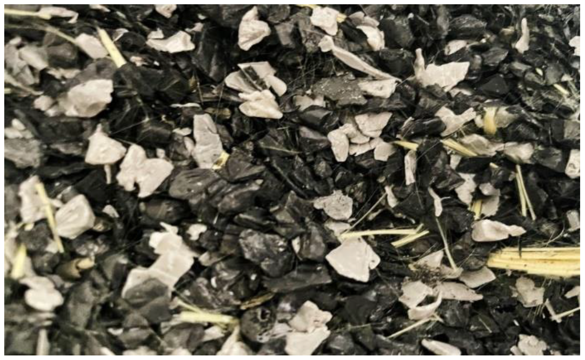
Figure 1.
Crushed Acrylonitrile butadiene styrene (ABS) polyme.
Carbon fibers as reinforcement material:
Carbon fibers are chosen for their high tensile and impact strength, excellent fatigue resistance, and lightweight properties, making them ideal for demanding applications in industries like aerospace, automotive, and marine.
Figure 2.
Chopped Carbon Fibers.

3.1. Preparation of Polymer Based Composite Plates through Thermal and Heating Press
Three feasible techniques for preparing polymer-based composites in this study are:
- Manual thermal press
- Iso-thermal hot press
- Injection molding using a material composition of 80% ABS polymer and 20% carbon fibers.
- 3.
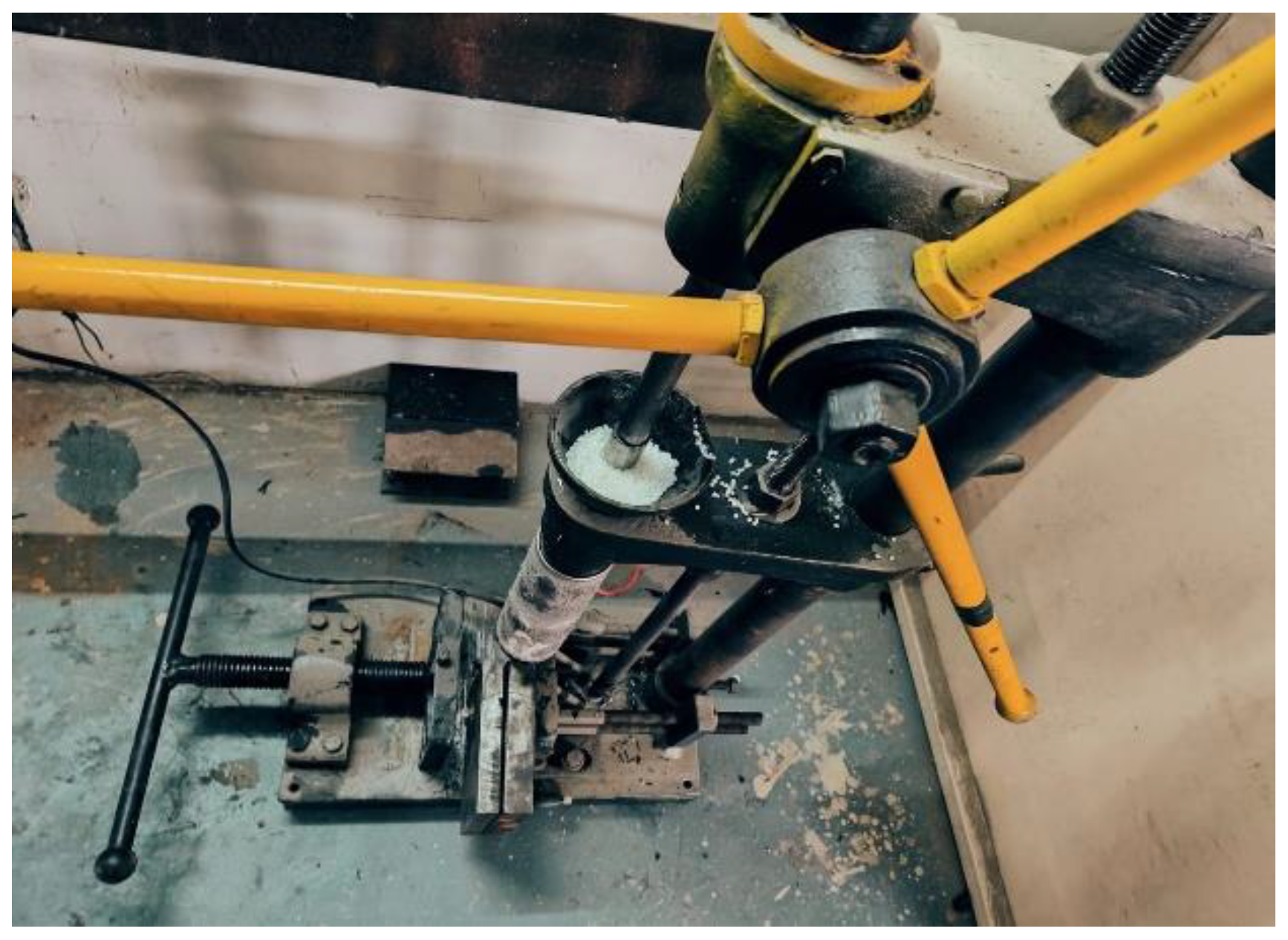
- Manual Thermal Press Machine:
The thermal press technique was initially employed to fabricate polymer-based composite plates using Acrylonitrile Butadiene Styrene (ABS) as the matrix and chopped carbon fibers as the reinforcement.
Figure 3.
Manual thermal press.
Although this method is typically used for thermosetting polymers, it was adapted in this project for thermoplastics due to available equipment.
- A mould with required dimensions was prepared to ensure uniformity.
- Acrylonitrile Butadiene Styrene (ABS) and carbon fibers were mixed in an 80:20 ratio.
- The mixture was poured into the thermal press, where it was heated to melt the materials for proper mixing.
- The molten material was pressed into the mould cavity to ensure complete filling.
- The filled mould was allowed to cool, solidifying the composite plate, which was then removed for further processing.
Figure 4.
ABS and carbon fibers through Thermal process.
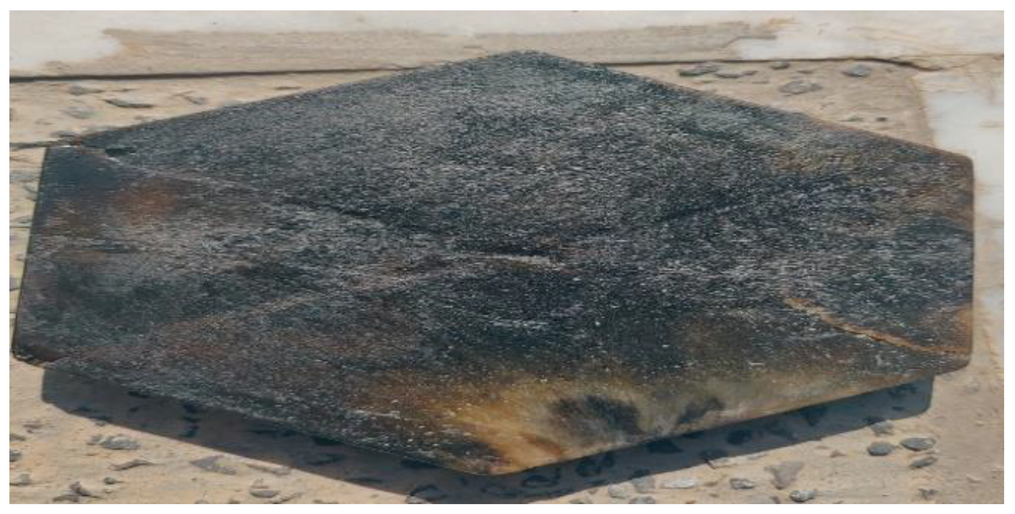
Despite following the process, several issues arose, including inadequate material flow and improper mixing of HDPE and carbon fibers, leading to defects such as cracks and uneven distribution. These defects resulted in reduced mechanical properties and localized stress concentrations, compromising the strength and integrity of the composite plates. Due to these challenges, the project shifted to using injection molding, which offers better control over material mixing and temperature, thus minimizing defects and improving the quality of the composite plates.
- 4.
- Iso-thermal Hot Press:
The iso-thermal hot press machine was utilized for the molding and lamination of composite plates, capable of operating at temperatures up to 800°C and applying up to 30 tons of pressure.
Figure 5.
Isothermal Hot Press.
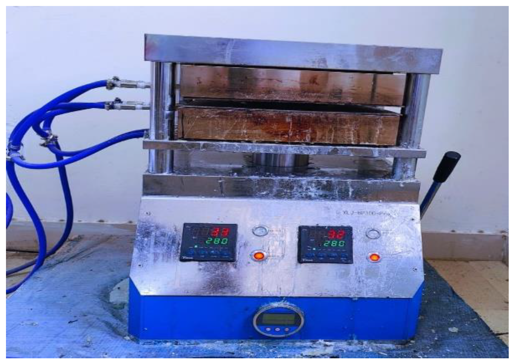
The machine consists of a fixed upper heated plate and an adjustable lower plate, which can be manually moved using a hydraulic system.
- A mild steel mould, divided into male and female parts, was prepared according to the required dimensions.
- Layers of ABS polymer and carbon fibers were alternately placed in the male part of the mould, following the specified volume ratio.
- The mould was closed by fitting the male part into the female part and placed between the heated plates of the iso-thermal hot press. The machine was set to 280°C, the melting temperature of ABS, allowing the polymer to melt and fill the mould cavity.
- After the required heating period, the mould was cooled to solidify the composite plate, which was then removed from the cavity.
Figure 6.
FSW of composite plate from Iso thermal heat press with aluminum.
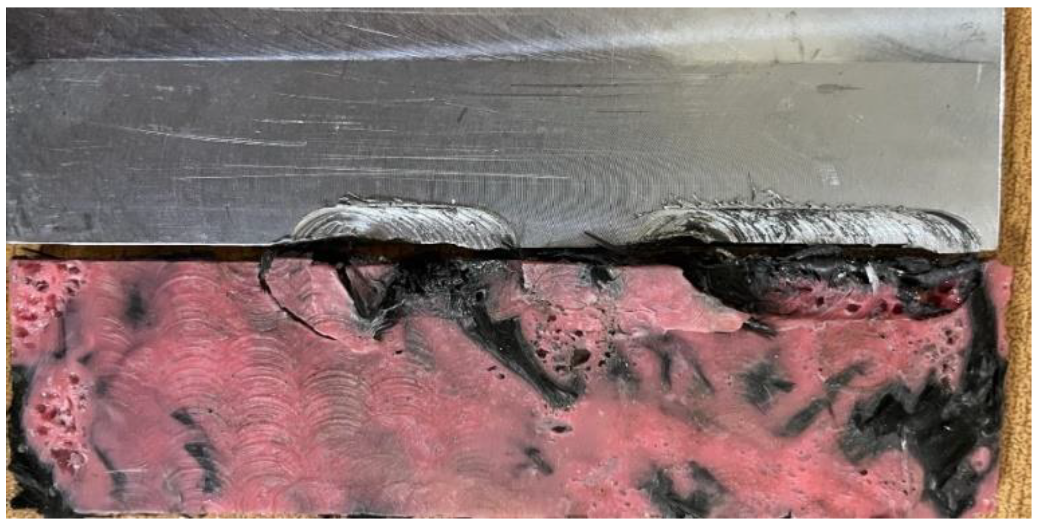
The composite plates produced using the iso-thermal hot press exhibited significant porosity and voids, which compromised the microstructure of the material. Additionally, the carbon fibers did not mix properly with the ABS polymer, making the plate difficult to weld with aluminum using Friction Stir Welding (FSW). Despite adjusting various welding parameters, successful welding was not achieved due to the poor mixing of carbon fibers, which resisted tool rotation during FSW. Given these challenges, transitioning to injection molding was deemed necessary to achieve better material flow and proper mixing of carbon fibers and ABS polymer, thereby improving the overall quality of the composite plates for successful welding with aluminum.
- 5.
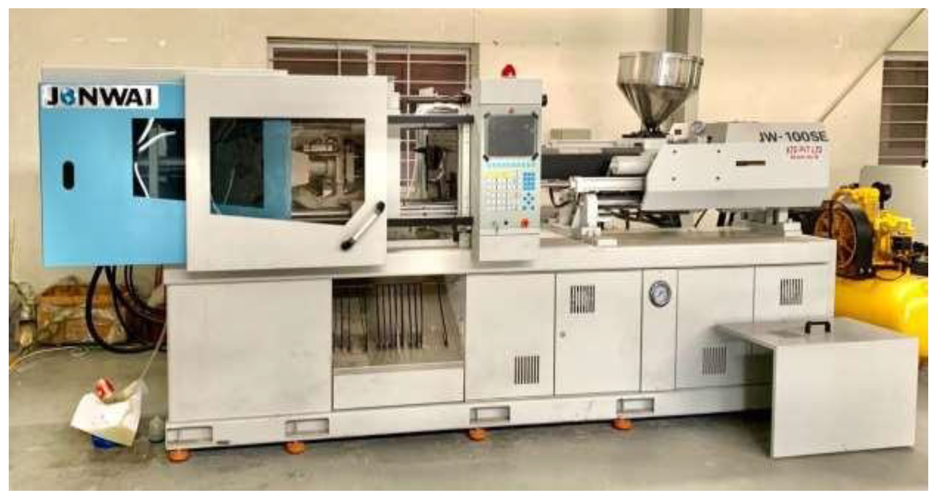
- Injection Molding Machine:
JSW-100SE Machine was used for the fabrication of samples.
Figure 7.
Injection Molding Machine.
Assembly of Injection Mold and fitting in the molding machine:
After the CNC machining of each component was completed, the injection mold was systematically assembled. Each manufactured part underwent a detailed inspection to verify dimensional accuracy, surface finish, and adherence to design specifications. An assembly process was carefully planned based on the injection mold's functional requirements and SolidWorks design guidelines. This planning included determining the optimal sequence for assembling components to ensure proper alignment and integration. The assembly process included the installation of various mold components such as ejector pins, guide pins, slides, lifters, and cooling channels, with each part being thoroughly checked for correct fit and functionality within the overall mold structure.
Figure 8.
Mild steel Blocks and D2 steel pins.
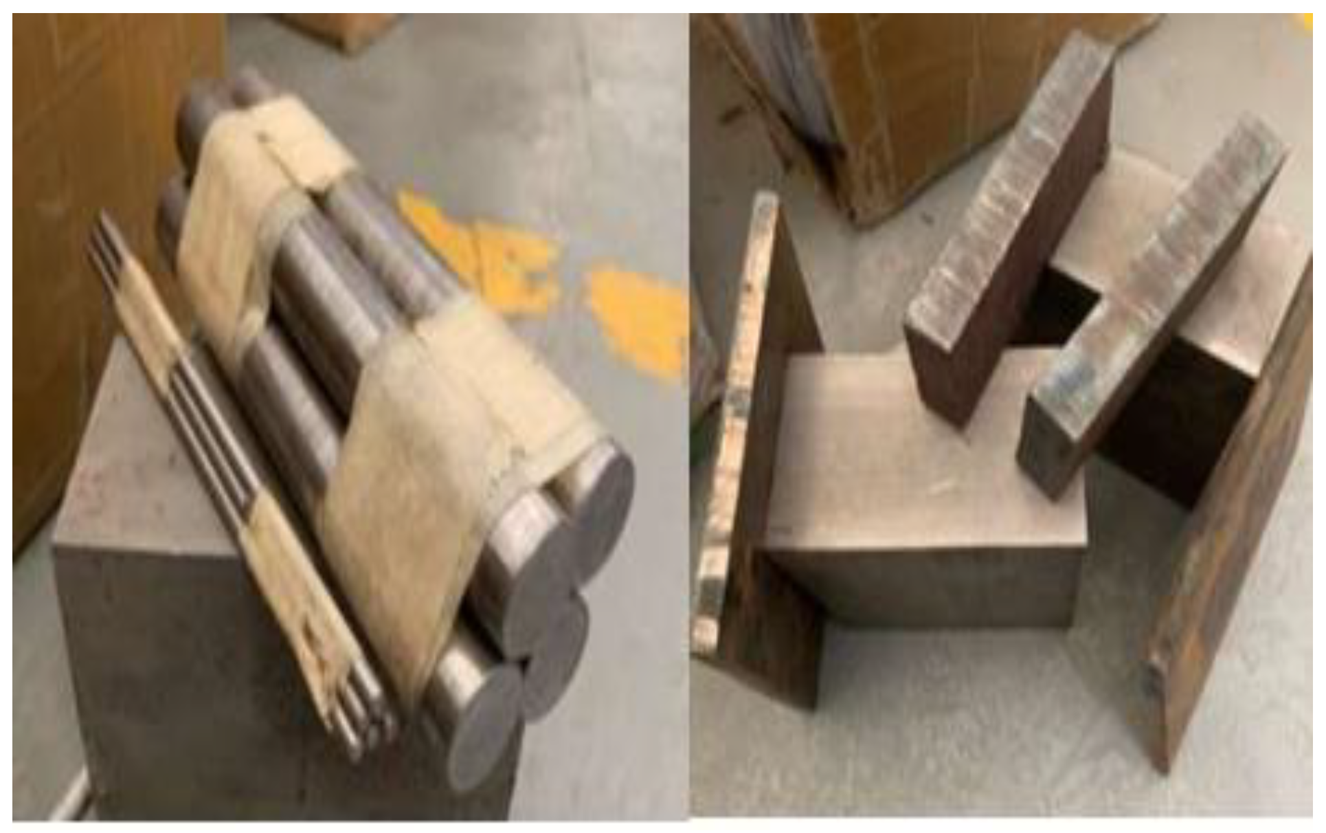
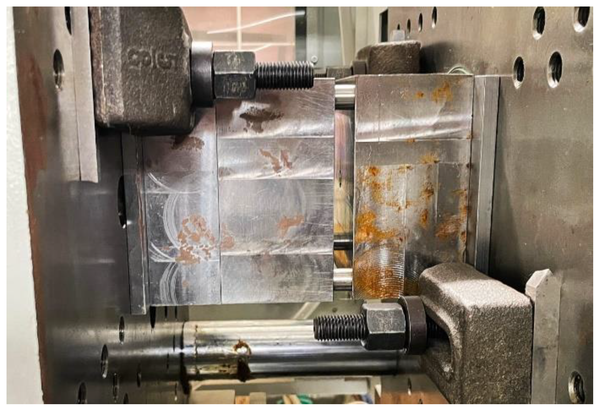
Figure 9.
Mould fitted into the injection moulding machine.
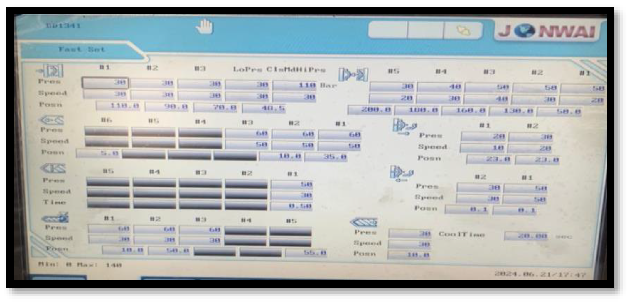
Setting of Injection Molding Machine Parameters:
Figure 10.
Parameters setting.
Formation of polymer based composite plate:
After positioning the mold in the injection molding machine, a mixture of ABS polymer and carbon fibers, in the ratio specified, was loaded into the hopper. The materials were then conveyed into a heated barrel by a rotating screw, where they were melted. The molten mixture was injected into the mold cavity by the forward movement of the screw, acting as a plunger. Once the material solidified, the mold was opened, and ejector pins pushed the molded square plate out of the cavity. This process was repeated to produce the required number of composite plates.
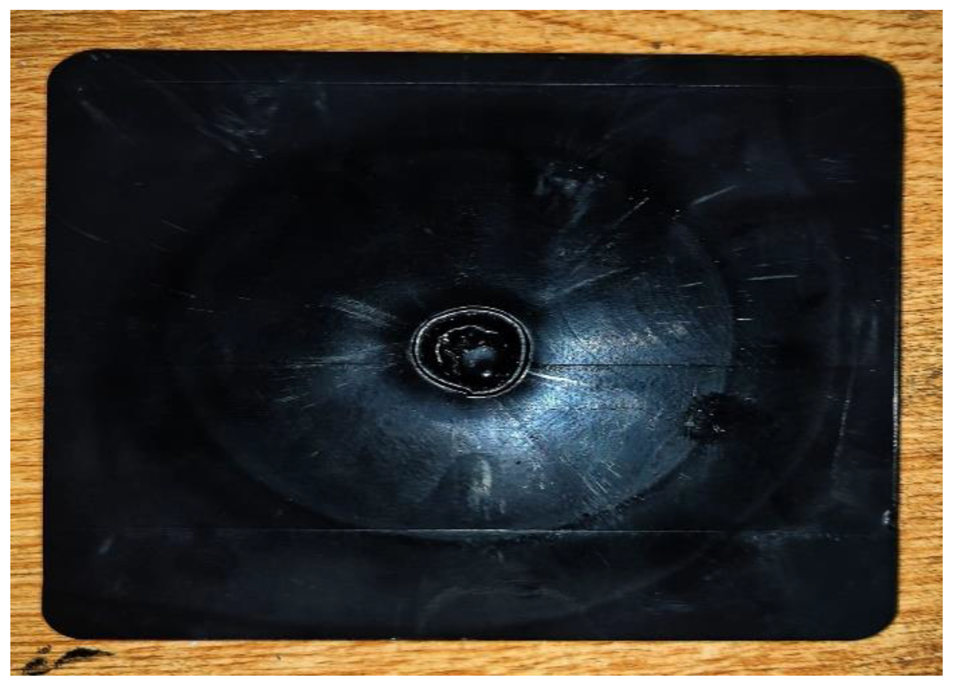
Figure 11.
Composite plate through Injection Moulding Machine.
- 6.
- Experimentation:
An H13 grade steel tool was selected for Friction Stir Welding (FSW) of the polymer-based composite plate with aluminum 6061 due to its excellent strength, toughness, and heat resistance. Known for its durability, H13 steel withstands the mechanical stresses, elevated temperatures, and abrasive forces encountered during FSW, ensuring compatibility with aluminum alloys and extending tool life. These properties make H13 an ideal choice for maintaining structural integrity and improving the overall efficiency of the welding process.
CAD model of FSW Tool.
Figure 12.
CAD model of the FSW tool.
3.2. FSW TOOL
Tool pin geometry, including threaded and tapered designs, crucially affects material flow and weld quality in FSW, enhancing mixing and reducing forces for better results.
The shoulder diameter of the tool is crucial for generating frictional heat and plasticizing the workpiece, with the ratio of shoulder to pin diameter (Ds/Dp) being key to optimizing joint properties during welding. This design maximizes heat generation and influences the overall weld quality.
The H-13 grade steel tool, used for FSW, contains carbon (0.32%-0.45%) for hardness, along with elements like silicon and iron to enhance strength, wear resistance, and high-temperature performance.
Friction Stir Welding Process Parameters:
The plate thickness for FSW was finalized at 3mm, based on estimates and tests to optimize strength and tool geometry.
Table 3.
Parameters of FSW Process.
| Samples | TOOL RPM | FEED RATE | Offset (mm) |
| S1 | 70 | 120 | 0.55 |
| S2 | 100 | 120 | 0.55 |
| S3 | 130 | 120 | 0.55 |
| S4 | 200 | 120 | 0.55 |
| S5 | 250 | 180 | 0.45 |
| S6 | 280 | 180 | 0.45 |
| S7 | 300 | 180 | 0.45 |
| S8 | 400 | 180 | 0.45 |
Keeping the plunge depth and tilt angle constant which is 2.8mm and 2.5mm respectively.
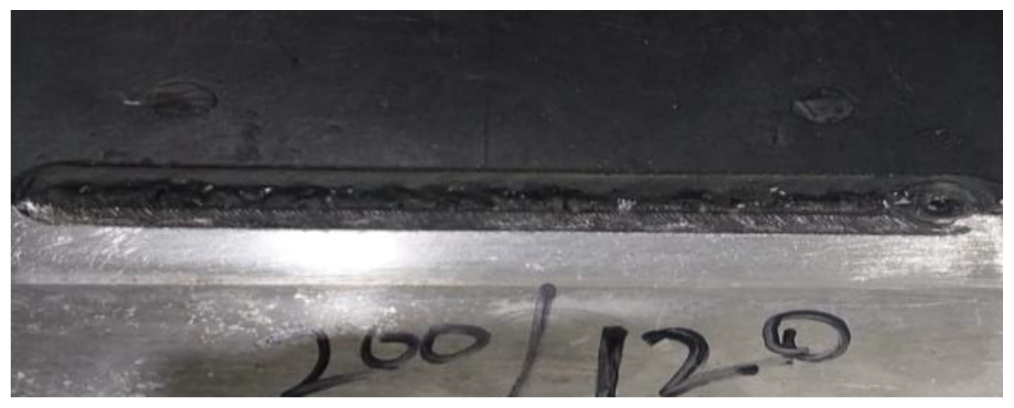
Friction stir welded Plates:
Figure 13.
FSW of Al 6061 and composite.
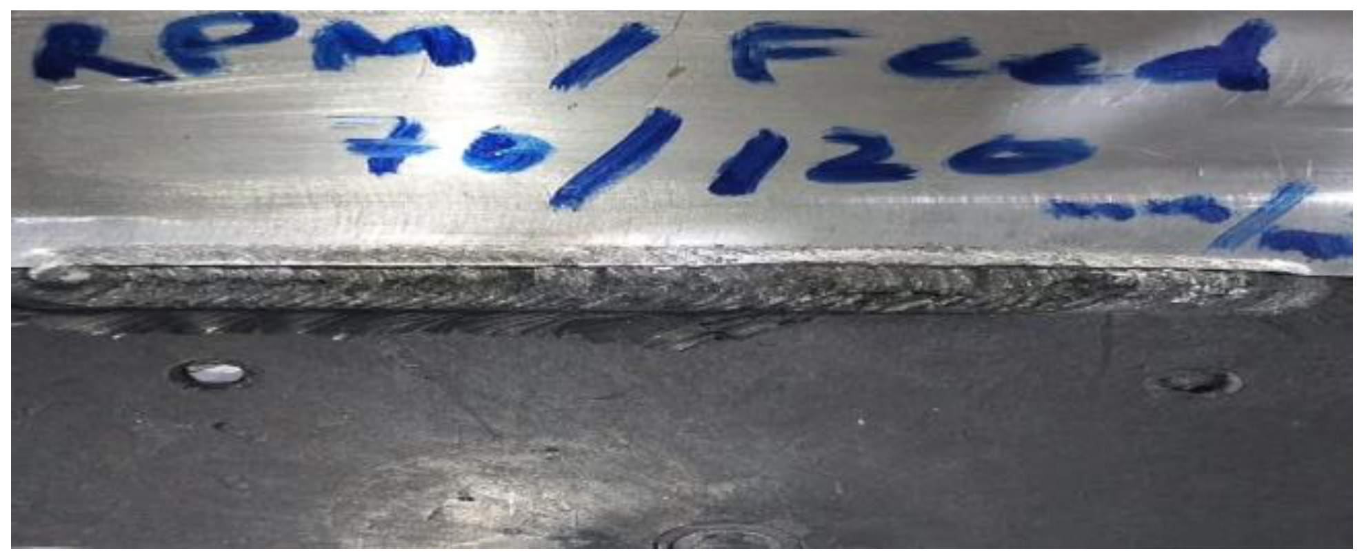
Figure 14.
FSW of Al 6061 and composite.
Friction Stir Welding of Al 6061 and Al 2029:
Given the suboptimal results from FSW of polymer-based composites with aluminum, the focus shifted to welding dissimilar aluminum alloys, namely Al 6061 and Al 2029. Al 2029 was selected for its superior strength, heat treatability, and excellent machinability, along with its high corrosion resistance, making it ideal for critical applications in the aerospace and automotive sectors.
Table 4.
Parameters OF FSW of Al 6061 and Al 2029.
| Samples | TOOL RPM | FEED RATE |
|---|---|---|
| S1 | 400 | 400 |
| S2 | 600 | 400 |
| S3 | 800 | 400 |
| S4 | 900 | 400 |
| S5 | 1000 | 400 |
| S6 | 1100 | 400 |
Keeping the plunge depth and tilt angle constant which is 2.5mm and 1.5mm respectively.
The same H13 steel tool was used for different aluminum alloys.
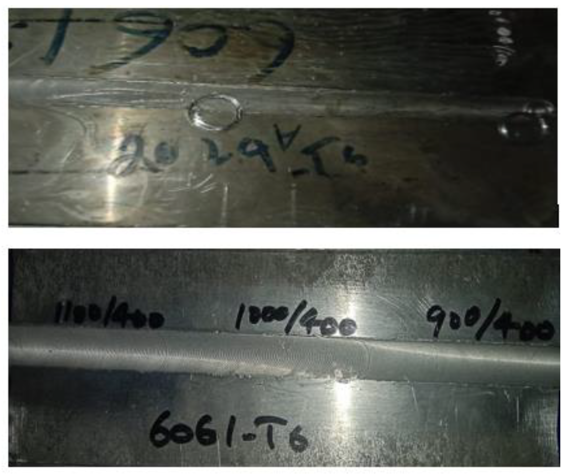
Figure 15.
FSW Plates of Al-6061 and Al-2029.
4. Simulation Analysis
Simulation is vital for optimizing Friction Stir Welding (FSW) parameters, providing insights into welding speed, tool RPM, temperature distribution, material flow, and stress-strain behavior—areas challenging to fully grasp through manual methods. ABAQUS was chosen for its accuracy and reliability in generating meaningful results.
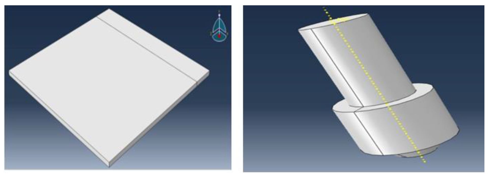
Modeling:
The simulation starts with modeling the aluminum 6061 and ABS composite plates (100mm x 100mm x 3mm) and the FSW tool, where precise tool geometry is crucial for heat generation and material flow.
Figure 16.
Design of plate and FSW tool.
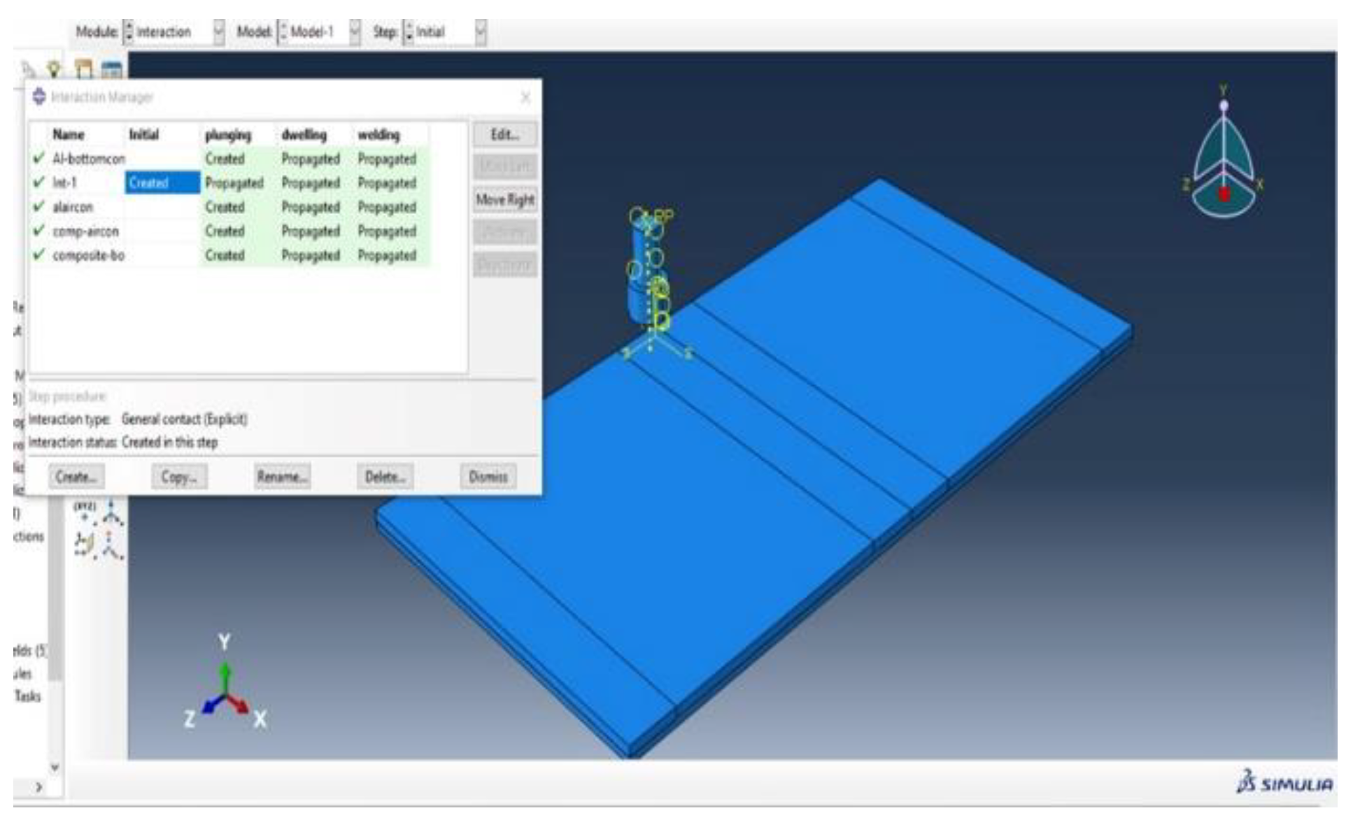
Assembly and Interaction:
The plates and tool are assembled in a realistic welding scenario, with defined mechanical and thermal interactions to simulate friction and heat generation during FSW.
Figure 17.
Assembly of system.
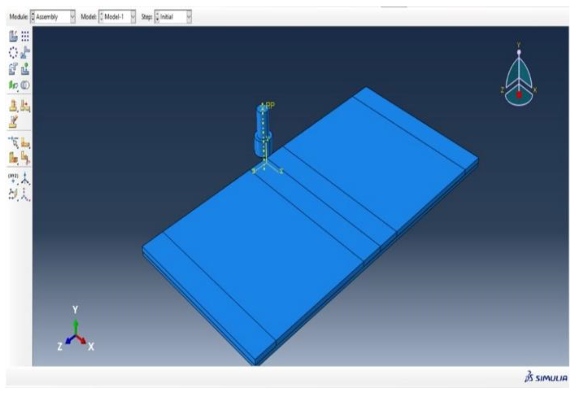
Figure 18.
interaction of system.
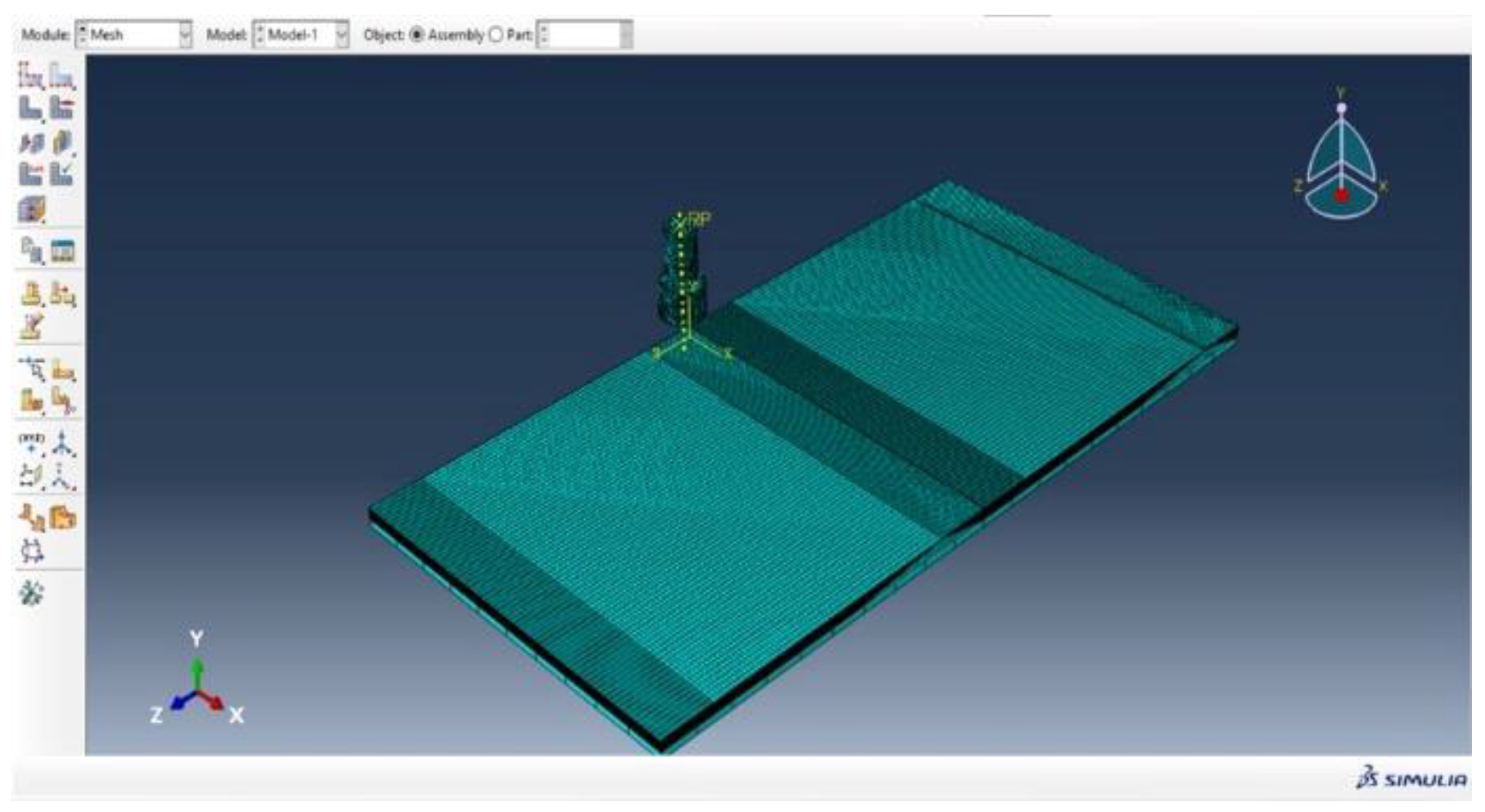
Load and Meshing:
Loads, boundary conditions, and tool movements are set to simulate the welding process, while a detailed mesh is created to ensure accurate simulation outcomes.
Figure 19.
Load of the system.
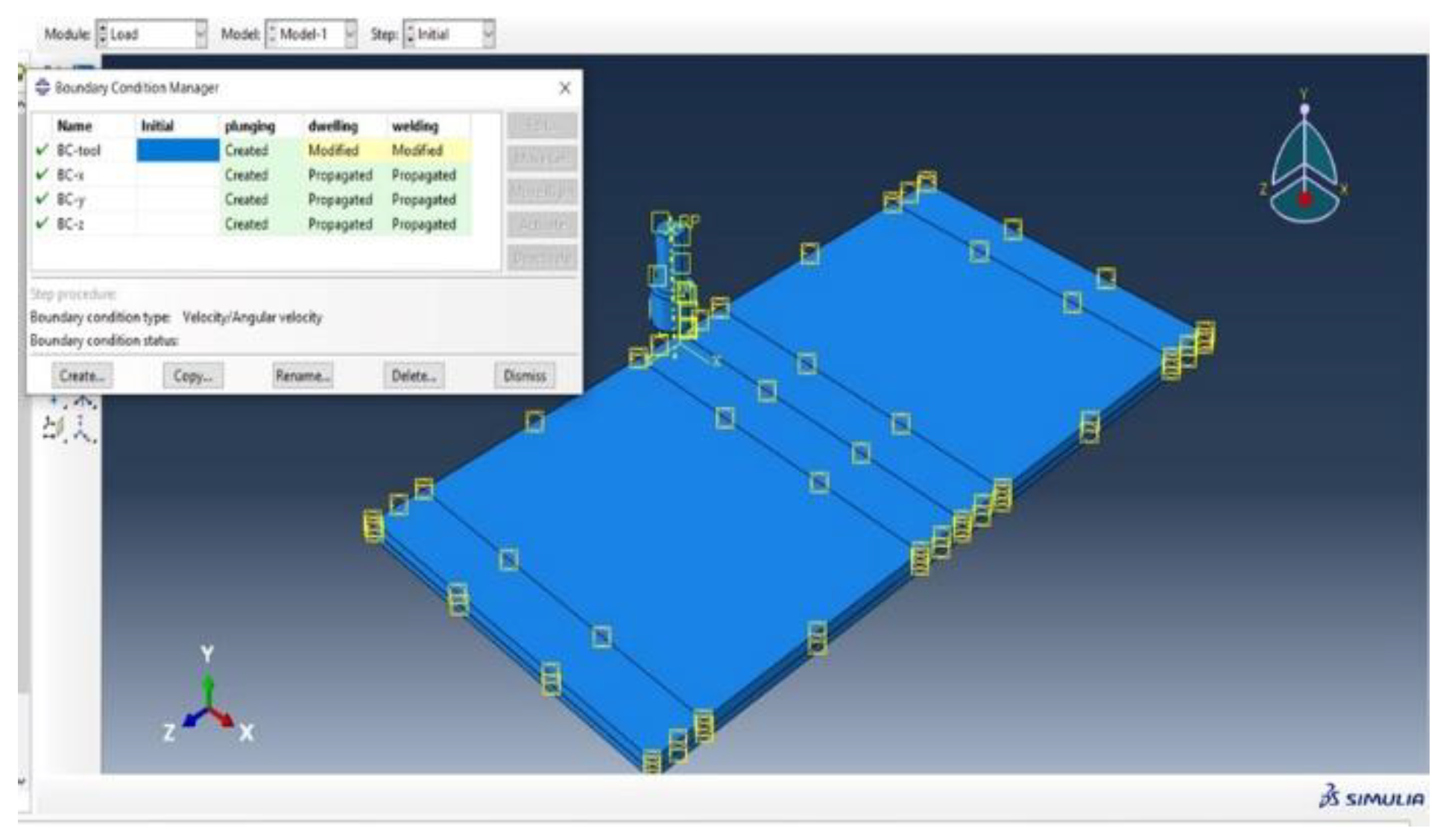
Figure 20.
Mesh of the system.
Thermal Profile and Stress Distribution:
The simulation shows temperature gradients and von Mises stress distribution, with the highest values near the tool, highlighting areas of heat generation and mechanical deformation.
Figure 21.
Thermal profile 1.
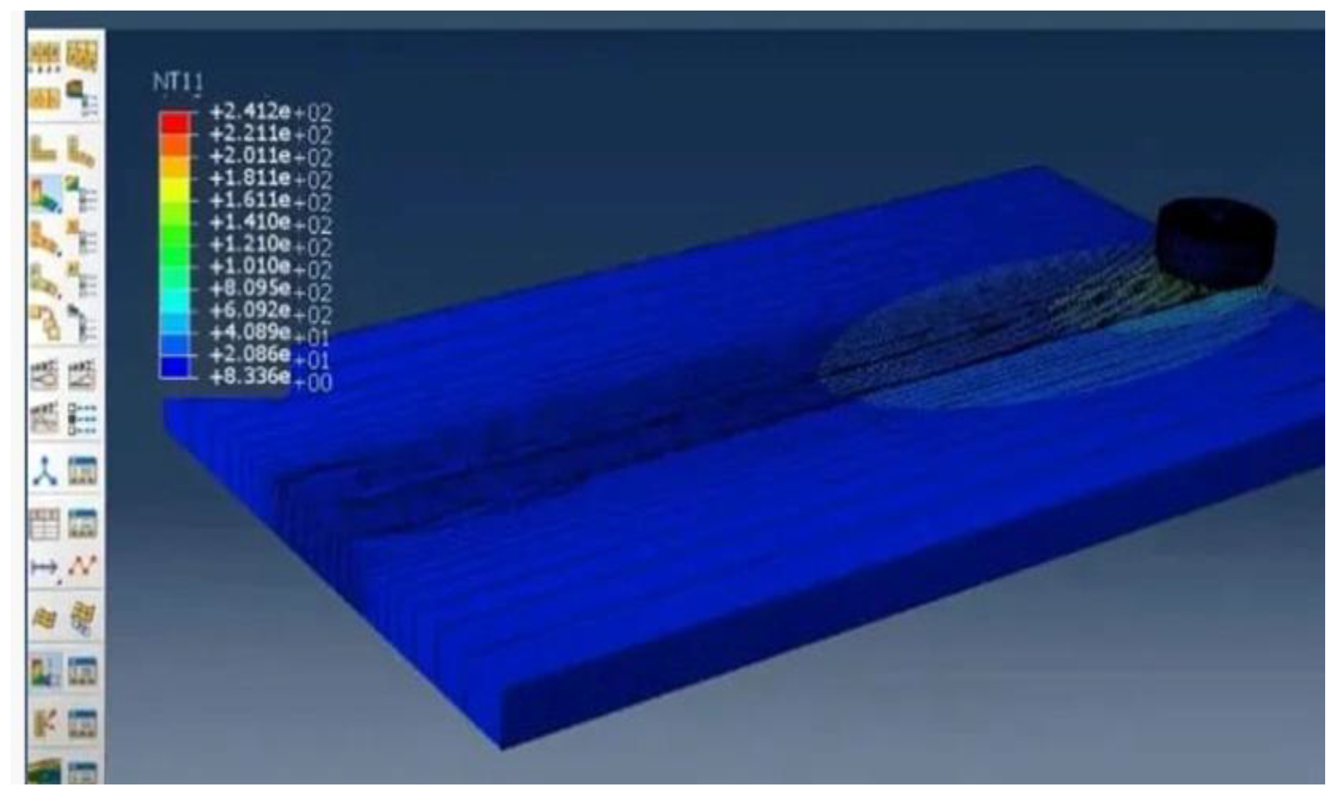
Figure 22.
Thermal profile 2.
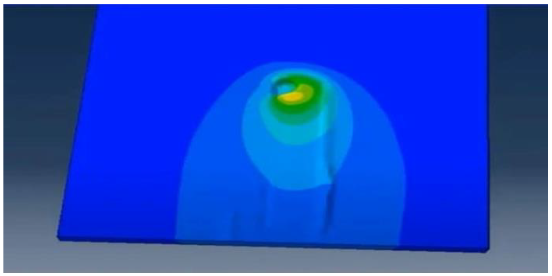
Figure 23.
Stresses.
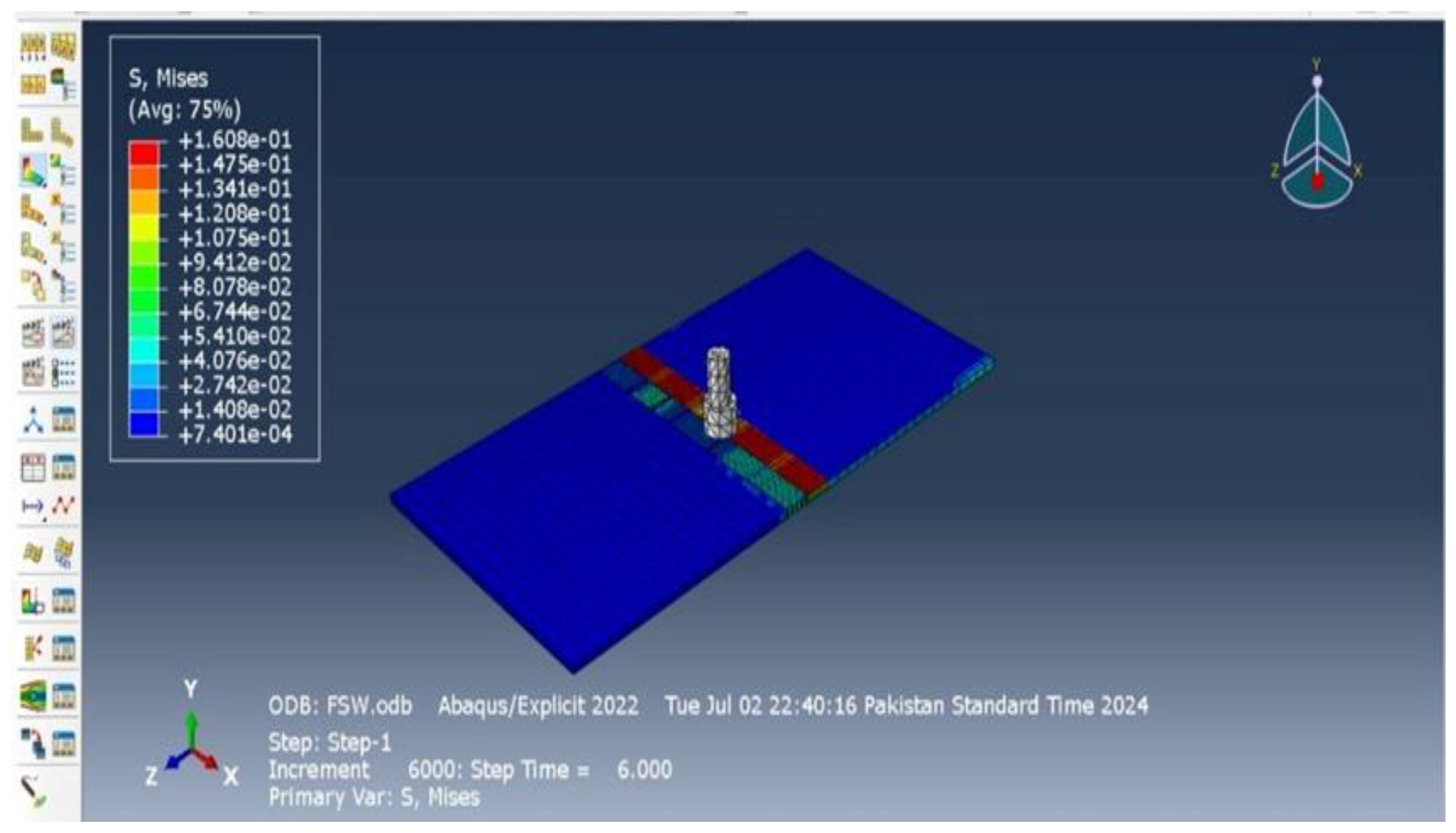
The simulation analyzed temperature and stress distributions during FSW of aluminum 6061 and composites using Abaqus. High temperatures and von Mises stress near the tool indicated effective heat generation and mechanical deformation, leading to optimized parameters for strong, durable welds and ensuring quality and performance standards were met.
5. Results and Discussion
5.1. Hardening Test
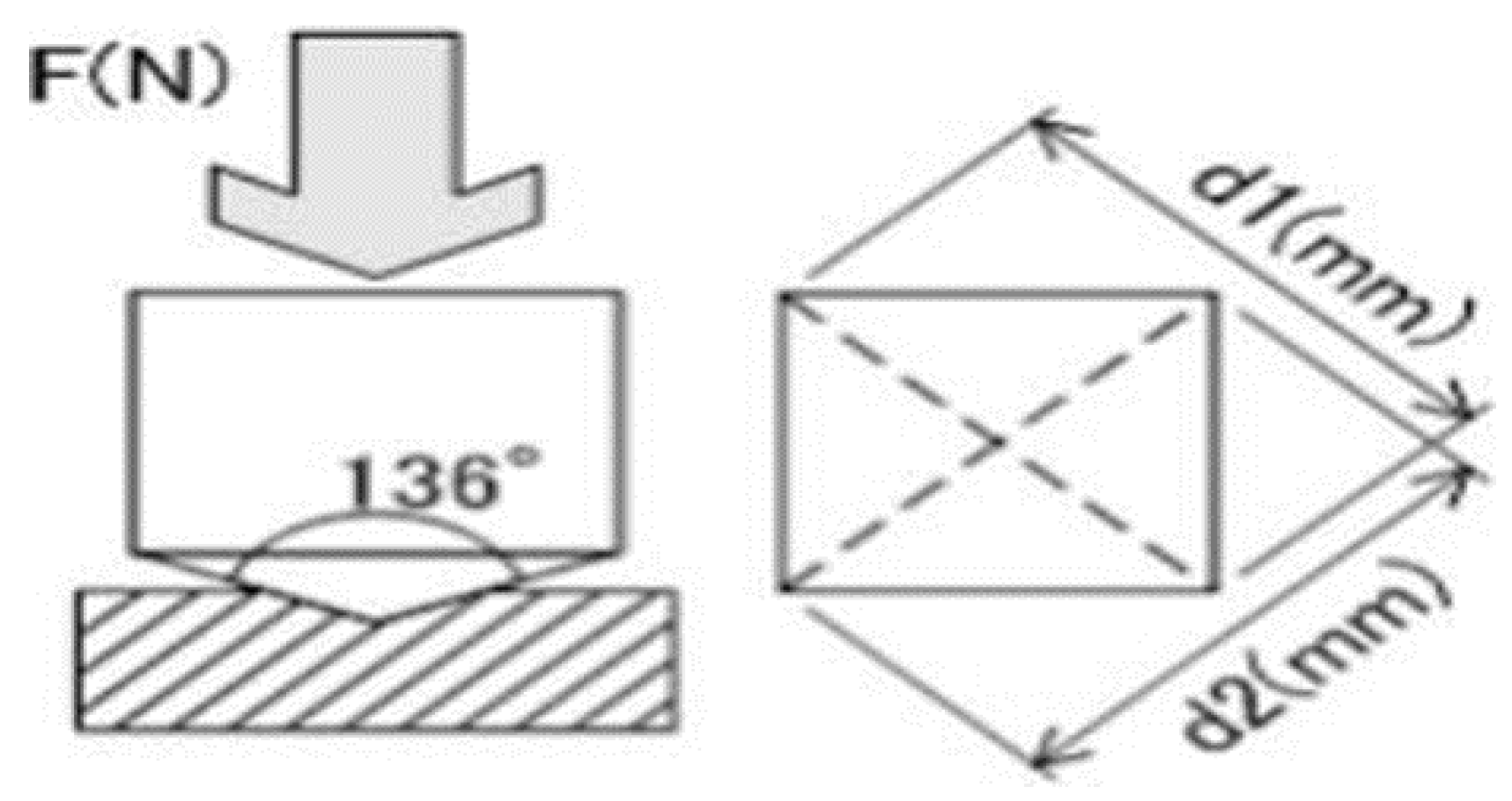
To determine the hardness of the welded joint, heat-affected zone, and base metal, a Vickers hardness test was conducted using a diamond indenter. A force of 10 kg was applied to create indentations in different zones of the plate. The depth of these indentations was measured using a scope view and calculated to determine the hardness.
The hardness value, or Vickers Hardness Number (HV), was calculated using the formula:
HV= 1.854(F/D2)
Where HV is vicker hardness number, F is the force to be applied that is 100N and D2 would be the average of two diameters as shown in a Figure 24
Figure 24.
Indentation model of hardness machine.
- I.
- Hardness test result of Aluminium and composite weld:
The Vickers Hardness Number indicates the material's resistance to indentation. The hardness values for the polymer-based composite plate and aluminum weld through FSW are measured using this method.
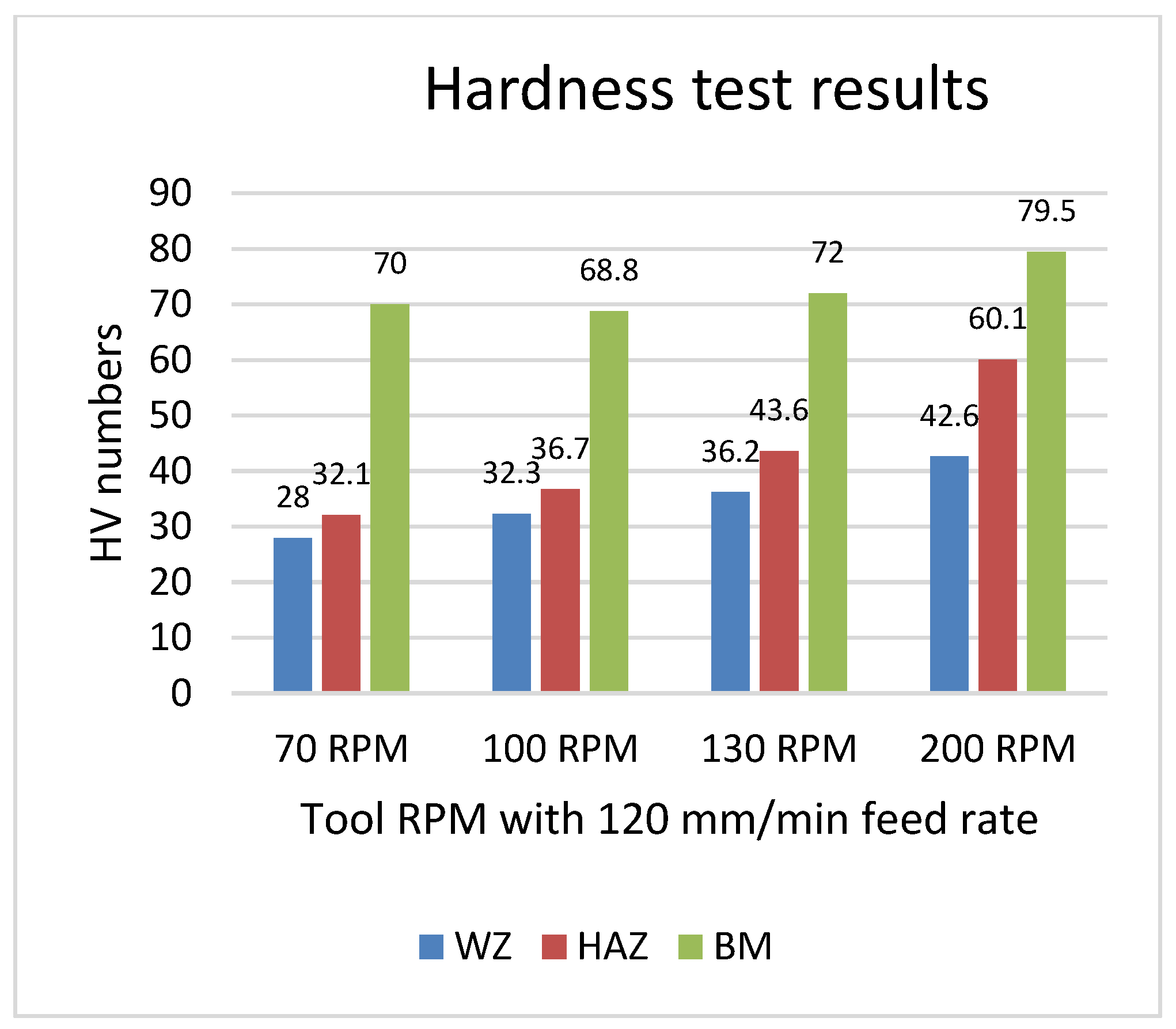
Table 5.
Hardness test result of Al 6061 with composite welded plates.
| Sample | WZ | HAZ | BM |
|---|---|---|---|
| S1 | 28 | 32.1 | 70 |
| S2 | 32.3 | 36.7 | 68.8 |
| S3 | 36.2 | 43.6 | 72 |
| S4 | 42.6 | 60.1 | 79.5 |
| S5 | 34.1 | 45.3 | 65.4 |
| S6 | 27.8 | 36.1 | 61 |
| S7 | 24.4 | 48.3 | 60.5 |
| S8 | 12 | 22.3 | 66.3 |
Sample 4 exhibited the highest hardness number at the Weld Zone (WZ), Heat-Affected Zone (HAZ), and Base Metal (BM) due to its optimal weld condition. However, the hardness of the base material (BM) was observed to be lower near the HAZ. This reduction is attributed to the indentation's proximity to the HAZ, where thermal effects from welding have altered the material properties, leading to a lower hardness reading compared to the original, unaffected base metal.
Figure 25.
Graph represent trends for hardness test at 120mm/min feed rate.
Now the RPM was same and feed rate is change, the results obtained are,
Figure 26.
Graph represent trends for hardness test at 180mm/min feed rate.
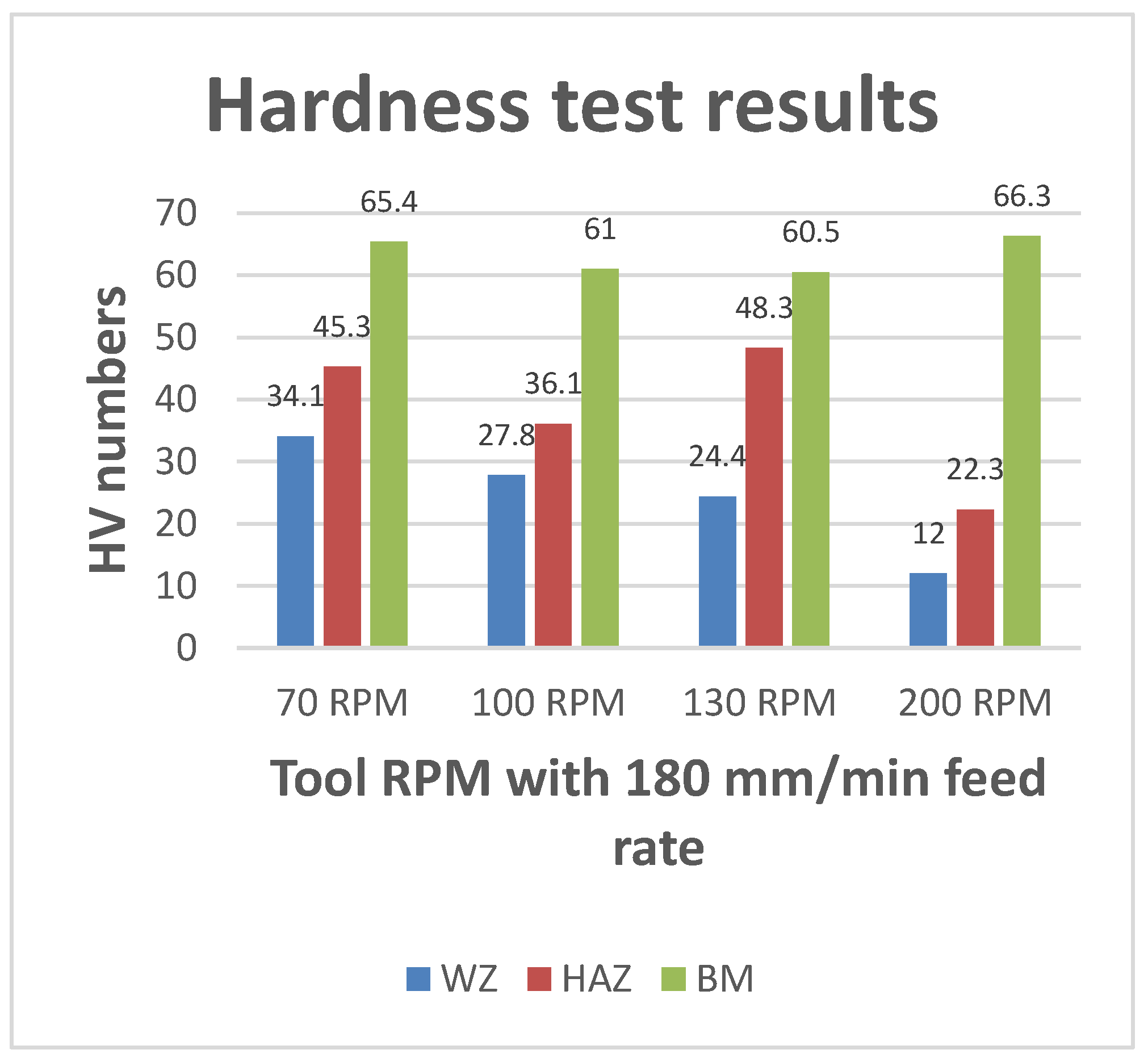
Analysis of both graphs indicates that reducing tool RPM during FSW of the composite plate with aluminum improves weld quality, while increasing the feed rate diminishes it. In Graph 1, Sample 4 shows the highest hardness number, whereas in Graph 2, Sample 1 exhibits the highest hardness number.
- II.
- Hardness test result of Al 6061 and Al 2029 weld:
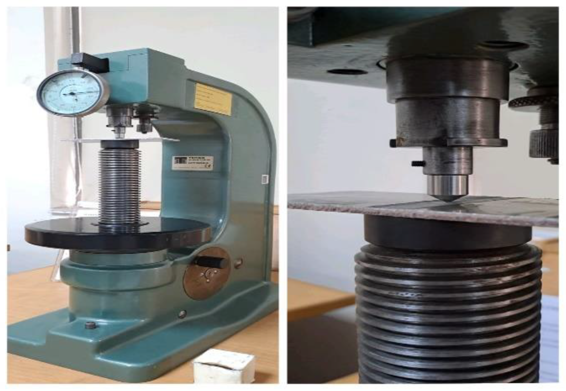
The same hardness testing procedure was applied to Al 6061 and Al 2029 using the older hardness machine available in the mechanics lab.
Figure 27.
Hardness test Machine at the Mechanics Lab.
The hardness result obtained from the machine for Al 6061 and Al 2029 is give below
Table 6.
Hardness test result of Al 2029 and Al 60161 welded plates.
| Sample | WZ | HAZ | BM |
|---|---|---|---|
| S1 | 82 | 86.2 | 101.3 |
| S2 | 88.4 | 92 | 101 |
| S3 | 91.2 | 96.2 | 99.6 |
| S4 | 99.6 | 103.1 | 112.1 |
| S5 | 89.9 | 97.3 | 106.4 |
| S6 | 85.2 | 98.1 | 110.3 |
Figure 28.
Hardness test result for Al 6061 and Al 2029 weld.
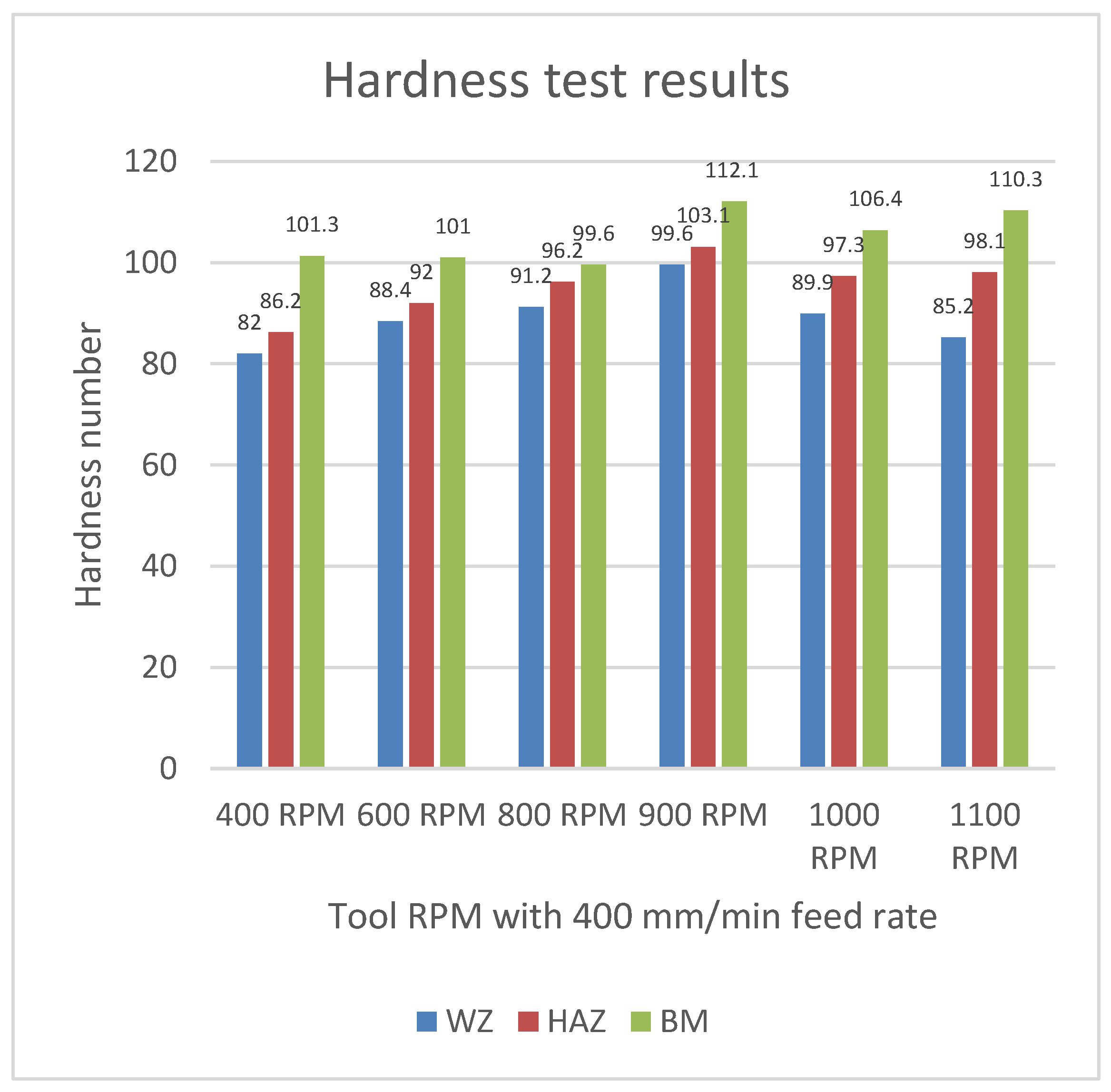
The graph shows that Sample 4, with 900 RPM and a 400 mm/min feed rate, has the highest hardness number at the WZ, HAZ, and BM. Comparing the two FSW results—one on the composite with Al 6061 and the other on Al 6061 and Al 2029—it is evident that the weld quality of dissimilar aluminum alloys is significantly better than that of the Al 6061 and composite plate, as detailed in the results section.
5.2. Tensile Test
A Universal Testing Machine (UTM) was used to perform tensile tests on the specimen, applying controlled tension until fracture. The test results included Ultimate Tensile Strength, elongation, yield strength, true stress, strain, and area reduction, ensuring optimal weld quality.
Figure 29.
Tensile specimen adjusted at Tensile Testing Machine.
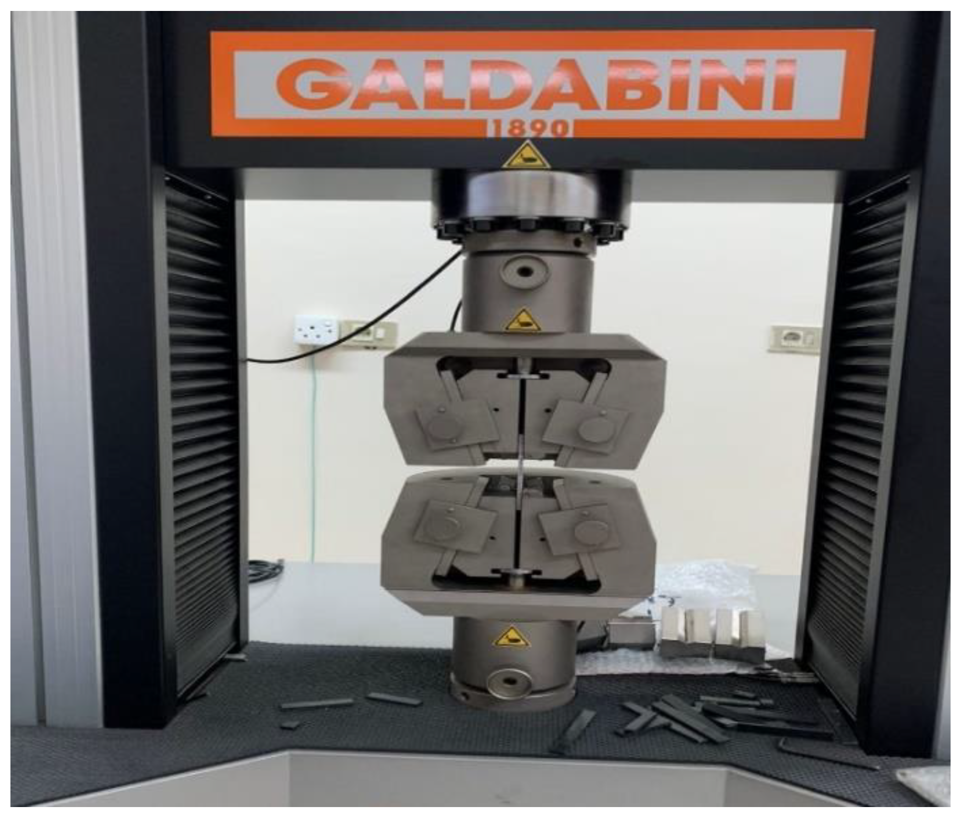
Specimen which were cut according to ASTM standards, will be fitted between the jaws of the machine and strain rate of 5mm/min is applied to perform the test.
- I.
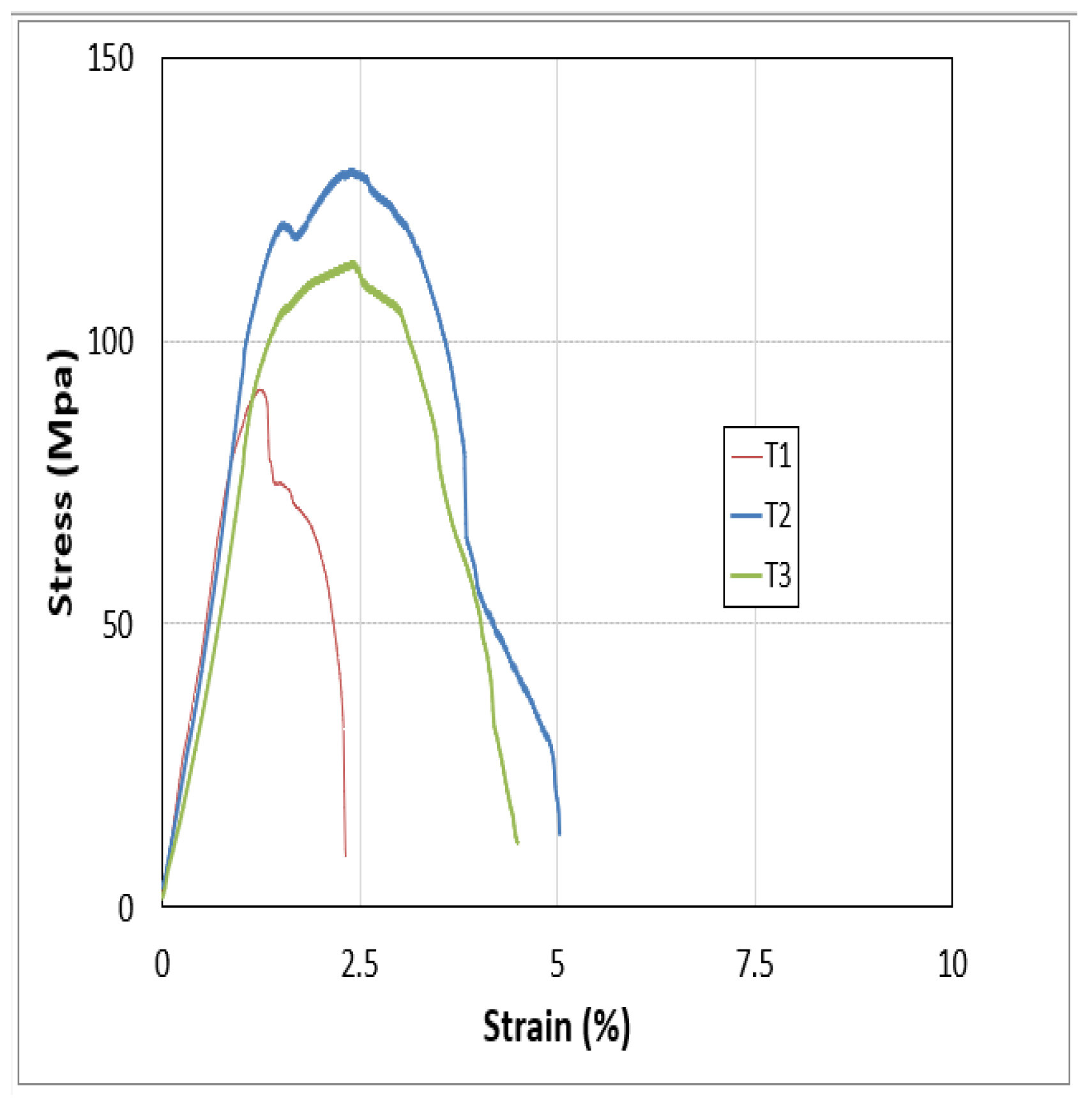
- Tensile Testing on Aluminium and composite plate weld:
Photographs from the FSW process show that the weld quality of the aluminum and composite plate is inferior to that of different aluminum grades. During tensile testing, as the load increases, elongation occurs, leading to plastic deformation after the yield point, and fracture after reaching the Ultimate Tensile Strength (UTS). The UTS and fracture strength are summarized in the table and plotted on the graphs.
Figure 30.
Stress strain curve of sample 4.

Sample 4 demonstrated superior weld integrity, enduring 14 MPa with 8% elongation before fracturing, whereas Sample 1 sustained just 4 MPa with 3% elongation.
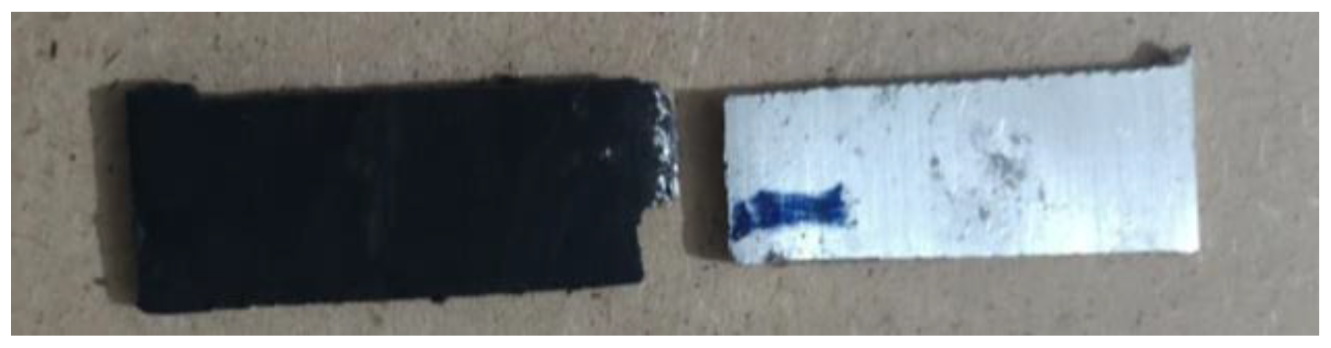
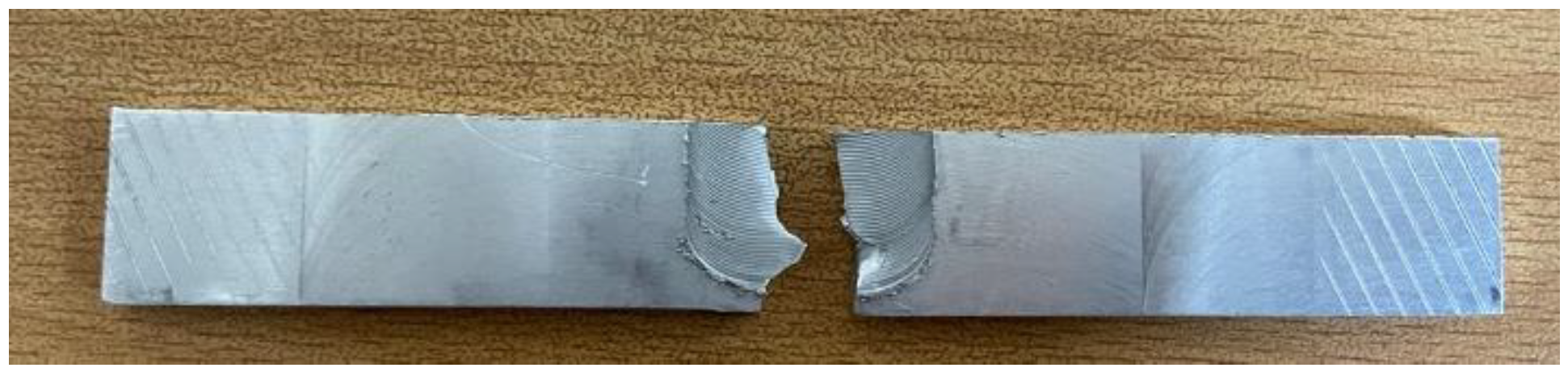
Figure 31.
Fractured sample of Al-composite.
- II.
- Tensile Test on Al 6061 and Al 2029:
The tensile test results for different grades of aluminum are summarized in the table below, showing the UTS and fracture strength of each sample. It was observed that increasing the RPM while keeping the feed rate constant led to a decrease in UTS and fracture strength. This reduction is attributed to the higher temperatures in the welded zone at increased RPMs, which accelerates the onset of metal failure.
| Samples | UTS (MPa) | Fracture strength (MPa) | Elongation % |
| S1 | 111.4 | 115.41 | 5.1 |
| S2 | 148.6 | 155.82 | 5.34 |
| S3 | 170 | 177.78 | 6.28 |
| S4 | 214 | 240.6 | 13.25 |
| S5 | 157.6 | 178.72 | 14.28 |
| S6 | 131.6 | 141.2 | 15.14 |
Figure 32.
Stress strain curve of sample # 1.
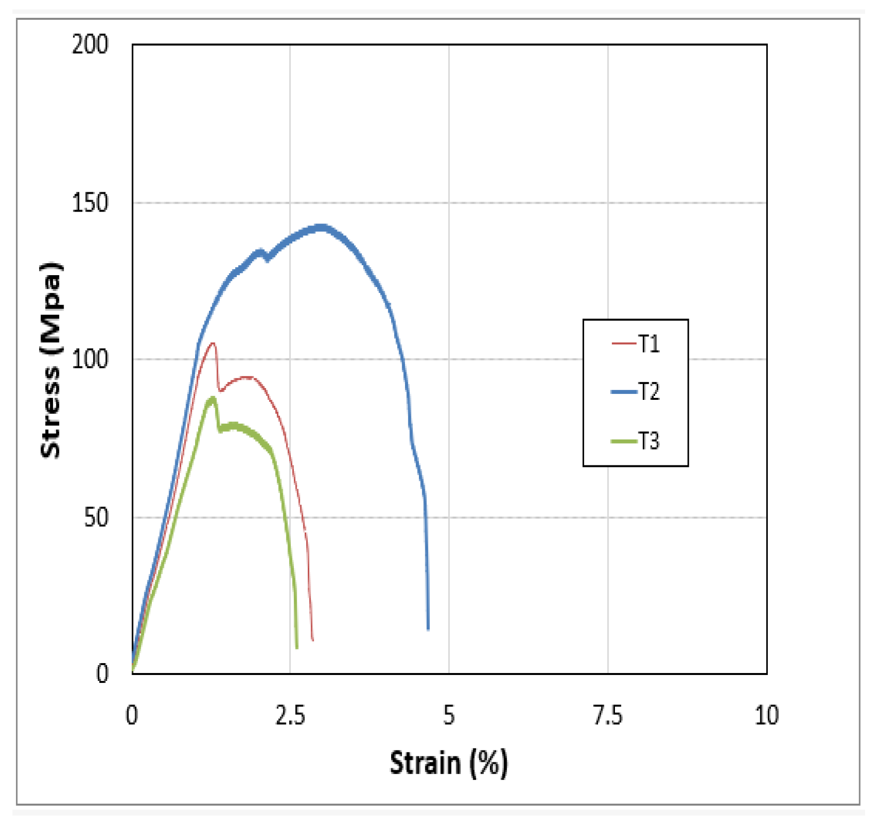
Figure 33.
Stress strain curve of sample # 2.
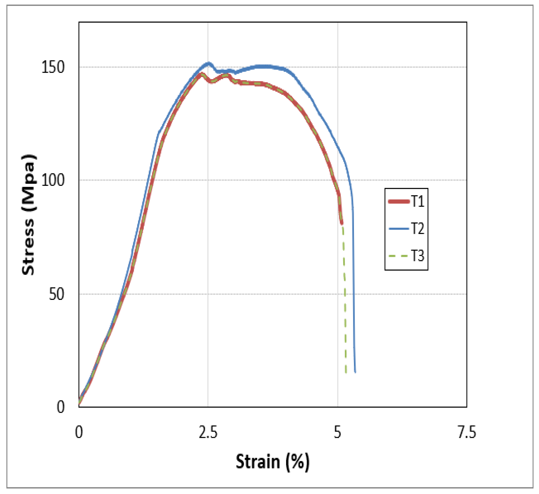
Figure 34.
Stress strain curve of sample # 3.
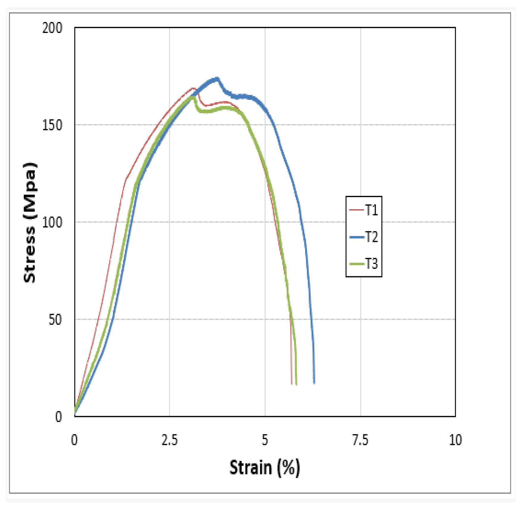
Figure 35.
Stress strain curve of sample # 4.
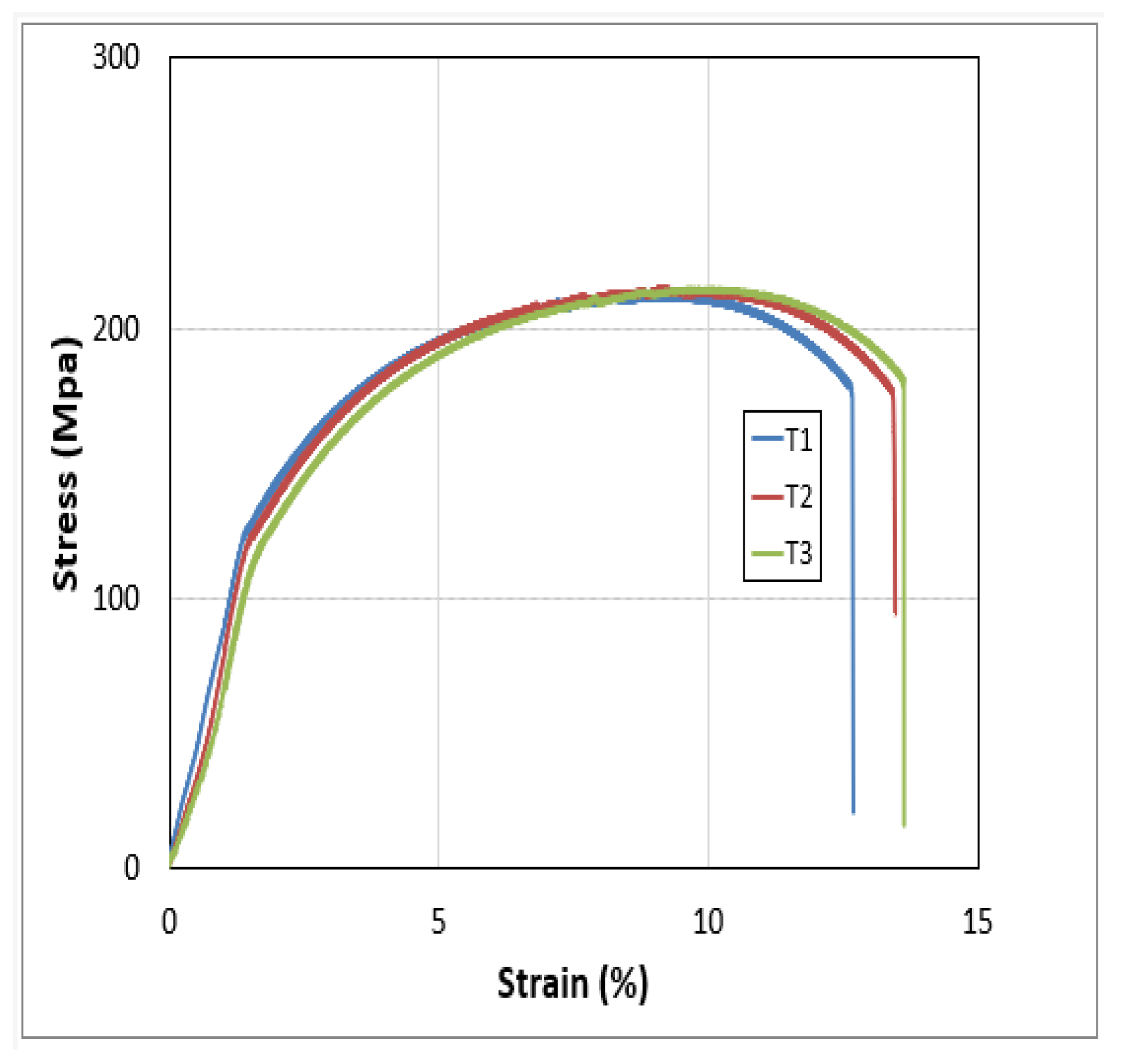
Figure 36.
Stress strain curve of sample # 5.
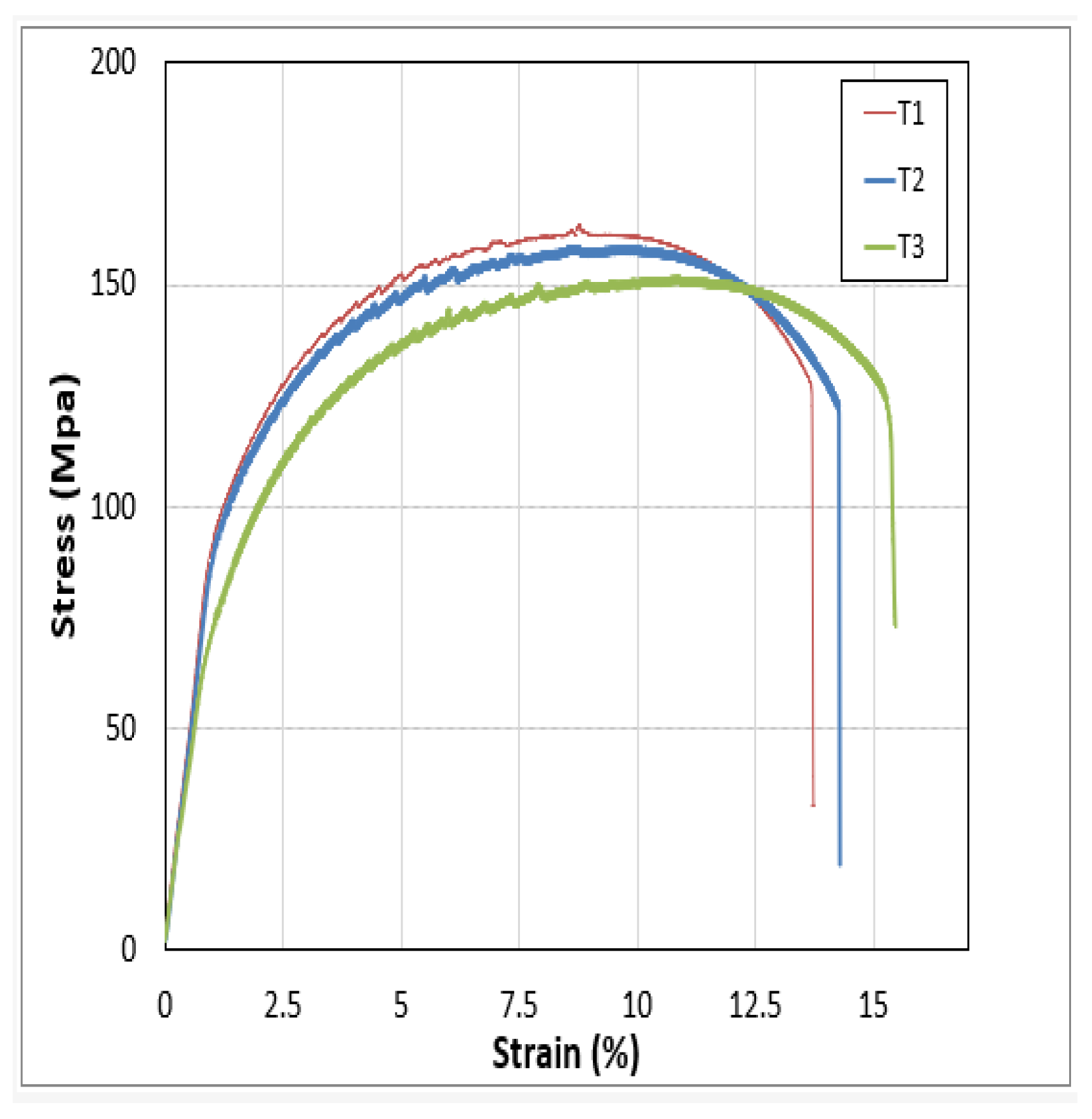
Figure 37.
Stress strain curve of sample # 6.
From the above graph it can be analyzed that the UTS and fracture strength of the sample 4 is the highest but after the sample 4 the UTS decreased due to increasing the RPM of the Tool which provides the maximum temperature that pushed the metal plates towards the failure.
Figure 38.
Fractured sample of Al 6061- Al 2029.
5.3. Comparison of FSW of Al 6061-Composite Plates with AL 6061-Al 2029
Both welds, performed via Friction Stir Welding with different parameters, showed that Al 6061-Al 2029 had significantly better weld quality than Al 6061-Composite plates. Vickers hardness and tensile tests were conducted to assess the weld quality, with the results summarized below.
Figure 39.
Comparison of Hardness test of two FSW process.
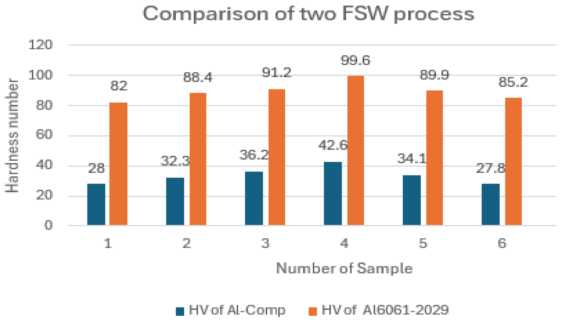
The maximum hardness number for FSW of aluminum to composite plate is 42, while for Al 6061 to Al 2029, it reaches 99. This indicates that the weld quality of Al 6061 to Al 2029 is significantly superior, attributed to better material mixing. The weak weld strength of the Al-composite joint results in a lower hardness number. As hardness increases, so does the material's resistance to external forces. Following the hardness test, tensile tests were conducted, and the results comparing both processes are presented in the graph below.
Figure 40.
Comparison of Tensile testing of two FSW process.

The weld strength of the composite-aluminum joint in Friction Stir Welding (FSW) is considerably weaker than that of Al 6061-2029, primarily due to the significant differences in material properties. The disparity in thermal conductivity and expansion coefficients between the composite and aluminum leads to uneven heating and cooling during the welding process. This thermal mismatch creates residual stresses and defects at the weld interface, adversely affecting mechanical properties. Additionally, the microstructural differences between the materials result in a less homogeneous weld zone, further weakening the joint. During FSW, the composite tends to deform and melt more quickly than aluminum, leading to improper mixing and reduced weld quality. These factors collectively result in lower tensile strength and hardness values for the composite-aluminum weld, underscoring the inherent challenges of welding dissimilar materials compared to similar aluminum alloys.
6. Conclusions
This paper on Friction Stir Welding (FSW) of two dissimilar materials has yielded significant findings and conclusions drawn from an extensive review of literature, experimentation, and case studies. FSW offers numerous advantages over traditional welding processes and has been successfully applied to both similar and dissimilar metals. However, this research focuses on FSW of polymer-based composite plates with aluminum, which presents unique challenges and opportunities in the context of modern technology. The quality of the FSW weld is primarily dependent on the tool design and process parameters. Selecting the optimal parameters is crucial for achieving a well-defined joint.
The challenges of FSW between aluminum and composite materials arise from the tool design, as conventional tools generate excessive heat, causing the composite plate to melt before the aluminum undergoes plastic deformation. This leads to poor weld quality. In contrast, FSW between Al 6061 and Al 2029 demonstrated excellent weld quality using conventional tools and process parameters. Optimal results were achieved at a feed rate of 400 mm/min and 900 RPM for aluminum alloys, and at 200 RPM with a 120 mm/min feed rate for aluminum-composite welding.
Ultimately, a tool was designed to optimize the FSW process for welding metal with composite materials. Continued research and development in FSW are essential, as exploring new materials, fine-tuning process parameters, and expanding the range of applications will help unlock the full potential of this innovative welding technique.
Future Work
The FSW of composite to aluminium.yields lower tensile strength and hardness values, reflecting the inherent challenges and limitations of welding dissimilar materials compared to welding similar aluminum alloys. The solution to this problem lies in the choice of the FSW tool. Currently, a conventional FSW tool is being used, which is not optimal for welding.dissimilar materials like aluminum and composites. According to literature, the double shoulder tool has been identified as the ideal choice for such welds. This tool design can enhance the welding process by ensuring better mixing and bonding between the aluminum and composite materials, ultimately improving the weld strength.
The tool which we designed for this kind of weld is the top priority of research due to advancement in the welding techniques.
Figure 41.
CAD Model of the double shoulder FSW Tool.
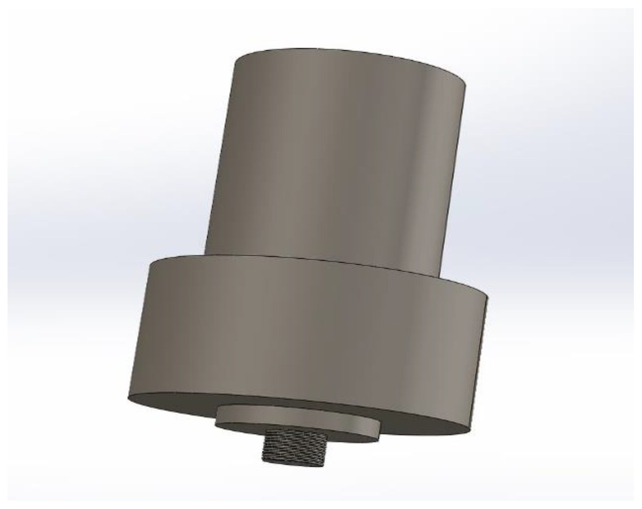
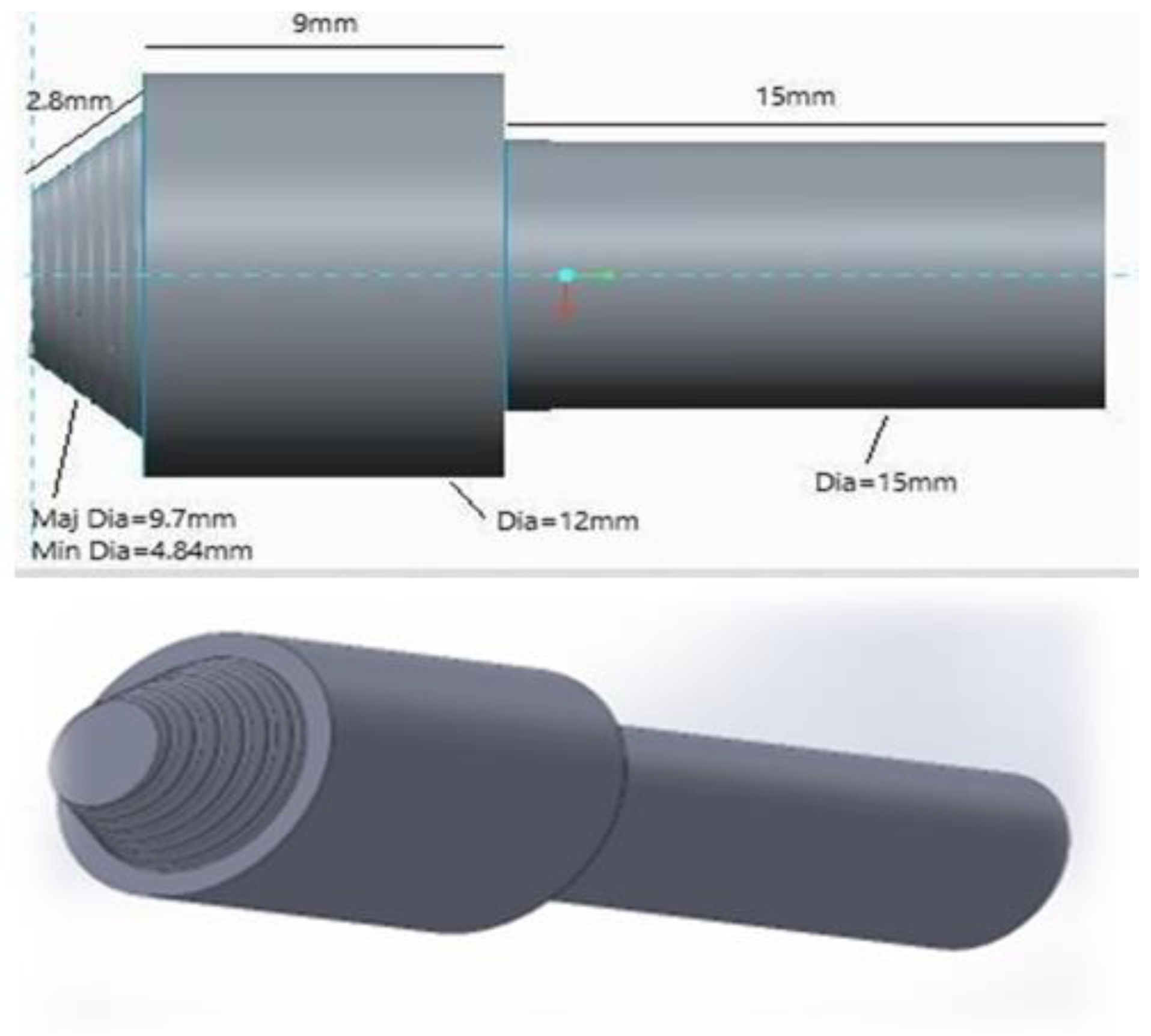
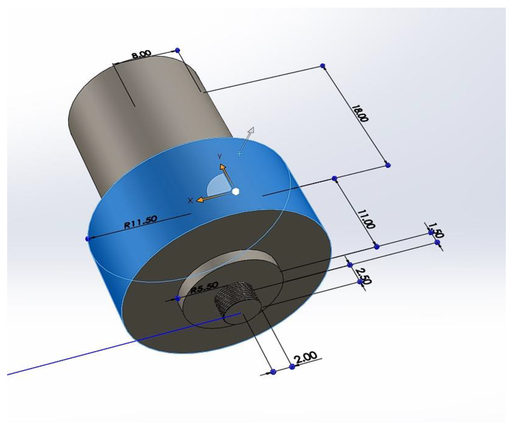
Figure 42.
Dimensions of the FSW tool for 3mm plate.
This FSW Tool is called Double shoulder tool. The first shoulder which is comparative small as compared to other help the material to plastically deform and then by plunging the required depth force from both shoulders can mix the material properly.
References
- S. Kumar, G. Bhushan, and P. Chandna, “A CRITICAL REVIEW ON OPTIMIZATION OF PROCESS PARAMETERS OF FRICTION STIR WELDING,” 2017.
- G. Gebreamlak, B. Singh, and G. Gebreamlak Yeshitla, “Friction Stir Welding and its Applications: A Review The necessity of Technology Innovation and Transfer in TVET for Micro Small Enterprises in Ethiopia View project Friction Stir Welding and its Applications: A Review,” High Technol. Lett., vol. 26, no. 11, p. 2020, [Online]. Available online: https://www.researchgate.net/publication/345133110.
- P. M. Mashinini, “Process window for Friction Stir Welding of 3 mm Titanium (Ti-6Al-4V),” no. May, p. 143, 2010.
- D. Burford, C. Widener, and B. Tweedy, “Advances in friction stir welding for aerospace applications,” Collect. Tech. Pap. - 6th AIAA Aviat. Technol. Integr. Oper. Conf., vol. 1, no. September, pp. 257–270, 2006. [CrossRef]
- P. F. Mendez and T. W. Eagar, “Penetration and defect formation in high-current arc welding,” Weld. J. (Miami, Fla), vol. 82, no. 10, 2003.
- D. G. Sanders, M. Ramulu, E. J. Klock-McCook, P. D. Edwards, A. P. Reynolds, and T. Trapp, “Characterization of superplastically formed friction stir weld in titanium 6AL-4V: Preliminary results,” J. Mater. Eng. Perform., vol. 17, no. 2, pp. 187–192, 2008. [CrossRef]
- X. H. Zeng, P. Xue, D. Wang, D. R. Ni, B. L. Xiao, and Z. Y. Ma, “Effect of Processing Parameters on Plastic Flow and Defect Formation in Friction-Stir-Welded Aluminum Alloy,” Metall. Mater. Trans. A Phys. Metall. Mater. Sci., vol. 49, no. 7, pp. 2673–2683, 2018. [CrossRef]
- S. W. Kallee, Industrial applications of friction stir welding. Woodhead Publishing Limited, 2009. [CrossRef]
- L. E. Murr and C. Pizaña, “Dynamic recrystallization: The dynamic deformation regime,” Metall. Mater. Trans. A Phys. Metall. Mater. Sci., vol. 38 A, no. 11, pp. 2611–2628, 2007. [CrossRef]
- T. Sakai, A. Belyakov, R. Kaibyshev, H. Miura, and J. J. Jonas, “Dynamic and post-dynamic recrystallization under hot, cold and severe plastic deformation conditions,” Prog. Mater. Sci., vol. 60, no. 1, pp. 130–207, 2014. [CrossRef]
- L. Commin, M. Dumont, J. E. Masse, and L. Barrallier, “Friction stir welding of AZ31 magnesium alloy rolled sheets: Influence of processing parameters,” Acta Mater., vol. 57, no. 2, pp. 326–334, 2009. [CrossRef]
- X. Meng, Y. Huang, J. Cao, J. Shen, and J. F. dos Santos, “Recent progress on control strategies for inherent issues in friction stir welding,” Prog. Mater. Sci., vol. 115, p. 100706, 2021. [CrossRef]
- T. Watanabe, H. Takayama, and A. Yanagisawa, “Joining of aluminum alloy to steel by friction stir welding,” J. Mater. Process. Technol., vol. 178, no. 1–3, pp. 342–349, 2006. [CrossRef]
- F. Simoes and D. M. Rodrigues, “Material flow and thermo-mechanical conditions during Friction Stir Welding of polymers: Literature review, experimental results and empirical analysis,” Mater. Des., vol. 59, pp. 344–351, 2014. [CrossRef]
- F. Lambiase and S. Genna, “Homogenization of temperature distribution at metal-polymer interface during Laser Direct Joining,” Opt. Laser Technol., vol. 128, no. December 2019, p. 106226, 2020. [CrossRef]
- M. Grujicic et al., “An overview of the polymer-to-metal direct-adhesion hybrid technologies for load-bearing automotive components,” J. Mater. Process. Technol., vol. 197, no. 1–3, pp. 363–373, 2008. [CrossRef]
- S. G. Kim, A. Suzuki, N. Takata, and M. Kobashi, “Joining of metals and polymers using powder metallurgy with laser irradiation,” J. Mater. Process. Technol., vol. 270, pp. 1–7, 2019. [CrossRef]
- N. Konchakova, F. Balle, F. J. Barth, R. Mueller, D. Eifler, and P. Steinmann, “Finite element analysis of an inelastic interface in ultrasonic welded metal/fibre-reinforced polymer joints,” Comput. Mater. Sci., vol. 50, no. 1, pp. 184–190, 2010. [CrossRef]
- S. Zhao et al., “Effects of tool geometry on friction stir welding of AA6061 to TRIP steel,” J. Mater. Process. Technol., vol. 261, pp. 39–49, 2018. [CrossRef]
- G. Casalino, P. Leo, M. Mortello, P. Perulli, and A. Varone, “Effects of laser offset and hybrid welding on microstructure and IMC in Fe-Al dissimilar welding,” Metals (Basel)., vol. 7, no. 8, 2017. [CrossRef]
- R. Ghiya and V. J. Badheka, “A review of friction stir lap welding of polymer to metal,” Polymer-Plastics Technology and Materials, vol. 60, no. 18. Taylor and Francis Ltd., pp. 1966–1995, 2021. [CrossRef]
- S. G. Advani and K.-T. Hsiao, “Introduction to composites and manufacturing processes,” in Manufacturing Techniques for Polymer Matrix Composites (PMCs), Elsevier, 2012, pp. 1–12. [CrossRef]
- P. Patel, S. Patel, and H. Shah, “Design and Experimental study of Friction stir welding of AA6061-T6 Alloy for optimization of welding parameters by using Lathe Machine,” pp. 26–32, 201.
Disclaimer/Publisher’s Note: The statements, opinions and data contained in all publications are solely those of the individual author(s) and contributor(s) and not of MDPI and/or the editor(s). MDPI and/or the editor(s) disclaim responsibility for any injury to people or property resulting from any ideas, methods, instructions or products referred to in the content. |
© 2024 by the authors. Licensee MDPI, Basel, Switzerland. This article is an open access article distributed under the terms and conditions of the Creative Commons Attribution (CC BY) license (http://creativecommons.org/licenses/by/4.0/).
Copyright: This open access article is published under a Creative Commons CC BY 4.0 license, which permit the free download, distribution, and reuse, provided that the author and preprint are cited in any reuse.


