Submitted:
08 March 2025
Posted:
10 March 2025
You are already at the latest version
Abstract
A novel deployable reflector antenna for small satellites has been designed, fabricated, and experimentally validated. The reflector utilizes a doubly curved flexible surface manufactured from a triaxially woven fabric-reinforced silicone (TWFS) composite. By leveraging high-strain composite materials, the design enables a highly compact stowed configuration while maintaining precise surface accuracy upon deployment. The deployment mechanism is proposed to accommodate a 0.6 m diameter parabolic reflector within a minimal stowed volume, optimizing space efficiency for satellite integration. To validate this concept, a prototype of the reflector antenna has been fabricated and demonstrated the feasibility and effectiveness of the proposed approach.
Keywords:
Reflector Antenna
; Flexible Surface
; Deployment Mechanism
; Triaxially Woven Fabric-reinforced Silicone (TWFS)
; Small Satellites
1. Introduction
The development of large space structures has been a growing area of research aimed at enhancing spacecraft performance for a wide range of missions. As space structures continue to increase in size, manufacturing and launch costs rise significantly, driving the need for innovative lightweight deployable structures [1]. Research on small satellites equipped with deployable reflector antennas for Earth observation such as weather monitoring, ocean surveillance, and environmental analysis has gained substantial attention.
Deployable antennas for small satellites, particularly CubeSats, are of significant interest due to their ability to achieve high-gain communication while maintaining a compact form factor during launch. The rapid advancements in CubeSat technology have intensified the demand for high-performance deployable reflector antennas to support telecommunication, remote sensing, and scientific missions. Conventional CubeSat antennas are often constrained by their limited size, restricting their ability to achieve high gain and narrow beamwidths. To overcome this limitation, deployable reflector antennas have been designed to maximize the effective aperture while remaining compact in a stowed configuration [2]. Deployable reflector antennas must maintain precise surface accuracy, particularly for high-frequency applications such as Ka-band communications, where surface errors must remain within λ/50 to λ/100 to ensure optimal performance [3]. Several engineering approaches have been explored to achieve high-precision deployable reflectors, including metallic mesh reflectors supported by rigid ribs, as demonstrated in the RainCube mission [4]. Although these systems have been successfully deployed, they are often limited in scalability due to their reliance on numerous mechanical support structures, which increase complexity and stowage volume.
To address these challenges, advanced materials such as carbon-fiber reinforced silicone (CFRS) and other high-strain composites have been investigated for deployable reflector applications [5]. Recent advancements in shell-membrane materials, such as a triaxially woven fabric (TWF) composite, have enabled the development of deployable reflectors that retain their shape upon deployment [6,7,8]. Large-scale TWF composites are characterized by in-plane quasi-isotropic thermos-mechanical behaviors [9]. The inherent isotropy of TWF enables the potential use of a single layer as a composite reinforcement. Additionally, the extremely low aerial density of single-layer TWF composites, attributed to their lattice structure, facilitates the development of ultra-lightweight designs [10,11].
In this study, an innovative deployable reflector antenna for small satellites is designed, fabricated, and experimentally validated. A doubly curved flexible surface reflector is manufactured using a triaxially woven fabric-reinforced silicone (TWFS) composite. The mechanical and electrical properties of the TWFS are characterized experimentally, forming the basis for the reflector’s structural and electromagnetic design. The antenna’s electrical performance is analyzed. A deployment mechanism is introduced, leveraging high-strain TWFS composite materials to achieve a compact stowed volume while ensuring high surface accuracy upon deployment. To demonstrate the feasibility of this approach, a 0.6 m reflector prototype is designed, fabricated, and tested.
2. Mechanical and Electrical Properties of TWFS Composites
2.1. Fabrication of the TWFS Composite
A flexible surface reflector is composed of two materials: carbon fibers and a silicone elastomer. A triaxially woven carbon T300 fiber fabric of SK-802, is used to reinforce a space-qualified silicone elastomer. The elastomer can be cured at room temperature and gives an advantage of manufacturing large seized doubly curved structures on significantly cheap molds. A basic geometry of the TWFS specimen is shown in Figure 1. This TWF has dry fabric thickness of 0.13 mm and dry fiber tow width of 0.9 mm. The manufacturing process for a single layer of TWFS is following basic steps: 1) cutting of a reinforcing material, 2) hand laminating with relatively high viscosity matrix material makes it particularly important to care for the triaxially woven fabrics, 3) applying of a matrix material and impregnation of the reinforcing material, 4) Curing of the composite at room temperature.
High flexibility of the TWFS calls for the development of the special methods and tools for testing as well as for the analysis of mechanical properties for its characterization. The uniaxial tensile test is performed following the standard test method for the tensile properties of plastics [12]. Use of standard strain measurement techniques is complicated and sometimes not possible to the very low stiffness of the silicone: it is much lower than of the strain gauges and attachment of extensometers to the TWFS surface is not reliable. So, a 3D strain measurement system, ARAMIS [13], is used for measuring the strain. Figure 2 shows the experimental setup for tensile tests.
In the numerical models of TWF composites, the crossing tows have to be modeled separately from each other due the line (beam) element geometry. Then accurate connection modeling and calculating of the tow properties from that micro-laminate of the composite is necessary for the model. For TWF composites with stiff matrix materials, several different possibilities (coupling, rigid beam) were used for tow-to-tow connection modeling [14,15,16]. The unit cell of the TWF is modelled in ABAQUS as a two-dimensional lattice of beams. A basic unit consists of one hexagonal cell and two triangles, and it repeats several times in 0° and 90° directions (Figure 3).
Generally, triaxial woven fabrics are expected to exhibit quasi-isotropic mechanical properties due to their repetitive geometric pattern [17]. However, as shown in Figure 4, the modulus in the 0° direction is significantly higher than that in the orthogonal 90° direction.
So, we conduct a more investigation into the mechanical properties as a function of the specimen’s aspect ratio. The test results are summarized in Figure 5. The modulus in the 90° direction is initially lower than that in the 0° direction. As the aspect ratio increases, a reduction in the modulus of the 0° direction is observed, while a slight increase occurs in the 90° direction. As the number of unit cells increases in the transverse direction, the material approaches quasi-isotropic behavior. However, the mechanical properties vary depending on the aspect ratio of the specimen size. Figure 6 illustrates the deformed shape of the specimen when subjected to a load in the 90° direction. As the load is applied in this direction, a sudden increase in transverse deformation is observed. Ultimately, an X-shaped deformation is expected both experimentally and numerically.
2.2. Electrical Properties of the TWFS
The electrical properties of the target specimens are modeled as uniformly effective bulk materials, represented by effective complex permittivity () or effective permeability(). These effective values, and , were obtained by applying the measured S-parameters to Nicolson-Ross theory. The equivalent electrical conductivity of the TWFS composite can be determined using the transmission line method by analyzing the configuration in which a specimen is placed in contact with the open end of a waveguide [18]. In this setup, the scattering coefficient defined as the ratio of the incident electric field to the reflected electric field is measured. The magnitude of the measured scattering coefficient and the equivalent electrical conductivity are related as expressed in Equation (1), where represents the absolute permittivity and denotes the wave impedance of the waveguide.
Figure 7 depicts the measurement concept and experimental configuration using a rectangular waveguide. To characterize the electrical properties of the samples, we utilize a two-port vector network analyzer (VNA) to measure S-parameters within an air-filled rectangular waveguide. For ease of fabrication and measurement, WR90 standard waveguides are employed for S-parameter measurements. The specimen exhibited a high equivalent electrical conductivity, demonstrating values around 1000 S/m at lower frequencies (Figure 8). However, as the frequency increased to 20 GHz, the conductivity decreased to approximately 400 S/m. These results confirm that the specimen maintains stable and favorable electrical properties across the measured frequency range. To further enhance the radio-frequency (RF) performance of TWFS for high-frequency applications, surface coating techniques should be considered.
3. Performance of Reflector Antenna
A reflector antenna with a radius of 0.6 m has been fabricated, designed to optimize both mechanical characteristics and electrical performance. The antenna features a focal length-to-diameter ratio (F/D) of 0.33. Figure 9 presents the designed reflector model for near-field testing. The surface accuracy of the manufactured reflector is measured using the ARAMIS system, which employs digital image correlation (DIC) techniques to verify whether the fabricated panels conform precisely to the intended design (Figure 10). This method uses correlation-based matching algorithms to generate a three-dimensional surface profile. Figure 11 illustrates the surface error due to gravitational effects relative to the ideal parabolic shape. The measured surface accuracy is 0.17 mm RMS, with most deviations attributed to minor fabrication inconsistencies. As anticipated, the reflector exhibits high geometric stability under gravitational loading. The reflector fabricated using the TWFS successfully maintains its parabolic shape without requiring additional complex support systems, validating its expected mechanical properties. Figure 12 displays the fabricated reflector antenna mounted on a near-field measurement setup for performance evaluation. The assembly is completed by positioning a WR-90 standard-gain horn antenna with a 10 dB gain at the reflector's focal point, while a WR-90 open-ended waveguide is used as the detector for the near-field measurements. The measurements are performed over a 65 cm × 65 cm planar area, positioned 10 cm away from the feed antenna. The measured performance of the fabricated reflector antenna is compared with simulated prediction from GRASP (Figure 13). The maximum gain is recorded at approximately 30 dBi, closely aligning with the simulated value of 31.2 dBi. The 3 dB beamwidth was measured as 5° in the H-plane and 4° in the E-plane, while the simulated values are 4° in the H-plane and 6° in the E-plane, demonstrating good agreement. The measurement results likely include minor scattering effects caused by the feed horn and the aluminum profile securing it, as well as potential deviations in the feed horn's orientation due to the profile’s weight. However, despite these sources of error, the measured performance of the reflector antenna closely matches the simulated predictions, confirming that the TWFS composite functions effectively as a reflector.
4. Deployment Mechanism
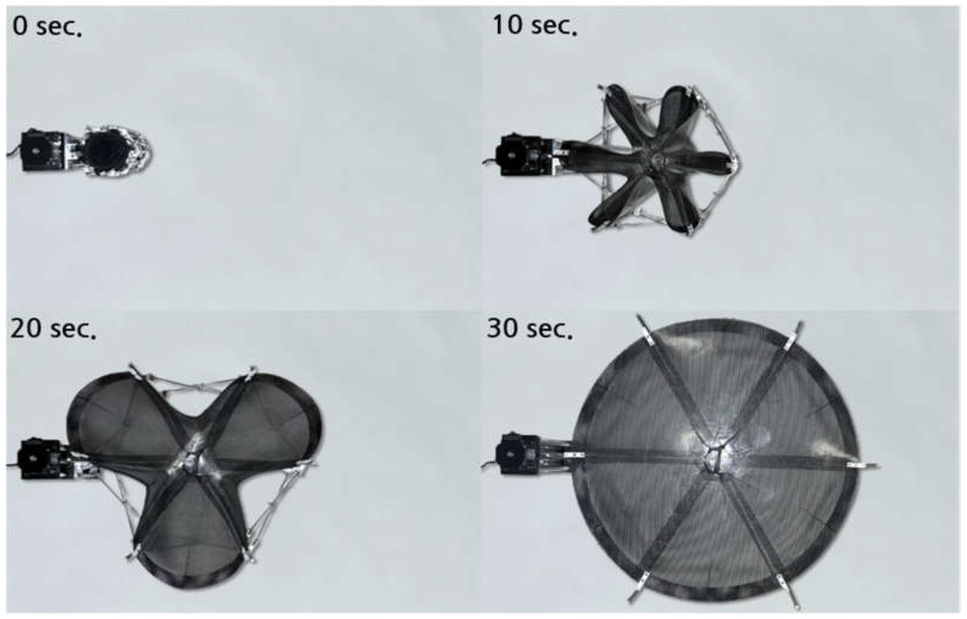
The deployment mechanism is designed to enable the flexible surface reflector to fold and unfold seamlessly without mechanical interferences. As illustrated in Figure 14, the conceptual deployment mechanism employs a six-unit extendable truss structure. The reflector is attached to the truss assembly without relying on tensioned support strings, requiring it to autonomously restore its designed parabolic shape through its inherent material elasticity. The deployment sequence of the extendable truss is depicted in Figure 15. The six-unit cells are synchronized with a single degree of freedom in vertical displacement during the unfolding process, ensuring a controlled and coordinated deployment. The deployment characteristics are experimentally evaluated under terrestrial gravity conditions. To precisely assess the kinematics behavior, the ARAMIS Digital Image Correlation (DIC) system is employed, enabling high-resolution and displacement measurements (Figure 16). Furthermore, a multibody dynamic analysis of the extendable truss structure is conducted using RecurDyn commercial software to simulate the deployment process. Figure 17 presents a comparative analysis of deployment characteristics obtained from both experimental and numerical simulations. The unfolding process is designed to complete within 30 seconds, and the variations in velocity and acceleration over time are illustrated. The acceleration asymptotically approaches zero due to position-controlled deployment facilitated by a linear motor. Minor discrepancies between the simulation and experimental results are attributed to frictional effects between components and ground contact. Nevertheless, a strong correlation between the experimental and numerical results is observed, validating the deployment dynamics of the proposed mechanism. Figure 18 illustrates the deployment procedure of the flexible surface reflector utilizing the extendable truss mechanism, demonstrating its sequential unfolding and structural recovery process.
5. Conclusions
A novel concept for a flexible surface reflector antenna has been demonstrated, highlighting its feasibility for spaceborne applications. The reflector utilizes a doubly curved flexible surface fabricated from a triaxially woven fabric-reinforced silicone (TWFS) composite. Unlike conventional membrane materials, TWFS composites do not require pretension when deployed as double-curved shell components, making them highly suitable for advanced deployable space structures. Experimental tensile tests on finite-size TWFS single-ply specimens reveal an anisotropic mechanical response, despite the quasi-isotropic nature of the fabric's weave pattern. This anisotropic behavior must be carefully considered in the design and structural optimization of the reflector surface to ensure deployment reliability and accurate surface conformance. Furthermore, the RF performance of the reflector has been tested and validated. Surface coating techniques aimed at enhancing the RF properties of TWFS composites are under investigation to enable high-frequency operational capabilities. The extendable truss deployment mechanism has been successfully demonstrated, accommodating a 0.6 m diameter parabolic reflector within a compact stowed volume, thereby optimizing space efficiency for satellite integration. The proposed design presents a structurally efficient and scalable solution for deployable reflector antennas in small satellite platforms, offering a pathway toward high-performance spaceborne communication systems.
Acknowledgments
This research is performed based on the cooperation with Korea Aerospace University – LIG Nex1 Cooperation.
References
- Rahmat-Samii, Y.; Manohar, V.; Kovitz, J.M. For Satellites, Think Small, Dream Big: A Review of Recent Antenna Developments for CubeSats. IEEE Antennas and Propagation Magazine 2017, 59, 22–30. [Google Scholar] [CrossRef]
- Hedgepeth, J.M. Accuracy Potentials for Large Space Antenna Reflectors with Passive Structure. Journal of Spacecraft and Rockets 1982, 19, 211–217. [Google Scholar] [CrossRef]
- Peral, E.; Tanelli, S.; Statham, S.; Joshi, S.; Imken, T.; Price, D.; Sauder, J.; Chahat, N.; Williams, A. RainCube: The First Ever Radar Measurements from a CubeSat in Space. Journal of Applied Remote Sensing 2019, 13, 032504. [Google Scholar] [CrossRef]
- Murphey, T.W.; William, F.; Bruce, D.; Juan, M. High Strain Composites. In Proceedings of the 2nd AIAA Spacecraft Structures Conference, Florida, USA, 2015. [Google Scholar]
- Datashvili, L.; Maghaldadze, N.; Baier, H.; Friemel, M.; Schmidt, L.D.R.; Luo, T. Enabling Technologies and Architectures at LSS GmbH for European Large Deployable and Reconfigurable Reflector Antennas; Deutscher Luft- und Raumfahrtkongress: Munich, Germany, 2017. [Google Scholar]
- Datashvili, L. Multifunctional and Dimensionally Stable Flexible Fibre Composites for Space Applications. Acta Astronautica 2010, 66, 1081–1086. [Google Scholar]
- Tan, L.T.; Pellegrino, S. Ultra Thin Deployable Reflector Antennas. In Proceedings of the 45th AIAA/ASME/ASCE/AHS/ASC Structures, Structural Dynamics & Materials Conference, 2004. [Google Scholar]
- Dufour, L.; Datashvii, L.; Guinot, F.; Legay, H.; Goussetis, G. “Origami Deployable Reflector Antenna for CubeSats. In Proceedings of the AIAA SciTech Forum, USA, 2021. [Google Scholar]
- Datashvili, L.; Baier, H.; Schmidt, L.R. Multi-scale Analysis of Structures Made of Triaxially Woven Fabric Composites with Stiff and Flexible Matrix Materials. In Proceedings of the 52nd AIAA/ASME/ASCE/AHS/ASC Structures, Structural Dynamics and Materials Conference, Colorado, 2011. [Google Scholar]
- Kueh, A.B.H.; Pellegrino, S. Thermo-elastic behavior of single ply triaxial woven fabric composites. In Proceedings of the 47th AIAA/ASME/ASCE/AHS/ASC Structures, Structural Dynamics, and Materials Conference, 2006. [Google Scholar]
- Kueh, A.B.H.; Soykasap, O.; Pellegrino, S. Thermo-Mechanical Behavior of Single-Ply Triaxial Weave Carbon Fiber Reinforced Plastic. Triaxial Structures, 2005. [Google Scholar]
- ASTM D638; Standard test method for tensile properties of plastics. ASTM International: West Conshohocken, PA, 2014.
- Aramis 3D strain measurement system. Available online: http://www.gom.com/de/messsysteme/ systemuebersicht/aramis.html.
- Kueh, A.; Pellegrino, S. Triaxial Weave Fabric Composites. European Space Agency Contractor Report. 2007. [Google Scholar]
- Gao, J.; Chen, W.; Yu, B.; Fan, P.; Zhao, B.; Hu, J.; Zhang, D.; Fang, G.; Peng, F. A multi-scale method for predicting ABD stiffness matrix of single-ply weave-reinforced composite. Composite structures 2019, 230, 111478. [Google Scholar] [CrossRef]
- Tian, W.; Qi, L.; Chao, X.; Liang, J.; Fu, M. Periodic boundary condition and its numerical implementation algorithm for the evaluation of effective mechanical properties of the composites with complicated micro-structures. Composites Part B: Engineering 2019, 162, 1–10. [Google Scholar]
- Cheng, Q. Fiber-Reinforced Composites; Nova Science Publishers, Inc., 2011; pp. 612–615. [Google Scholar]
- Yoon, S.S.; Lee, J.W.; Lee, T.K.; Roh, J.H. Insensitivity Characteristics in the Dual Polarization of Deployable CFRP Reflector Antennas for SAR. IEEE Transactions on Antennas and Propagation 2018, 66, 88–95. [Google Scholar] [CrossRef]
Figure 1.
Fabricated TWFS Composite.
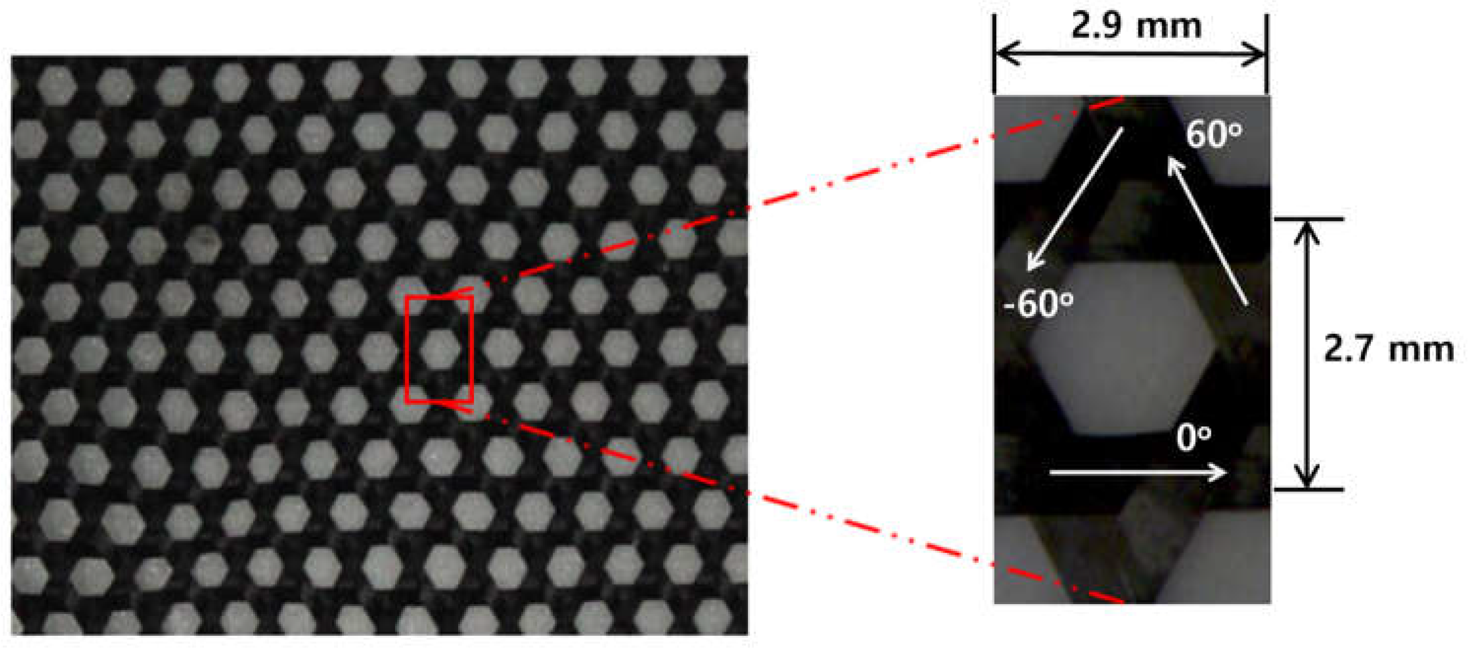
Figure 2.
Experimental Setup for Tensile Test.
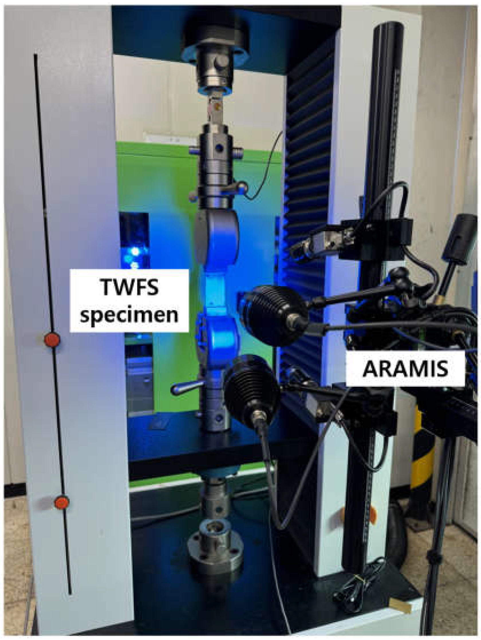
Figure 3.
Numerical Model of TWFS.
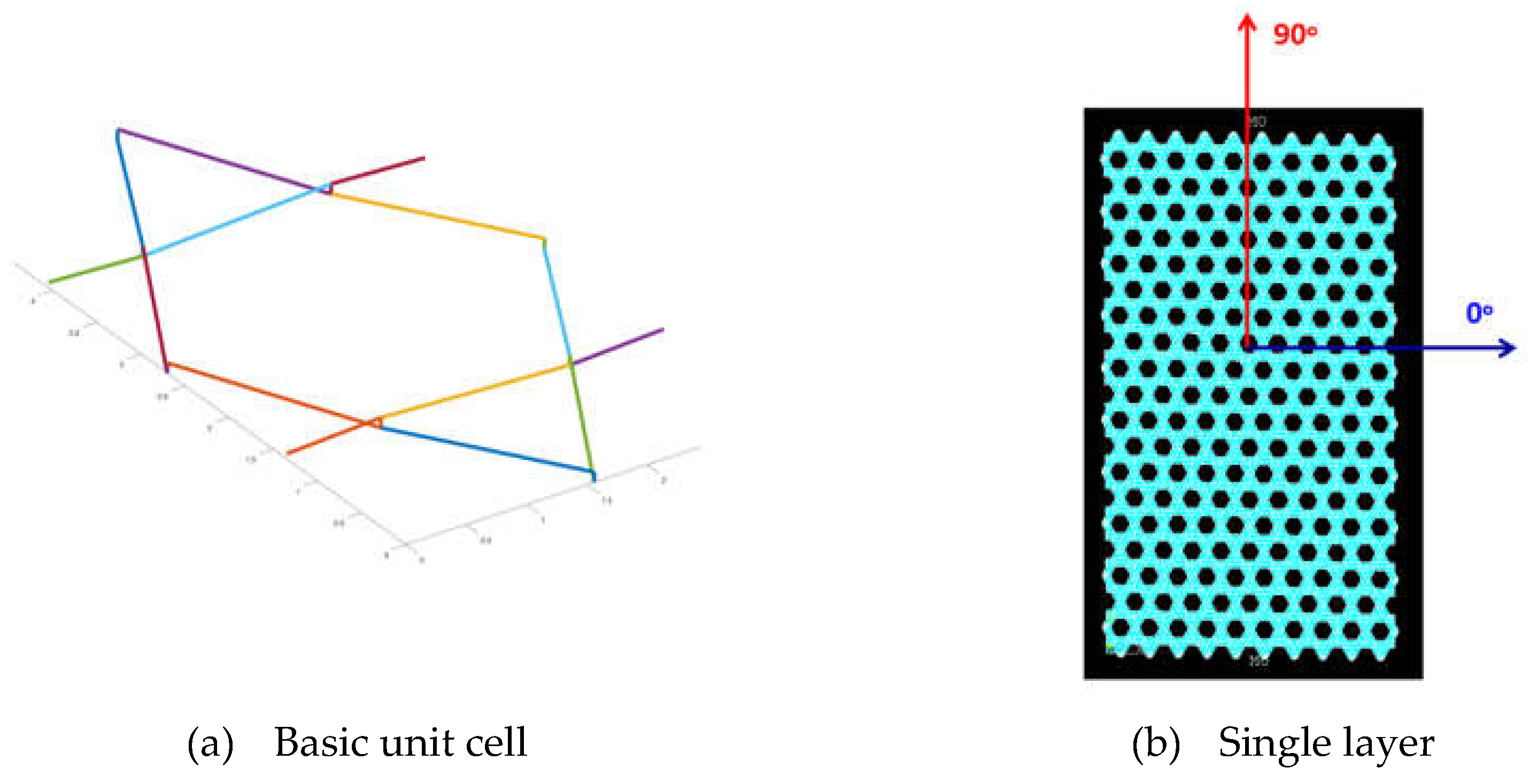
Figure 4.
Stress-strain Curves with Fabric Direction.
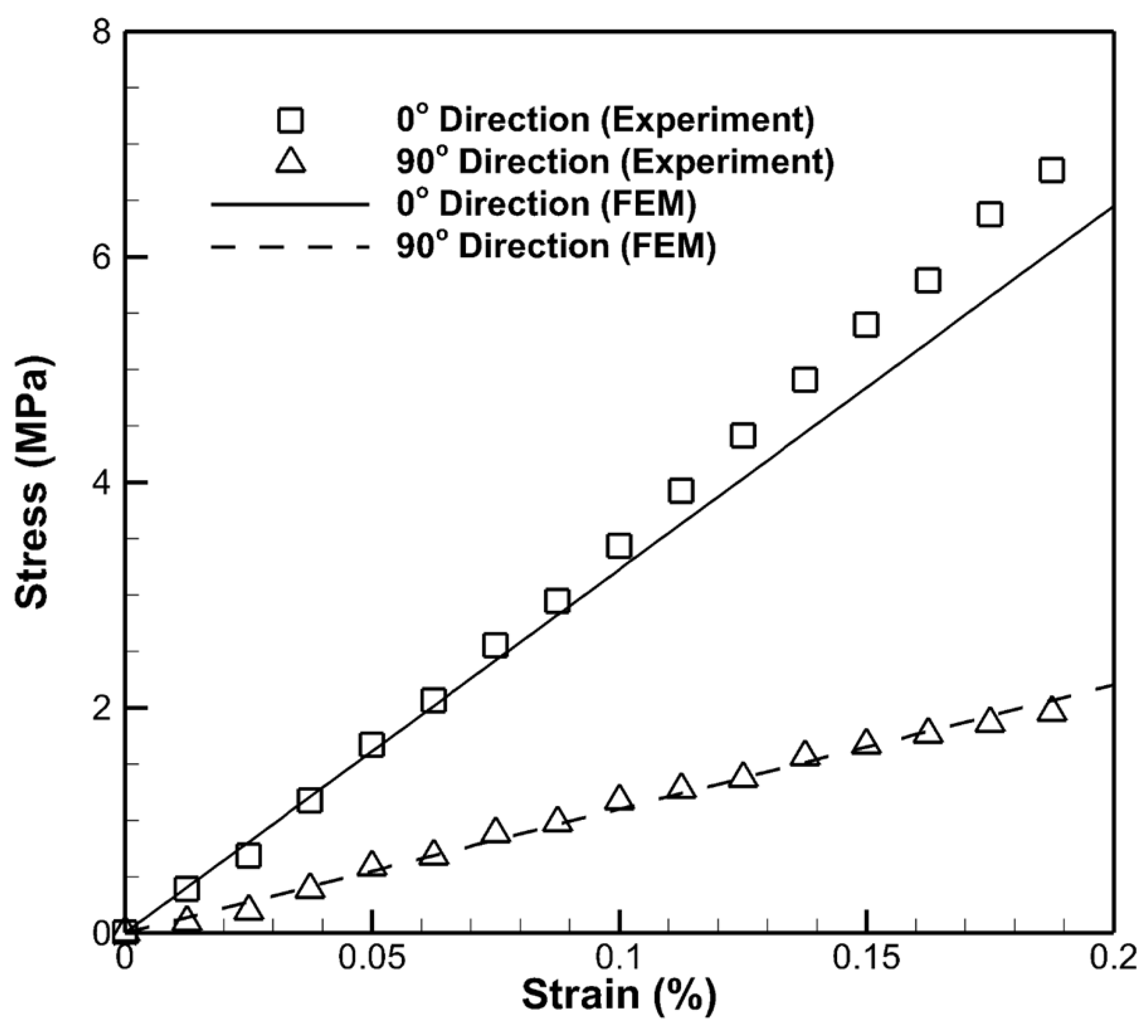
Figure 5.
Tensile Test Results with Aspect Ratio.
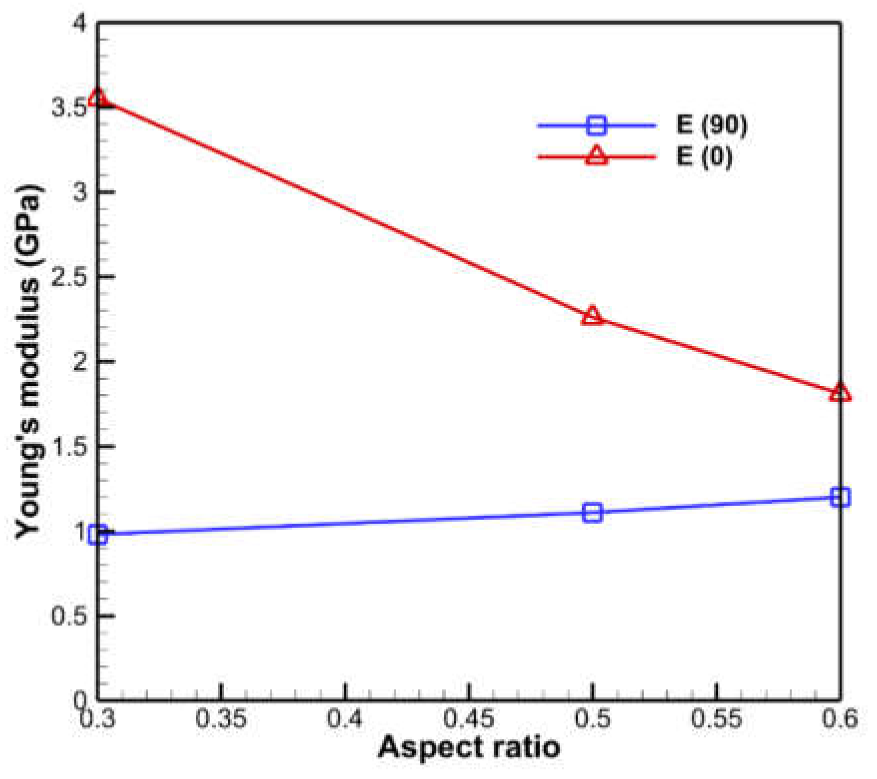
Figure 6.
Deformed Shape of the Specimen in 90° direction.
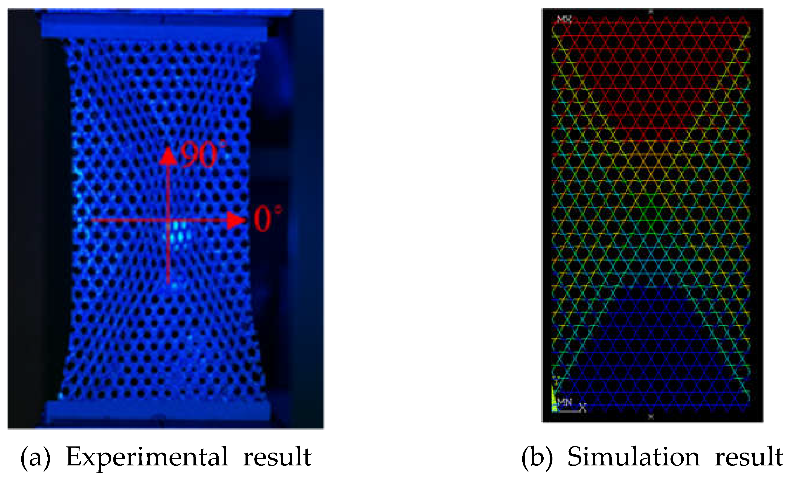
Figure 7.
Test Setup for Waveguide Measurements.
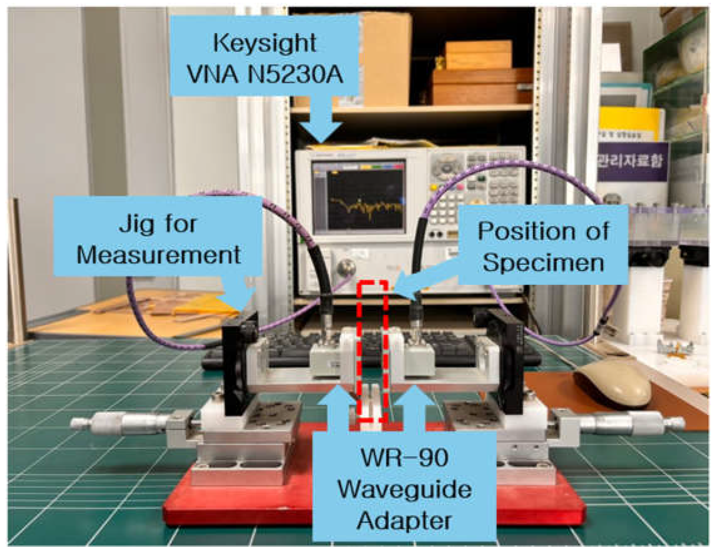
Figure 8.
Reflection Coefficient and Equivalent Electrical Conductivity.
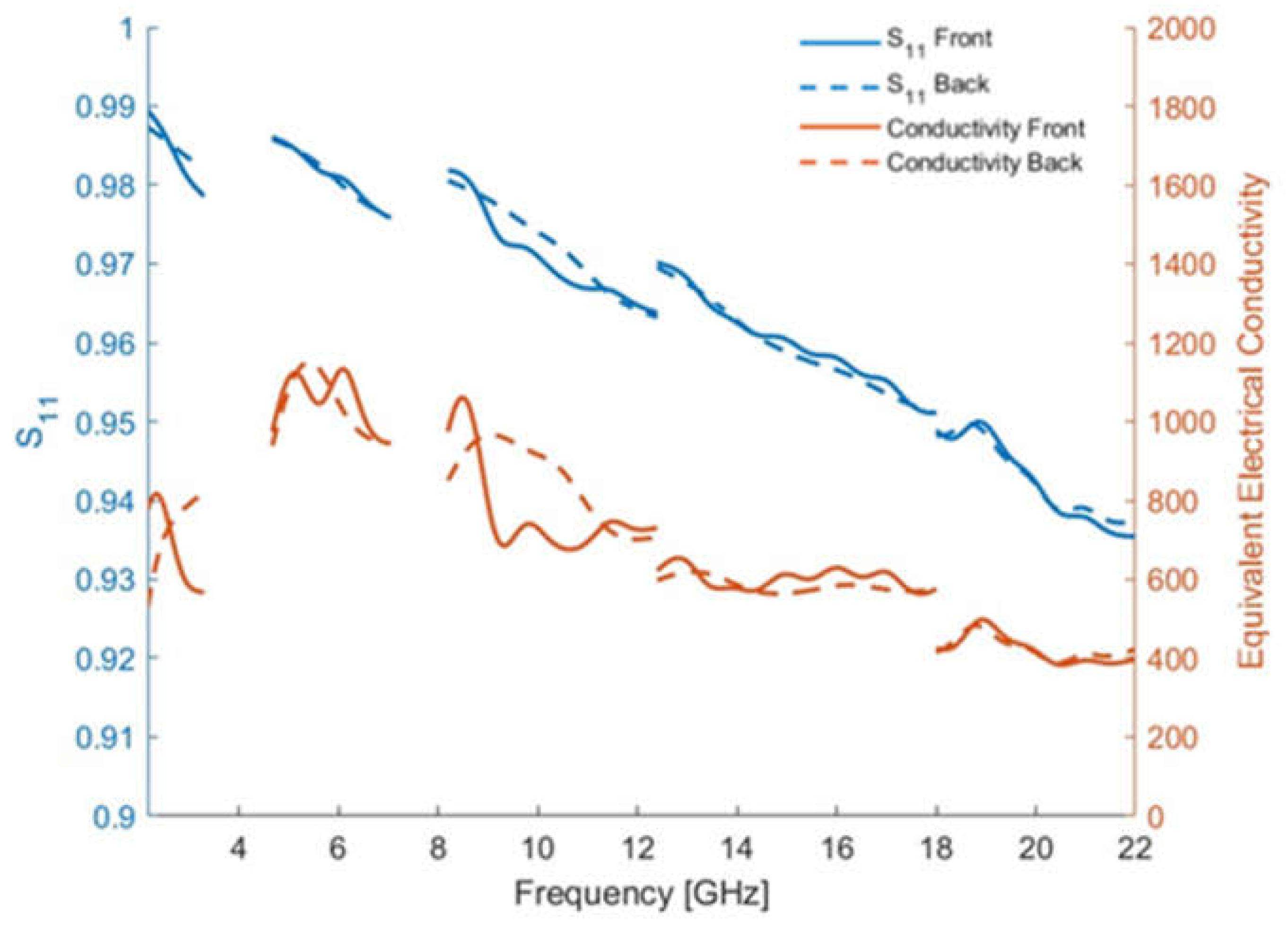
Figure 9.
Test Model of Reflector Antenna.
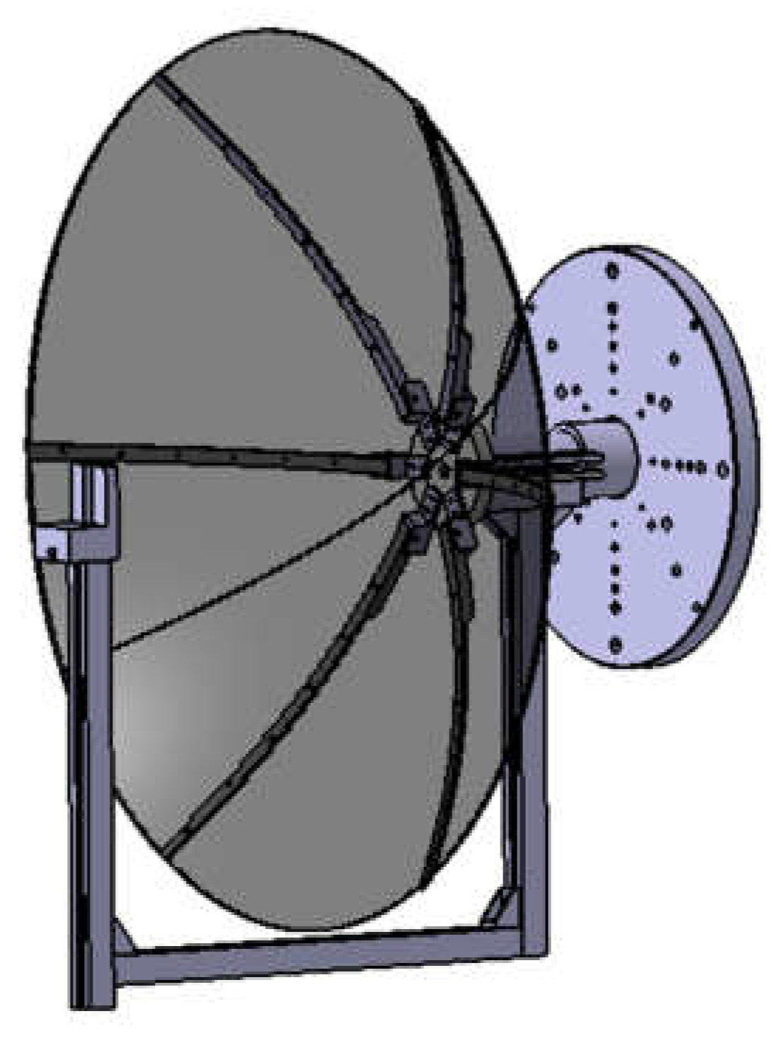
Figure 10.
Surface Error Measurement.
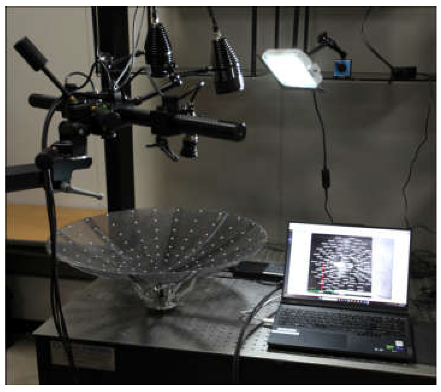
Figure 11.
Experimental Measurement of Surface Error.
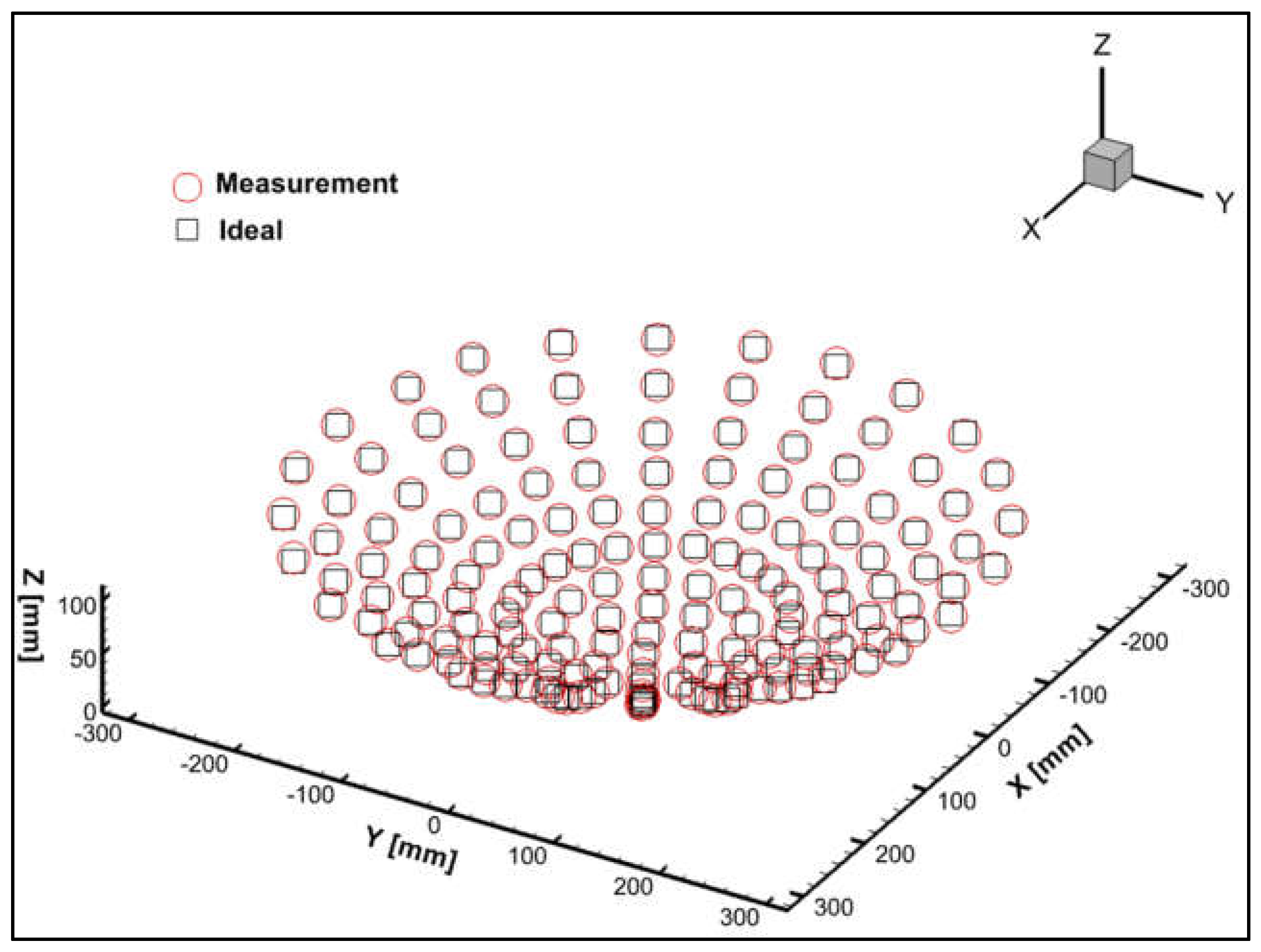
Figure 12.
Reflector Antenna in Near-field Test.
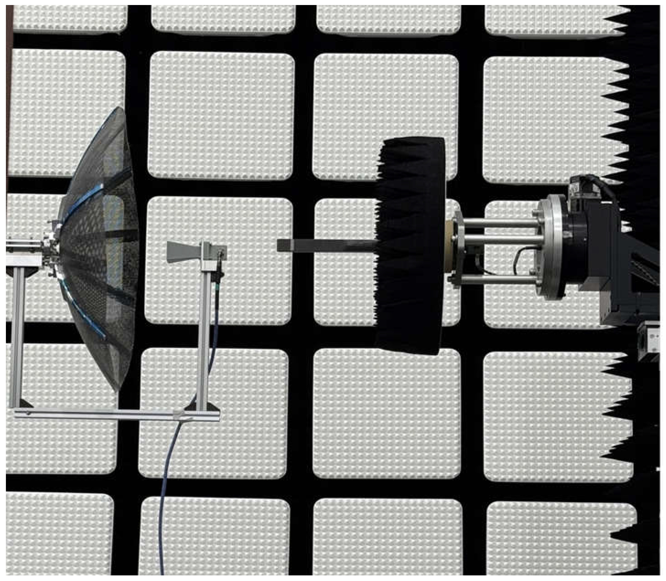
Figure 13.
Comparisons of the Reflector Antenna Patterns.
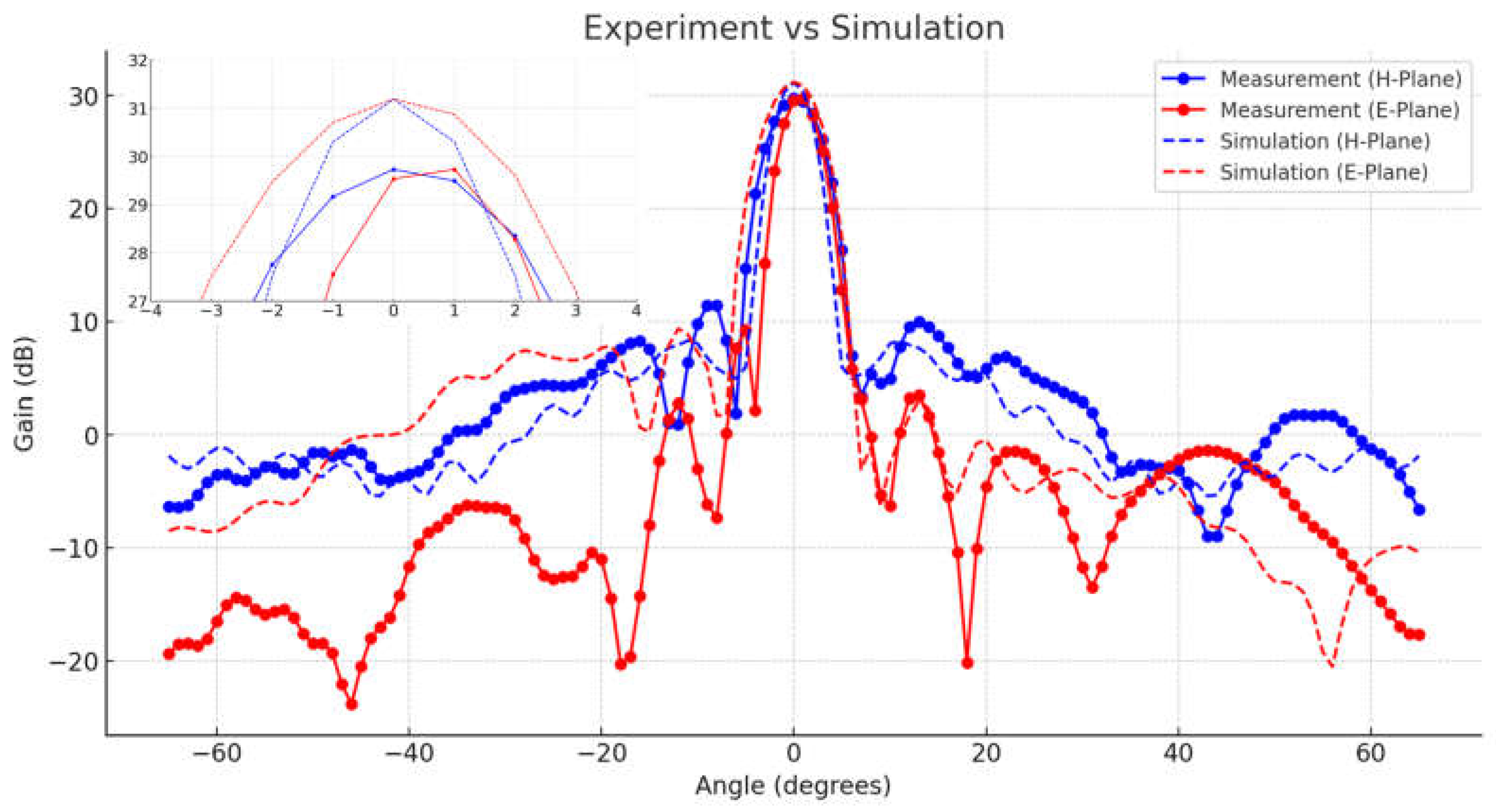
Figure 14.
Extendable Truss Deployment Mechanism.
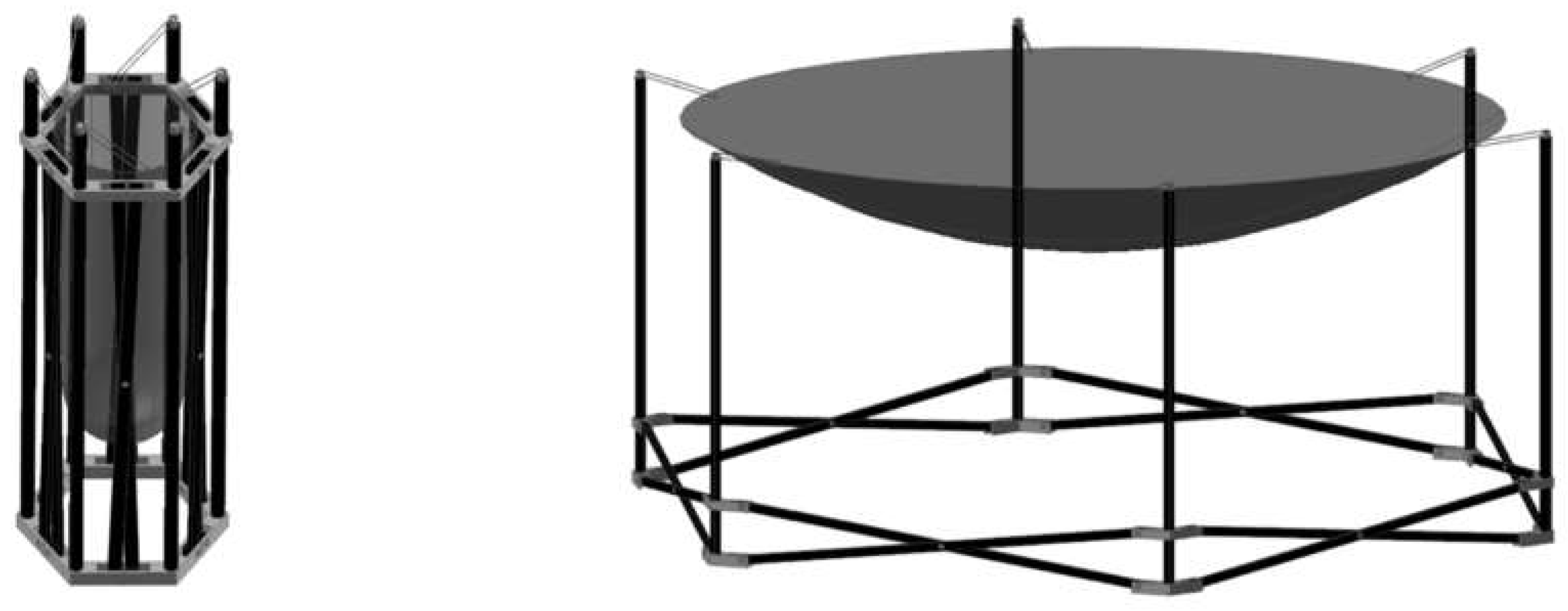
Figure 15.
Simulation of Deployment Procedure.
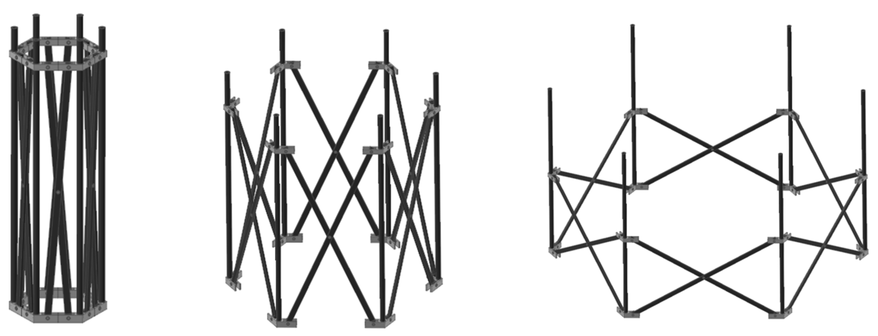
Figure 16.
Experimental Setup for Deployment Characteristics.
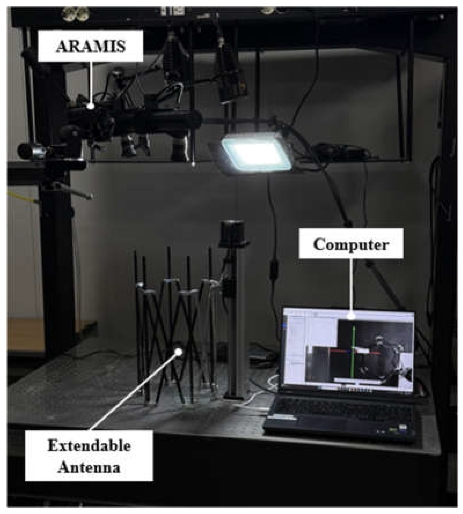
Figure 17.
Comparisons of Deployment Characteristics.
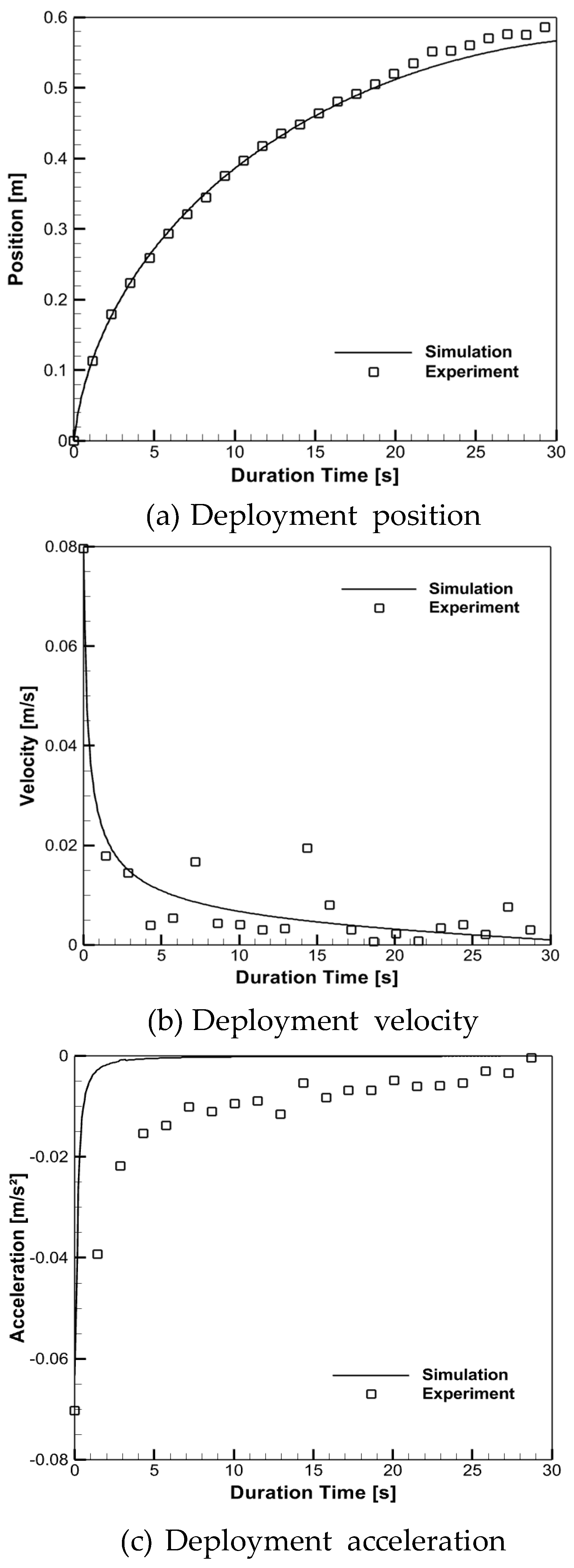
Figure 18.
Deployment Procedure of the Reflector.
Disclaimer/Publisher’s Note: The statements, opinions and data contained in all publications are solely those of the individual author(s) and contributor(s) and not of MDPI and/or the editor(s). MDPI and/or the editor(s) disclaim responsibility for any injury to people or property resulting from any ideas, methods, instructions or products referred to in the content. |
© 2025 by the authors. Licensee MDPI, Basel, Switzerland. This article is an open access article distributed under the terms and conditions of the Creative Commons Attribution (CC BY) license (http://creativecommons.org/licenses/by/4.0/).
Copyright: This open access article is published under a Creative Commons CC BY 4.0 license, which permit the free download, distribution, and reuse, provided that the author and preprint are cited in any reuse.


