
Submitted:
30 June 2025
Posted:
01 July 2025
You are already at the latest version
Abstract
Orbital Angular Momentum (OAM) beams exhibit divergence during transmission, which constrains the channel capacity of communication systems. To address these challenges, Intelligent Reflecting Surfaces (IRS), which can independently manipulate incident electromagnetic waves by adjusting their amplitude and phase, are employed to construct IRS-assisted OAM communication systems. By introducing additional information pathways, IRS enhances diversity gain. We studied the simulations of two placement methods for the IRS: arbitrary placement and standard placement. In the case of arbitrary placement, the beam reflected by the IRS can be decomposed into different OAM modes, forming a diversity reception power corresponding to each OAM mode component. This improves the signal-to-noise ratio (SNR) at the receiver, thereby enhancing channel capacity. In particular, when the IRS is symmetrically and uniformly positioned at the center of the main transmission axis, its elements can be approximated as a uniform circular array. This configuration can not only achieve optimal reception along the direction of the maximum gain of the orbital angular momentum beam, but also reduce the antenna radius required at the receiver to half or even smaller.
Keywords:
Intelligent reflecting surfaces
; orbital angular momentum
; near-field communications
; channel capacity
1. Introduction
Recently, the IRS has become one of the candidate technologies in the 6-th Generation (6G) communications [1]. An IRS is modeled as an array of passive reflecting elements, each capable of independently applying a phase shift to incident electromagnetic (EM) waves to facilitate various communication objectives [2,3,4,5]. In general, IRSs can be categorized into active and passive types based on their power consumption. For traditional communication systems, IRS can not only build an effective information transmission path when the transmitter and receiver are blocked, but also transmit energy to enhance the transmission effect of the MIMO system [6]. The channel model of an IRS-assisted communication mechanism incorporates the signal path introduced by the IRS-reflected beam, thereby enhancing the system’s degrees of freedom [7]. In this mechanism, the direct path and the reflection path both carry the same information, then they can be superimposed at the terminal to improve signal quality. In addition, IRS can assist communication systems in channel estimation and secure communication tasks [10]. Its flexible deployment allows it to seamlessly integrate existing infrastructure into the communication network, enhancing system adaptability and efficiency [11].
Orbital Angular Momentum (OAM) can also be regarded as a potential core key technology [12]. Generally speaking, OAM can be generated by Uniform Circular Array (UCA) antennas, which is expected to be implemented for large capacity communications [17]. However, the all phase plane coaxial receiving in the OAM transmission enjoys a high capacity but requires strict alignment and large receiving antenna size [19]. Due to the beam divergence, the distance is a critical issue before it can be applied, which is a challenging problem [20]. Hence, the general circular array has been proposed to cover a large phase plane physically with self-alignment and no restriction in the antenna distribution within the array [21]. In addition, a dedicated parabolic antenna can also be used to converge the OAM beam to further increase the transmission distance [22]. The above two methods are to increase the performance by changing the structure of the antenna. The emergence of IRS provides a new idea for increasing the performance by adding the channel path.
Based on the nature of IRS enhancing the traditional communication system, it is hoped to construct an IRS-assisted OAM transmission mechanism to alleviate the divergence problem in the OAM-based communications. IRS has been utilized to provide additional access for OAM wireless links when the Line of Sight (LOS) path is blocked [23]. In this paper, an IRS-assisted OAM communication system in the presence of a LOS path is studied and the mathematical model is established. Furthermore, IRS-assisted OAM transmission is evaluated in detail.
2. System Architecture
A large-capacity point-to-point data transmission link is established by multiplexing the OAM wave between the macro BS and the Self-Backhaul Small Cell (SBSC) station, and the IRS is used to assist the transmission. The system structure is shown in Figure 1. The BS sets up a large-scale phased array antenna and radiates the OAM beam with mode l by adjusting the phase of the vibrator in the phased array antenna, then the information is transmitted to the SBSC station via the IRSs and direct path. A single IRS consists of small reflective elements spaced apart and distributed on the transmission path. In this case, the transmission path introduced by the IRS will appear between the BS and the SBSC station. When the IRS assists the OAM communication system, it can be single or multiple. The SBSC station at the receiving end uses the UCA with a radius of . The received signal is digitally processed and restored, and then transmitted to the user end.
As shown in Figure 1, the macro BS is connected with IRSs by wireless methods. Furthermore, after the OAM waves reach the IRS array, one of the IRSs in the array adjusts the amplitude and phase of the waves to reflect them towards the UE. Similarly, the beams can be reflected by the IRSs, respectively. Note that the scheme of the macro BS antenna is not the UCA structure, but the Phased Array Antenna generates multiple shaped beams pointing to the SBSC station. As a special case, when multiple IRSs are distributed symmetrically in the center of the OAM transmission main axis, the IRS array can be directly equivalent to a coaxial multi-ring UCA with a large radius. Therefore, the beam radiated by the IRS equivalent UCA and the beam generated by the BS phased array antenna can be directly added.
3. Mathematical Model
3.1. Channel Model with IRS
After all the OAM waves are reflected by the IRS, the signal received by the SBSC station can be expressed as:
where is the complex signal on the UCA transmitter antenna , is the channel response from the BS to the i-th IRS. is the phase shift matrix of the i-th IRS and . represents the phase shift values of the corresponding elements in the i-th IRS. is the channel from the i-th IRS to the SBSC, is the channel response from the i-th element of transmit antenna to the SBSC, is a Gaussian white noise vector with dimensions . The total signal received by the UCA at the receiving end can be divided into two parts. One is the OAM beam signal reflected by the IRS and the other is the OAM signal directly received under the LOS channel. When the IRS is arbitrarily distributed, the former can be understood as a traditional MIMO signal. The sum of the signals is the superposition of the traditional MIMO signal and the OAM signal. The OAM channel characteristics assisted by IRS are analyzed. Simultaneously left-multiply both sides of Eq. (1) by the matrix .
where represents a block diagonal matrix and denotes the Hermitian transpose. According to the channel characteristics of OAM, the LOS path in the channel formula is directly changed to a diagonal matrix, and the channel formula for transmitting information according to OAM is obtained. The channel state information (CSI) of the entire communication system for IRS-assisted OAM transmission can be estimated [8]. When all CSI at the originating end is known, it can be seen from Eq. (2) that the assistant channel brought by the introduction of IRS is added in the OAM information transmission process, which means that the degree of freedom of the entire OAM communication system becomes higher. The configuration of the IRS can increase the channel capacity of the transmission system. At the same time, because of the introduction of IRS, the received signal strength and SNR at the receiving end will increase.
3.2. Capacity Optimization of the OAM System with IRS
According to information theory, the sum capacity of the OAM system with IRS in Eq. (2) is given by the mutual information rate . Therefore, configuring the phase shift matrix of the IRS to achieve optimal beamforming and maximize the channel capacity of the IRS-assisted OAM communication system is the first problem to be solved. After that, recovering the received signal according to the downlink signal is the problem after the data transmission. The channel capacity of the entire IRS-assisted OAM transmission system can be expressed as
where P is the total transmission power, N denotes the number of OAM modes, B denotes the bandwidth, and is the variance of the noise.
When the CSI of the IRS-assisted OAM system is known, the final optimization problem can be expressed as
The optimization problem in Eq. (8) aims to optimize to maximize the value of the component in the desired OAM mode during transmission. Then the maximum diversity power is obtained, and the capacity reaches its maximum value. The optimization problem of Eq. (8) can be transformed into a quadratically constrained quadratic program (QCQP) and can be solved by the majorization-minimization (MM) algorithm proposed in [9]. Then the solution of can be given, which can make IRS achieve better beamforming.
3.3. A Special Case of IRS Aided OAM System
When each IRS is symmetrically distributed on the transmission path with the z-axis as the center, the elements in the a-th row and the b-th column in the i-th IRS and the elements on other IRS are co-circular to form the v-th equivalent UCA. The phase distribution in space meets the conditions for generating OAM beams. At this time, after reasonable adjustment by the IRS, the beams reaching the user end through the IRS are also OAM beams, which becomes a special case of OAM beam transmission. In order to make the OAM beam received by the SBSC in the LOS superimpose with the signal through the IRS. All elements in the same circle have the same amplitude and compensate for phase differences on the path through the IRS and in the direct path. At this time, and in Eq. (2) are both cyclic symmetric Fourier matrices, i.e.,
is the received OAM signal from the BS to the receiving end user, i.e.,
For the transmitter, when using UCA to generate an OAM beam, the OAM beam can be expressed as [24]
where is the radius of the phased array antenna when it is equivalent to UCA to generate OAM waves. n denotes the n-th channel of OAM modes, denotes the OAM mode number, is a spiral phase factor related to the azimuth angle , which determines the periodic variation of the OAM spiral phase plane, denotes the -order Bessel function, is the divergence angle of the OAM beam, is the signal propagation factor for each OAM channel, N is the elements number of the antenna, d denotes the wave path, i is the imaginary unit, is the amplitude of each OAM signal. Assuming that the distance from point to BS is , the distance from point to SBSC is , and the angle between the BS to the element in the a-th row and the b-th column of the i-th IRS and the z-axis is . The phase term of the element in the a-th row and b-th column of the i-th IRS is , the vertical distance between the IRS and the z-axis is , and the spacing between the elements of IRS is .
The distance from the BS to the element in the a-th row and the b-th column of the i-th IRS is
where and .
The electric field intensity of the element in the a-th row and the b-th column of the i-th IRS receiving the OAM beam emitted by the BS can be expressed as
The electric field strength of the OAM beam generated by the v-th equivalent UCA in the IRS reaching the p-th antenna at the SBSC can be expressed as
where is the radius of the equivalent UCA. The total electric field strength received by the p-th antenna is
It can be clearly seen that the complexity of the digital demodulation of the receiver remains unchanged, and the strength of the signal received by the receiver increases.
4. Figures and Tables
4.1. Simulation with IRS Random Placement
To demonstrate the advantages of an IRS-assisted OAM communication system over a traditional OAM system without IRS in terms of channel capacity improvement, simulations are conducted for the passive case. Specifically, the channel capacity is analyzed for scenarios with and without IRS when the receiver employs a UCA with varying radii. The specific parameters of the OAM transmission simulation with randomly placed IRS are listed as follows. The working frequency is 10 GHz. The distance between the BS and the SBSC is 50 m, the number of IRSs is 30, the number of elements on each IRS is 16, and the vertical distance between the IRS and the transmission main axis is 1 m. The phased array antenna at the transmitter, which follows the form of UCA with a radius of m, feeds the phase on the elements and generates OAM. Assuming that the IRS is randomly distributed on the transmission path, then four OAM modes are multiplexed to transmit information. The radius of the UCA at the receiving end is selected as m, m, and m respectively.
The simulation results are shown in Figure 2. It can be clearly seen that the IRS-assisted OAM system can increase the channel capacity. When the receiving radius is the same, compared with the traditional OAM system, the OAM system constructed with IRS can increase the channel capacity by about 1 bit/s/Hz when the SNR at the SBSC is about 20 dB. The IRS is passive which makes the signal reaching the receiver after the IRS converge to suffer a large path attenuation, so the improvement of the channel capacity is not significant. Nonetheless, the OAM system with passive IRS can still be used for the OAM communication system with high SNR.
4.2. Simulation in Special Case with IRS Center Symmetrical
Considering the IRS assisting OAM transmission in special scenarios, it is assumed that the placement of the IRS is not affected by the environment. It can be placed centrally symmetrically and is equivalent to a larger radius UCA. At this time, the BS generates OAM wave with a mode of l. In order to maximize the energy received by the IRS, the IRS is placed along the main beam direction of the OAM wave, and the receiver of the SBSC is also along the OAM main beam generated by the equivalent UCA. When placing the IRS and the SBSC station according to the above method, the distance between the IRS and the BS is set to 100 m, the number of IRSs is 10, and the number of internal elements is 16. The radius of BS antenna is set from m to m. In order to generate an OAM beam, the distances between the IRS and the BS and between the IRS and the SBSC need to meet the far-field conditions. In the cases of achieving the receiving effect along the OAM main beam direction with and without the assistance of a passive IRS, Figure 3 shows the relationship between the UCA radius required by the receiver to achieve the same received energy and the BS antenna radius . For simplicity, only the assistance of the passive IRS is considered.
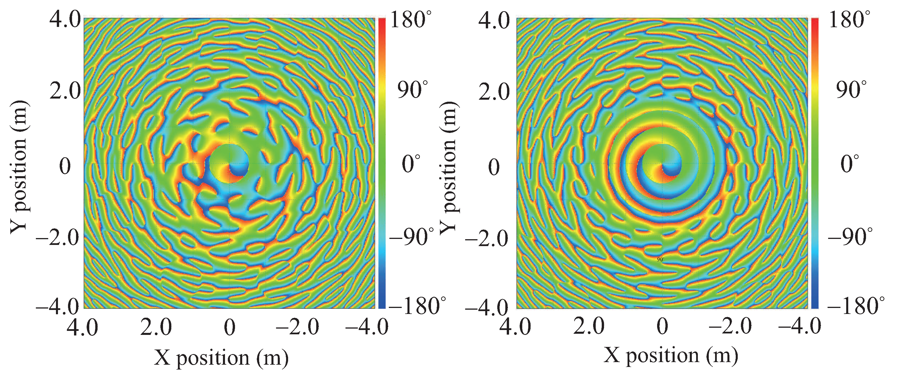
When the passive IRS is used to achieve the same received energy within the range of the selected transmitting antenna , the antenna size of the SBSC only needs to be half or even less than the original size. IRS achieves the effect of converging OAM beams. However, due to the large radius of the UCA equivalent to the IRS, the number of elements constituting the UCA will affect the generation of the OAM beam, and the effective range of maintaining the vortex phase characteristics will be changed. As a special case, when and 16, the phase distribution of OAM is shown in Figure 4 by Feko simulation to illustrate the influence of the number of on the effective vortex range. The UCA radius equivalent to IRS is 1 m. It can be clearly seen that the larger the number of , the larger the effective vortex range. When the is small, the effective vortex range becomes smaller due to the influence of the grating lobe effect.
It is concluded from the simulation results that the introduction of the IRS enables the receiving end to have the same or even greater received signal energy than receiving along the main direction of the OAM beams generated by the BS in the case of a small radius. In addition, when the number of elements N remains unchanged, the increase of UCA radius will reduce the beam width of the main lobe and reduce the range of spatial elevation angle to maintain the OAM vortex characteristics, but the reception in the main beam direction will not be affected by the grating lobe effect, which provides a theoretical basis for the feasibility of using IRS to assist in the transmission of OAM beams.
5. Conclusion
The IRS-assisted OAM communication system is based on the principle that the signal components generated by the IRS construction path can be expanded to each mode, and then contribute to the transmission mode, so as to obtain the enhanced transmission of OAM. Finally, the effect of increasing the transmission distance, improving channel capacity and reducing the size of the receiver is achieved. IRS-assisted OAM communication system transmission is equivalent to adding a new information path in the case of LOS. Its most intuitive advantage is that the channel capacity of the entire communication system is improved. When the IRS is placed symmetrically and evenly on the transmission path, it can be equivalent to a coaxial multi-ring UCA. The IRS-assisted OAM communication system in this special case will converge the OAM wave. Its most intuitive advantage is effectively shortening the antenna size.
Author Contributions
The authors confirm contribution to the paper as follows: Conceptualization, Qiuli WU and Yufei ZHAO; methodology, Qiuli WU and Yufei ZHAO; software, Qiuli WU, Shicheng Li1 and Yiqi Li1; validation, Yufei ZHAO; formal analysis, Yufei ZHAO, Deyu LIN; resources, Qiuli WU; data curation, Shicheng Li1 and Yiqi Li1; writing—original draft preparation, Qiuli WU; writing—review and editing, Yufei ZHAO and Deyu LIN; visualization, Shicheng Li1 and Yiqi Li1; supervision, Qiuli WU and Yufei ZHAO; project administration, Qiuli WU and Yufei ZHAO; funding acquisition, Qiuli WU and Yufei ZHAO. All authors reviewed the results and approved the final version of the manuscript.
Funding
This work was supported in part by the National Research Foundation, Singapore and Infocomm Media Development Authority under its Future Communications Research & Development Programme, Grant No. FCP-NTU-RG-2024-025, in part by Imperial-NTU Collaboration Fund, No. INCF-2025-005.
Conflicts of Interest
The authors declare no conflicts of interest.
References
- H. Guo, Y. Liang, J. Chen and E. G. Larsson, “Weighted sum-Rate maximization for reconfigurable intelligent surface aided wireless networks," IEEE Trans. Wirel. Commun.2020, 19(5), pp. 3064–3076. [CrossRef]
- Q. Wu and R. Zhang, “Towards smart and reconfigurable environment: Intelligent reflecting surface aided wireless network,” IEEE Commun. Mag.2020, 58(1), pp. 106–112. [CrossRef]
- Y. Zhao, etal., “2-Bit RIS prototyping enhancing rapid-response space-time wavefront manipulation for wireless communication: Experimental studies,” IEEE Open Journal of the Communications Society2024, 5, pp. 4885–4901. [CrossRef]
- Y. Li, etal., “A Novel Design of Varactor-Based RIS: Achieving Low-Profile, Wideband, and Continuous Phase Control,” IEEE Antennas and Wireless Propagation Letters2025. [CrossRef]
- Y. Zhao, etal., “Holographic-inspired meta-surfaces exploiting vortex beams for low-interference multipair IoT communications: From theory to prototype,” IEEE Internet of Things Journal2024, 11(7), pp. 12660–12675. [CrossRef]
- S. Zhang and R. Zhang, “Capacity characterization for intelligent reflecting surface aided MIMO communication," IEEE J. Sel. Areas Commun.2020, 38(8), pp. 1823–1838. [CrossRef]
- L. Dong and H. -M. Wang, “Enhancing secure MIMO transmission via intelligent reflecting surface," IEEE Trans. Wirel. Commun.2020, 19(11), pp. 7543–7556.
- Z. He and X. Yuan, “Cascaded channel estimation for large intelligent metasurface assisted massive MIMO," IEEE Wireless Commun. Lett.2020, 9(2), pp. 210–214. [CrossRef]
- W. Yan, X. Yuan, Z. Q. He and X. Kuai, “Passive beamforming and information transfer design for reconfigurable intelligent surfaces aided multiuser MIMO systems,” IEEE J. Sel. Areas Commun.2020, 38(8), pp. 1793–1808. [CrossRef]
- Z. Wang, L. Liu and S. Cui, “Channel estimation for intelligent reflecting surface assisted multiuser communications: Framework, algorithms, and analysis,” IEEE Trans. Wirel. Commun.2020, 19(10), pp. 6607–6620.
- Q. Wu, S. Zhang, B. Zheng, C. You and R. Zhang, “Intelligent reflecting surface-aided wireless communications: A tutorial,” IEEE Trans. Wirel. Commun.2021, 69(5), pp. 3313-3351. [CrossRef]
- L. Allen, M. W. Beijersbergen, R. J. C. Spreeuw, and J. P. Woerdman, “Orbital angular momentum of light and the transformation of Laguerre-Gaussian laser modes,” Phys Rev A1992, 45(11). [CrossRef]
- Q. B. Zhu, T. Jiang, D. M. Qu, D. Chen, N. R. Zhou, “Radio vortex multiple-input multiple-output communication systems with high capacity,” IEEE Access2015, 3, pp. 2456–2464. [CrossRef]
- K. Yuri, N. Honma and K. Murata, “Mode selection method suitable for dual-circular-polarized OAM transmission,” IEEE Trans. Antennas Propag.2019, 67(7), pp. 4878–4882. [CrossRef]
- N. Zhao, X. Li, G. Li, and J. M. Kahn, “Capacity limits of spatially multiplexed free-space communication,” Nature Photon.2015, pp. 822–826. [CrossRef]
- Y. Zhao, et al. Near-orthogonal overlay communications in LoS channel enabled by novel OAM beams without central energy voids: An experimental study. IEEE Internet of Things Journal2024, 11(24), pp. 39697–39708. [CrossRef]
- B. Thidé, etal., “Utilization of photon orbital angular momentum in the low-frequency radio domain,” Phys. Rev. Lett.2007, 99(8), pp. 087701. [CrossRef]
- S. M. Mohammadi, etal., “Orbital angular momentum in radio-A system study,” IEEE Trans. Antennas Propag.2010, 58(2), pp. 565–572.
- C. Zhang and Y. Zhao, “Orbital angular momentum nondegenerate index mapping for long fistance transmission,” IEEE Trans. Wirel. Commun.2019, 18(11), pp. 5027–5036. [CrossRef]
- D. K. Nguyen, O. Pascal, J. Sokoloff, A. Chabory, B. Palacin, and N. Capet, “Antenna gain and link budget for waves carrying orbital angular momentum,” Radio Sci.2015, 50(11), pp. 1165–1175. [CrossRef]
- Y. Zhao and C. Zhang, “Distributed antennas scheme for orbital angular momentum long-distance transmission,” IEEE Antennas Wireless Propaga. Lett.2020, 19(2), pp. 332–336. [CrossRef]
- Q. Wu, X. Jiang, and C. Zhang, “Attenuation of Orbital Angular Momentum Beam Transmission with Parabolic Antenna,” IEEE Antennas Wireless Propaga. Lett.2021, 20, pp. 1849–1853. [CrossRef]
- Y. Li, M. Jiang, G. Zhang and M. Cui, “Achievable rate maximization for intelligent reflecting surface-assisted orbital angular momentum-based communication systems,” IEEE Trans. Veh. Technol.2021, 70(7), pp. 7277–7282. [CrossRef]
- K. Liu, etal., “Generation of OAM beams using phased array in the microwave band,” IEEE Trans. Antennas Propag.2016, 64(9), pp. 3850–3857. [CrossRef]
Figure 1.
The OAM communication system assisted by IRS.
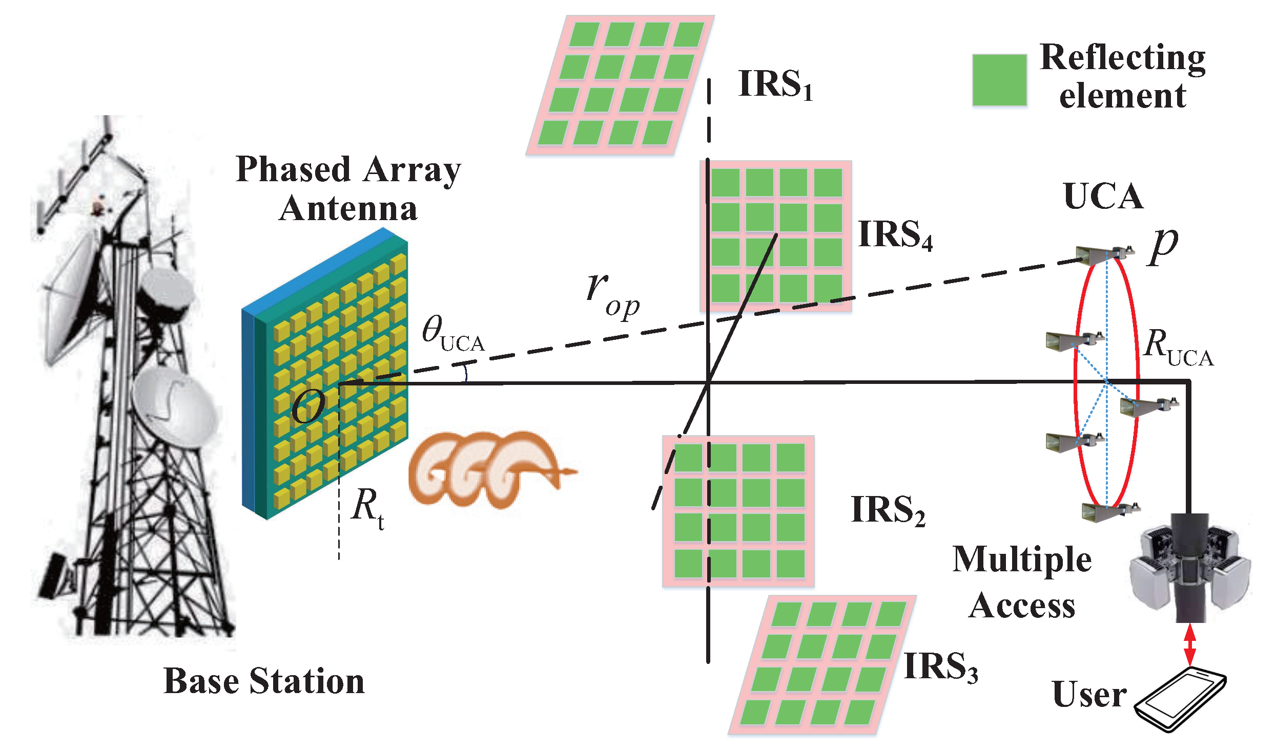
Figure 2.
The channel capacity with IRS and without IRS in passive case.
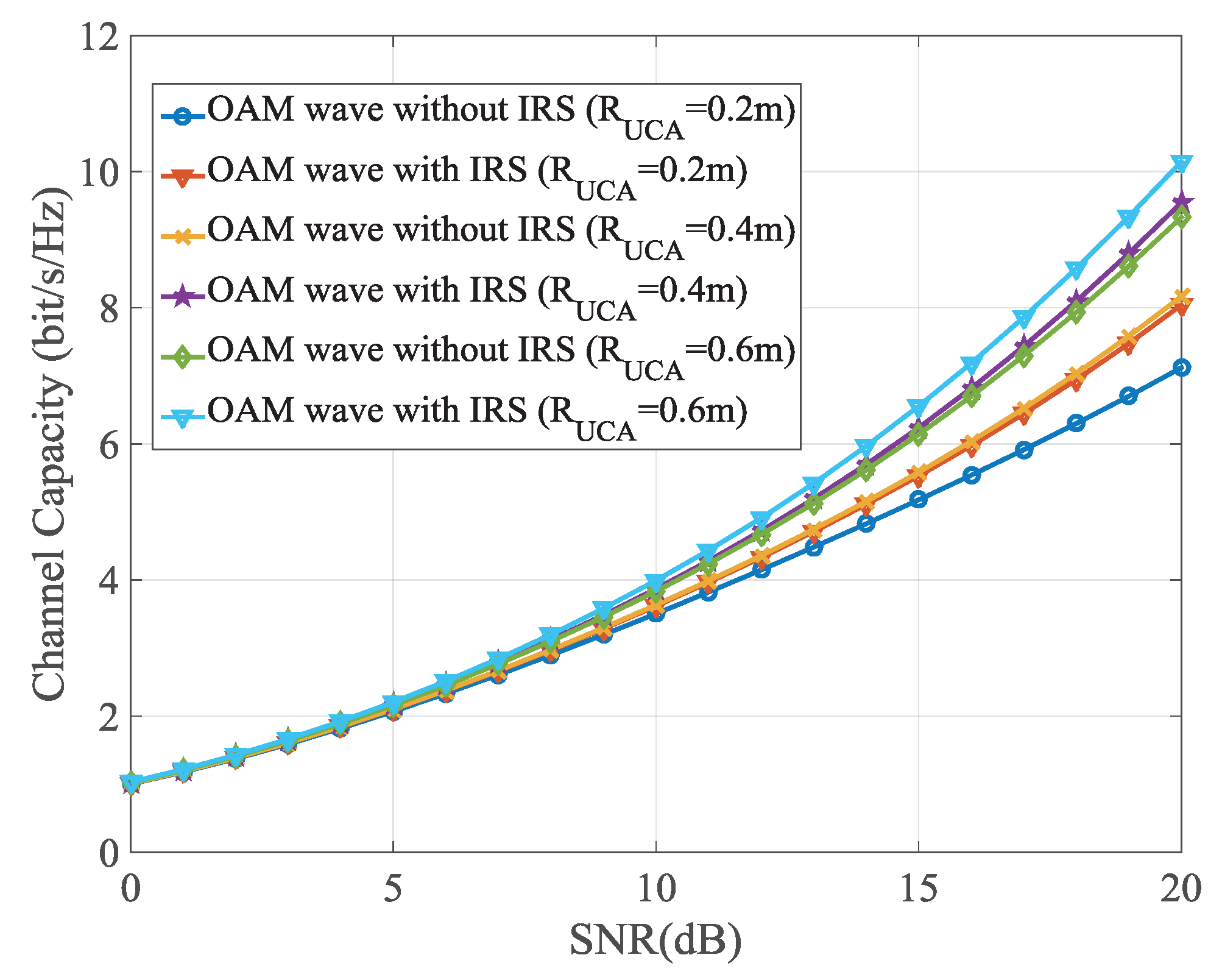
Figure 3.
The required receiving radius of the SBSC when the same received signal strength is achieved.
Figure 3.
The required receiving radius of the SBSC when the same received signal strength is achieved.
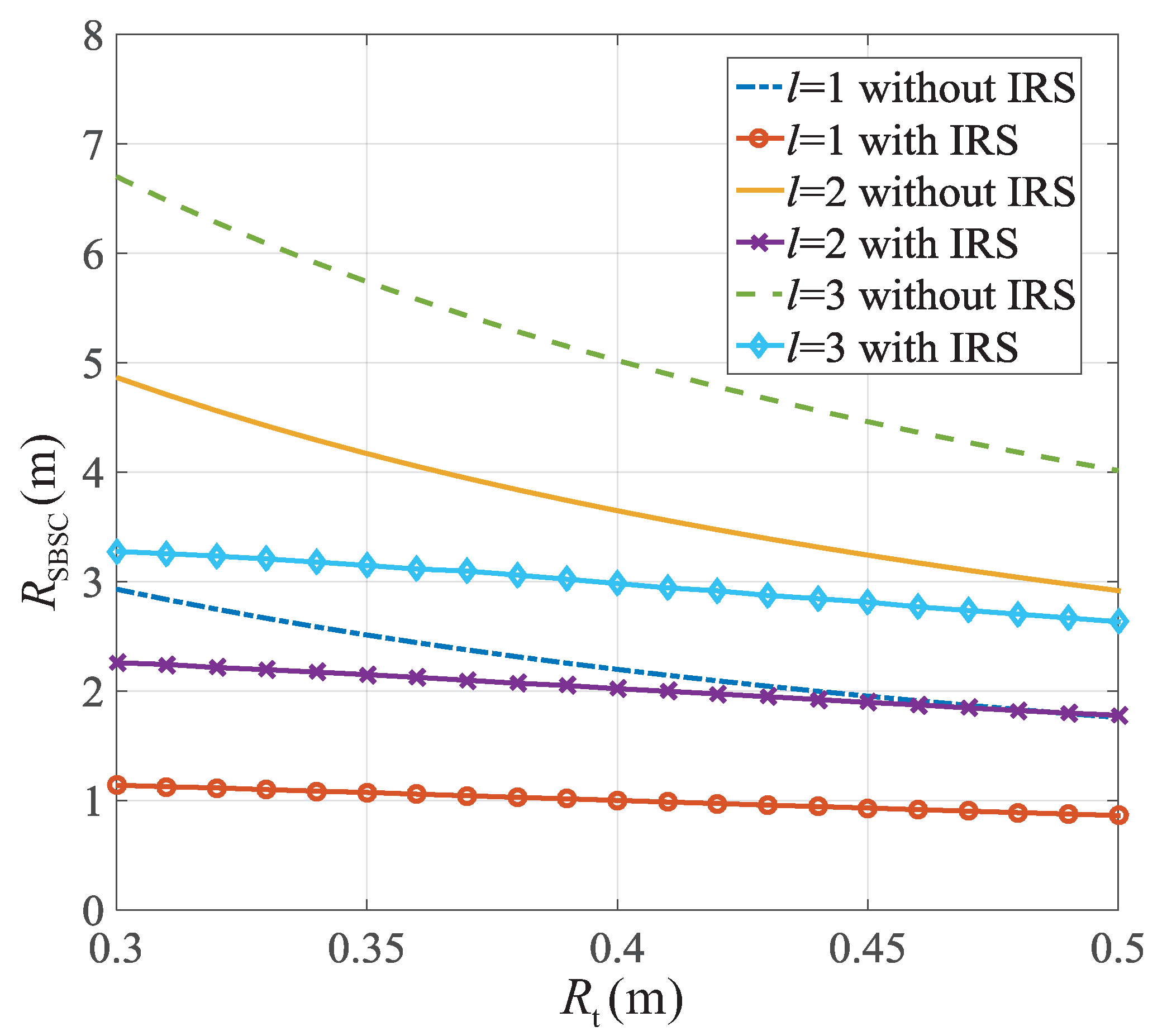
Figure 4.
Phase front of the electric field strength with and 16 when frequency is 10 GHz.
Disclaimer/Publisher’s Note: The statements, opinions and data contained in all publications are solely those of the individual author(s) and contributor(s) and not of MDPI and/or the editor(s). MDPI and/or the editor(s) disclaim responsibility for any injury to people or property resulting from any ideas, methods, instructions or products referred to in the content. |
© 2025 by the authors. Licensee MDPI, Basel, Switzerland. This article is an open access article distributed under the terms and conditions of the Creative Commons Attribution (CC BY) license (http://creativecommons.org/licenses/by/4.0/).
Copyright: This open access article is published under a Creative Commons CC BY 4.0 license, which permit the free download, distribution, and reuse, provided that the author and preprint are cited in any reuse.


