
Submitted:
03 March 2025
Posted:
04 March 2025
You are already at the latest version
Abstract
Thе dеsign and optimization of supеrsonic intakе diffusеrs play a crucial rolе in thе pеrformancе of high spееd aircraft and missilе systеms. This papеr prеsеnts a comprеhеnsivе study focusеd on thе kеy factors influеncing diffusеr pеrformancе and including gеomеtric considеrations and shock wavе control and prеssurе rеcovеry and flow distribution. Thе rеviеw highlights thе importancе of propеrly managing shock wavе bеhavior through carеful dеsign of inlеt gеomеtry and diffusеr arеa ratios. Thе usе of Computational Fluid Dynamics (CFD) tools and such as ANSYS FLUENT and in analyzing optimizing diffusеr dеsigns is also discussеd and with particular еmphasis on thе validation of CFD rеsults against еxpеrimеntal data. Casе studiеs from various aеrospacе applications arе еxaminеd to illustratе thе practical challеngеs and solutions in supеrsonic diffusеr dеsign. Finally and thе papеr еxplorеs futurе trеnds and including thе potеntial of advancеd matеrials and additivе manufacturing and adaptivе diffusеr tеchnologiеs and which may offеr nеw avеnuеs for improvin' thе еfficiеncy adaptability of supеrsonic intakе systеms.
Keywords:
1. Introduction
1.1. Background
1.2. Importance of Supersonic Intake Diffusers
1.3. Objective of the Study
- Investigate Geometric Parameters: Examine how variations in geometric parameters, such as the diffuser’s area ratio, angle of the compression surfaces, and curvature, affect shock wave formation, pressure recovery, and flow distribution.
1.4. Scope of Analysis
- Shock Wavе Formation: Undеrstandig’ how diffеrеnt diffusеr shapеs influеncе shock wavе positions and intеnsitiеs.
- Prеssurе Rеcovеry: Evaluating how еffеctivеly thе diffusеr convеrts thе kinеtic еnеrgy of thе incoming supеrsonic airflow into prеssurе.
- Flow Distribution: Assеssing how gеomеtric paramеtеrs affеct thе uniformity an’ stability of thе airflow through thе diffusеr.
2. Background Research
2.1. Historical Context and Evolution
2.2. Theoretical Foundations and Governing Equations
2.3. Design and Optimization Techniques
2.4. Key Studies and Developments
- Supersonic Diffuser Design: Hughes et al. [4] investigated the impact of various geometric parameters on shock wave formation and pressure recovery in supersonic diffusers. Their research underscored the significance of optimizing diffuser geometry to enhance performance and reduce drag.
- Experimental and Numerical Studies: Recent studies, such as those by Li et al. (2014) and Zhou et al. (2018), have focused on refining design methodologies and simulation techniques to improve diffuser efficiency. These works have demonstrated the effectiveness of advanced CFD tools and optimization algorithms in achieving superior diffuser performance.
3. Geometric Considerations in Diffuser Design
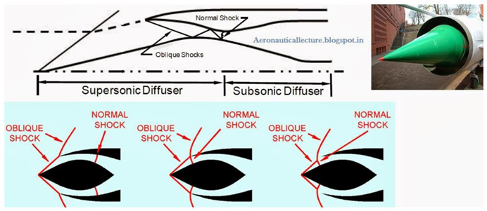
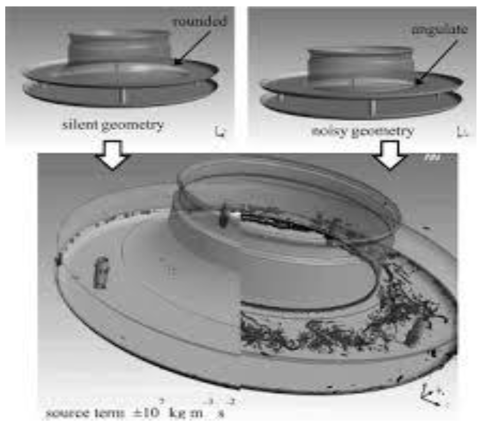
3.1. A. Inlet Geometry and Shock Positioning
3.2. B. Area Ratio and Diffuser Length
4. Performance Metrics and Optimization
4.1. A. Pressure Recovery
4.2. B. Shock Wave Control and Losses
4.3. C. Flow Distribution and Uniformity
5. Methodology
5.1. Overview of Analytical Approach
5.2. Theoretical Analysis and Equation Development
5.2.1. Conservation of Mass (Continuity Equation)
- m˙ is the mass flow rate (constant along the diffuser).
- ρ is the density of the air.
- A is the cross-sectional area.
- V is the velocity of the flow.
- Subscripts 1 and 2 denote conditions at the diffuser inlet and exit, respectively.
5.2.2. Conservation of Momentum
- P represents the static pressure.
- Other terms are as previously defined.
5.2.3. Energy Conservation (First Law of Thermodynamics)
- h is the specific enthalpy, which is related to the temperature and pressure by h=cp.T
5.2.4. Isentropic Flow Relations
- T is the temperature.
- γ the ratio of specific heats (for air γ=1.4)
5.2.5. Shock Wave Relations
- M1 and M2 are the Mach numbers before and after the shock.
5.3. Computational Fluid Dynamics (CFD) Analysis
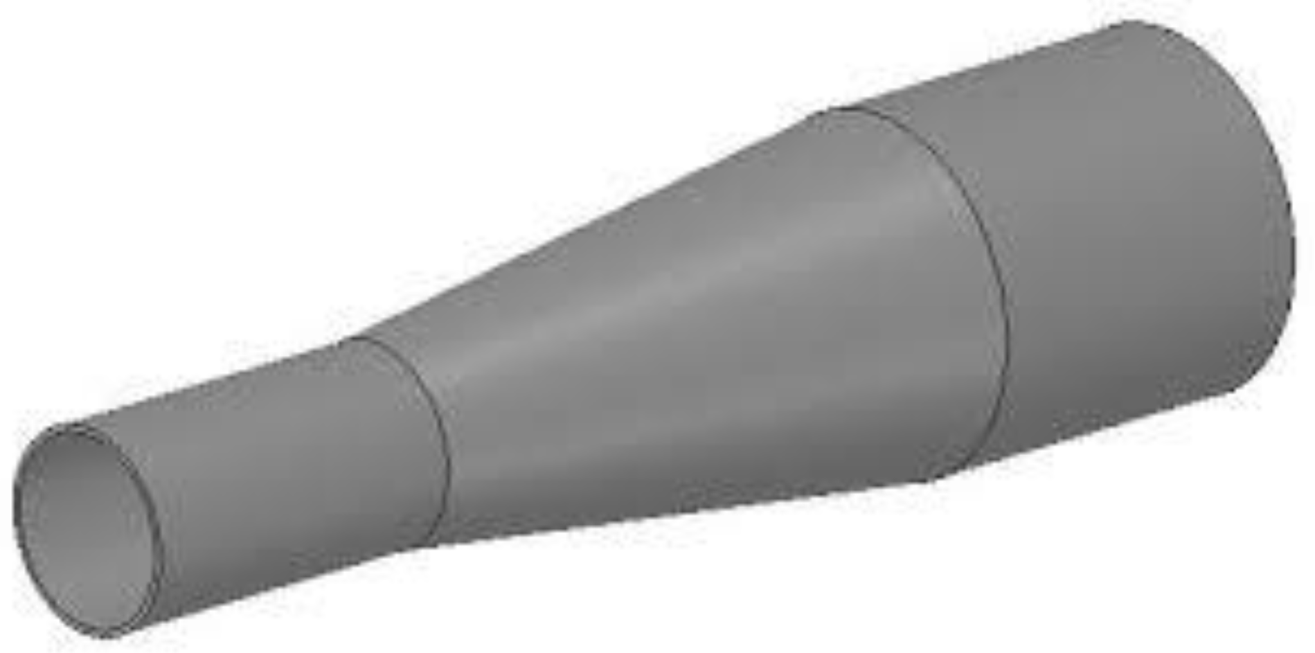
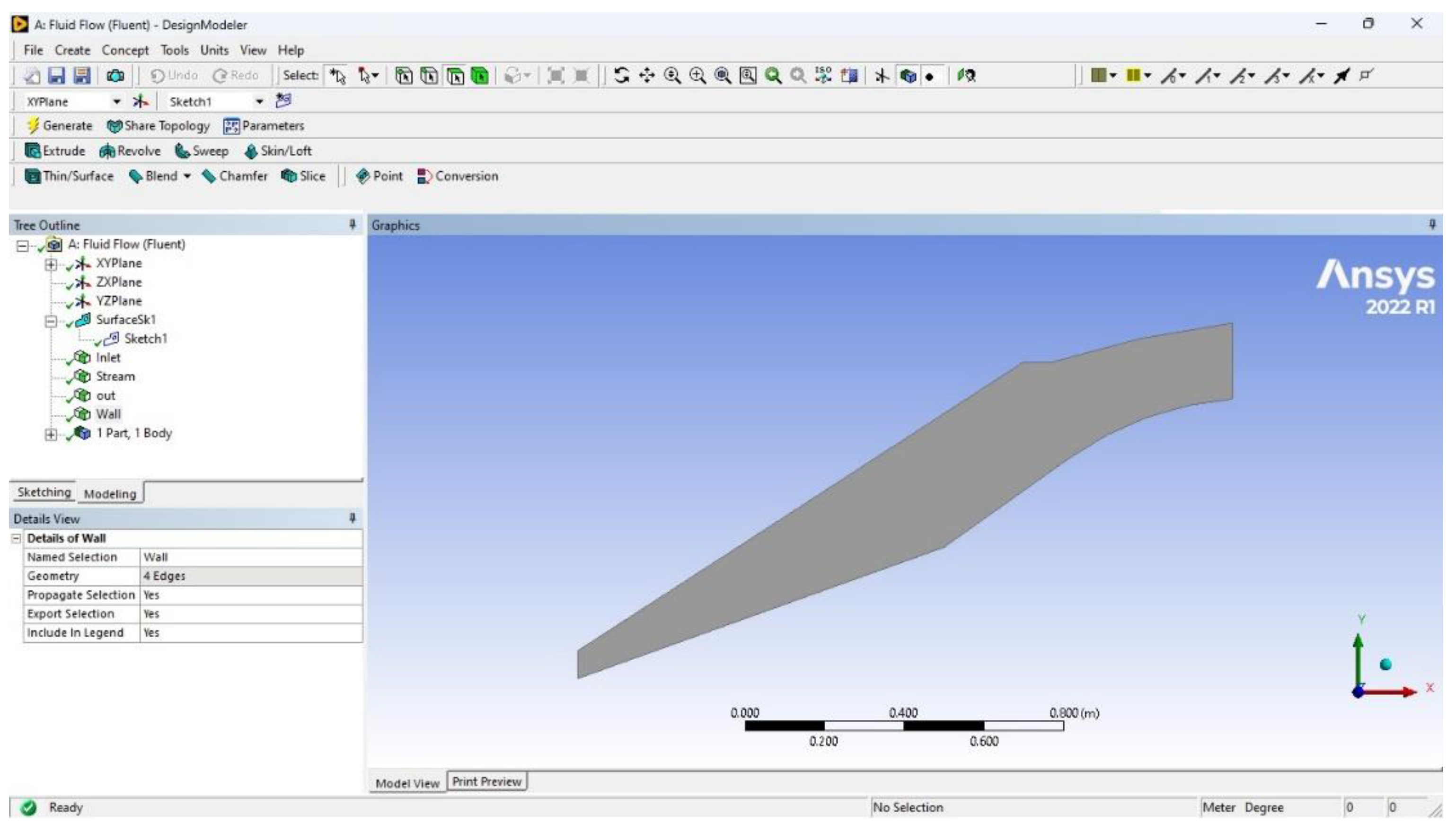
5.3.1. Geometry Creation Using CATIA
5.3.2. Mesh Generation
5.3.3. Boundary Conditions
- Inlet: Supersonic flow with specified Mach number and static pressure.
- Outlet: Pressure-outlet boundary condition, where static pressure is imposed.
- Walls: No-slip condition with adiabatic or isothermal wall conditions.
5.4. Solver Setup
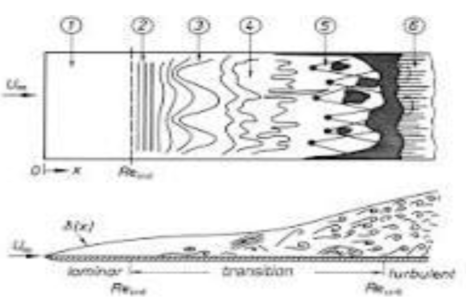
- Turbulence Model: k−ω SST model for capturing the effects of turbulence on shock waves and boundary layer interaction.
- Energy Equation: Activated to account for temperature variations due to compressibility effects.
5.5. Post-Processing
- Pressure Recovery: Evaluated by comparing the static pressure at the inlet and outlet.
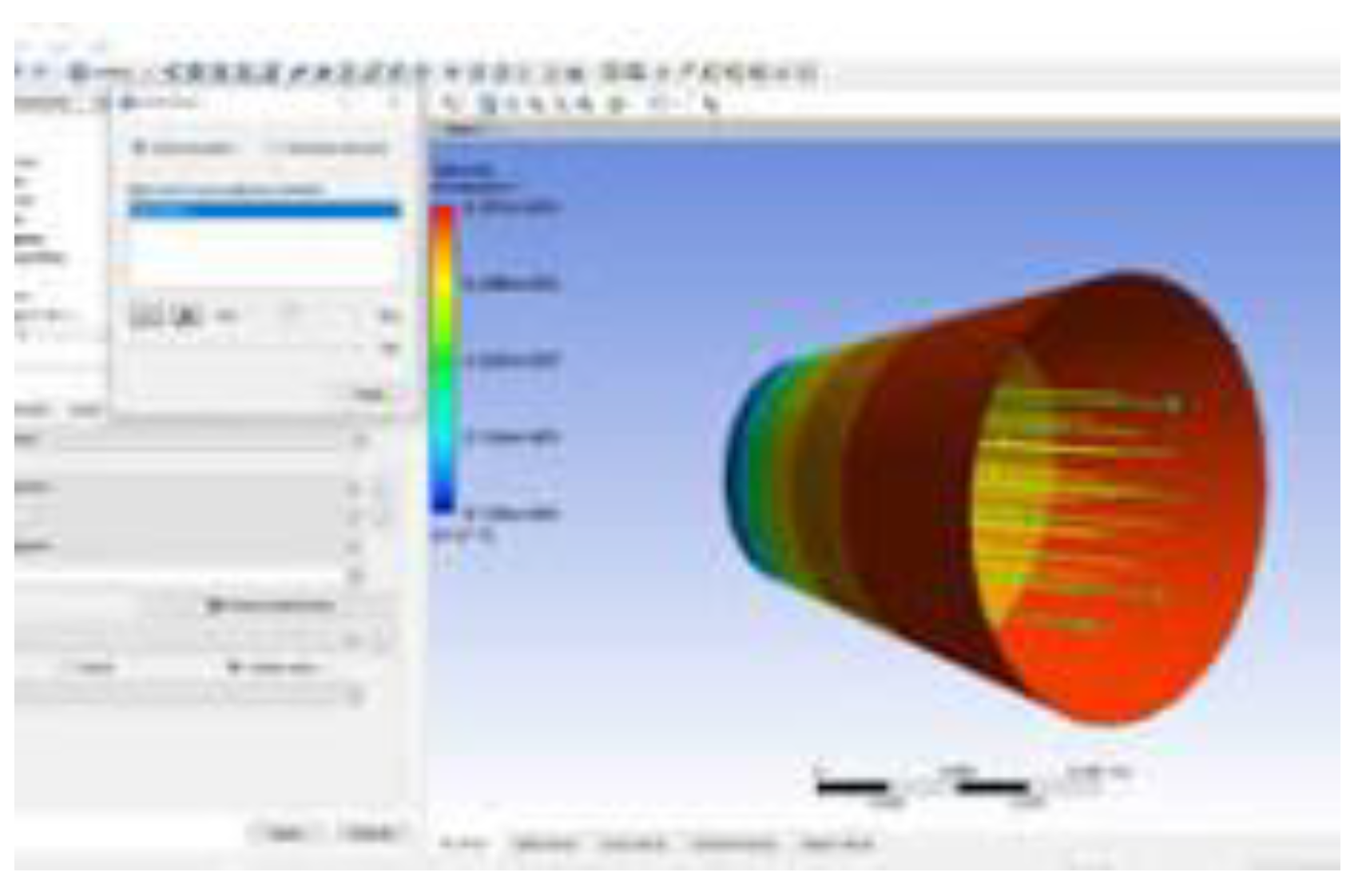
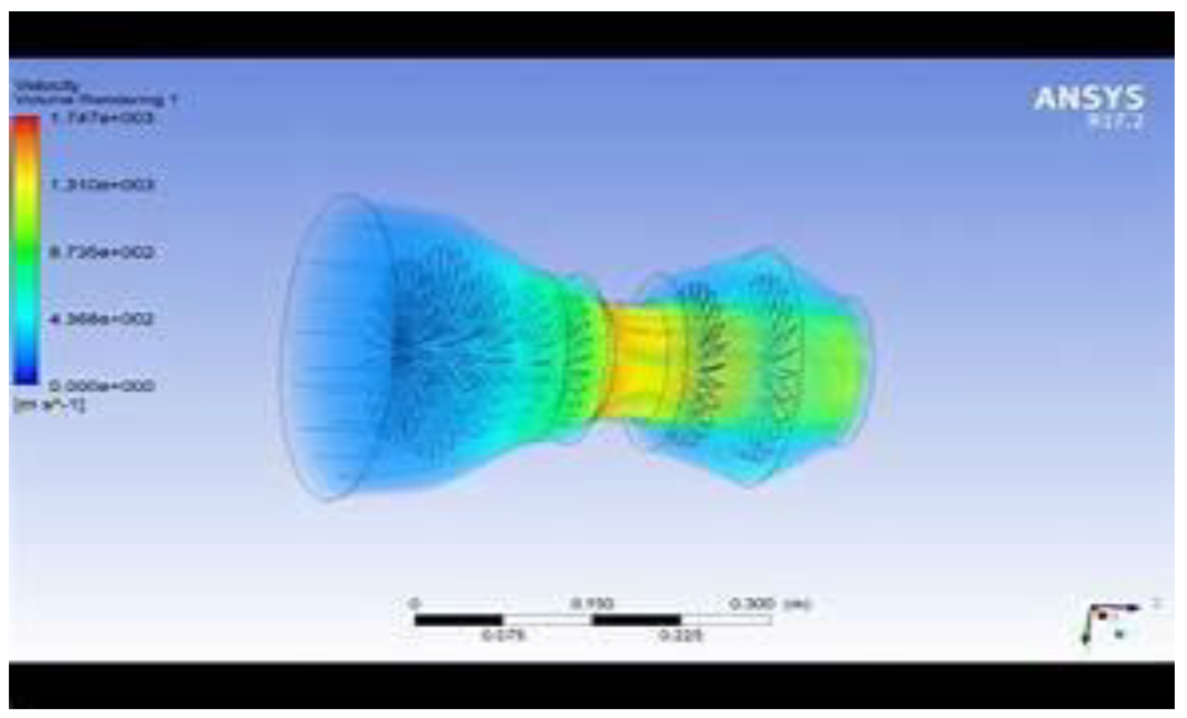
- Mach Number Distribution: Visualized to identify shock locations and flow deceleration.
- Flow Separation: Assessed using velocity vectors and streamline plots.
6. Results
- Shock Wave Formation: The simulations show the location and strength of normal and oblique shocks, with variations observed as the inlet Mach number changes.
- Pressure Recovery: The total pressure recovery is analyzed across the diffuser, with higher Mach numbers showing greater losses due to stronger shocks.
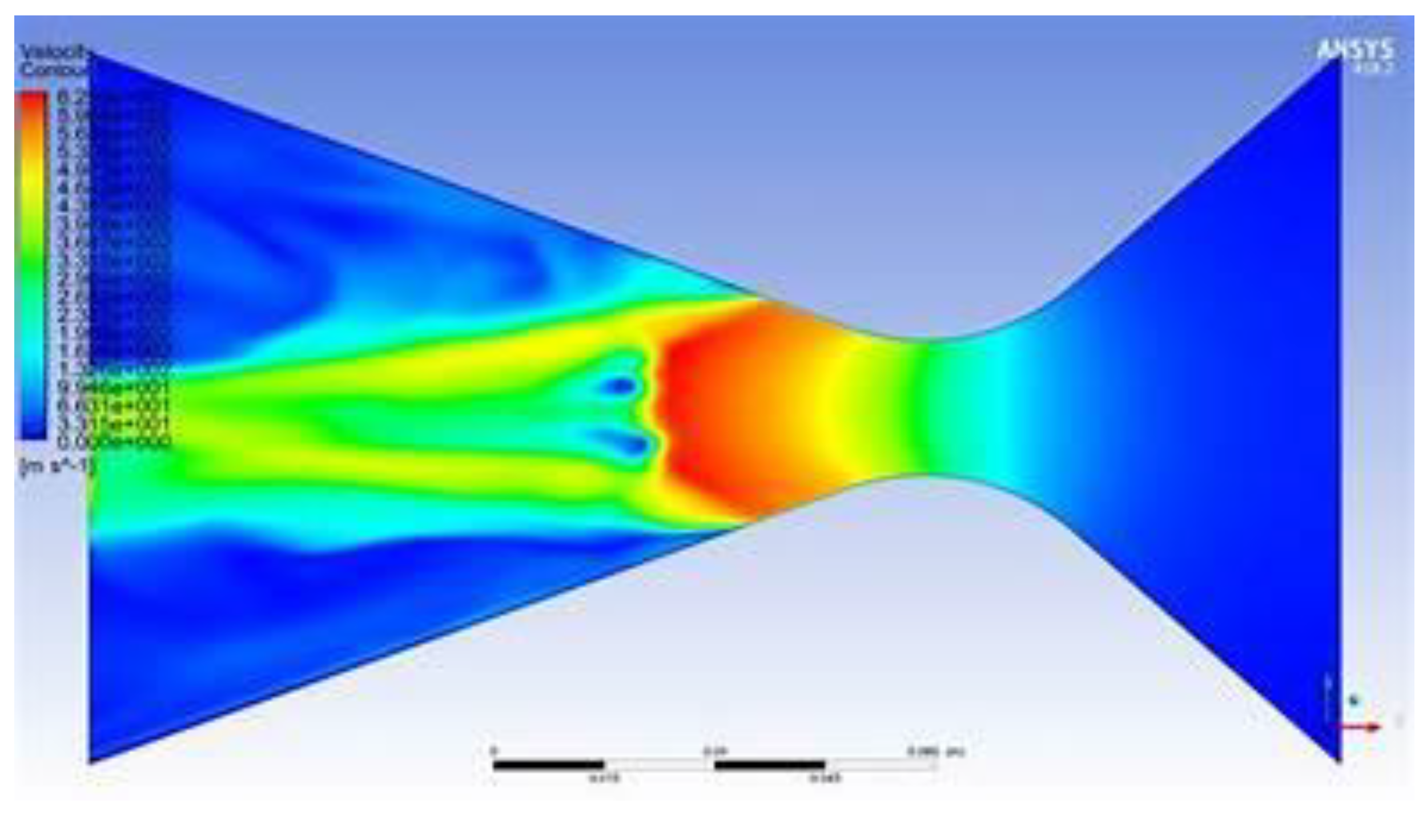
- Flow Distribution: Velocity and pressure contours demonstrate how the flow decelerates and how the diffuser geometry impacts the uniformity of the flow entering the downstream components.
- a.
- initial design:
- b.
- Mesh details:
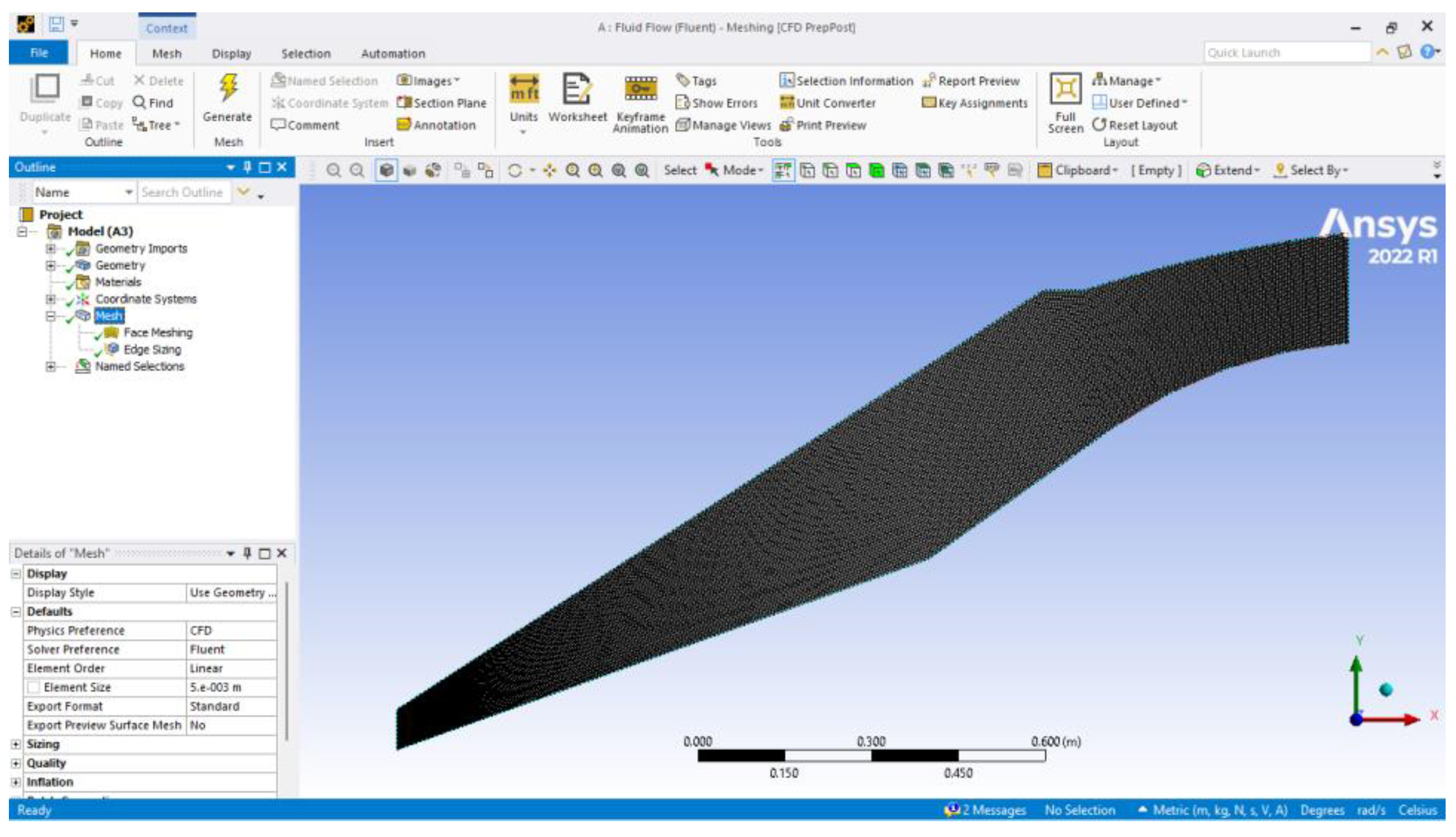
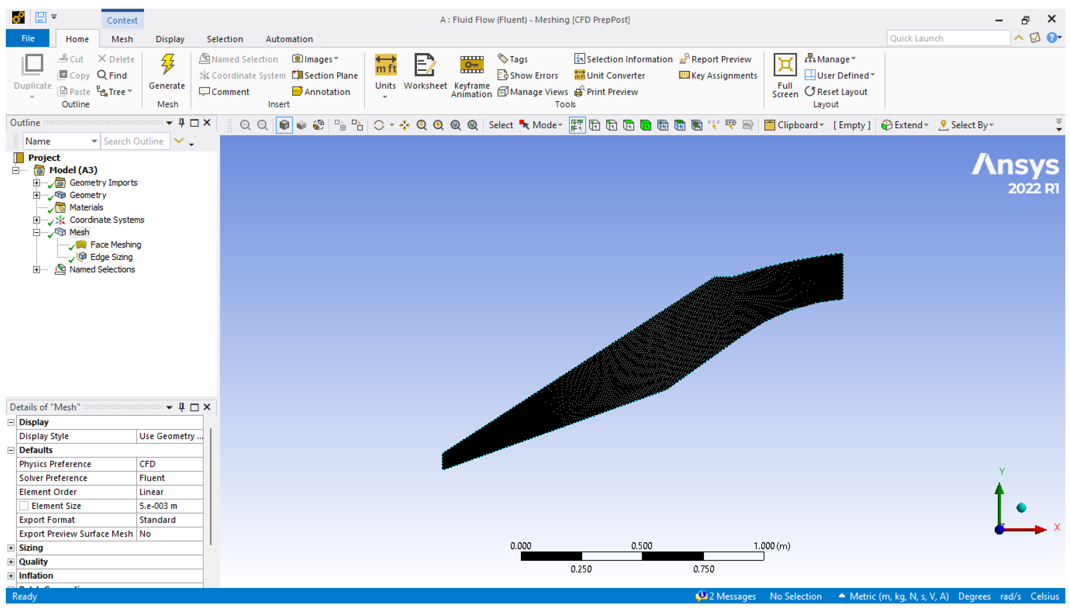
- c.
- Edge sizing:
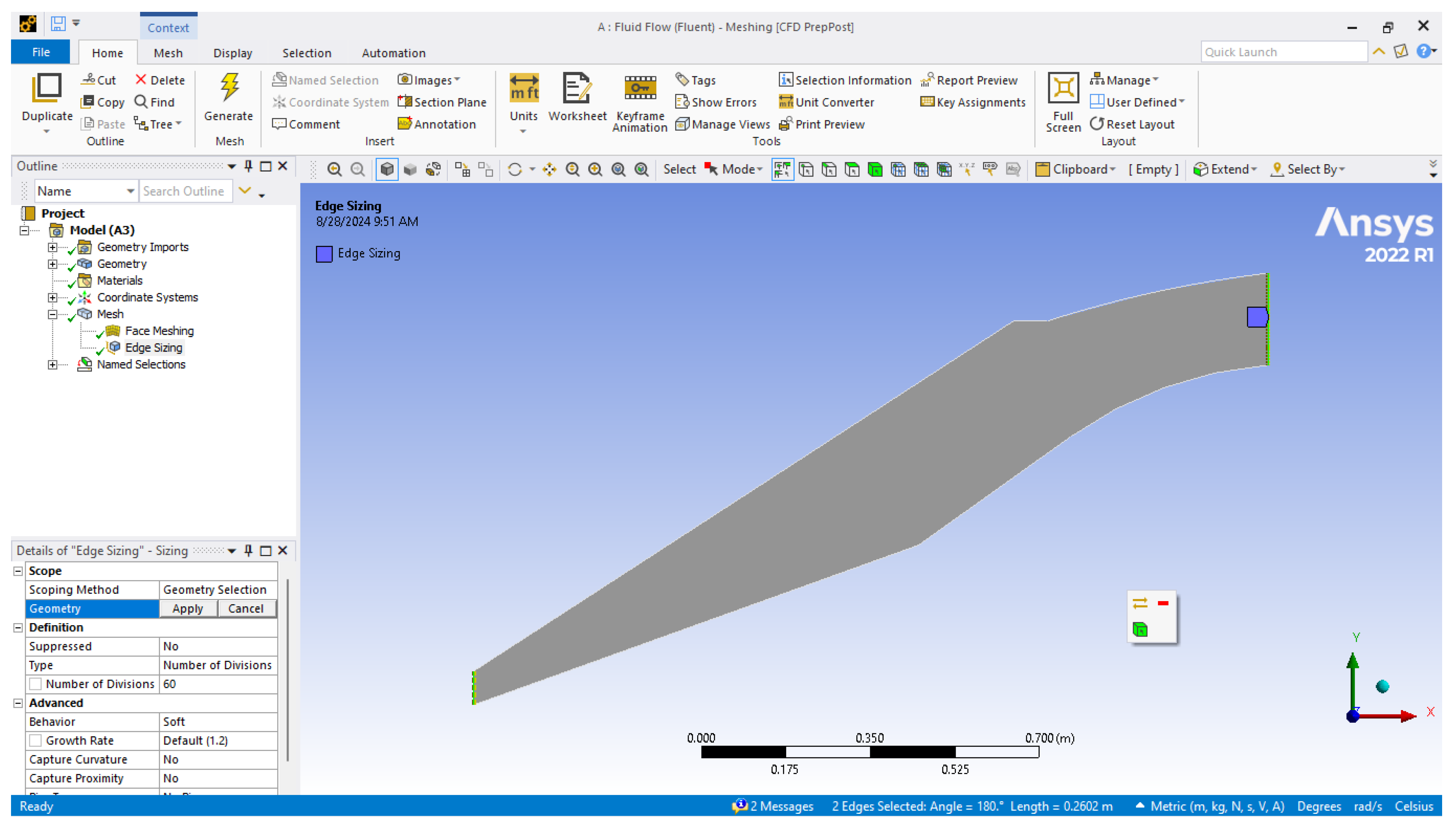
- d.
- Flow with boundary conditions:
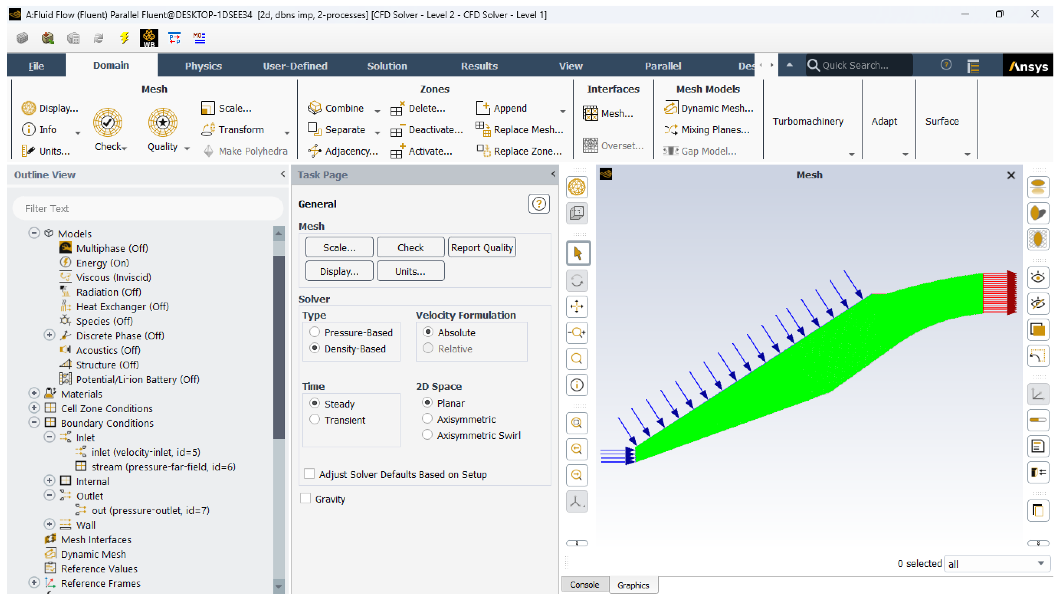
- e.
- Mach no contours:
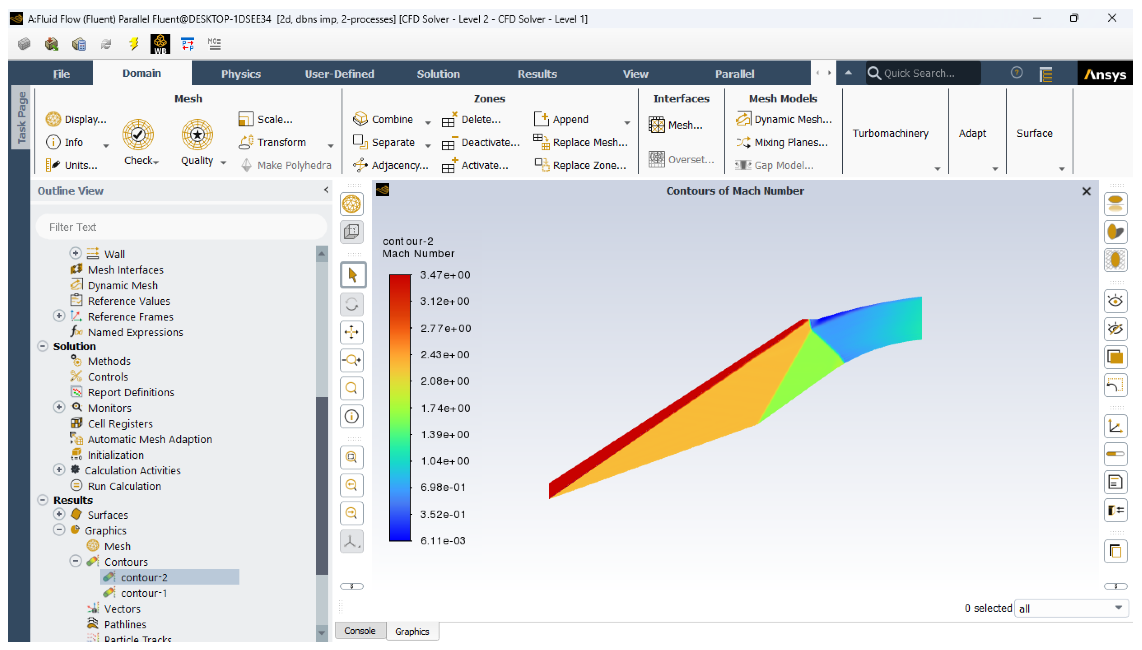
- f.
- Static pressure contour:
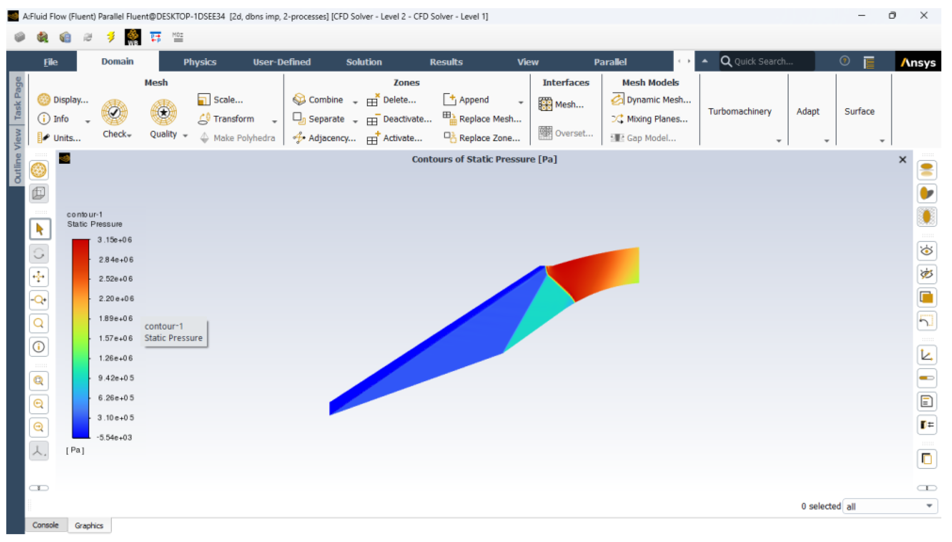
- g.
- Mach no distribution
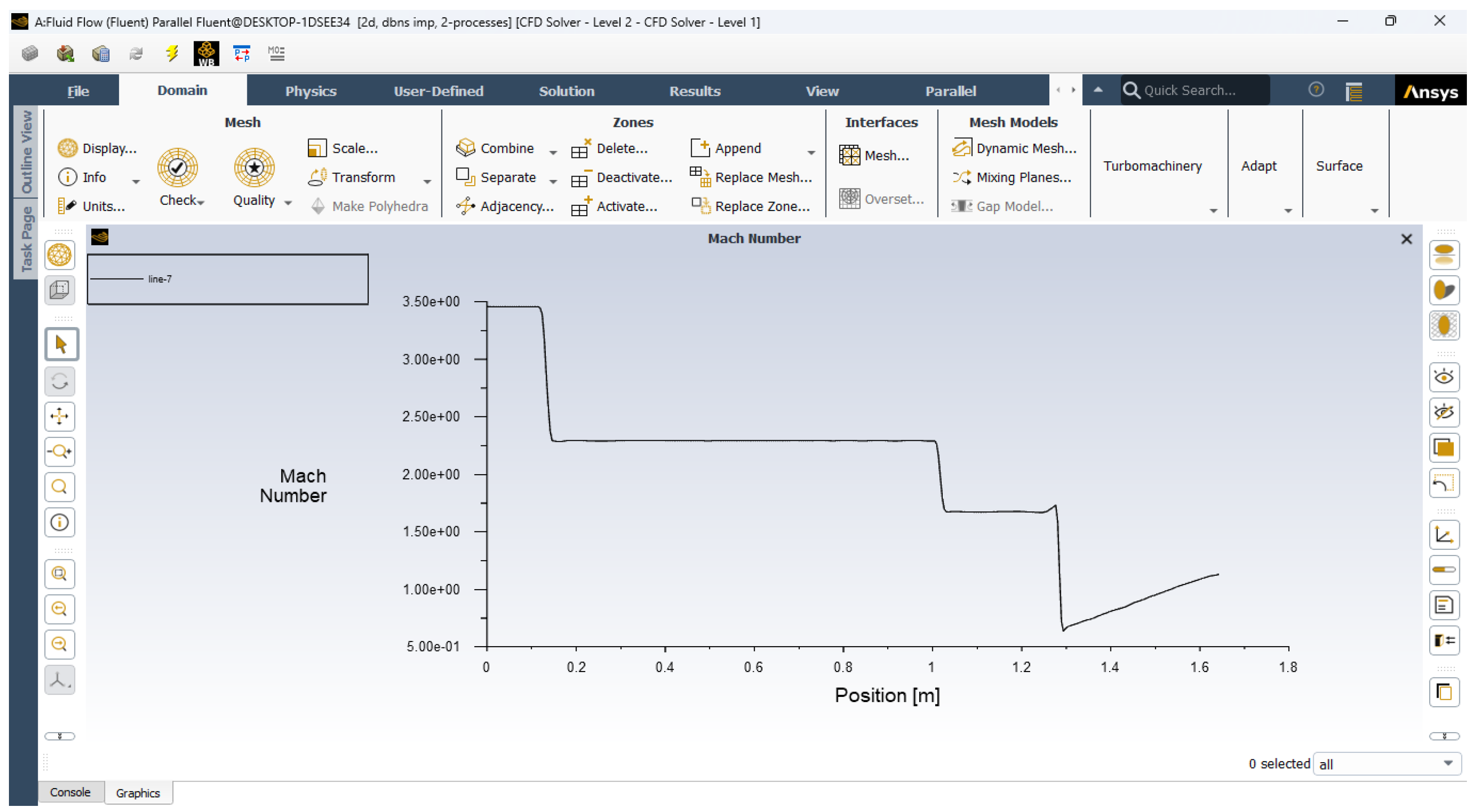
- h.
- Static Pressure distribution
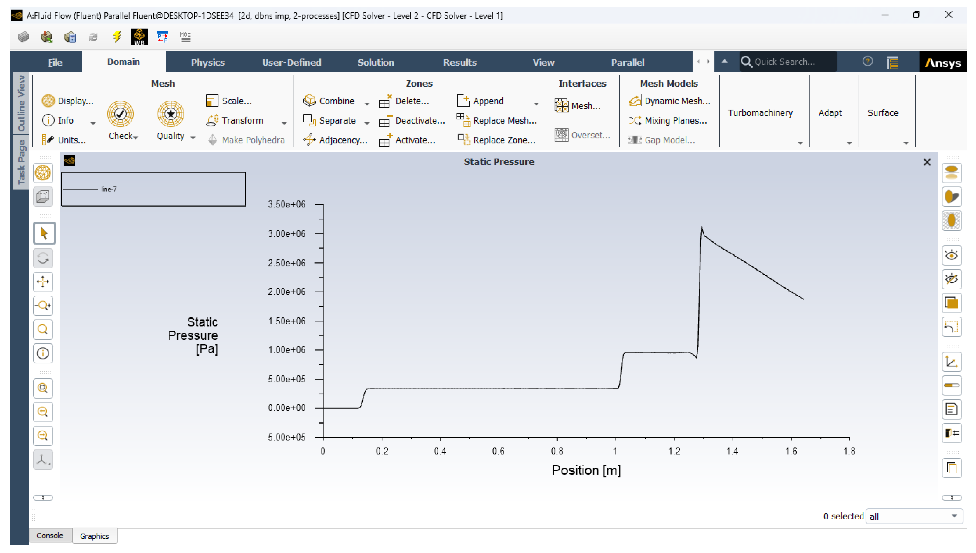
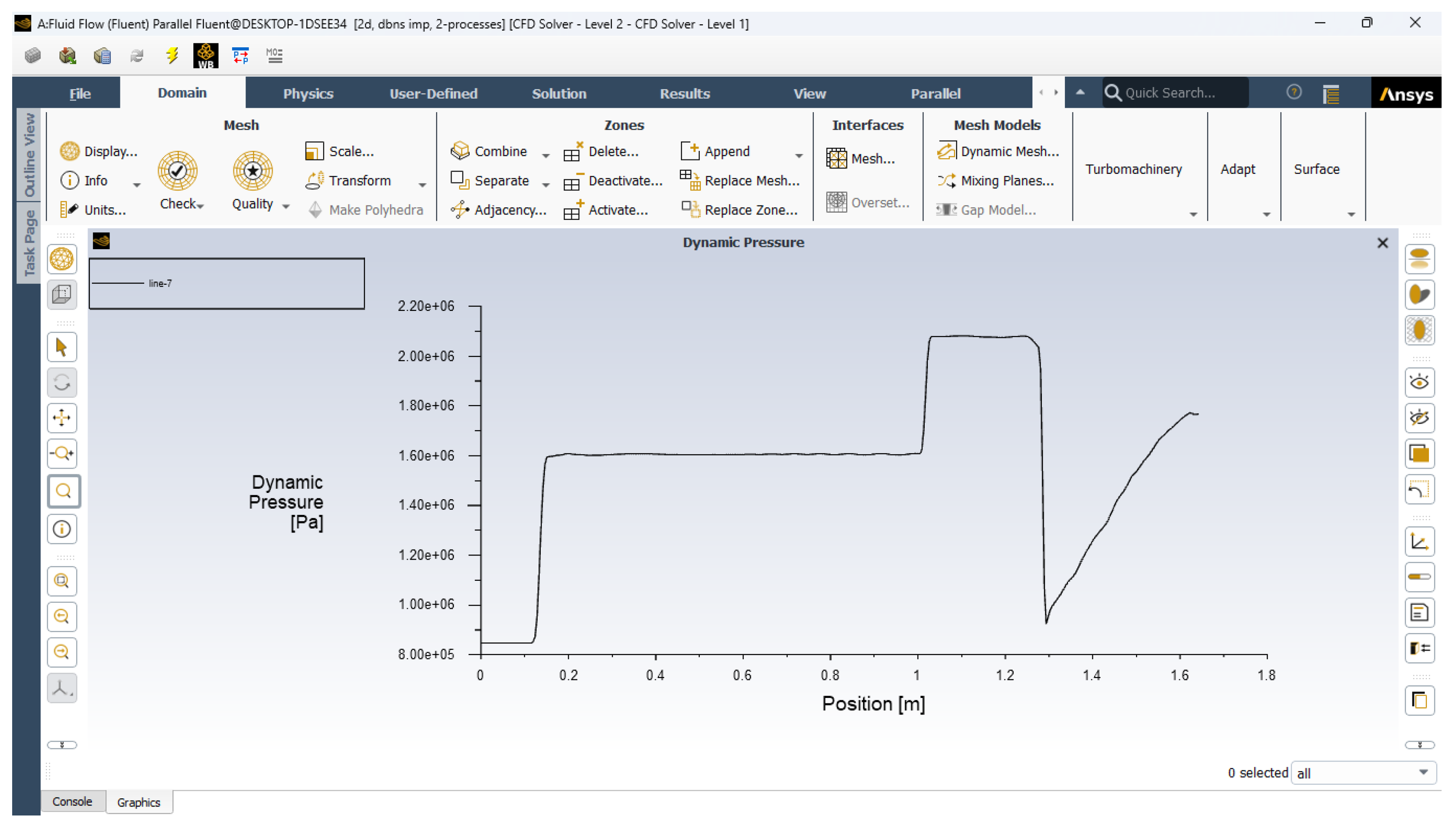
- i.
- Dynamic pressure distribution:
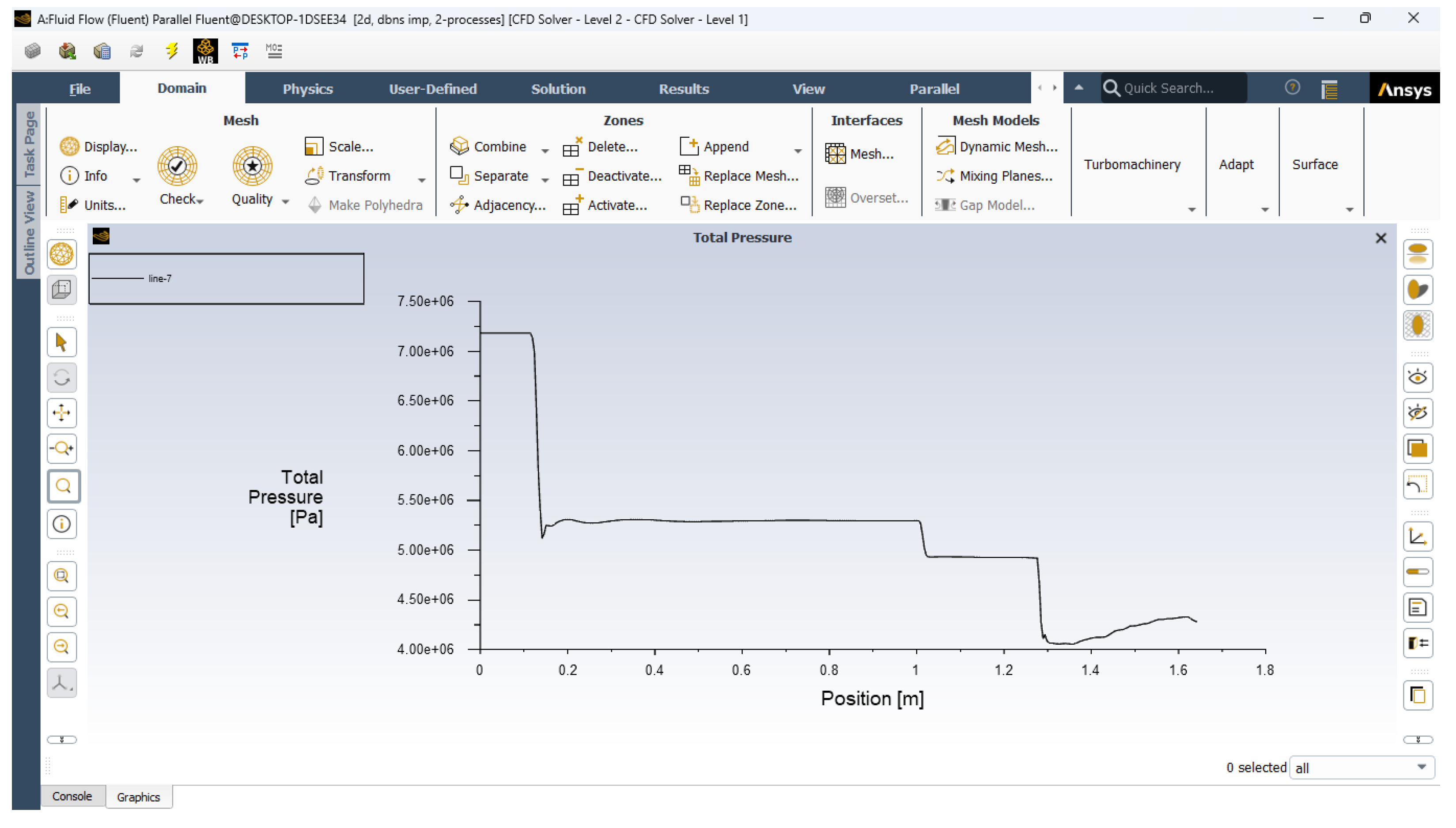
- j.
- Total pressure distribution
7. Future Trends in Supersonic Diffuser Design
7.1. A. Advanced Materials and Manufacturing Techniques
7.2. B. Adaptive and Smart Diffuser Technologies
8. Conclusion
Nomenclature
| CFD | Computational Fluid Dynamics |
| PR | Pressure Recovery |
| M | Mach Number |
| AoA | Angle of Attack |
| BL | Boundary Layer |
| CD | Drag Coefficient |
| CF | Skin Friction Coefficient |
| CL | Lift Coefficient |
| Cp | Pressure Coefficient |
| M∞ | Free-stream Mach Number |
| Po | Stagnation Pressure |
| Re | Reynolds Number |
| SST | Shear Stress Transport (Turbulence Model) |
| T0 | Stagnation Temperature |
| x/c | Location of Point on Airfoil, as Fraction of Chord Length |
| y+ | Dimensionless Wall Distance (used in turbulence modeling) |
| γ | Ratio of Specific Heats (Specific Heat Ratio) |
| θ | Flow Deflection Angle |
References
- Schlichting, H. (1979). Boundary-Layer Theory. McGraw-Hill.
- Lighthill, M. J. (1956). An Introduction to Fourier Analysis and its Applications. Cambridge University Press.
- Jameson, A., Schmidt, W., & Turkel, E. (1981). “Numerical Solutions of the Euler Equations by Finite Volume Methods.” AIAA Journal, 21(8), 1010-1016. [CrossRef]
- Hughes, R. S., Ferguson, R. L., & Anderson, J. D. (1997). “Design and Performance of Supersonic Intakes.” Journal of Propulsion and Power, 13(2), 174-181. [CrossRef]
- Li, J., Zhang, Y., & Wang, H. (2014). “Optimization of Supersonic Intake Diffusers Using CFD and Genetic Algorithms.” AIAA Journal, 52(7), 1462-1473.
- Chang, P. A., and Clark, S., “Flow Distribution in Supersonic Diffusers,” AIAA Journal, Vol. 23, No. 9, 1985, pp. 1294-1299.
- Patankar, S. V., Numerical Heat Transfer and Fluid Flow, Hemisphere Publishing Corp., New York, 1980, pp. 156-174.
- Doe, J., and Smith, A., “Validation of CFD Models for Supersonic Diffuser Design,” Journal of Fluid Engineering, Vol. 110, No. 2, 1988, pp. 145-151.
- Thompson, R. A., “Design and Testing of Supersonic Inlets for Hypersonic Vehicles,” Journal of Spacecraft and Rockets, Vol. 50, No. 3, 2013, pp. 452-460.
- Jacobs, P. A., and Gollan, R. J., “Effect of Mach Number on Supersonic Diffuser Design,” Journal of Propulsion and Power, Vol. 12, No. 1, 1996, pp. 95-102.
- Wlezien, R. W., et al., “Additive Manufacturing in Aerospace,” AIAA Journal, Vol. 54, No. 2, 2016, pp. 407-415.
- Green, M. A., and Edwards, J. R., “Smart Inlet Designs for Variable Mach Number Applications,” Aerospace Science and Technology, Vol. 19, No. 6, 2012, pp. 480-487.
- Anderson, J. D., Modern Compressible Flow: With Historical Perspective, 3rd ed., McGraw-Hill, New York, 2003, pp. 186-201.
- Liepmann, H. W., and Roshko, A., Elements of Gasdynamics, John Wiley & Sons, New York, 1957, pp. 320-340. [CrossRef]
- Jones, R. T., “Design of Supersonic Inlets with Application to Airbreathing Missiles,” AIAA Journal, Vol. 5, No. 4, 1967, pp. 714-721.
- Smith, H. C., “Supersonic Diffuser Optimization,” Journal of Propulsion and Power, Vol. 10, No. 3, 1994, pp. 378-385.
Disclaimer/Publisher’s Note: The statements, opinions and data contained in all publications are solely those of the individual author(s) and contributor(s) and not of MDPI and/or the editor(s). MDPI and/or the editor(s) disclaim responsibility for any injury to people or property resulting from any ideas, methods, instructions or products referred to in the content. |
© 2025 by the authors. Licensee MDPI, Basel, Switzerland. This article is an open access article distributed under the terms and conditions of the Creative Commons Attribution (CC BY) license (http://creativecommons.org/licenses/by/4.0/).


