
Submitted:
01 March 2025
Posted:
04 March 2025
You are already at the latest version
Abstract
Urban planning has become increasingly complex, necessitating the use of digitized data, large-scale city scans, and advanced tools for planning and development. Recent advancements in open-source 3D modeling software – Blender, have introduced powerful procedural editing tools like geometry nodes, alongside robust mesh and curve manipulation capabilities. These features position Blender as a viable and cost-effective alternative to proprietary solutions in urban planning workflows. This study identifies common requirements, tasks, and workflows associated with cityscape transformation and visualization, implementing them within Blender’s environment. Documented working examples are provided, including procedural editing, cloud painting, and mesh transformation operations, demonstrating Blender’s versatility. To evaluate its practicality and performance, we conducted a comparative analysis with Rhinoceros Grasshopper, a widely used tool in urban planning. Metrics such as computational efficiency, workflow adaptability, and user experience were analyzed across multiple scenarios involving point cloud processing, mesh editing, and visualization tasks. Finally, we suggest further potential improvements aided by Blender’s powerful scripting framework.
Keywords:
procedural modeling
; point cloud processing
; computational design
; open-source GIS
; parametric urban design
1. Introduction
The increasing accessibility of high-resolution point cloud datasets has significantly enhanced urban planning capabilities, providing planners with detailed spatial data for analysis and decision-making. Advances in data acquisition technologies, such as LiDAR and photogrammetry, have facilitated the creation of extensive urban point cloud datasets, many of which are publicly available for research and practical applications. Examples include city-scale LiDAR datasets such as Toronto-3D [1], which supports autonomous driving and urban mapping, and Paris-Lille-3D [2], designed for automatic segmentation and classification of urban infrastructure. Additional datasets, such as SemanticKITTI [3] and TUM-MLS-2016 [4], further contribute to the understanding of urban environments. National airborne LiDAR datasets, such as those from Slovenia [5,6] and the Netherlands [7], provide extensive coverage but at lower resolution and with a field of view limited to airborne acquisition.
These and similar datasets not only enable the development of machine learning algorithms for urban scene understanding but also facilitate the integration of point cloud data into urban planning workflows, promoting more data-driven and effective decision-making [8,9,10].
As demand for detailed urban modeling grows, the proliferation of such datasets is crucial for advancing research and real-world applications. Alongside this, there is an increasing need for advanced visualization and editing tools that support interactive modeling and dataset refinement. Existing point cloud processing and editing tools primarily only focus on basic operations, such as cropping, trimming, translation, rotation, scaling, and parameter adjustment. However, they lack direct editing capabilities akin to those available in common 3D modeling applications, which support various geometry representations (e.g., polygon meshes, Bézier curves, NURBS surfaces, metaballs, and constructive solid geometry). Consequently, users often convert point cloud representations into alternative geometries to enable more advanced editing, a process that introduces errors and loss of data and disrupts traceability to the original data.
To address this gap, we propose a non-destructive direct point cloud editing approach implemented within Blender, a widely used open-source 3D modeling application. Our contributions include:
- Efficient handling of large point cloud datasets – enabling the loading and visualization of extensive datasets with level-of-detail functionality.
- Non-destructive point cloud editing – implementing operations such as copying, conditional removal, brush-based erasing, painting, and flattening using Blender’s Geometry Nodes system.
- Advanced rendering support – utilization of various point attributes, such as color, position, classification, etc. in combination with different shaders to provide informative and appealing visualizations.
The rest of this paper is structured as follows: sec:related-work presents relevant prior work. sec:background discusses existing tools and approaches in 3D modeling for urban planning. Our proposed methods and implementations are detailed in sec:methods, followed by an evaluation of results in sec:results. We discuss our findings and limitations in sec:discussion, and conclude with a summary and future research directions in sec:conclusion.
2. Related Work
The convergence of procedural modeling, point cloud technologies, and urban planning has driven significant advancements in urban design and visualization. Recent methodologies emphasize bridging artistic and technical aspects to enhance planning workflows. [11] explores the automatic transformation of 2D sketches into detailed 3D cad models using a visual transformer model, streamlining urban design for architects and planners. Similarly, [12] advocate for integrating scientific data with artistic representation based on an educational experiment that merges art and science to deepen landscape architecture students’ comprehension of available scientific data, enriching the discourse on landscape visualization. [13] highlight point clouds as a critical link between design and planning, demonstrating their role in generating accurate urban representations. These studies collectively underscore the growing reliance on advanced modeling techniques to improve visualization, analysis, and sustainability in urban planning.
2.1. Procedural Methods in Urban Modeling
Procedural modeling has emerged as a powerful tool for urban design, addressing the inefficiencies of traditional methods. [14] showcase a procedural framework using CityEngine1 to generate 3D urban models from gis datasets, exemplifying efficient large-scale modeling. [15] extend this approach by integrating environmental factors, such as flood sensitivity, demonstrating how procedural techniques enhance urban resilience. Additionally, [16] emphasize the automatic procedural generation of complex urban geometries, highlighting the need for scalable modeling tools.
The role of open-source tools in procedural modeling is increasingly recognized. [17] advocate for open-source software to democratize access to urban design capabilities, while [18] emphasize their potential for promoting sustainable urban development. In the Blender ecosystem, Ladybug tools2 provide environmental analysis functionalities, fostering sustainable design. [19] further integrate URBANopt3 and Dragonfly4 for energy-efficient modeling, streamlining workflows for practitioners.
Naboni et al. [20] introduce a digital workflow for quantifying regenerative urban design, demonstrating how procedural modeling supports sustainability by optimizing urban landscapes for resilience and adaptability. These studies collectively underscore procedural modeling’s transformative impact on urban visualization and planning.
2.2. Point Cloud Modeling
Advancements in LiDAR and mobile laser scanning have expanded point cloud applications in urban planning. [21] provide a comprehensive overview of mobile laser scanning for generating high-resolution 3D point clouds, facilitating detailed urban modeling and decision-making. [22] focus on airborne laser scanning for urban tree extraction, showcasing point clouds’ utility in managing green spaces. [23] further integrate artificial intelligence with point cloud data to improve urban forestry management, demonstrating its versatility in ecological planning.
2.3. Point Clouds in Urban Planning
The integration of point clouds into urban planning enhances data-driven decision-making. [24] highlight their potential in sustainable governance, including energy and resource management. [25] explore point-cloud-driven virtual reality systems for urban design, emphasizing stakeholder engagement through real-time interactive visualization. [26] utilize point cloud data to define urban development boundaries, supporting sustainable spatial planning.
Additionally, [27] review the role of LiDAR in 3D urban modeling, underscoring its precision for applications such as infrastructure management and environmental monitoring. [28] focus on urban forest monitoring, illustrating how point clouds contribute to vegetation health assessment and green space planning. These studies highlight the growing significance of point clouds in creating more sustainable, resilient urban environments.
Despite the advancements in procedural modeling and point cloud integration for urban planning, existing approaches face several limitations. Many procedural tools, such as CityEngine, prioritize large-scale city generation but lack direct editing capabilities for high-resolution point cloud datasets, restricting their adaptability in detailed urban modeling. Similarly, while point clouds serve as a crucial link between design and planning, current software solutions often focus on visualization and analysis rather than interactive editing and transformation, forcing users to convert point clouds into alternative geometric representations, leading to data loss and reduced accuracy. Proprietary solutions offer powerful but rigid workflows that limit customization and accessibility, while open-source tools, though promising, remain fragmented and underutilized in procedural urban design. Addressing these gaps, our approach leverages Blender’s procedural capabilities to introduce non-destructive point cloud editing, enabling interactive manipulation, enhanced rendering, and seamless workflow integration for urban planning tasks. By combining efficiency, flexibility, and accessibility, our work extends existing methodologies and provides an open-source alternative that supports both large-scale procedural urban modeling and detailed point cloud transformations.
3. Background
Several solutions exist for urban planning that support large point clouds with varying degrees of interactivity. Some software provides only basic visualization and cloud-level transformations, such as translation, rotation, and scaling, while others offer more advanced tools for point-level operations and fine-grained control over point cloud representations.
- Rhinoceros 3D and Grasshopper
Rhinoceros5 is a commercial cad software widely used in industrial design, architecture, and engineering, with growing adoption in urban planning. It supports 3D modeling with curves, surfaces, solids, and mesh geometry, and as of version 8.0, it includes native support for point clouds. Its extension, Grasshopper6, provides a node-based interface for generating geometry, applying algorithms, and performing various operations on objects within Rhinoceros.
In previous versions, point cloud editing required external add-ons for Grasshopper. One notable extension is Volvox7, which supports loading point clouds in ASTM E57 and XYZ formats. It allows basic point selection, deletion, and merging of multiple point clouds. Another tool, Veesus8, uses proprietary point cloud formats and primarily focuses on visualization and mesh generation. It includes a clash detection feature, which helps analyze collisions between meshes and point clouds for better alignment and topology adjustments.
With the release of Rhinoceros 8, point clouds can now be imported natively and fully integrated with Grasshopper. However, one drawback of Grasshopper is its operational model, where each command creates a copy of the geometry, making editing of large point clouds computationally and memory-intensive.
Due to its extensive point cloud functionalities and widespread community adoption, we selected Rhinoceros with Grasshopper as the primary benchmark for comparison in our study.
- Autodesk Software
Autodesk provides several commercial solutions for point cloud manipulation, including Revit9, AutoCAD10, and ReCap PRO11. Autodesk ReCap PRO specializes in 3D scanning and point cloud creation, producing project files compatible with Revit for further processing. It also supports external point cloud loading but is primarily designed for visualization rather than direct editing. Most Autodesk tools treat point clouds as static references for tasks like surface modeling and measurement rather than providing full transformation, reduction, or manipulation capabilities.
- Pix4D
Pix4D12 is a commercial software primarily focused on photogrammetry and point cloud analysis. It provides noise removal, basic point selection and deletion, and classification based on distance, elevation, and other parameters. Additionally, it includes tools for volume measurement, contour visualization, point cloud vectorization, and mesh generation.
- ArcGIS
We include ESRI ESRI ArcGIS13, a widely used gis software, which offers georeferencing and point classification using additional geospatial datasets. While it does not support direct point cloud editing, it allows manual selection and classification of points and semi-automatic classification based on other loaded geographical data.
- DJI Modify
DJI Modify14 is a toolset designed for area surveying and 3D modeling, integrating with DJI’s drone-based mapping solutions. It provides noise removal, point flattening, and hole-filling functionalities, allowing users to select point cloud regions and convert them into mesh geometry.
- Tcp Point Cloud Editor
Tcp Point Cloud Editor15 is an architectural planning tool that enables basic point cloud editing, including point deletion, density-based coloring, elevation-based classification, and visualization of individual cloud slices. It also supports mesh conversion, volume computation, and drawing over point clouds. A key feature is its integration with slam visualization, which enhances real-time point cloud analysis.
- Vega
Vega16 is an AutoCAD extension designed for point cloud visualization and technical drawing. It supports cloud slicing, contour line generation, manual and automatic triangulated irregular network creation, and 2D texture projection onto point clouds.
- 3D Survey
3D Survey17 provides an intuitive interface for a broad range of point cloud processing tasks. Features include point classification, selection, transformation, and removal, as well as terrain profile generation, resampling, multi-cloud registration, and orthophoto creation. One notable feature is the X-Ray view, where points are projected onto a plane with variable intensity, producing semi-transparent structural outlines of the scanned environment.
- CloudCompare
CloudCompare18 is the only open-source software among the tools reviewed. It is specifically designed for point cloud processing, providing functionalities such as point extraction, segmentation, transformation, classification, and format conversion. Its comprehensive toolset makes it a valuable resource for both research and practical applications in urban planning.
Most of the tools mentioned above, with the exception of Rhinoceros, offer limited point cloud editing capabilities and are primarily designed for specific, specialized workflows. As a result, their adaptability to diverse applications, such as urban planning, remains constrained, making them less suitable for flexible, general-purpose point cloud manipulation and transformation.
4. Methods
Our workflow for point cloud manipulation, as presented in Figure 1, consists of three stages: (1) preprocessing and import of the point cloud, (2) point cloud manipulation through node trees, and (3) rendering of resulting point cloud geometry.
4.1. Preprocessing
At the time of writing, both Blender and Rhinoceros provide limited native support for importing point cloud data. While both applications can handle PLY files, Rhinoceros offers broader format compatibility, including ASTM E57 and a few others.
Since LiDAR point clouds are commonly stored in the LAS format, preprocessing is necessary to convert these files into a format suitable for Blender or Rhinoceros. To achieve this, we utilized the open-source point cloud processing software CloudCompare to convert LAS files to ASTM E57 for Rhinoceros and PLY for Blender.
One common challenge with LiDAR-acquired point clouds is that their coordinates are often located far from the world origin, which can lead to precision issues in 3D modeling software. To mitigate this, we used CloudCompare to recenter the point cloud before importing it into either application.
Blender organizes scene data into objects, which can contain different types of geometry, such as meshes, curves, and surfaces. When imported into Blender, a point cloud is represented as an object consisting of unconnected vertices, which cannot be rendered directly and appear in the 3D Viewport as simple, unshaded circles. However, using Geometry Nodes, these vertices can be converted into points represented by geometry instances, allowing them to be shaded and rendered effectively.
4.1.1. lod and Classifications
The current architecture of Blender imposes a fixed point buffer limit of approximately 4.2 GB per object, restricting the number of points per object that can be displayed in the 3D Viewport. Since our work involves large point clouds containing millions of points, we introduce LOD to optimize point cloud rendering and interaction across different hardware configurations. To address both memory limitations and performance concerns, we implemented LoDs as separate objects, each containing a subset of points to ensure the buffer limit is not exceeded. These objects can be hidden or revealed dynamically, allowing users to switch between lower- and higher-detail representations as needed.
In LiDAR datasets, points can be classified into 256 categories, representing features such as ground, buildings, railways, roads, and vegetation. To enable toggling the visibility of points based on classification, we considered two approaches:
- Storing points of different classes in separate objects – This approach leverages Blender’s standard object visibility mechanisms, allowing classification-based filtering across different LoDs via scripting.
- Storing the class ID as a point attribute – Here, classification visibility is controlled directly through Geometry Nodes, enabling efficient filtering and seamless color-based rendering based on class attributes.
The first approach provides better display performance and simplifies classification management, as visibility toggling can be handled efficiently at the object level. Additionally, the object creation process is highly optimized, taking only a few seconds in our implementation.
However, we ultimately adopted the second approach, as it integrates more seamlessly with Geometry Nodes, allowing each point to retain its classification information. This proved particularly useful in the shading stage, where points can be dynamically assigned colors based on their classes. Despite these advantages, this approach resulted in longer processing times due to the overhead of constructing the node tree for classification-based filtering. Specifically, since Geometry Nodes lack native support for array-based toggling, 256 boolean inputs and 512 boolean math nodes had to be generated to manage classification visibility. While this workaround is computationally expensive, it was necessary given current limitations in Blender’s node-based system. Future updates may introduce native support for array-based operations, as this has been a recurring feature request from the Blender community.
4.1.2. Normal Computation
Computing normals for point clouds requires external tools such as CloudCompare or custom script implementations. In the case of Blender, we developed a custom PCA-based normal computation inspired by [29,30]. Our approach involves preprocessing PLY files externally, where normals are computed and updated before being reloaded into Blender. This ensures that point clouds maintain accurate normal information for subsequent shading and rendering operations.
4.1.3. Viewport Display
To ensure proper visualization of point clouds in Blender’s 3D Viewport, both materials and an initial Geometry Nodes configuration must be set up. Each point cloud object requires a Geometry Nodes modifier, which converts unconnected vertices into point instances for correct display. Additionally, a material must be applied to enable accurate point coloration.
For optimal real-time visualization, the Material Preview shading mode provides the best balance between performance and visual clarity. When using the EEVEE rendering engine, disabling shadow calculations can further improve viewport performance, reducing computational overhead and ensuring smoother interaction with large point clouds.
4.2. Editing
We evaluated Blender’s capabilities by testing a selection of operations that are commonly used in urban planning and similar applications, as identified in published workflows. All operations were implemented using Geometry Nodes, with certain parameters dynamically controlled via auxiliary objects and mesh primitives to facilitate real-time transformations in the 3D Viewport.
For instance, to define a specific region of interest, we used a Cube primitive, adjusting its position and scale to encompass the desired set of points. Within the node tree, we identified points contained within the Cube using the Object Info and Raycast nodes. As the Cube was further manipulated, the Geometry Nodes computation updated dynamically, ensuring real-time responsiveness.
When constructing operations within Blender’s Geometry Nodes, it is important to note that point clouds are initially represented as unconnected vertices. Therefore, at some stage, the geometry must be explicitly converted into renderable points using the Mesh to Points node. This conversion can be introduced at any point in the node tree; however, we have not extensively analyzed the performance implications of different placements within our tested operations.
Additionally, we observed that the Set Material node should preferably be applied last in the node tree, as some geometry-altering nodes remove previously assigned material definitions. This workflow is visually outlined in Figure 2.
- Point Copying
Points can be duplicated and transformed based on a specified condition, such as location, color, or classification. This functionality is particularly useful for rapid prototyping and early-stage design, where existing structures within the point cloud can be reused and repositioned in different areas.
In Blender, point duplication can be achieved by encapsulating a region of interest within a primitive, such as a Cube. The primitive’s geometry can be accessed via the Object Info node, while the Raycast node is used to determine which points fall within the Cube’s boundaries. Once the relevant points are identified, the selected geometry can be transformed and combined with both the original (untransformed) selection and the remaining unselected geometry. To facilitate interactive adjustments, the transformation can be linked to an empty object, allowing for real-time manipulation. This operation is visually demonstrated in Figure 3.
- Point Removal
Points in the point cloud are removed based on a given condition. In Blender, we can determine the geometry to be deleted via position coordinate intervals or Raycast node and delete the selected geometry with the Delete Geometry node. The results can be seen in Figure 4.
- Drawing Points
Blender features the Grease Pencil tool, which allows users to draw and paint strokes that are represented as curves within the 3D environment. These curves are first converted into mesh geometry, after which points are drawn onto the mesh faces. This functionality is particularly useful for filling small voids in point clouds and creating irregular shapes that may be difficult to generate through other modeling techniques. We show an example in Figure 5.
To the best of our knowledge, Rhinoceros and Grasshopper do not offer a comparable feature to Blender’s Grease Pencil. As a result, an equivalent implementation was not possible.
- Painting on Points
With Grease Pencil, strokes can be painted directly onto points, allowing point attributes to be modified based on their proximity to the stroke. For example, specific regions of the point cloud can be marked by painting over them, and the color attribute of the affected points can be updated accordingly.
Additionally, Grease Pencil strokes can be converted into mesh geometry, which can then be processed using the Raycast node to identify points within a defined radius of the stroke. This approach enables localized point modifications based on user-defined strokes. We were not able to replicate this functionality within Rhinoceros. An example of the functionality is illustrated in Figure 6
- Erasing Points
Just like Grease Pencil can be used to draw points into a point cloud, we can remove the geometry based on the distance from the stroke illustrated in Figure 7.
- Flattening Points
This tool enables the removal of structures from the point cloud while ensuring that the affected area is seamlessly filled rather than leaving a blank space. The process can be implemented in multiple ways, depending on the desired outcome. Our initial approach involved defining a 2D plane, removing all points that could be projected onto it along its normal direction, and then sampling new points on the plane to fill the void. The colors of these newly generated points were sampled from the nearest existing points outside the affected region, ensuring a natural transition. In contrast, our second approach modified the coordinates of existing points, projecting them onto the plane rather than deleting and resampling. While this method resulted in some redundant and overlapping points, it produced a more visually consistent and textured result in the flattened region. Here, we present results from the second implementation, which is illustrated in Figure 8.
- Mesh Tools
Blender’s strong emphasis on mesh and curve modeling allows its mesh primitives and modeling tools to be used for creating new structures that can be incorporated into a point cloud. These structures are integrated by sampling points from mesh surfaces, effectively converting geometric representations into point-based data.
Custom attributes can be assigned to points using the Store Named Attribute node, enabling precise control over point properties. Additionally, attributes can be derived from vertex data generated through vertex paint and mesh editing operations. When points are converted from vertices, they retain their associated attributes, ensuring consistency in the assigned properties. The use of this tool is illustrated in Figure 9.
The Node graph representations of individual functionalities are illustrated in corresponding images in Figure 10.
Our proposed workflow leverages Blender’s Geometry Nodes, Grease Pencil, and rendering engines to facilitate point cloud manipulation in urban planning contexts. Through efficient preprocessing, interactive editing, and customizable rendering, we demonstrated a flexible and scalable approach for working with large-scale point clouds. The various operations—copying, removal, flattening, painting, and transformation of points—enable precise control over the dataset while preserving critical geometric attributes. In the following section, we present the performance evaluation comparison with the Rhinoceros-Grasshopper combination and present additional visual results.
5. Results
In this section, we present the experimental setup, performance analysis results, and some selected images created using the introduced approach.
5.1. Experimental setup
We conducted our experiments in Blender and Grasshopper, performing timing measurements using the internal debugging tools provided by each software. Both Blender and Grasshopper display the execution time of individual nodes, albeit with a key difference: Blender accumulates execution duration up to a specific node, whereas Grasshopper reports the execution time of each node separately. However, both programs caution that these timing values are approximate and should be interpreted primarily for coarse optimization rather than precise benchmarking.
In Grasshopper, certain operations—such as point copying—had to be executed on smaller datasets due to long processing times. For larger datasets, these operations frequently resulted in crashes, limiting the scope of direct comparisons. Additionally, manual LOD in Grasshopper was not included in our experiments.
All experiments were conducted on a high-performance workstation equipped with two Intel Xeon Gold 6140 processors (2.30 GHz, 18 cores each), 256 GB of RAM, and an NVIDIA RTX A4000 Ada-generation GPU, running Microsoft Windows Server 2022.
For our dataset, we used a subset of the Tokyo LiDAR dataset, consisting of approximately 6.4 million points.
5.2. Performance evaluation
We measured the execution times for individual implemented operations in both applications. We could directly compare three operations: Point Copying, Point Removal, and Flattening Points. The execution times for Blender and Grasshopper are shown in Table 1 and Table 2, respectively.
When using paint tools on points in Blender, we observed a significant drop in performance, as each update to the Grease Pencil geometry required recalculating attributes on affected points. Similarly, interacting with objects that controlled parameters within Geometry Node trees was severely limited due to the computational overhead incurred with each modification.
In comparing Rhinoceros and Blender, certain operations were more efficiently represented with nodes in one program than the other. For instance, checking whether a point was inside a mesh required only a single node in Grasshopper (Point in Brep), whereas in Blender, the same operation required three to four nodes (Raycast and several vector math nodes), increasing workflow complexity. The comparable implementations of individual operations used fewer nodes in Blender on average.
Grasshopper has limited access to point cloud attributes, primarily supporting location, color, and normals. In contrast, Blender’s Geometry Nodes can read, manipulate, and store additional attributes, allowing for more flexible rendering (e.g., visualizing elevation data) and attribute-based filtering and manipulation (e.g., removing points based on specific attribute values). This greater attribute control provides enhanced customization and visualization options in Blender.
When performing basic transformations such as translation, rotation, and scaling on a point cloud object, Rhinoceros demonstrated greater efficiency, maintaining smooth real-time interaction. In contrast, Blender exhibited noticeable frame drops and viewport lag, impacting usability when working with large datasets.
While both programs faced performance challenges with certain node operations, Grasshopper was more prone to crashes or extended periods of unresponsiveness, even when previewing only selected node outputs. This made handling complex or large-scale point cloud operations more challenging in Grasshopper than in Blender.
We also compared the rendering performance of the built-in rendering engine in both applications and present the results in Table 3
5.3. Output image comparison
To explore different visualization possibilities, we rendered high-resolution images using Blender and Rhinoceros. In Blender, point cloud materials were customized to visualize point colors, classifications, and elevation using the Attribute node in combination with color conversion operators. The results for Blender are presented in Figure 11,Figure 11, and Figure 11, while the corresponding visualization in Rhinoceros is shown in Figure 11.
Rendering in Blender was more time-intensive, particularly when using the Cycles rendering engine, which proved to be the slowest option. However, material selection significantly impacted performance—applying a pure emissive material to points resulted in faster computation times, particularly in Cycles.
On the other hand, Rhinoceros demonstrated strong initial rendering performance, quickly generating images. However, its post-processing stage, which includes tone mapping and gamma correction, introduced a significant performance drop, affecting the overall efficiency of the rendering workflow.
6. Discussion
As demonstrated in our experiments, Blender provided a more stable and responsive node-based editing experience than Rhinoceros, particularly when Geometry Nodes operations were optimized. However, some caveats remain: our experience with Rhinoceros is limited, meaning that certain Grasshopper node configurations may not have been fully optimized. Additionally, preprocessing techniques, such as point cloud reduction before executing operations, could potentially improve performance. However, reversing such reductions in the rendering stage would likely negate any performance benefits.
While Blender shows promise in utilizing point clouds for urban planning workflows, several challenges still need to be addressed to fully leverage its capabilities.
One notable limitation is the lack of shared modifier stacks. While Geometry Nodes groups can be shared between objects, the modifiers that apply them cannot. As a result, efficiently editing multiple LoDs and classification clusters is not currently possible without custom scripting. Scripted operators could automate tasks, such as applying the same Geometry Nodes group across multiple objects, reordering modifiers, and batch-processing transformations, improving workflow efficiency.
Another key challenge involves erasing points with a Grease Pencil. The current approach lacks the performance needed for large datasets, as real-time stroke-based erasure introduces significant lag due to simultaneous geometry updates. In our tests, strokes could not be drawn continuously without severe slowdowns. A potential solution could involve temporarily disabling the Geometry Nodes tree during drawing or operating on a lower-resolution representation of the point cloud for improved responsiveness.
It is important to note that both Blender and Rhinoceros support scripting extensions to extend their functionality. Blender offers a scripting interface and an extension system, both utilizing Python. In contrast, Grasshopper supports scripting nodes that integrate directly into node trees and are written in Python or C#. While these scripting capabilities enable custom workflows and automation, they are not well-suited for high-performance processing of large point clouds, as operating on millions of points in Python or C# is inherently slow.
In Blender, scripting can be particularly beneficial for improving the user interface of point cloud operations – for example, automating Geometry Nodes template generation, streamlining import/export processes, and enabling modifier stack sharing. For advanced users, Blender’s open-source nature allows direct modifications to the program codebase, enabling deep customization and performance improvements. This level of extensibility is not available in Rhinoceros and Grasshopper, where users are restricted to existing API functionalities and proprietary constraints.
7. Conclusion
In this study, we explored procedural point cloud and mesh editing for urban planning using Blender, evaluating its capabilities in comparison to Rhinoceros Grasshopper. Our workflow introduced non-destructive point cloud manipulation through Geometry Nodes, enabling copying, removal, transformation, and visualization of large-scale datasets. Additionally, we leveraged Blender’s Grease Pencil tool for interactive point cloud modification, demonstrating its potential for tasks such as painting, erasing, and filling voids within point clouds.
Our comparative analysis found that Blender offers a more stable and scalable node-based editing experience when working with large point clouds. While Rhinoceros performed better in basic transformations, it struggled with complex node-based operations, frequently leading to crashes and unresponsiveness for large datasets. Furthermore, Blender’s ability to manipulate and store custom point attributes provided greater flexibility for rendering and classification-based filtering, which Grasshopper’s limited point cloud attribute access could not fully support. However, Blender’s rendering performance in Cycles proved time-intensive, while Rhinoceros excelled in initial rendering speeds but suffered in post-processing steps.
Despite these advantages, several challenges remain in Blender’s point cloud workflow. The lack of shared modifier stacks complicates simultaneous editing of multiple LoDs and classification clusters, requiring custom scripting for automation. Additionally, real-time Grease Pencil-based point erasure is currently too slow for large datasets, necessitating either temporary node tree deactivation or lower-resolution previewing for improved responsiveness.
Our findings highlight Blender’s growing potential as a flexible, open-source alternative for urban planning applications, particularly in procedural point cloud editing and visualization. With continued development and community-driven improvements, Blender could become an increasingly viable tool for efficient, large-scale urban modeling and design workflows.
Author Contributions
Conceptualization, G.G. and C.B.; methodology, G.G., Ž.L. and M. M.; software, G.G.; validation, G.G., Ž.L., M.M. and C.B.; formal analysis, Ž.L.; investigation, G.G. and C.B.; resources, Ž.L. and C.B.; data curation, G.G. and C.B.; writing—original draft preparation, G.G. and C.B.; writing—review and editing, Ž.L. and M.M; visualization, G.G. and C.B.; supervision, C.B.; funding acquisition, C.B. All authors have read and agreed to the published version of the manuscript.
Funding
This research received no external funding. The APC was waivered by MDPI.
Data Availability Statement
The original data presented in the study are openly available in Tokyo Digital Twin 3D Viewer at https://3dview.tokyo-digitaltwin.metro.tokyo.lg.jp/, under the section Shinjuku Ward, figure 09LD1638.
Conflicts of Interest
The authors declare no conflicts of interest.
Abbreviations
The following abbreviations are used in this manuscript:
| CAD | Computer Aided Design |
| GIS | Geographic Information System |
| LoD | level-of-detail |
| SLAM | simultaneous localization and mapping |
References
- Tan, W.; Qin, N.; Ma, L.; Li, Y.; Du, J.; Cai, G.; Yang, K.; Li, J. Toronto-3D: A Large-scale Mobile LiDAR Dataset for Semantic Segmentation of Urban Roadways. In Proceedings of the 2020 IEEE/CVF Conference on Computer Vision and Pattern Recognition Workshops (CVPRW). IEEE; 2020; pp. 797–806. [Google Scholar] [CrossRef]
- Roynard, X.; Deschaud, J.; Goulette, F. Paris-lille-3d: a large and high-quality ground-truth urban point cloud dataset for automatic segmentation and classification. The International Journal of Robotics Research 2018, 37, 545–557. [Google Scholar] [CrossRef]
- Behley, J.; Garbade, M.; Milioto, A.; Quenzel, J.; Behnke, S.; Stachniss, C.; Gall, J. Semantickitti: a dataset for semantic scene understanding of lidar sequences. 2019 IEEE/CVF International Conference on Computer Vision (ICCV), 2019. [Google Scholar] [CrossRef]
- Zhu, J.; Gehrung, J.; Huang, R.; Borgmann, B.; Sun, Z.; Hoegner, L.; Hebel, M.; Xu, Y.; Stilla, U. Tum-mls-2016: an annotated mobile lidar dataset of the tum city campus for semantic point cloud interpretation in urban areas. Remote Sensing 2020, 12, 1875. [Google Scholar] [CrossRef]
- Geodetic Institute of Slovenia. izvedba laserskega skeniranja Slovenije. Blok 35 – Tehnično poročilo o izdelavi izdelkov. Technical report, Geodetic institute of Slovenia, 2015-2023.
- Mongus, D.; Lukač, N.; Žalik, B. Ground and building extraction from LiDAR data based on differential morphological profiles and locally fitted surfaces. ISPRS Journal of Photogrammetry and Remote Sensing 2014, 93, 145–156. [Google Scholar] [CrossRef]
- van Natijne, A. GeoTiles: readymade geodata with a focus on the Netherlands. Technical report, Delft University of Technology, 2023.
- Hu, Q.; Yang, B.; Khalid, S.; Xiao, W.; Trigoni, N.; Markham, A. Towards Semantic Segmentation of Urban-Scale 3D Point Clouds: A Dataset, Benchmarks and Challenges, 2021.
- Guo, Y.; Wang, H.; Hu, Q.; Líu, H.; Liu, L.; Bennamoun, M. Deep learning for 3d point clouds: a survey. IEEE Transactions on Pattern Analysis and Machine Intelligence 2021, 43, 4338–4364. [Google Scholar] [CrossRef] [PubMed]
- Xiao, W.; Cao, H.; Tang, M.; Zhang, Z.; Chen, N. 3D urban object change detection from aerial and terrestrial point clouds: A review. International Journal of Applied Earth Observation and Geoinformation 2023, 118, 103258. [Google Scholar]
- Yang, H.B. Sketch2CAD: 3D CAD Model Reconstruction from 2D Sketch using Visual Transformer. 2025; arXiv:cs.CV/2309.16850. [Google Scholar]
- Ihle, M.E.; Wichmann, V. Blurring Boundaries Between Scientific and Artistic Representation of Landscapes. Journal of Digital Landscape Architecture 2024. [Google Scholar] [CrossRef]
- Urech, P.R.; Dissegna, M.A.; Girot, C.; Grêt-Regamey, A. Point cloud modeling as a bridge between landscape design and planning. Landscape and Urban Planning 2020, 203, 103903. [Google Scholar] [CrossRef]
- Yang, X.; Delparte, D. A Procedural Modeling Approach for Ecosystem Services and Geodesign Visualization in Old Town Pocatello, Idaho. Land 2022. [Google Scholar] [CrossRef]
- Mustafa, A.; Zhang, X.W.; Aliaga, D.G.; Bruwier, M.; Nishida, G.; Dewals, B.; Erpicum, S.; Archambeau, P.; Pirotton, M.; Teller, J. Procedural Generation of Flood-Sensitive Urban Layouts. Environment and Planning B Urban Analytics and City Science 2018. [Google Scholar] [CrossRef]
- Župan, R.; Frangeš, S. Automatic procedural 3d modelling of buildings. Tehnički Glasnik 2018, 12, 166–173. [Google Scholar] [CrossRef]
- Cress, K.; Beesley, P. Architectural Design in Open-Source Software Developing MeasureIt-ARCH, an Open Source tool to create Dimensioned and Annotated Architectural drawings within the Blender 3D creation suite. Blucher Design Proceedings 2019, 7, 621–632. [Google Scholar] [CrossRef]
- Gallo, G.; Tuzzolino, G.F. , 2024; pp. 113–131. https://doi.org/10.1007/978-3-031-36922-3_8.Revolution. In Architecture and Design for Industry 4.0: Theory and Practice; Springer International Publishing: Cham, 2024; pp. 113–131. [Google Scholar] [CrossRef]
- Charan, T.; Mackey, C.; Irani, A.; Polly, B.; Ray, S.; Fleming, K.; El Kontar, R.; Moore, N.; Elgindy, T.; Cutler, D.; et al. Integration of Open-Source URBANopt and Dragonfly Energy Modeling Capabilities into Practitioner Workflows for District-Scale Planning and Design. Energies 2021, 14. [Google Scholar] [CrossRef]
- Naboni, E.; Natanian, J.; Brizzi, G.; Florio, P.; Chokhachian, A.; Galanos, T.; Rastogi, P. A digital workflow to quantify regenerative urban design in the context of a changing climate. Renewable and Sustainable Energy Reviews 2019, 113, 109255. [Google Scholar] [CrossRef]
- Wang, Y.; Chen, Q.; Zhu, Q.; Liu, L.; Li, C.; Zheng, D. A survey of mobile laser scanning applications and key techniques over urban areas. Remote Sensing 2019, 11, 1540. [Google Scholar] [CrossRef]
- You, H.; Li, S.; Xu, Y.; He, Z.; Wang, D. Tree extraction from airborne laser scanning data in urban areas. Remote Sensing 2021, 13, 3428. [Google Scholar] [CrossRef]
- Schmohl, S.; Vallejo, A.; Soergel, U. Individual tree detection in urban als point clouds with 3d convolutional networks. Remote Sensing 2022, 14, 1317. [Google Scholar] [CrossRef]
- Vijaywargiya, J.; Ramiya, A. Metamorphism of als point data for multitude application. Isprs Annals of the Photogrammetry Remote Sensing and Spatial Information Sciences, 2023; X-1/W1-2023, 25–31. [Google Scholar] [CrossRef]
- Lei, Z.; Shimizu, S.; Ota, N.; Ito, Y.; Zhang, Y. Construction of urban design support system using cloud computing type virtual reality and case study. International Review for Spatial Planning and Sustainable Development 2017, 5, 15–28. [Google Scholar] [CrossRef]
- Zheng, B.; Liu, G.; Wang, H.; Yingxuan, C.; Lu, Z.; Hua-wei, L.; Xue-xin, Z.; Wang, M.; Lu, Y. Study on the delimitation of the urban development boundary in a special economic zone: a case study of the central urban area of doumen in zhuhai, china. Sustainability 2018, 10, 756. [Google Scholar] [CrossRef]
- Wang, R.; Peethambaran, J.; Chen, D. LiDAR Point Clouds to 3-D Urban Models: A Review. IEEE Journal of Selected Topics in Applied Earth Observations and Remote Sensing 2018, 11, 606–627. [Google Scholar] [CrossRef]
- Zięba-Kulawik, K.; Skoczylas, K.; Wężyk, P.; Teller, J.; Mustafa, A.; Omrani, H. Monitoring of urban forests using 3D spatial indices based on LiDAR point clouds and voxel approach. Urban Forestry & Urban Greening 2021, 65, 127324. [Google Scholar] [CrossRef]
- Berkmann, J.; Caelli, T. Computation of surface geometry and segmentation using covariance techniques. IEEE Transactions on Pattern Analysis and Machine Intelligence 1994, 16, 1114–1116. [Google Scholar] [CrossRef]
- Bohak, C.; Slemenik, M.; Kordež, J.; Marolt, M. Aerial LiDAR data augmentation for direct point-cloud visualisation. Sensors 2020, 20, 1–17. [Google Scholar] [CrossRef] [PubMed]
| 1 | |
| 2 | |
| 3 | |
| 4 | |
| 5 | |
| 6 | |
| 7 | |
| 8 | |
| 9 | |
| 10 | |
| 11 | |
| 12 | |
| 13 | |
| 14 | |
| 15 | |
| 16 | |
| 17 | |
| 18 |
Figure 1.
Representation of our workflow for point cloud manipulation inside Blender. First, we preprocess the cloud, converting LAS file to PLY files based on LOD and classification. We optionally calculate normals, although this step can be moved to the editing stage at the user’s preference. In the editing stage, Geometry Nodes and Grease Pencil are primarily used to transform the point cloud. Editing leads either to the export of the modified point clouds or onto the rendering stage, where the material on the points is prepared in the Shader Editor, and the renderer settings are configured for either of the rendering engines: Cycles or EEVEE.
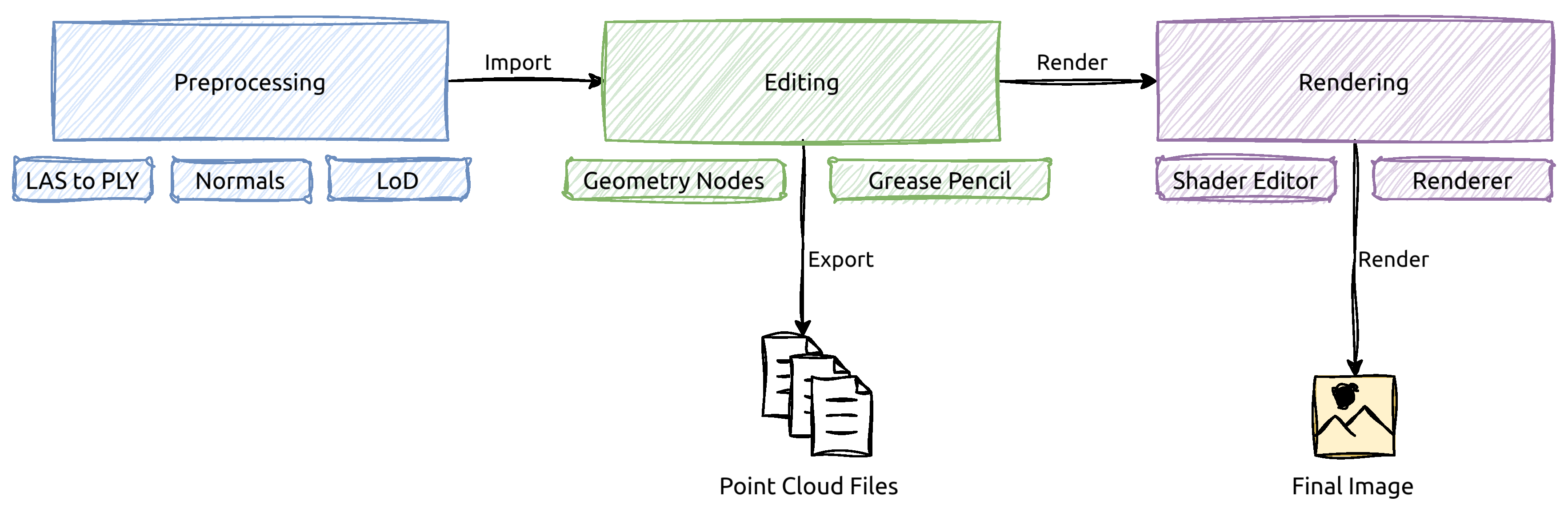
Figure 2.
Our preferred node tree construction. Mesh to Points node could also be placed after other nodes but before Set Material node.
Figure 2.
Our preferred node tree construction. Mesh to Points node could also be placed after other nodes but before Set Material node.

Figure 3.
Example of point copying on a region of point cloud from Tokyo dataset. The bottom left skyscraper was copied, moved to the center of the scene, and rotated.
Figure 3.
Example of point copying on a region of point cloud from Tokyo dataset. The bottom left skyscraper was copied, moved to the center of the scene, and rotated.
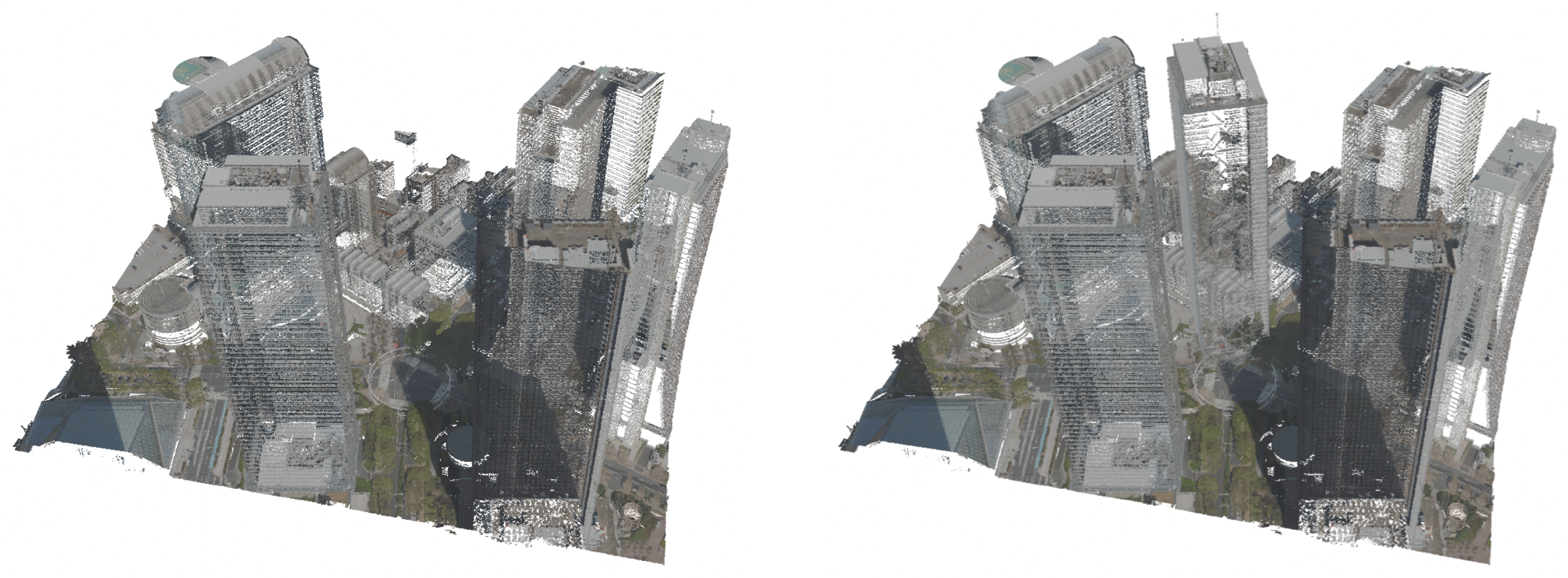
Figure 4.
Example of point removal on a region of point cloud from Tokyo dataset.
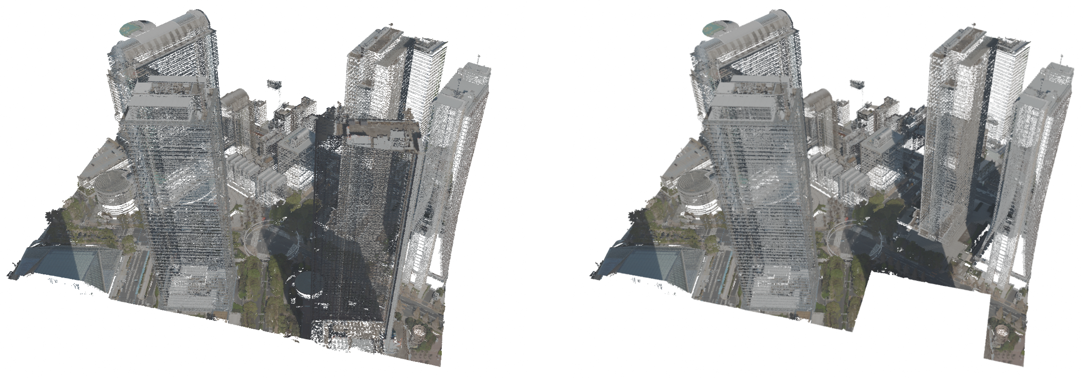
Figure 5.
Example of point drawing operation. On the left, a single Grease Pencil stroke with Geometry Nodes applied to it is presented. On the right, some Grease Pencil strokes are placed in the scene. The Tokyo point cloud and Grease Pencil drawing are separate objects.
Figure 5.
Example of point drawing operation. On the left, a single Grease Pencil stroke with Geometry Nodes applied to it is presented. On the right, some Grease Pencil strokes are placed in the scene. The Tokyo point cloud and Grease Pencil drawing are separate objects.
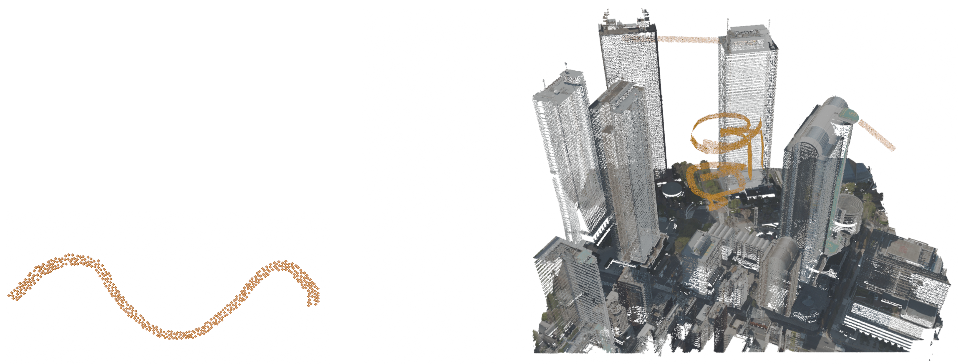
Figure 6.
Example of painting on points, presented on Tokyo dataset.
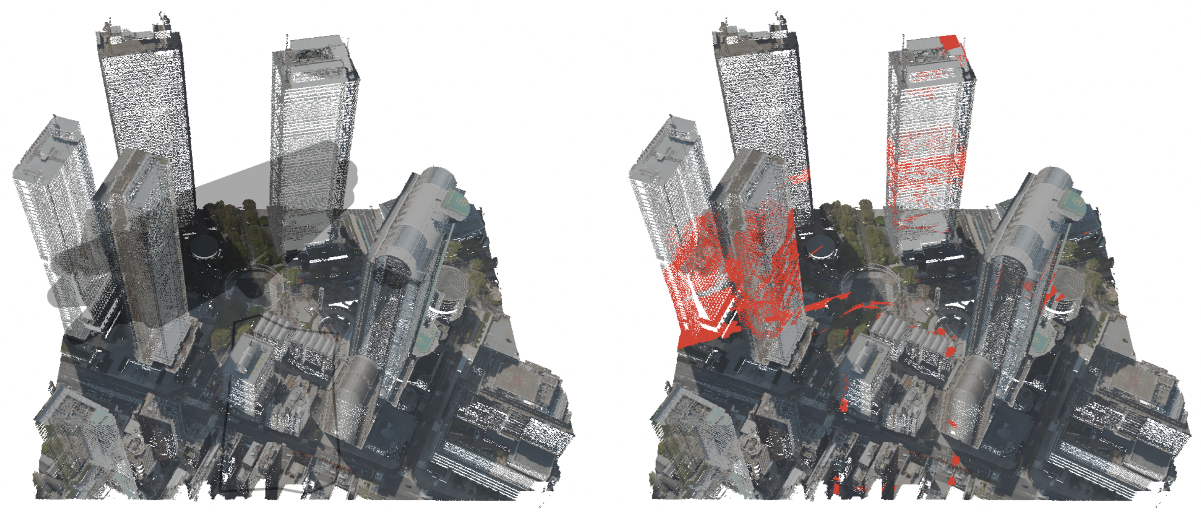
Figure 7.
Example of erasing points, presented on Tokyo dataset.
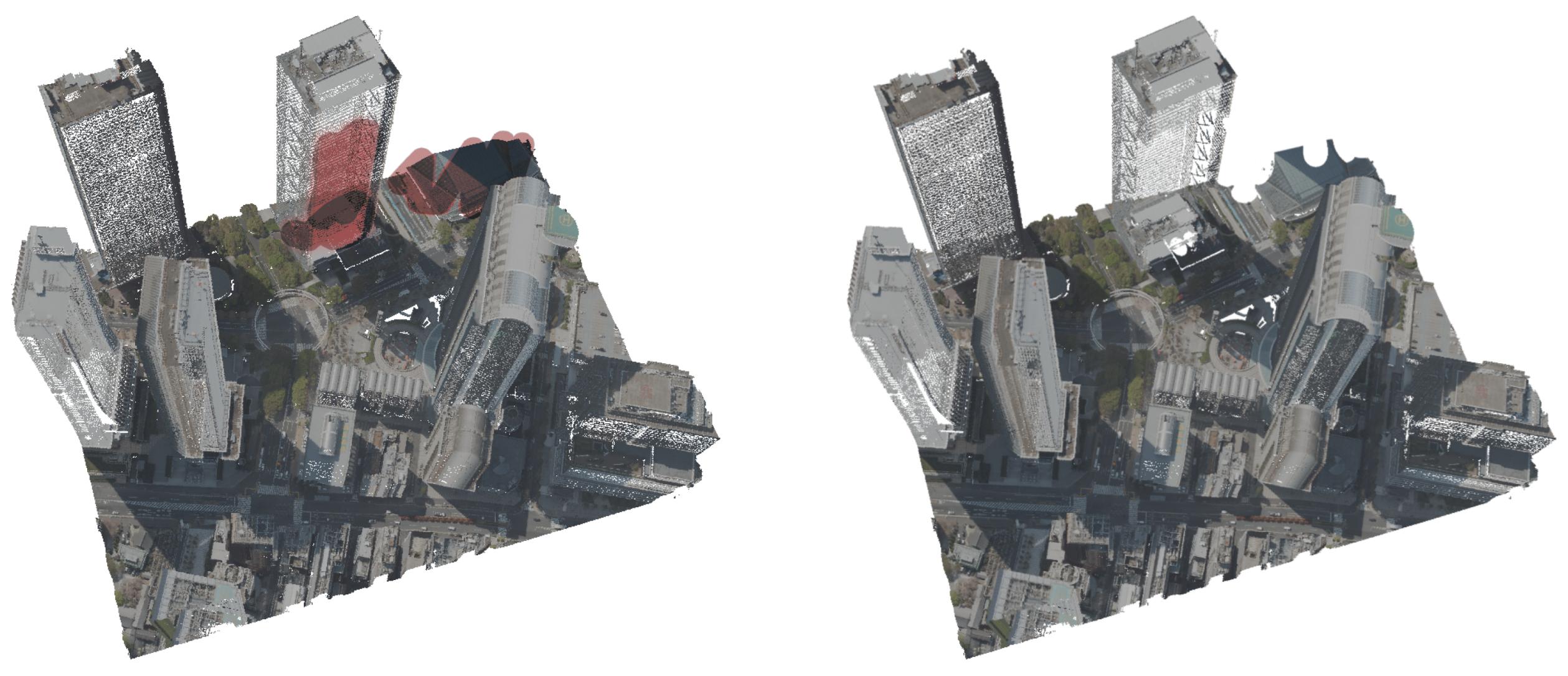
Figure 8.
Example of flattening, presented on Tokyo dataset.
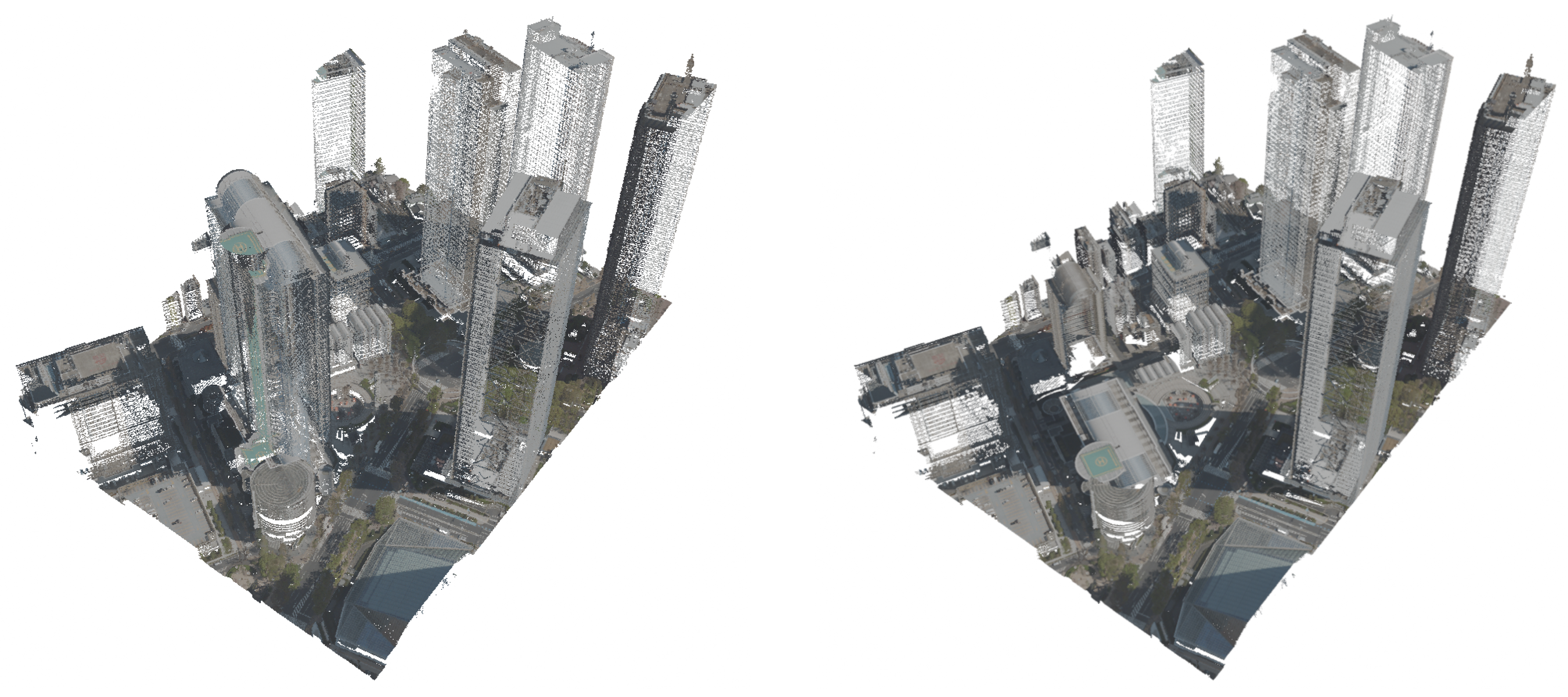
Figure 9.
Example of converting mesh object to point representation. On the left, the mesh object is displayed with a wireframe. Vertex Painting was used to change the vertex color at certain edge angles, and the color attribute was transformed via a Color Ramp node in the material to produce orange and gray hues.
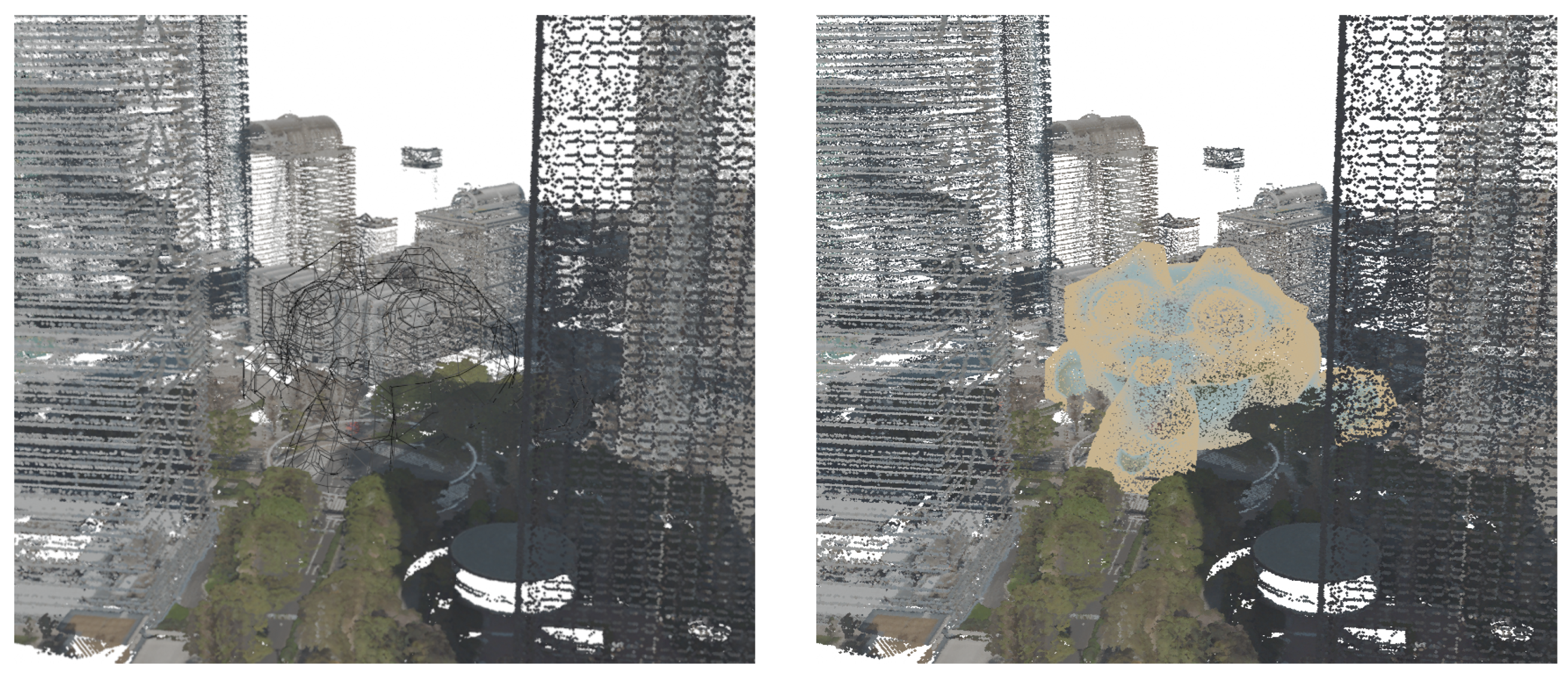
Figure 10.
Geometry Node graphs showcasing examples used in our experiments.
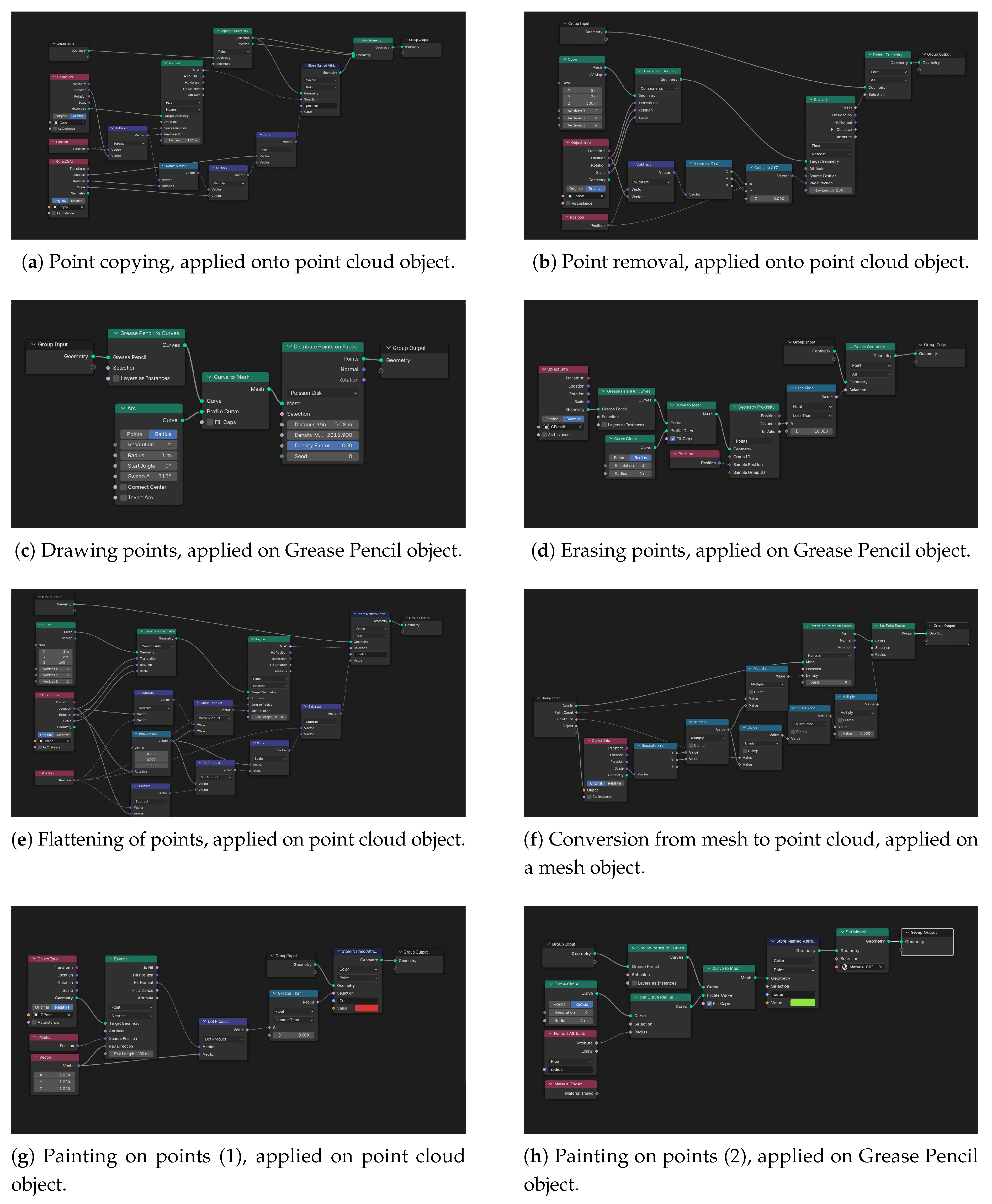
Figure 11.
Renders of the Tokyo dataset in Blender Cycles (first three images) and in Rhino (the 4th image).
Figure 11.
Renders of the Tokyo dataset in Blender Cycles (first three images) and in Rhino (the 4th image).
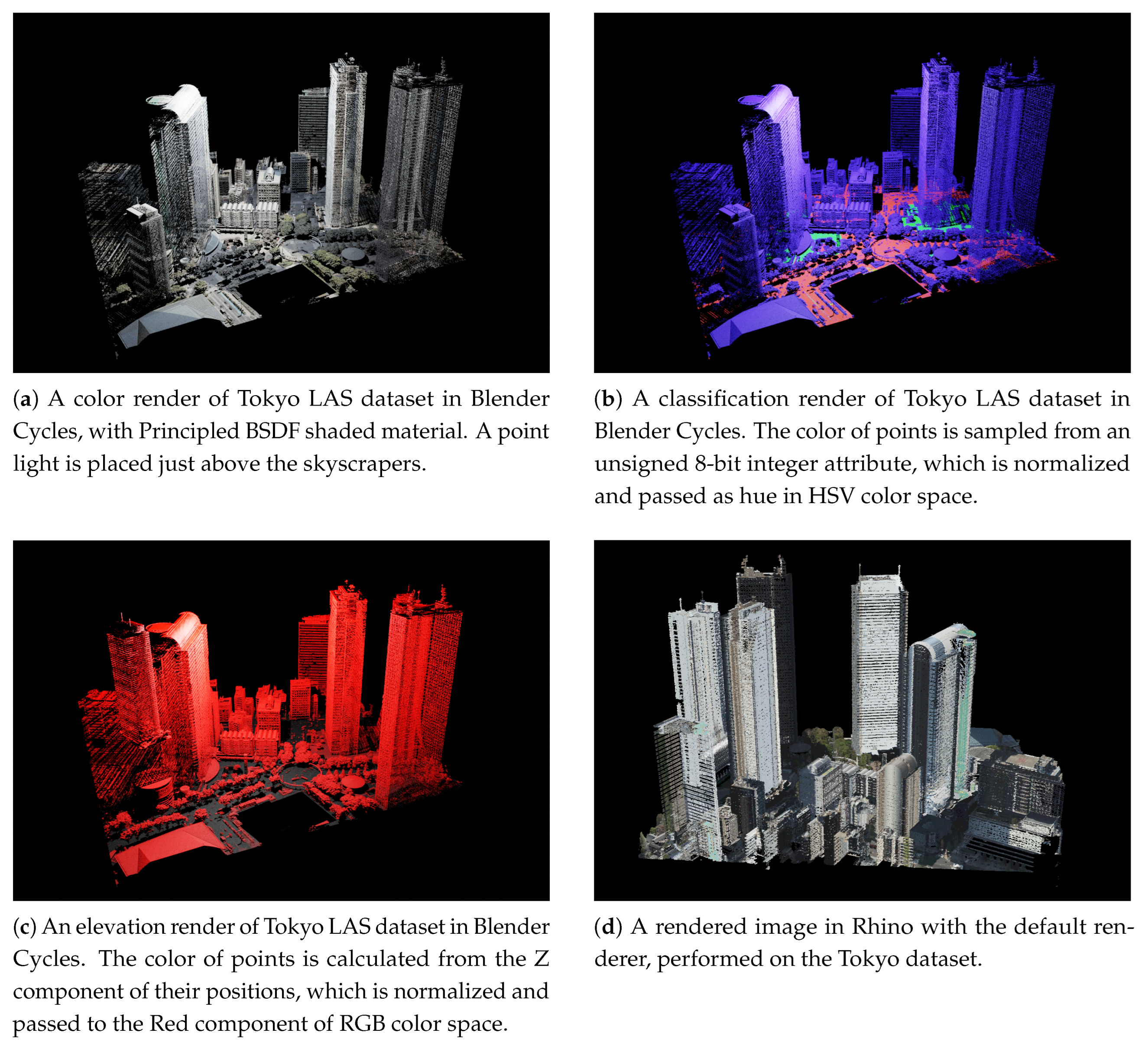

Table 1.
Results of operations on Tokyo LiDAR dataset, performed in Blender with Geometry Nodes. Node Count excludes the input and output node of the observed node group responsible for the operation, and execution time represents the approximate execution time of the observed node group.
Table 1.
Results of operations on Tokyo LiDAR dataset, performed in Blender with Geometry Nodes. Node Count excludes the input and output node of the observed node group responsible for the operation, and execution time represents the approximate execution time of the observed node group.
| Operation | Node Count | Execution Time | Number of points | Bottleneck |
|---|---|---|---|---|
| Point Copying | 10 | 0.29 s | (~340k points) | Join Geometry node |
| Point Removal | 9 | 0.11 s | (~460k points) | Delete Geometry node |
| Drawing Points | 4 | 0.21 s | (~18k points added) | Points on Faces node |
| Erasing Points | 8 | 0.26 s | (~200k points) | Delete Geometry node |
| Coloring Points | 7 + 7* | 0.5 s | (~200k points colored) | Store Named Attribute node |
| Flattening Points | 13 | 0.11 s | (~880k points) | Store Named Attribute node |
| Mesh to Points | 11 | 0.02 s | (~104k points) | Points on Faces node |
* There are two node groups, one applied to the point cloud object and one applied to the Grease Pencil object.
Table 2.
Results of operations on Tokyo LiDAR dataset, performed in Rhinoceros 8 Grasshopper. Execution time represents the approximate execution time of the observed node group.
Table 2.
Results of operations on Tokyo LiDAR dataset, performed in Rhinoceros 8 Grasshopper. Execution time represents the approximate execution time of the observed node group.
| Operation | Node Count | Execution Time | Number of points | Bottleneck |
|---|---|---|---|---|
| Point Copying | 16 | 91 s | (~340k points) | Point in Brep, Construct Point Cloud |
| Point Removal | 9 | 90 s | (~460k points) | Point in Brep, Construct Point Cloud |
| Flattening Points | 19 | 65 s | (~880k points) | Construct Point Cloud |
Table 3.
Measurements of rendered images of Tokyo point cloud. The images were rendered at a resolution of 1920 × 1080 pixels. The middle column notes the material shader applied on points.
Table 3.
Measurements of rendered images of Tokyo point cloud. The images were rendered at a resolution of 1920 × 1080 pixels. The middle column notes the material shader applied on points.
| Renderer | Shader used | Duration |
|---|---|---|
| ]2*Blender EEVEE | Principled BSDF | 3.9 s |
| Emission | 2.8 s | |
| ]2*Blender Cycles | Principled BSDF | 40 s |
| Emission | 19 s | |
| Rhino Renderer | / | < 1 s * |
* The measurement does not include tone-mapping or gamma correction. These could take up to 3 seconds.
Disclaimer/Publisher’s Note: The statements, opinions and data contained in all publications are solely those of the individual author(s) and contributor(s) and not of MDPI and/or the editor(s). MDPI and/or the editor(s) disclaim responsibility for any injury to people or property resulting from any ideas, methods, instructions or products referred to in the content. |
© 2025 by the authors. Licensee MDPI, Basel, Switzerland. This article is an open access article distributed under the terms and conditions of the Creative Commons Attribution (CC BY) license (http://creativecommons.org/licenses/by/4.0/).
Copyright: This open access article is published under a Creative Commons CC BY 4.0 license, which permit the free download, distribution, and reuse, provided that the author and preprint are cited in any reuse.


