
Submitted:
01 March 2025
Posted:
03 March 2025
You are already at the latest version
Abstract
The recycling of cable scrap, particularly from discarded electrical wiring, is gaining significant attention due to the rising demand for copper and the need for sustainable management of electronic waste. Traditionally, mechanical processing has been used to recover copper and plastic from cables. However, this approach is often energy-intensive, time-consuming, and costly in terms of equipment and labor. In this study, we propose a simple microwave technology as an alternative method for fast and efficient recovery of materials from cable scrap, particularly copper and carbon. Microwaves facilitate the separation of plastic, generating carbon and allowing direct copper extraction with minimal energy input. The recovered materials can be reused or repurposed, adding further value to the recycling effort. This approach improves recovery efficiency, offering a more sustainable and cost-effective solution for industrial purposes.
Keywords:
cable scrap
; microwave irradiation
; carbon
; copper metal
; recycling
; plastic waste
1. Introduction
Cables are essential components for transmitting information and electricity. They contain valuable materials like copper and plastic, which make their recovery highly desirable. According to the Brussels-based organization Waste Electrical and Electronic Equipment (WEEE), approximately 1 billion kg of cables were discarded in 2022-enough to circle the earth 107 times. If not adequately managed, heavy metals and microplastics can leach into soil and contaminate water, resulting in loss of a valuable resource and environmental hazard. Recycling becomes therefore crucial to conserve key resources and support sustainable economic growth [1,2,3,4]. Direct recycling, such as mechanical stripping, is the primary means of recovering copper and plastic from cable scrap [1,2,3]. Indirect methods, such as pyrolysis in energy-intensive electric furnaces to extract valuable carbon from the plastic sheath while preserving the copper, have also gained popularity [3,5,6,7,8,9,10]. Incineration in air, thermal decomposition under anoxic conditions, and steam gasification are among the most common heat recovery processes. Both direct and indirect technologies have advantages and limitations and are used interchangeably in cable recycling; however, challenges remain such as the need for faster processing, energy savings, low costs, and high-quality recovered copper [3].
Microwave technology provides an energy-efficient way to rapidly convert plastic waste into valuable carbon at relatively short times [11,12,13,14,15,16,17,18,19,20,21,22]. Microwave-assisted pyrolysis is an eco-friendly waste disposal method that plays an important role in advancing the circular economy. It has been effectively employed for producing biochar and biofuels, thanks to its volumetric and selective heating capabilities, which set it apart from the direct heating used in traditional pyrolysis processes [12]. For instance, Park et al. [11] highlighted the efficiency of microwave-assisted stabilization and carbonization of polyacrylonitrile composites, cutting processing times from hours to minutes. The resulting carbon anodes achieved high nitrogen content (>7 %) and delivered a specific capacity of over 300 mAh·g-1 at 0.1 A·g-1. This approach improves energy efficiency and enhances the electrochemical performance of anodes, positioning microwave processing as a promising method for developing advanced materials for lithium-ion batteries. Similarly, Shi et al. [15] utilized rapid microwave carbonization of natural cellulose nanofibers combined with a graphene initiator to develop high-performance anodes for sodium-ion batteries. This process resulted in an initial capacity of 558 mAh·g-1, significantly higher compared to typical sodium-ion battery anodes. In addition, the materials showed good cycling performance. They observed a capacity of ca. 340 mAh·g-1 after 200 cycles. The inclusion of reduced graphene oxide (rGO) enhanced the microwave absorption of CNFs, facilitating ultrafast carbonization and improving the structural properties of the resulting carbon. Additionally, Brazil et al. [20] explored the microwave-assisted production of activated carbon from lignocellulosic waste in a modified domestic microwave oven with high surface areas ca. 900 m2·g-1 and pore volumes of 0.5 cm3·g-1. These activated carbons show excellent adsorption properties, particularly for removing contaminants like methylene blue (90 mg·g-1). Wang et al. [21] explored the use of coconut husk carbon in the microwave co-pyrolysis of polyethylene terephthalate (PET) and low-density polyethylene (LDPE). At 550 °C, the liquid yield reached 52%, with a high content of monocyclic aromatic hydrocarbons at 83%. The study also highlighted a positive synergistic effect between PET and LDPE, demonstrating enhanced liquid yield and improved aromatic content through the combined pyrolysis of the two precursors. A continuous microwave-assisted pyrolysis system was developed by Zhou et al. [22] for converting plastics into oil. Higher pyrolysis temperatures facilitated the cracking of waxes, resulting in lighter and more stable hydrocarbons. Using a ZSM-5 catalyst at 620 °C, the liquid phase yield reached 49%, with the product containing 73% gasoline-range hydrocarbons, including 45% aromatics and 25% isomerized aliphatics.
Microwave technology is particularly suited for carbonizing plastics that already contain metal. Under microwave irradiation, the temperature of the metal core rises rapidly due to Ohmic heating by the electromagnetic radiation, causing the plastic to carbonize. This approach has been successfully applied to various items, including tires, toothpaste tubes, multilayer packaging, pencils, printed circuit boards, CDs and snack bags [23,24,25,26,27,28,29]. For cables microwaves have primarily been used in fuel-generation applications [30,31,32]. However, no report in the literature covers the microwave synthesis, detailed characterization, or applications of chars derived from cable scrap including simultaneous copper extraction.
In this paper we demonstrate an efficient, sustainable, and cost-effective method for recovering valuable materials from copper cable scrap, a common by-product of the electronics industry. Specifically, we show that microwave technology accelerates the thermal degradation of the plastic component into valuable carbon, facilitating clean copper recovery with minimal energy input. The recovered copper retains its lustrous appearance and conductive nature. In addition, we provide detailed characterization of the derived carbon using several analytical techniques and discussing potential applications for the recovered materials. The advantages of the method are selective material separation, efficient processing and reduced processing time-all of which make the process attractive and promising for large-scale industrial implementation.
2. Materials and Methods
All chemicals and solvents were purchased from Sigma-Aldrich. Experiments were conducted using a household microwave oven (frequency 2.45 GHz, wavelength ca. 12 cm). Microwave treatment was carried out in a fume hood. Prior to microwave treatment, thin single-strand copper cable (diameter 1.5 mm) with polyvinyl chloride (PVC) insulation was cut into 2-2.5 cm-long pieces. Note that the polymer sheath in the cable contains calcium carbonate (CaCO3), an inexpensive filler adding electrical insulation, weight reduction, and thermal stability.
Microwave carbonization of cable scrap is conducted in the presence of oxygen, leading to the release of organic volatiles from the combustion of the polymer sheath. To minimize these emissions for future industrial applications, a promising approach is to perform microwave carbonization in an inert nitrogen atmosphere, thereby eliminating combustion by removing oxygen. Furthermore, incorporating a filtration system to capture and neutralize volatiles during the process could further reduce emissions. These modifications would support a more sustainable and safer carbonization process while mitigating the release of organic volatiles [3,33].
2.1. Microwave Separation of Copper and Carbon
Several cable pieces (10-20) were placed on a silica ceramic crucible in a microwave oven and irradiated in air for 30 s at 700 W under rotation (operating at less than 700 W generates sticky masses of carbon and polymer melt). The plasma generated by the copper wires ignited the cables, causing carbonization of the plastic part. The as-formed carbon adhered weakly to the copper wires and was separated mechanically by hand abrading. Any remaining carbon was removed by mild sonication in water for a few minutes in an ultrasound bath. The recovered carbon was treated with concentrated HNO3 aqueous solution (65%) to remove microscopic copper particles and CaCO3. It was then treated with 48% HF, 30% KOH, and hot 3 M HCl aqueous solutions to remove any silica residue from the ceramic crucible. The solid was thoroughly washed with deionized water until neutral pH, and then acetone until no coloration of the solvent, prior to drying at 100 °C. The copper is recovered practically quantitatively. While the process has yet to be optimized the yield is 1 g of carbon per 10 m cable.
2.2. Characterization Techniques and Instrumentation
X-ray diffraction (XRD) patterns were obtained using a glass substrate for copper and a background-free Si wafer for carbon, with Cu Kα radiation (λ = 1.54 Å) from a Bruker Advance D8 diffractometer. Samples were scanned over a 2-80° 2θ range, in steps of 0.02° (2θ), at a rate of 0.2 s per step.
Raman spectra were recorded with a micro-Raman system RM 1000 Renishaw using a laser excitation line at 532 nm.
X-ray photoelectron spectroscopy (XPS) measurements were obtained by a Thermo Scientific Nexsa G2 Spectrometer at operating pressure 1 x 10⁻⁹ Torr and monochromatic Al Kα x-rays (1486.6 eV) with photoelectrons collected from a 200 μm diameter analysis spot at a 90° emission angle and a source to analyzer angle of 54.7°. A hemispherical analyzer determined electron kinetic energy, using pass energy of 200 eV for wide/survey scans, and 50 eV for high resolution scans. A flood gun was used for charge neutralization of non-conductive samples. Spectra were deconvoluted with the CasaXPS software.
Scanning electron microscopy (SEM) images were obtained using a JEOL JSM-6510 LV SEM Microscope equipped with an X-Act EDS-detector by Oxford Instruments.
Transmission electron microscopy (TEM) images were collected using FEI Tecani 12 BioTwin TEM. 1% w/v suspensions were prepared in ethanol and dropped-casted into carbon coated copper grids.
Atomic force microscopy (AFM) experiments were conducted in peak force tapping mode on a Multimode 8, Nanoscope 6, using RTESPA-525 cantilevers with a tip radius of 8 nm. The sample was drop-casted onto silicon wafers prior to imaging.
Nitrogen (N2) adsorption-desorption isotherms were measured by a Micromeritics ASAP 2460 by using ultrahigh pure N2 (99.999 %). The sample was outgassed for 18 h under vacuum (10-4 mbar) at 140 °C. Porosimetry isotherms were recorded at 77 K using a liquid N2 Dewar vessel at a relative pressure (P/P0) of 10-2 to 0.99.
A Lakeshore table-top probe station was used to design contacts to the copper wire samples and a Keithley 2400 source meter (source current 1 A) to perform the 4-probe resistance measurements.
3. Results and Discussion
3.1. Microwave Pyrolysis of Cable Scrap
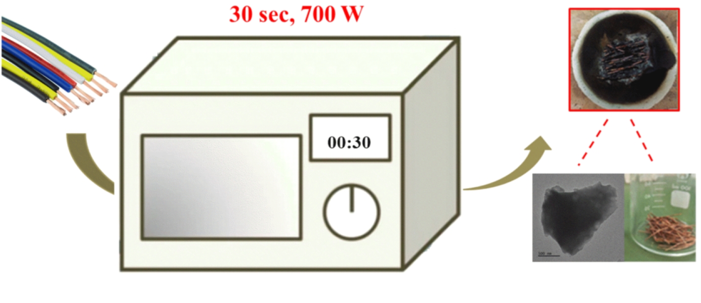
The process for copper recovery with simultaneous carbon synthesis is shown in Figure 1. Microwave irradiation permits the simultaneous conversion of the plastic to carbon and the separation of copper from the cables by completing the process in a short time (30 s) with low energy consumption. The recovered copper retains its lustrous appearance indicating that no oxidation to CuO has occurred. We hypothesize that the polymer turned into a carbon coating protects the metal against oxidation as shown by the following displacement reaction:
C + 2 CuO → 2 Cu + CO2
Analysis of copper cable wire through XRD, XPS, and SEM before and after microwave treatment reveals no significant structural or compositional changes. On the other hand, carbon is produced from the carbonization of PVC in air through a series of chemical transformations, including dechlorination, cyclization, aromatization, and oxidation mediated by free radicals, ultimately resulting in char formation. Each of these processes is inherently endothermic, requiring a continuous heat supply. Under microwave conditions, this heat is sufficiently supplied through Ohmic heating, where electrical currents induced by the microwave field generate resistive heating in the copper metal, providing the necessary thermal energy for the reactions to proceed. Notably, the 2.45 GHz microwaves used in this study have a wavelength of approximately 12 cm, while the cable lengths ranged from 2 to 2.5 cm. This length is close to one-quarter of the wavelength (3 cm), where the standing wave's intensity is at its peak. As a result, copper wires of this specific length interact strongly with the microwaves, leading to significant heating and pyrolysis [33].
3.2. Characterization of Cu Metal and Carbon Derived from Cables’ PVC Cover
3.2.1. X–Ray Diffraction (XRD) Analysis of Cu Metal (Before and After Process) and Carbon Derived from Cables’ PVC Cover
The XRD patterns (Figure 2) are characteristic and consistent with Cu metal, suggesting that the crystalline structure of copper remains unchanged.
The XRD pattern of the derived carbon (Figure 3) is consistent with amorphous carbon [34] showing broad reflections with decreasing intensity corresponding to graphite's (002) and (100) planes. The (002) reflection is attributed to stacked layers with a Bragg interlayer spacing d002 = 3.6 Å (λ = 2 d002 sinθ), slightly larger than that of crystalline graphite (d002 = 3.34 Å) [35]. Applying the Scherrer equation to the (002) peak (Lc = 0.9 λ / β cosθ) resulted in particle thickness Lc = 2 nm along the c-axis, equivalent to stacks of Nc = 6-7 layers [36]. On the other hand, the (100) reflection is associated with the in-plane crystallinity of a single layer. Using the modified Scherrer equation (La = 1.84 λ / β cosθ) [37], the size of the nanocrystalline graphitic domains La was 4 nm along the a-axis. Sharp reflections of CaF2 [38], an insoluble by-product formed by the HF treatment, persist even after EDTA treatment suggesting that calcium is retained within the carbon matrix. According to thermal gravimetric analysis (TGA) in air, the product consists of nearly 90% carbon and 10% calcium fluoride (CaF2).
3.2.2. Raman Analysis of Carbon Derived from Cables’ PVC Cover
The Raman spectrum (Figure 4) similarly supports the presence of amorphous carbon [34]. The spectrum contains two broad bands: 1594 cm-1 (G band) and 1350 cm-1 (D band). The G and D bands are formed by the E2g and A1' vibrational modes of graphene's hexagonal rings, respectively. The G band is typically associated with sp2 graphitic domains, whereas the D band is linked with sp3 aliphatic domains. These bands have a higher intensity ratio (ID/IG = 0.8) than crystalline graphite (ID/IG = 0.1-0.2) [35]. Based on this value, the size of the nanocrystalline graphitic domains La along the a-axis was independently determined at 5.5 nm using the formula La = 4.4 (ID/IG)-1 [39], which is consistent with that derived from the XRD pattern.
3.2.3. X–Ray Photoelectron Spectroscopy (XPS) Analysis of Cu Metal (Before and After Process) and Carbon Derived from Cables’ PVC Cover
XPS survey analysis of Cu metal before and after microwave treatment is also similar indicating uniform surface characteristics in terms of elemental composition (Figure 5, left). The Cu2p XPS spectra (Figure 5, right) shows no variation in chemical state, indicating that the copper’s oxidation state or surface chemistry was not impacted.
The XPS survey spectrum of the carbon reveals the presence of C (68.7 at. %), O (14.8 at. %) and N (15.7 at. %) with minor contributions from Ca (0.3 at. %) and Cl (0.5 at. %) (Figure 6a). Oxygen is expected to be present since the microwave treatment was conducted in air. In addition, nitrogen and chlorine are derived from the acid treatments and the chlorine in PVC, respectively. The high-resolution C1s spectrum shows a dominant component (65.7 %) at a binding energy of 284.8 eV due to C-C/C=C bonds, followed by oxidized carbon species at higher binding energies and decreasing order C-O > C=O > O-C=O (Figure 6b) [40,41]. XPS shows no fluorine at all and a very small amount of calcium that appears inconsistent with the XRD data presented above. We note that XPS is a surface-sensitive technique that typically probes the top 5-10 nm of the sample. Hence, the results suggest that both F and Ca are embedded in the interior of the carbon matrix as CaF2.
3.2.4. Microscopy Analysis of Cu Metal (Before and After Process) and Carbon Derived from Cables’ PVC Cover
SEM images of Cu metal (Figure 7) confirm that the surface morphology of the copper wire remained practically intact. These findings indicate that the copper wire is resistant to structural, chemical, and morphological changes under the microwave conditions. Subsequently, electrical conductivity measurements via the 4-probe method show similar values before and after microwave treatment (6.8·107 and 6.5·107 S·m-1, respectively). These values are very close to those reported in the literature for copper (5.80·107 - 5.95·107 S·m-1).
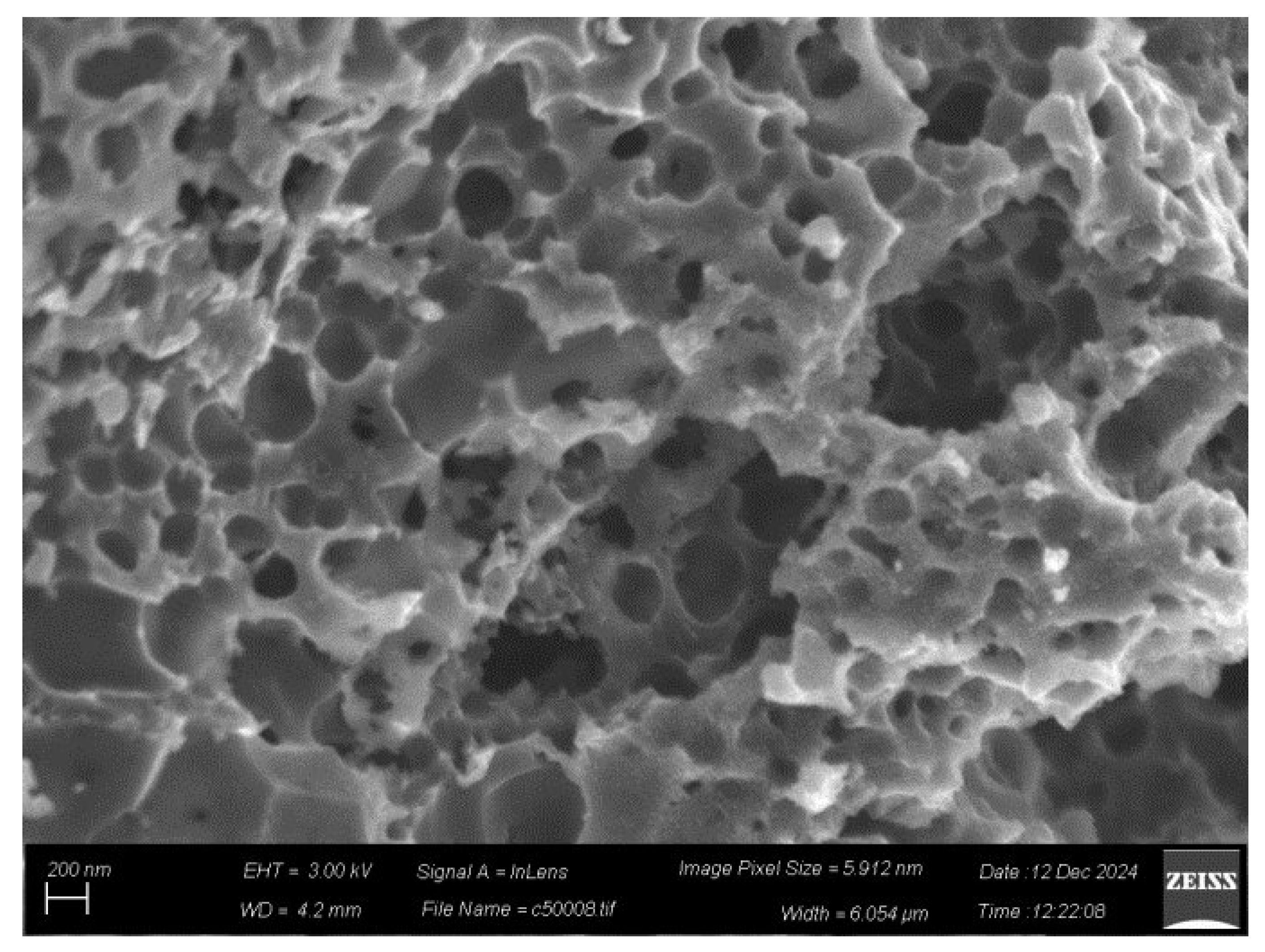
SEM imaging of carbon shows predominantly macroporous (pore size > 50 nm) carbon particles with swiss-cheese morphology (Figure 8, top). We attribute this morphology to the presence of CaCO3 filler particles in the PVC acting as porogen [42,43]. In addition, compact particles with platy morphology were also found, but in much fewer numbers (not shown). Energy dispersive spectroscopy (EDS) elemental mapping shows that the sample is mainly composed of C (81.2 wt. %) and O (9.1 wt. %) (Figure 8, bottom), consistent with XPS, followed by Ca (4.1 wt. %), Cl (5.2 wt. %), K (0.2 wt. %) and Si (0.2 wt. %). The traces of silicon and potassium come from the silica ceramic crucible and the KOH base treatment, respectively. No nitrogen was detected in the sample’s bulk composition, implying that N is only present on the surface (as detected by XPS). Regarding the absence of fluorine, we note that as a light element it is difficult to detect by EDS especially when present in small amounts.
TEM images indicate the presence of compact carbon nanosheets (Figure 9) with micron- or submicron-sized lateral dimensions. Furthermore, they show a multilayer structure along the edges due to stacks of individual layers, which is a common property of layered-like carbon nanomaterials.
The average thickness of the nanosheets measured using AFM was 2.6 nm (Figure 10). This number is close to the Lc value of 2 nm obtained from XRD and the Scherrer equation. Based on the TEM and AFM measurements, the lack of any kind of porosity in the nanosheets suggests that the macroporosity observed in the SEM arises from particle packing and interparticle voids created by the removal of CaCO3 by acid dissolution.
3.2.5. Nitrogen (N2) Porosimetry Analysis of Carbon Derived from Cables’ PVC Cover
The N2 adsorption-desorption isotherm of carbon shows a mixed H2 and H3 type hysteresis loop. The hysteresis loop was simulated using the CPSM model (Figure 11a), indicating a mesoporous structure with cylindrical pores arising from aggregates of plate-like particles [44,45]. Similar to macropores, such mesopores originate from CaCO3, which acts as a porogen [42,43]. The BET and CPSM techniques were used to calculate the specific surface area [46]. The SBET was 141 m2·g-1; the corrected SCPSM, considering pore curvature effects [46], was 153 m2·g-1. These two values were close because of the mesopore nature of the material’s pore structure. This is evidenced by the pore size distributions estimated by BJH, CPSM, and DFT methods [46,47] and presented in Figure 11b-d. All three curves showed two distinct groups of pores, with 0.25 cm3 ·g-1 total pore volume. The first group of pores has a diameter of 1-15 nm while the second group in the region 15-35 nm. From the above we conclude that in addition to the macroporosity which is also seen in the SEM, the material also has a mesoporous structure. Mesopores contribute significantly more to the sample's specific surface area than the macropores. The microporosity fraction estimated from the CPSM simulation was 0.3%, which is insignificant.
3.3. Microwave vs Conventional Pyrolysis of Cable Scrap
Heating experiments in conventional electric box oven showed that the cable wires ignite at 500 °C, producing a yellow flame similar to that observed in the microwave oven. Based on this, we estimate an average temperature of approximately 500 °C in the microwave oven. However, the plasma generated by the heated metal under microwave irradiation likely results in higher localized temperatures. This estimated temperature is consistent with the ignition temperature of PVC plastic in air (485 °C).
In order to compare microwave carbonization with conventional pyrolysis for cable scrap, heating experiments were conducted using an electric box oven (1300 W) at 500 °C in air and 2-2.5 cm-long samples. These conditions match reasonably well those used in microwave heating (700 W). Due to the slower heating rate of the conventional oven compared to microwave processing, the heating duration was extended to at least 5 min, in contrast to 30 s required in the microwave oven. This adjustment ensured effective carbonization of the polymer sheath and prevented the formation of a sticky polymer melt, which could otherwise hinder the process. Based on simple calculations that take into account power consumption, conversion rate (30% for box ovens, 70% for microwave ovens), and duration, microwave heating has an energy efficiency of 80%. After conventional pyrolysis the carbon and copper metal were mechanically separated, with the recovered carbon undergoing similar acid treatments as described in the experimental section. Copper is practically extracted quantitatively, while the carbon yield is lower (0.5 g per 10 m cable) due to prolonged exposure in air, which promotes combustion and reduces carbon residue formation.
Further analysis reveals notable differences compared to microwave processing. The XRD pattern for the metal (Figure 12) confirms the presence of Cu metal but also indicates carbon residues that cannot be mechanically removed.
Similarly, XPS shows elevated carbon content and greater surface oxidation (Figure 13).
In line with these observations, SEM clearly reveals carbon residues on the metal wire's surface (Figure 14). The molten polymer sheath has sufficient time to infiltrate metal cracks, leaving behind carbon particles after carbonization that stains the surface. Additionally, the conductivity of the Cu processed conventionally is lower by an order of magnitude 1.96·106 S·m-1. This decrease is attributed to prolonged heating during conventional processing and increased oxygen exposure. These results suggest that the copper obtained through conventional heating is of lower quality than that produced via microwave heating.
With respect to carbon, the XRD reveals an amorphous structure with inorganic phase impurities that persist even after acid treatments (Figure 15).
XPS further indicates that this carbon is more oxidized compared to that obtained through microwave heating similar to the Cu discussed above (Figure 16).
SEM shows a macroporous structure comparable to that of the microwave-derived carbon (Figure 17).
However, the specific surface area of the former is < 10 m2·g-1, much smaller than that of microwave-derived carbon. The lower surface area is either due to the lack of micro-/mesoporosity or blockage of micro-/mesopores by impurities.
All in all, microwave pyrolysis offers significant advantages over conventional pyrolysis. One of its key benefits is speed, as microwave pyrolysis is considerably faster, reducing processing time. The method is more energy efficient with an efficiency of 80%, making it a more sustainable and cost-effective option compared to traditional pyrolysis. Additionally, microwave pyrolysis results in a higher quality of recovered copper with minimal amount of impurities. Another notable advantage is the improved carbon yield and higher surface area from the carbonization of PVC sheath. This leads to a higher quantity of active carbon products, which can be further utilized or sold.
3.4. Thoughts for Cable Scrap Valorization
The copper and carbon recovered from cable scrap are valuable for numerous practical applications. Copper chops, for example, play a key role in the recycling of scrap copper, where they are reused to create new copper products (electronic appliances, building material, consumer products) [48]. The process conserves natural resources and is more energy-efficient than mining and refining virgin copper. What’s more, copper chops are useful in metallurgy (smelting, cast molding, alloying, refining, plating), as catalysts in chemical industry (production of methanol, desulfurization of fuels), in mechanical reinforcement (gypsum), and in resin art/epoxy crafts (orgonite pucks). Carbon, on the other hand, plays a crucial role in several processes, including extractive metallurgy, gunpowder production, paint formulations, and inks, where carbon supply is in high demand [23,25,49,50,51]. Furthermore, the porosity of carbon, combined with its oxidized surface, could enhance its effectiveness in adsorption processes (e.g., in filters). The porous structure provides a large surface area, while the oxidized sites offer active centers for binding various molecules. Given the volume of scrap and the quality of the materials generated, further process optimization is likely to yield significant amounts of copper and carbon.
4. Conclusions
We demonstrate that microwave treatment of cable scrap is a highly effective and fast approach for copper recovery and carbon synthesis, both of which are valuable for various practical applications. The recovered copper retains its lustrous appearance and conductivity. In addition, the process produces disordered porous carbon with a meso/macroporous texture resulting from particle packing, void spaces generated during microwave heating, as well as the presence of CaCO3 particles in the cables that act as porogen. By integrating copper recovery with carbon valorization, the microwave process offers a sustainable approach, transforming cable scrap into valuable resources for multiple industries, while promoting waste reduction and resource efficiency. The approach could also be adapted for other types of cable with different metals (e.g., aluminum) or insulation materials (e.g., silicone) to recycle and synthesize various materials including ceramic powders.
Author Contributions
Conceptualization, A.B.B., E.P.G., C.E.S. and M.A.K.; methodology, N.C., D.P.G, A.B.B., C.E.S. and M.A.K.; software, N.C., and D.M.; validation, A.B.B., N.C., E.P.G., C.E.S., M.A.K.; formal analysis, D.P.G., D.M., and A.A.; investigation, N.C., D.M., D.P.G., A.A.; resources, A.B.B., E.P.G., C.E.S., and M.A.K.; data curation, D.M, and N.C.; writing—original draft preparation, A.B.B., N.C., E.P.G., C.E.S. and M.A.K.; writing—review and editing, A.B.B., N.C., E.P.G., C.E.S. and M.A.K.; visualization, A.B.B., E.P.G., A.A., M.A.K., and C.E.S.; supervision, A.B.B., C.E.S. and M.A.K.; project administration, A.B.B., E.P.G., M.A.K., and C.E.S.; and funding acquisition, A.B.B., A.A., E.P.G., M.A.K., and C.E.S.; All authors have read and agreed to the published version of the manuscript.
Data Availability Statement
The data presented in this study are available on request from the corresponding author.
Acknowledgments
We acknowledge support of this work by the project “Advanced Nanostructured Materials for Sustainable Growth: Green Energy Production/Storage, Energy Saving and Environmental Remediation” (TAEDR-0535821) which is implemented under the action “Flagship actions in interdisciplinary scientific fields with a special focus on the productive fabric” (ID 16618), Greece 2.0-National Recovery and Resilience Fund and funded by European Union NextGenerationEU. The research project is implemented in the framework of H.F.R.I. Call “Basic research Financing (Horizontal support of all Sciences)” under the National Recovery and Resilience Plan “Greece 2.0” funded by the European Union-NextGenerationEU (H.F.R.I. Project Number: 15949). This work made use of the Cornell Center for Materials Research (CCMR) shared instrumentation facility. The authors acknowledge support by the Center for Alkaline-Based Energy Solutions (CABES), part of the Energy Frontier Research Center (EFRC) program supported by the U.S. Department of Energy, under Grant DE-SC-0019445.
Conflicts of Interest
The authors declare that they have no known competing financial interests or personal relationships that could have appeared to influence the work reported in this paper.
References
- H. Kumar, S. Kumagai, Y. Saito, T. Yoshioka, Latest trends and challenges in PVC and copper recovery technologies for end-of-life thin cables, Waste Manag. 174 (2024) 400-410. [CrossRef]
- E. H. Tanabe, R. M. Silva, D. L. Oliveira Júnior, D. A. Bertuol, Recovery of valuable metals from waste cables by employing mechanical processing followed by spouted bed elutriation, Particuology 45 (2019) 74-80. [CrossRef]
- L. Li, G. Liu, D. Pan, W. Wang, Y. Wu, T. Zuo, Overview of the recycling technology for copper-containing cables, Resour. Conserv. Recycl. 126 (2017) 132-140. [CrossRef]
- W. Zhang, Z. Li, S. Dong, P. Qian, S. Ye, S. Hu, B. Xia, C. Wang, Analyzing the environmental impact of copper-based mixed waste recycling-a LCA case study in China, J. Clean. Prod. 284 (2021) 125256. [CrossRef]
- C. Khaobang, N. Kathongthung, P. Phitsuwan, P. Sitthichirachat, H. Wibowo, C. Areeprasert, In-situ adsorptive pyrolysis of e-waste using coal and rice husk fly ash as alternative adsorbents for energy and precious metal recovery by solvent extraction, J. Anal. Appl. Pyrol. 179 (2024) 106465. [CrossRef]
- Y. Kwak, J. Eom, H. Nam, C. Nam, Upcycling of PVC waste to high-value sorbent with KOH-activation for efficient removal of organic dyes, Chemosphere 359 (2024) 142283. [CrossRef]
- R. Mota-Panizio, A. Assis, L. Carmo-Calado, C. Nobre, A. Longo, J. Silveira, M. M. Goncalves, P. Brito, Production, characterization, and activation of biochars from a mixture of waste insulation electric cables (WIEC) and waste lignocellulosic biomass (WLB), C 9 (2023) 49. [CrossRef]
- Z. Wu, Y. Zhang, X. Chen, N. Deng, The pilot scale test on the recycling of copper from the scrap cables by using the pyrolysis, Adv. Inf. Sci. Serv. Sci. 4 (2012) 593-600.
- de Marco, B. M. Caballero, M. J. Chomón, M. F. Laresgoiti, A. Torres, G. Fernández, S. Arnaiz, Pyrolysis of electrical and electronic wastes, J. Anal. Appl. Pyrol. 82 (2008) 179-183. [CrossRef]
- A. Chaala, H. Darmstadt, C. Roy, Vacuum pyrolysis of electric cable wastes, J. Anal. Appl. Pyrol. 39 (1997) 79-96. [CrossRef]
- Park, Y. Lee, S. Park, H. Jin, J. T. Lee, D. Choi, Microwave-mediated stabilization and carbonization of polyacrylonitrile/Super-P composite: carbon anodes with high nitrogen content for lithium ion batteries, Chem. Mater. 35 (2023) 9182-9191. [CrossRef]
- M. S. Selvam, B. Paramasivan, Microwave assisted carbonization and activation of biochar for energy-environment nexus: a review, Chemosphere 286 (2022) 131631.
- E. V. Matveev, A. I. Gajdar, B. A. Lapshinov, A. V. Mamontov, V. V. Berestov, Microwave carbonization of cotton fiber for production of carbon materials, Inorg. Mater.: Appl. Res. 13 (2022) 549-559. [CrossRef]
- Ş. Ö. Teğin, Ö. Şahin, O. Baytar, M. S. İzgi, Preparation and characterization of activated carbon from almond shell by microwave-assisted using ZnCl2 activator, Int. J. Chem. Technol. 4 (2020) 130-137. [CrossRef]
- Q. Shi, D. Liu, Y. Wang, Y. Zhao, X. Yang, J. Huang, High-performance sodium-ion battery anode via rapid microwave carbonization of natural cellulose nanofibers with graphene initiator, Small 15 (2019) 1901724. [CrossRef]
- M. S. Izgi, C. Saka, O. Baytar, G. Saraçoğlu, Ö. Şahin, Preparation and characterization of activated carbon from microwave and conventional heated almond shells using phosphoric acid activation, Anal. Lett. 52 (2019) 772-789. [CrossRef]
- E. M. Villota, H. Lei, M. Qian, Z. Yang, S. M. A. Villota, Y. Zhang, G. Yadavalli, Optimizing microwave-assisted pyrolysis of phosphoric acid-activated biomass: impact of concentration on heating rate and carbonization time, ACS Sustain. Chem. Eng. 6 (2018) 1318-1326. [CrossRef]
- Y. M. Sharif, C. Saka, O. Baytar, Ö. Şahin, Preparation and characterization of activated carbon from sesame seed shells by microwave and conventional heating with zinc chloride activation, Anal. Lett. 51 (2018) 2733-2746. [CrossRef]
- S.-Y. Kim, S. Y. Kim, S. Lee, S. Jo, Y.-H. Im, H.-S. Lee, Microwave plasma carbonization for the fabrication of polyacrylonitrile-based carbon fiber, Polymer 56 (2015) 590-595. [CrossRef]
- T. R. Brazil, M. Gonçalves, E. G. R. dos Anjos, M. S. de Oliveira Jr., M. C. Rezende, Microwave-assisted production of activated carbon in an adapted domestic oven from lignocellulosic waste, Biomass Conv. Bioref. 14 (2024) 255-268.
- X. Wang, Y. Peng, R. Zhou, L. Fan, Q. Zhang, X. Cui, Q. Wu, Y. Zeng, X. Tian, L. Ke, R. Ruan, Y. Wang, Production of monocyclic aromatic hydrocarbons from microwave co-pyrolysis of polyethylene terephthalate and low-density polyethylene using coconut husk carbon as microwave absorbent, Chem. Eng. J. 488 (2024) 150732. [CrossRef]
- N. Zhou, L. Dai, Y. Lv, H. Li, W. Deng, F. Guo, P. Chen, H. Lei, R. Ruan, Catalytic pyrolysis of plastic wastes in a continuous microwave assisted pyrolysis system for fuel production, Chem. Eng. J. 418 (2021) 129412. [CrossRef]
- A. B. Bourlinos, K. Spyrou, D. Moschovas, A. Avgeropoulos, C. Salmas, M. A. Karakassides, Fast microwave carbonization of aluminum-coated plastic wastes and perspectives: the examples of CDs and snack bags, Next Mater. 6 (2025) 100333. [CrossRef]
- L. Yaqoob, T. Noor, N. Iqbal, Conversion of plastic waste to carbon-based compounds and application in energy storage devices, ACS Omega 7 (2022) 13403-13435. [CrossRef]
- N. Chalmpes, G. Asimakopoulos, M. Baikousi, C. E. Salmas, D. Moschovas, A. Avgeropoulos, A. B. Bourlinos, I. Tantis, A. Bakandritsos, D. Gournis, M. A. Karakassides, Microwave synthesis, characterization and perspectives of wood pencil-derived carbon, Appl. Sci. 12 (2022) 410. [CrossRef]
- Undri, L. Rosi, M. Frediani, P. Frediani, Fuel from microwave assisted pyrolysis of waste multilayer packaging beverage, Fuel 133 (2014) 7-16. [CrossRef]
- Undri, B. Sacchi, E. Cantisani, N. Toccafondi, L. Rosi, M. Frediani, P. Frediani, Carbon from microwave assisted pyrolysis of waste tires, J. Anal. Appl. Pyrol. 104 (2013) 396-404. [CrossRef]
- J. Sun, W. Wang, Z. Liu, C. Ma, Recycling of waste printed circuit boards by microwave induced pyrolysis and featured mechanical processing, Ind. Eng. Chem. Res. 50 (2011) 11763-11769. [CrossRef]
- Ludlow-Palafox, H. A. Chase, Microwave-induced pyrolysis of plastic wastes, Ind. Eng. Chem. Res. 40 (2001) 4749-4756. [CrossRef]
- S. Anis, N. Qudus, A. Kusumastuti, Treatment of electrical and electronic waste to reduce environmental issue, J. Adv. Res. Fluid Mech. Therm. Sci. 72 (2020) 148-156. [CrossRef]
- S. Anis, E. Prasetyo, Conversion of hand phone case waste into liquid fuels in a microwave reactor, IOP Conf. Ser.: Earth Environ. Sci. 258 (2019) 012011. [CrossRef]
- S. Anis, S. E. Lestari, Production of liquid oil from thermolysis of electrical and electronic wastes (e-waste) under microwave irradiation, J. Phys. Sci. 29 (2018) 53-62. [CrossRef]
- S. Horikoshi, N. Hachisuga, N. Serpone, Recycling of e-waste power cables using microwave-induced pyrolysis-process characteristics and facile recovery of copper metal, RSC Adv. 14 (2024) 29955-29964. [CrossRef]
- T. R. Penki, D. Shanmughasundaram, B. Kishore, N. Munichandraiah, High rate capability of coconut kernel derived carbon as an anode material for lithium-ion batteries, Adv. Mat. Lett. 5 (2014) 184-190. [CrossRef]
- N. Chalmpes, K. Spyrou, A. B. Bourlinos, D. Moschovas, A. Avgeropoulos, M. A. Karakassides, D. Gournis, Synthesis of highly crystalline graphite from spontaneous ignition of in situ derived acetylene and chlorine at ambient conditions, Molecules 25 (2020) 297. [CrossRef]
- N. Katsumi, K. Yonebayashi, M. Okazaki, Evaluation of stacking nanostructure in soil humic acids by analysis of the 002 band of their X-ray diffraction profiles, Soil Sci. Plant Nutr. 61 (2015) 603-612. [CrossRef]
- L. G. Cançado, K. Takai, T. Enoki, M. Endo, Y. A. Kim, H. Mizusaki, A. Jorio, L. N. Coelho, R. Magalhães-Paniago, M. A. Pimenta, General equation for the determination of the crystallite size La of nanographite by Raman spectroscopy, Appl. Phys. Lett. 88 (2006) 163106. [CrossRef]
- S. Sasidharan, A. Jayasree, S. Fazal, M. Koyakutty, S. V. Nair, D. Menon, Ambient temperature synthesis of citrate stabilized and biofunctionalized, fluorescent calcium fluoride nanocrystals for targeted labeling of cancer cells, Biomater. Sci. 1 (2013) 294-305. [CrossRef]
- S. Knight, W. B. White, Characterization of diamond films by Raman spectroscopy, J. Mater. Res. 4 (1989) 385-393. [CrossRef]
- Karageorgou, E. Thomou, N. T. Vourvou, K-M. Lyra, N. Chalmpes, A. Enotiadis, K. Spyrou, P. Katapodis, D. Gournis, H. Stamatis, Antibacterial and algicidal effects of porous carbon cuboid nanoparticles, ACS Omega 4 (2019) 4991-5001. [CrossRef]
- M. Baikousi, N. Chalmpes, K. Spyrou, A. B. Bourlinos, A. Avgeropoulos, D. Gournis, M. A. Karakassides, Direct production of carbon nanosheets by self-ignition of pyrophoric lithium dialkylamides in air, Mater. Lett. 254 (2019) 58-61. [CrossRef]
- L. Kong, M. Liu, Z. Diao, D. Chen, X. Chang, Y. Xiong, Coupling template nanocasting and self-activation for fabrication of nanoporous carbon, Sci. Rep. 6 (2016) 38176. [CrossRef]
- Xu, L. Peng, G. Wang, G. Cao, F. Wu, Easy synthesis of mesoporous carbon using nano-CaCO3 as template, Carbon 48 (2010) 2361-2380. [CrossRef]
- X. Tang, Z. Jiang, Z. Li, Z. Gao, Y. Bai, S. Zhao, J. Feng, The effect of the variation in material composition on the heterogeneous pore structure of high-maturity shale of the Silurian Longmaxi formation in the southeastern Sichuan Basin, China, J. Nat. Gas Sci. Eng. 23 (2015) 464-473. [CrossRef]
- Z. A. Alothman, A review: fundamental aspects of silicate mesoporous materials, Materials 5 (2012) 2874-2902. [CrossRef]
- E. Salmas, G. P. Androutsopoulos, Rigid sphere molecular model enables an assessment of the pore curvature effect upon realistic evaluations of surface areas of mesoporous and microporous materials, Langmuir 21 (2005) 11146-11160.
- J. Landers, G. Y. Gor, A. V. Neimark, Density functional theory methods for characterization of porous materials, Colloids Surf. A: Physicochem. Eng. Asp. 437 (2013) 3-32. [CrossRef]
- X. Li, B. Ma, C. Wang, Y. Chen, Sustainable recovery and recycling of scrap copper and alloy resources: a review, Sustain. Mater. Technol. 41 (2024) e01026. [CrossRef]
- R. Rajarao, I. Mansuri, R. Dhunna, R. Khanna, V. Sahajwalla, Study of structural evolution of chars during rapid pyrolysis of waste CDs at different temperatures, Fuel 134 (2014) 17-25. [CrossRef]
- Mansuri, R. Khanna, V. Sahajwalla, Recycling carbonaceous industrial/commercial waste as a carbon resource in iron and steelmaking, Steel Res. Int. 88 (2017) 1600333. [CrossRef]
- Z. Duan, Z. Yuan, Y. Jiang, L. Yuan, H. Tai, Amorphous carbon material of daily carbon ink: emerging applications in pressure, strain, and humidity sensors, J. Mater. Chem. C 11 (2023) 5585-5600. [CrossRef]
Figure 1.
From left to right: microwave irradiation of copper cable chops in a ceramic crucible causes the polymer sheath to carbonize due to the plasma produced by the metal. The far-right image shows recovered copper metal and carbon after separation.
Figure 1.
From left to right: microwave irradiation of copper cable chops in a ceramic crucible causes the polymer sheath to carbonize due to the plasma produced by the metal. The far-right image shows recovered copper metal and carbon after separation.
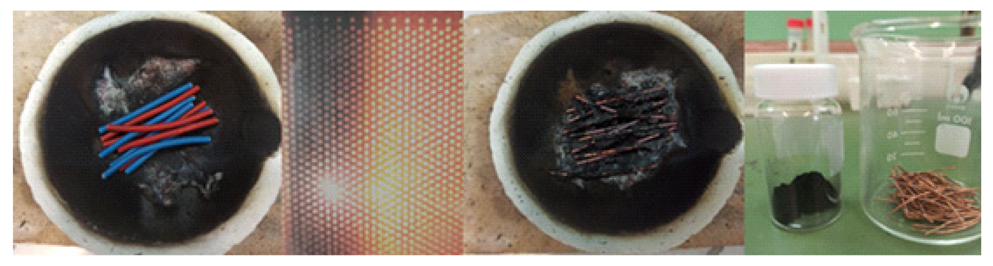
Figure 2.
XRD patterns of cable Cu wires before (black line) and after (green line) microwave treatment, as compared to crystalline copper.
Figure 2.
XRD patterns of cable Cu wires before (black line) and after (green line) microwave treatment, as compared to crystalline copper.
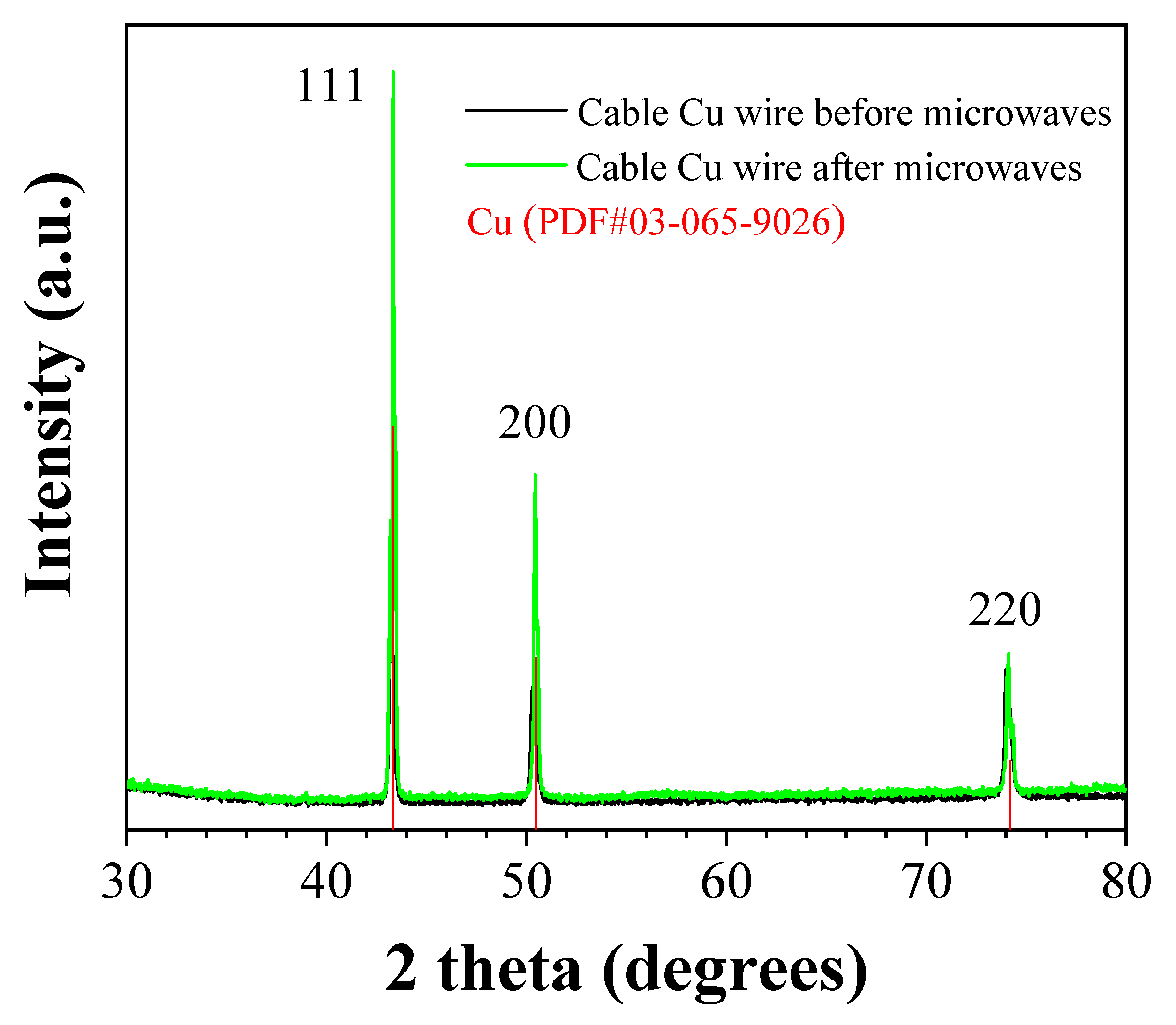
Figure 3.
XRD pattern of the derived carbon.
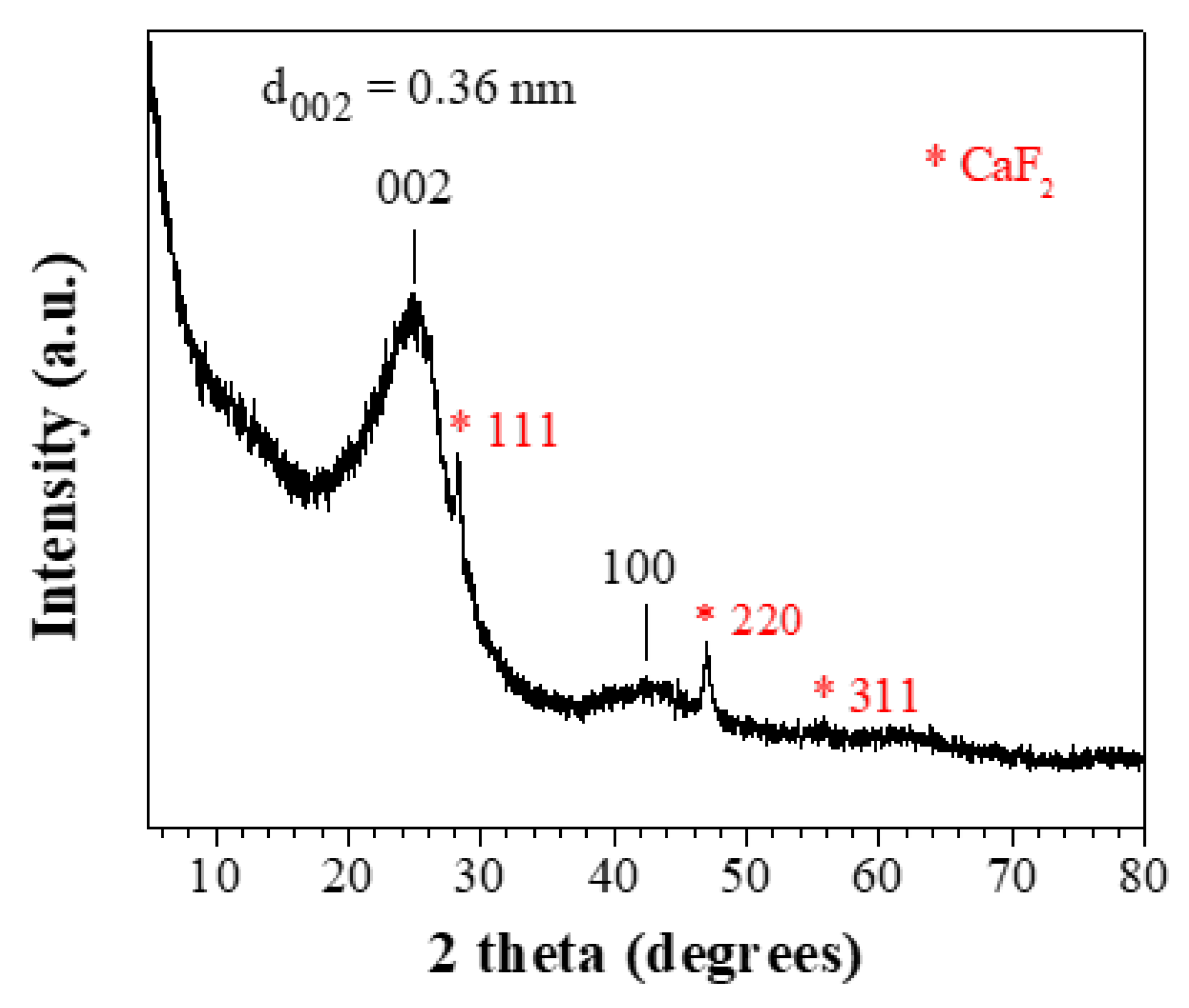
Figure 4.
Raman spectrum of the derived carbon.
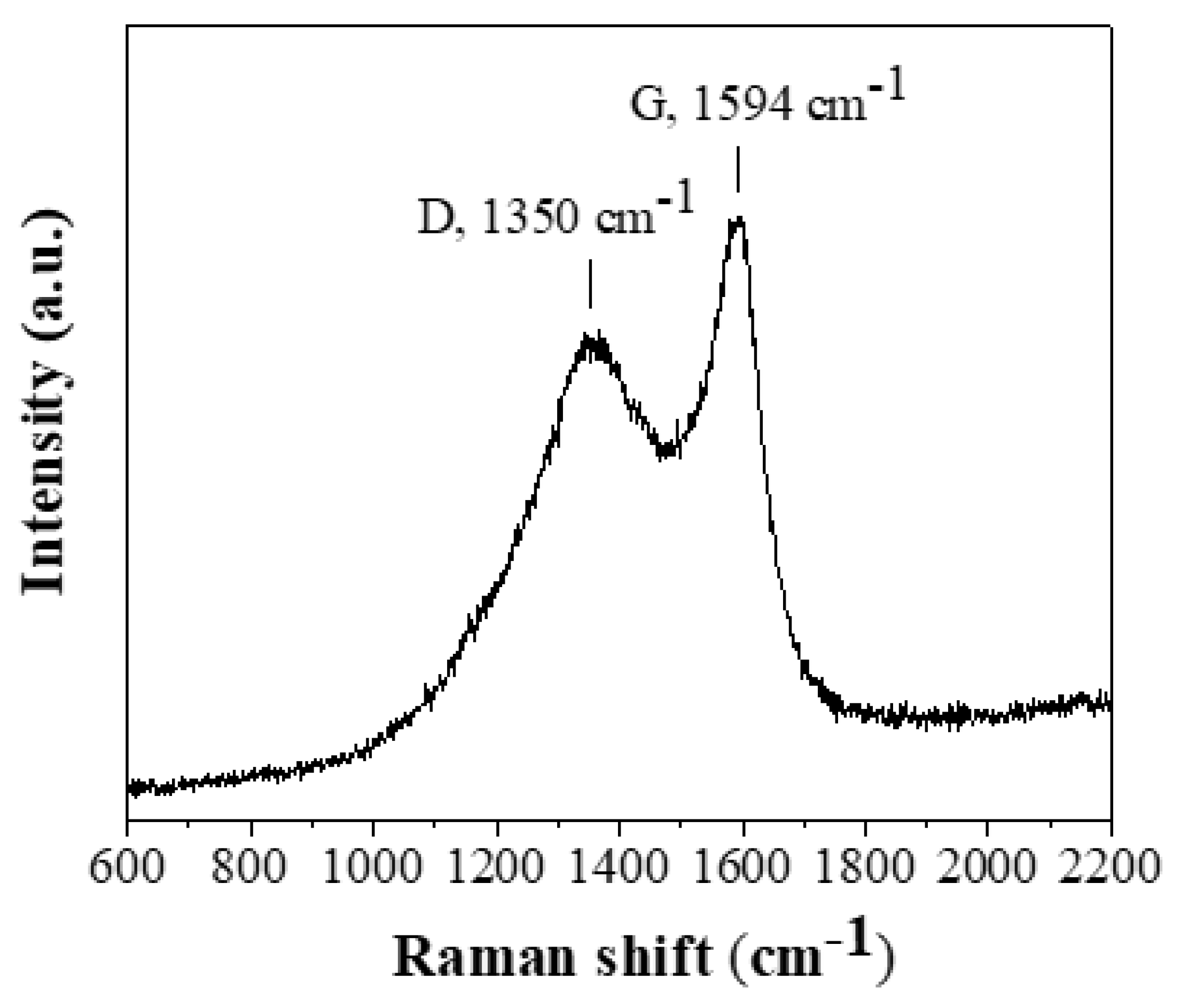
Figure 5.
XPS survey (left) and high resolution Cu2p (right) spectra of cable Cu wires before (black lines) and after (blue lines) microwave treatment.
Figure 5.
XPS survey (left) and high resolution Cu2p (right) spectra of cable Cu wires before (black lines) and after (blue lines) microwave treatment.
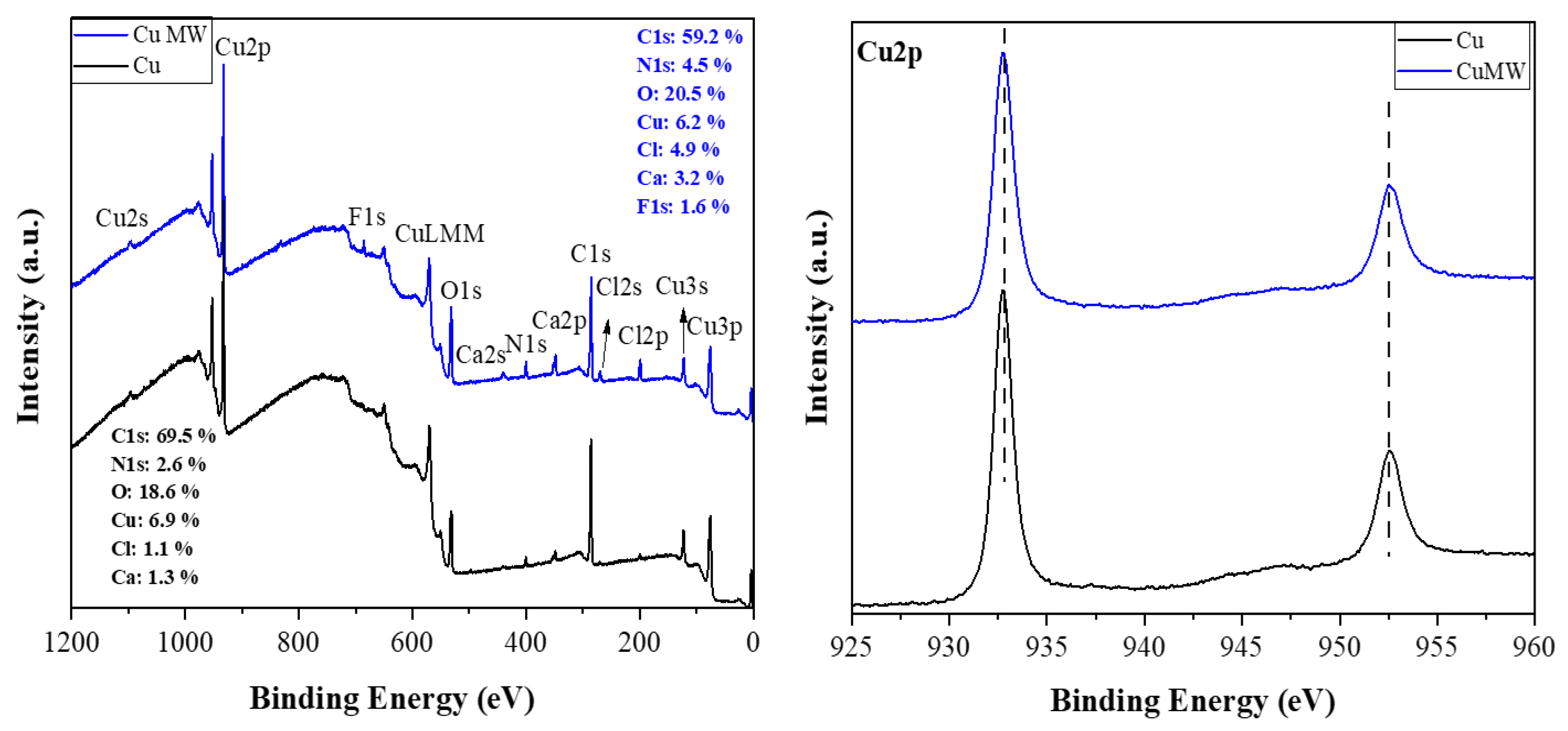
Figure 6.
XPS survey spectrum (a) and deconvoluted high-resolution spectrum of C1s region (b) of the derived carbon.
Figure 6.
XPS survey spectrum (a) and deconvoluted high-resolution spectrum of C1s region (b) of the derived carbon.
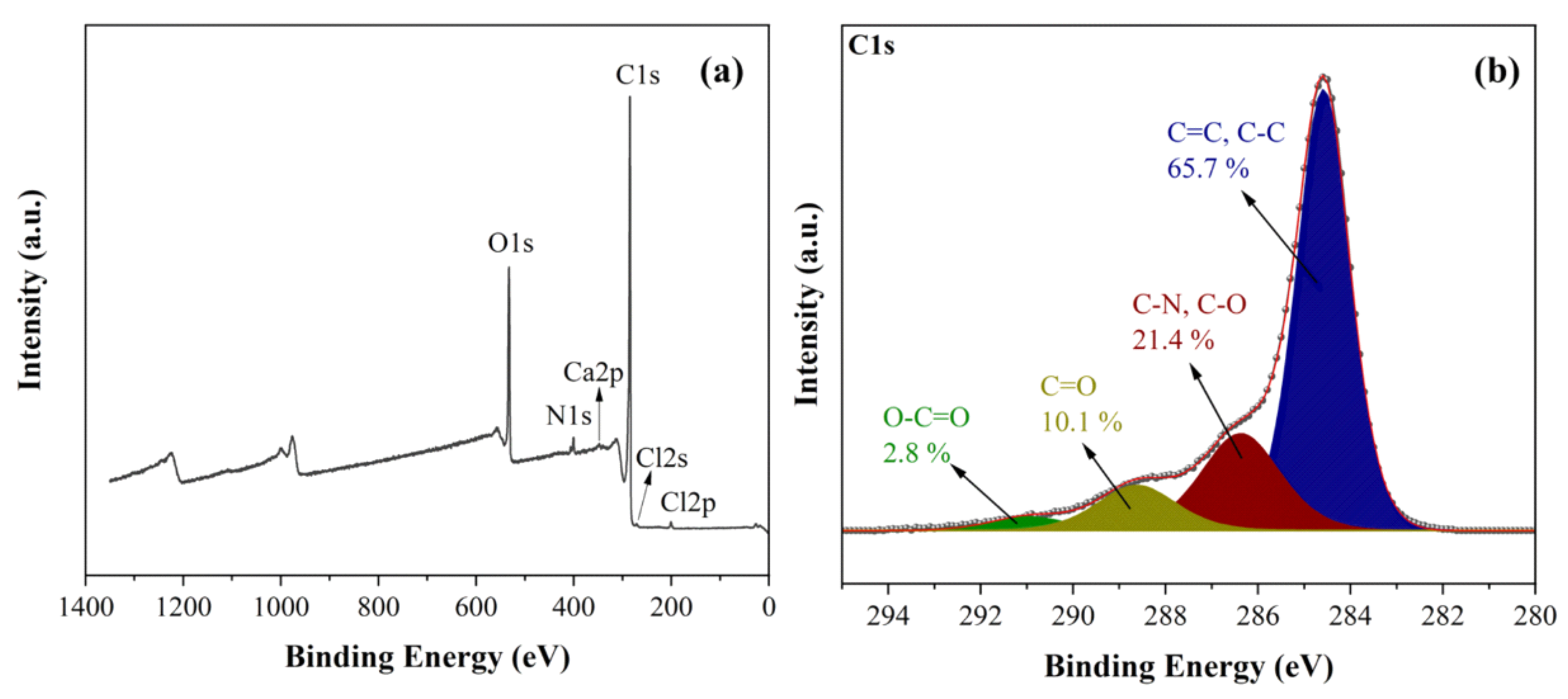
Figure 7.
Representative SEM images of cable Cu wires before (top) and after (bottom) microwave treatment under same magnification (scale bar 200 nm).
Figure 7.
Representative SEM images of cable Cu wires before (top) and after (bottom) microwave treatment under same magnification (scale bar 200 nm).
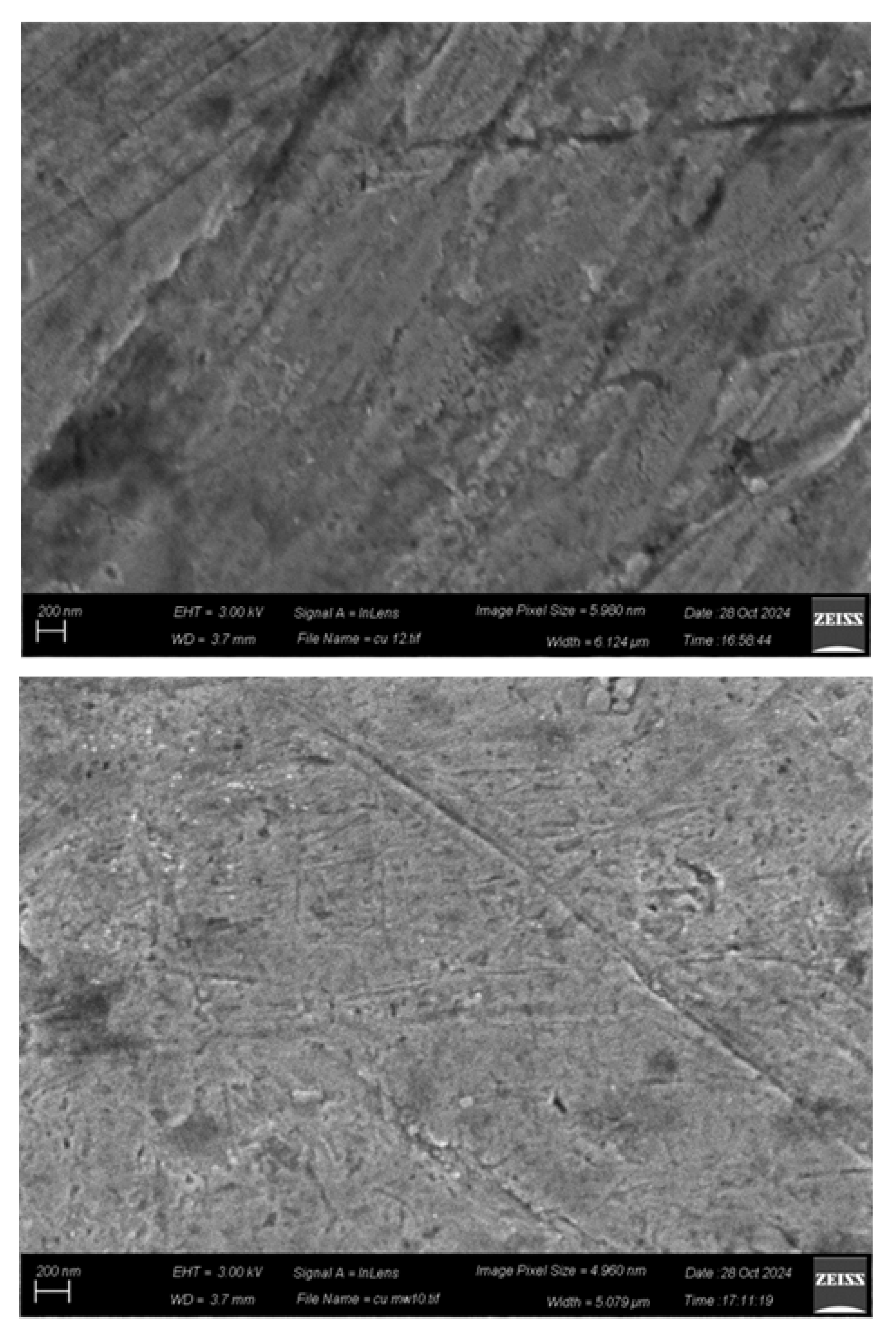
Figure 8.
Representative SEM images (top) and selected area C/O chemical mapping (bottom) of the derived carbon. Carbon and oxygen were chosen to represent the sample's major components.
Figure 8.
Representative SEM images (top) and selected area C/O chemical mapping (bottom) of the derived carbon. Carbon and oxygen were chosen to represent the sample's major components.
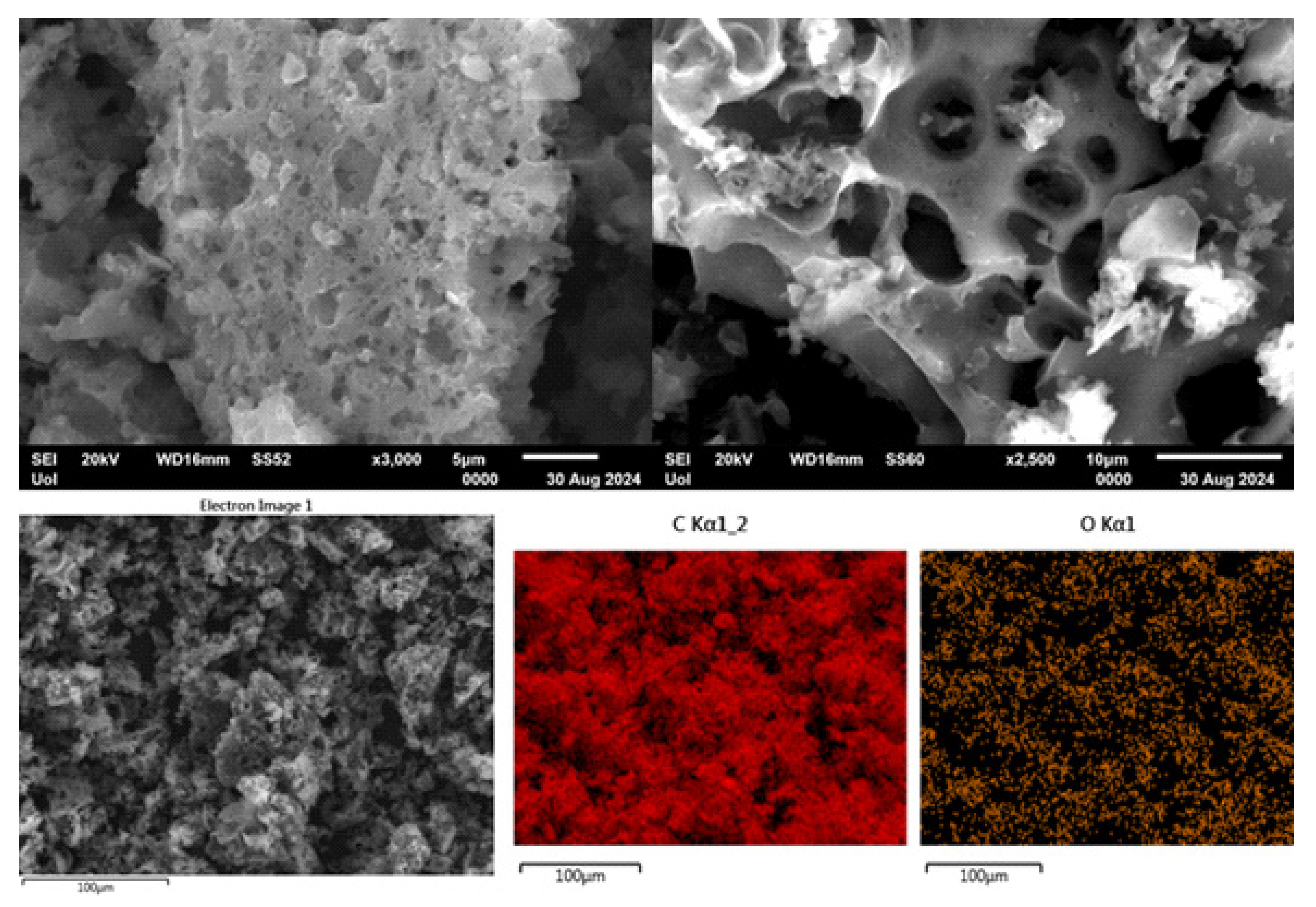
Figure 9.
Representative TEM images (a-d) of the derived carbon.
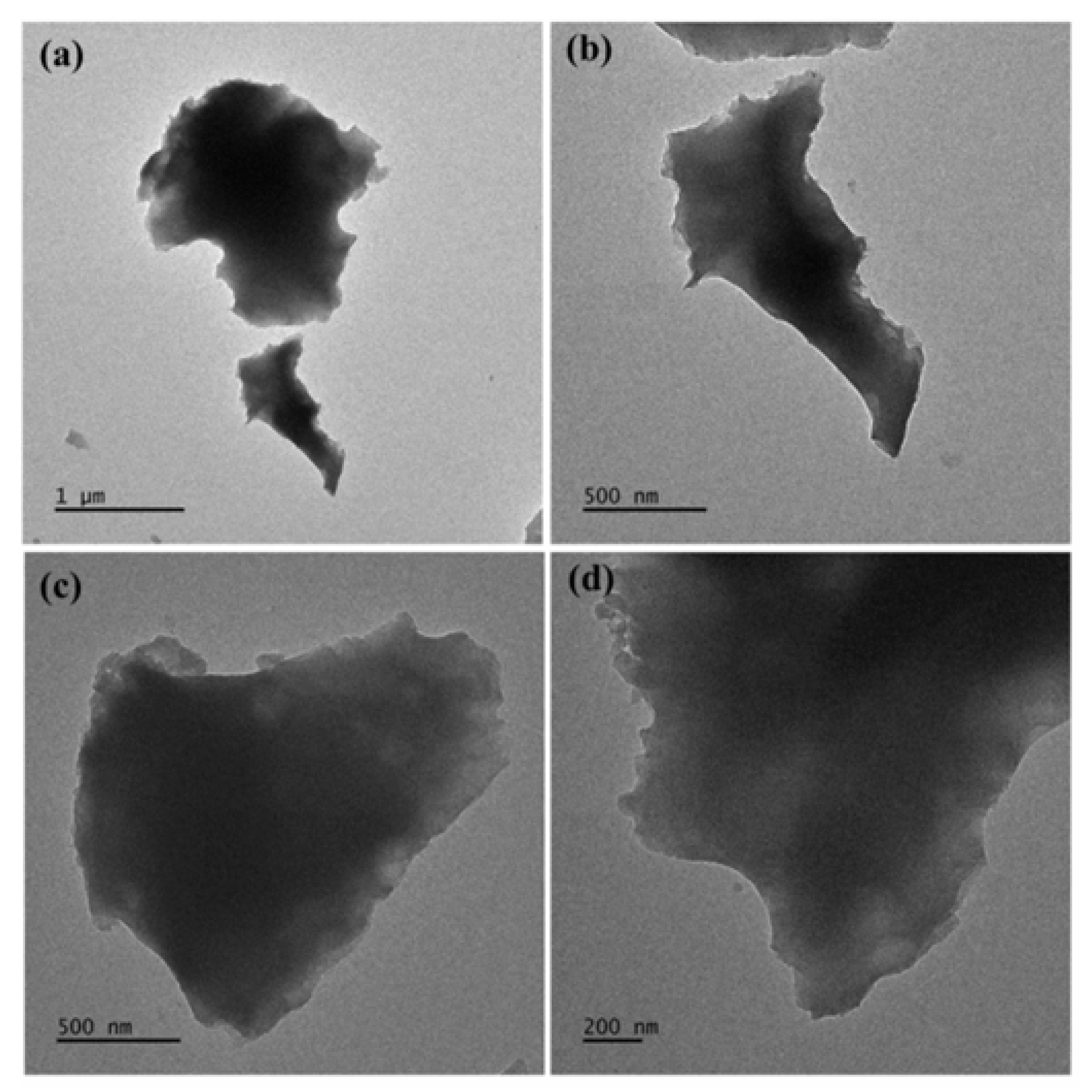
Figure 10.
(a) Representative height profile image derived by AFM of selected carbon nanosheet. (b) Statistical analysis histogram of thickness of randomly selected sheets.
Figure 10.
(a) Representative height profile image derived by AFM of selected carbon nanosheet. (b) Statistical analysis histogram of thickness of randomly selected sheets.
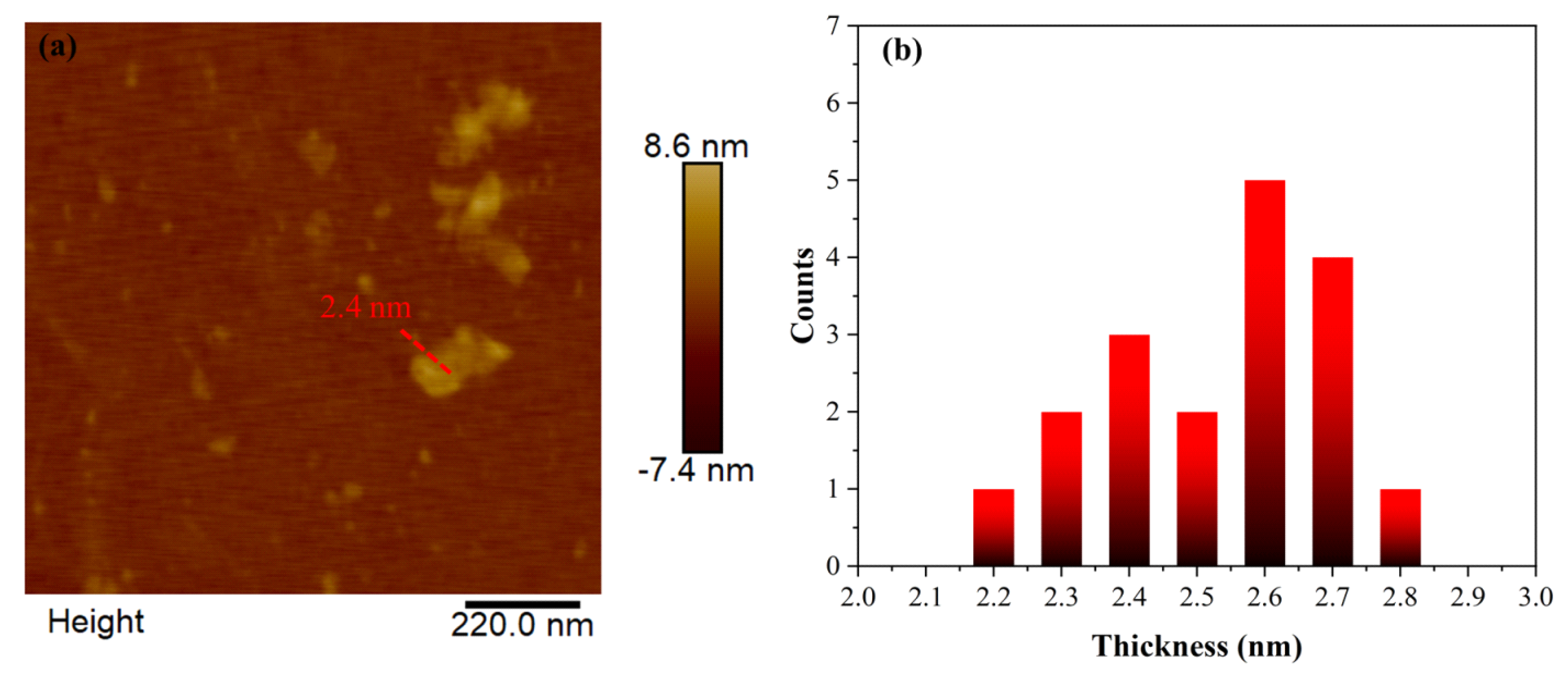
Figure 11.
N2 adsorption-desorption experimental hysteresis loop and CPSM simulation (a), BJH pore volume distribution, desorption branch (b), CPSM pore volume distribution (c), and DFT pore volume distribution (d).
Figure 11.
N2 adsorption-desorption experimental hysteresis loop and CPSM simulation (a), BJH pore volume distribution, desorption branch (b), CPSM pore volume distribution (c), and DFT pore volume distribution (d).
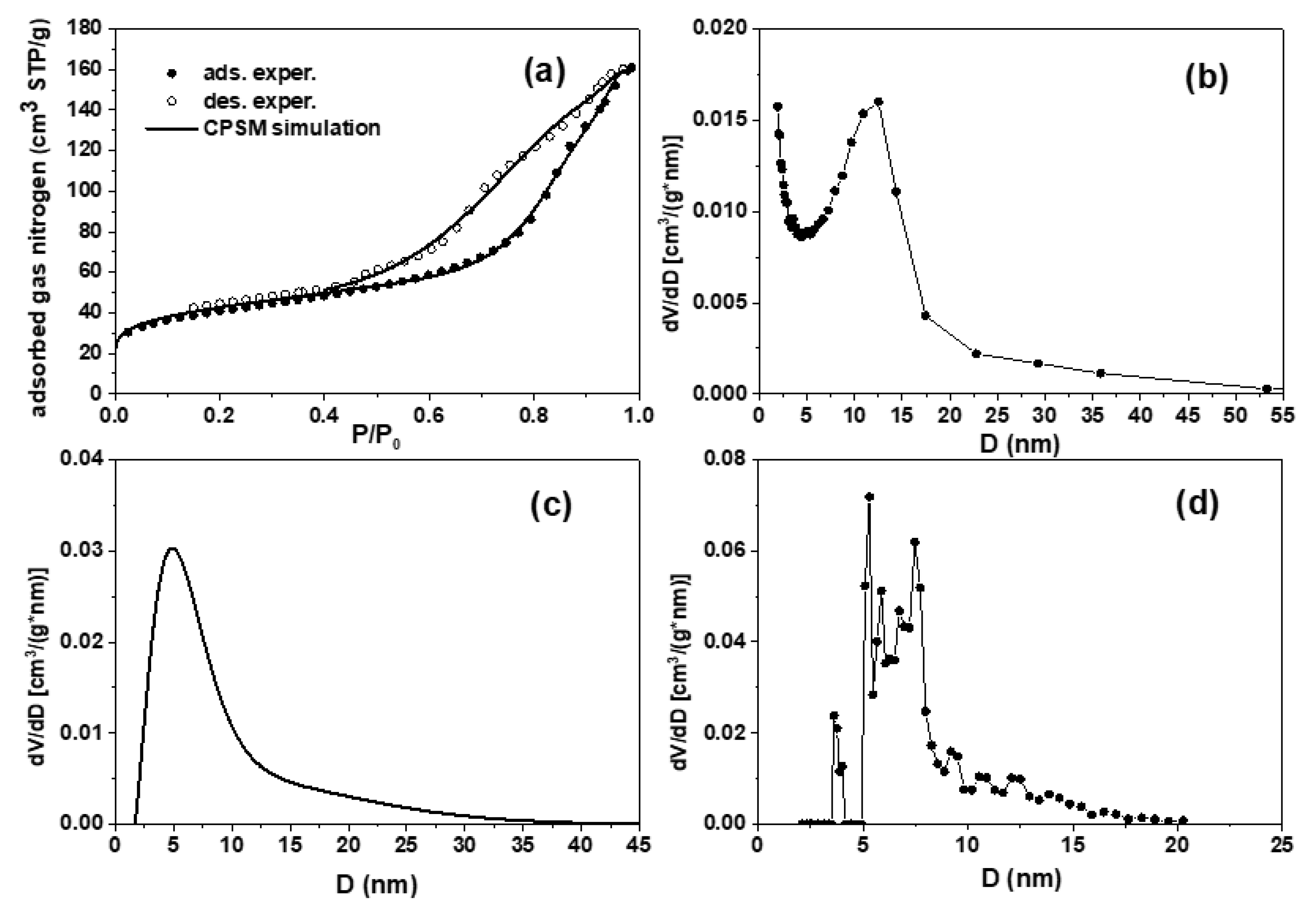
Figure 12.
XRD pattern of cable Cu wire after heat treatment of the cable at 500 °C in air.
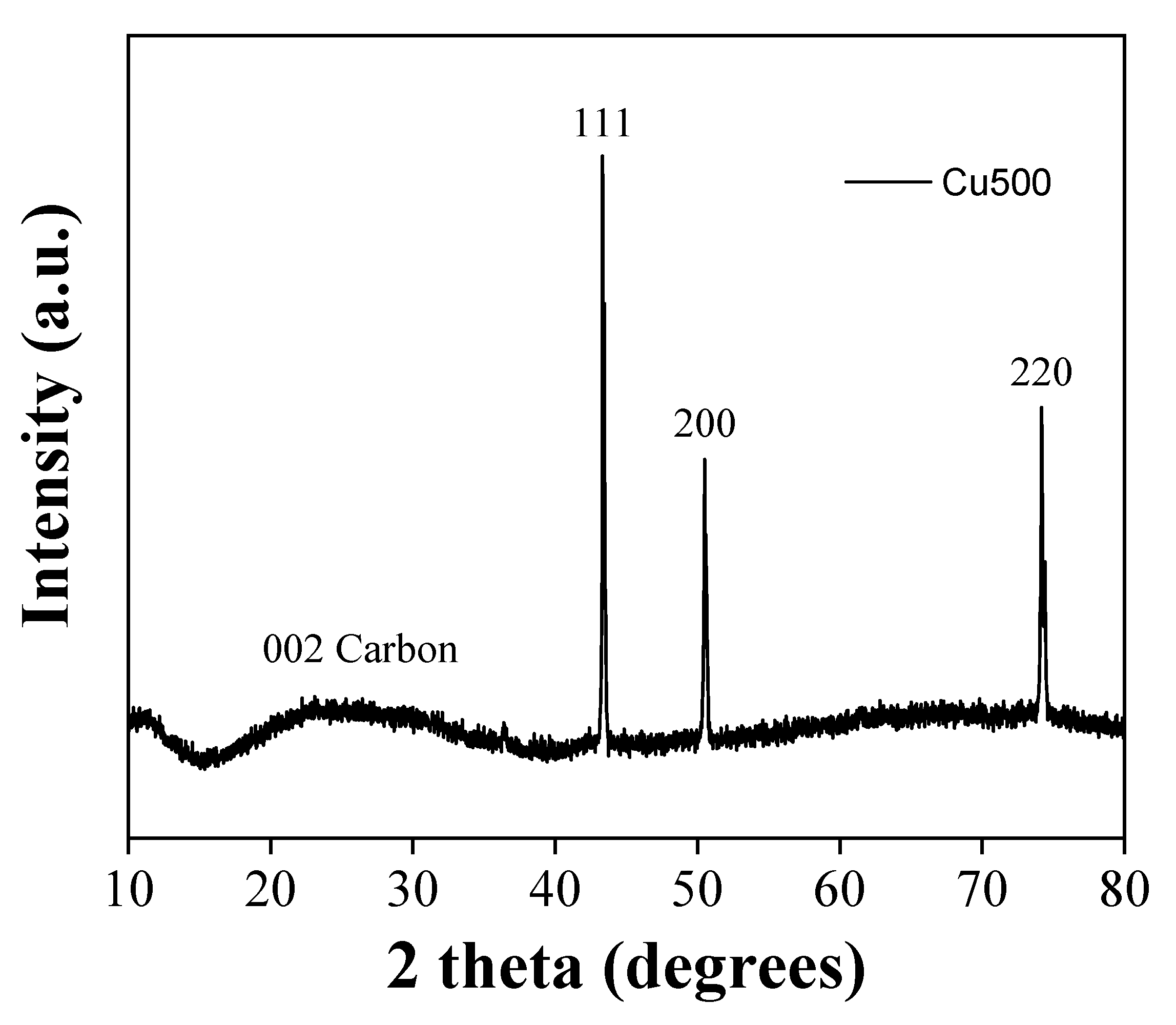
Figure 13.
XPS survey spectrum of cable Cu wire after heat treatment of the cable at 500 °C in air. The spectrum shows an increased carbon and oxygen content on the metal wire surface.
Figure 13.
XPS survey spectrum of cable Cu wire after heat treatment of the cable at 500 °C in air. The spectrum shows an increased carbon and oxygen content on the metal wire surface.
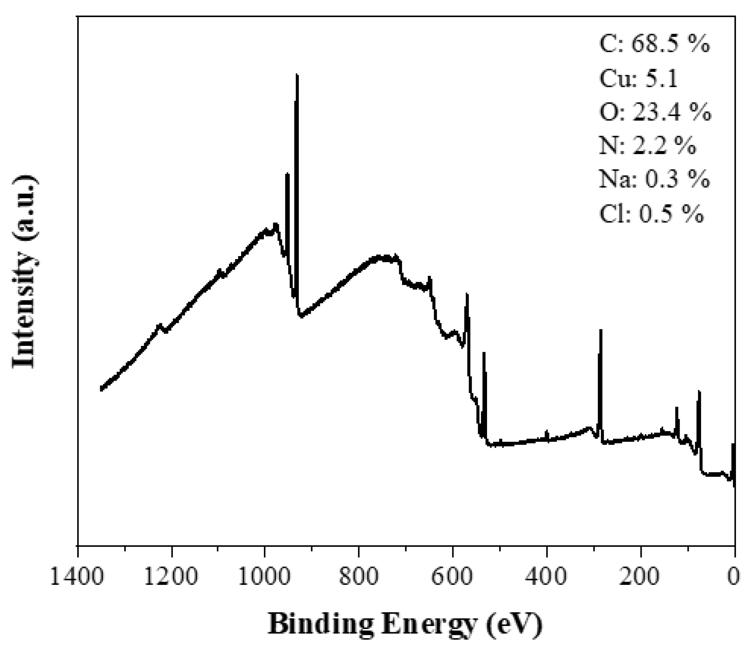
Figure 14.
Representative SEM image of cable Cu wire after heat treatment of the cable at 500 °C in air. The image shows that the metal wire surface is stained with carbon particles.
Figure 14.
Representative SEM image of cable Cu wire after heat treatment of the cable at 500 °C in air. The image shows that the metal wire surface is stained with carbon particles.
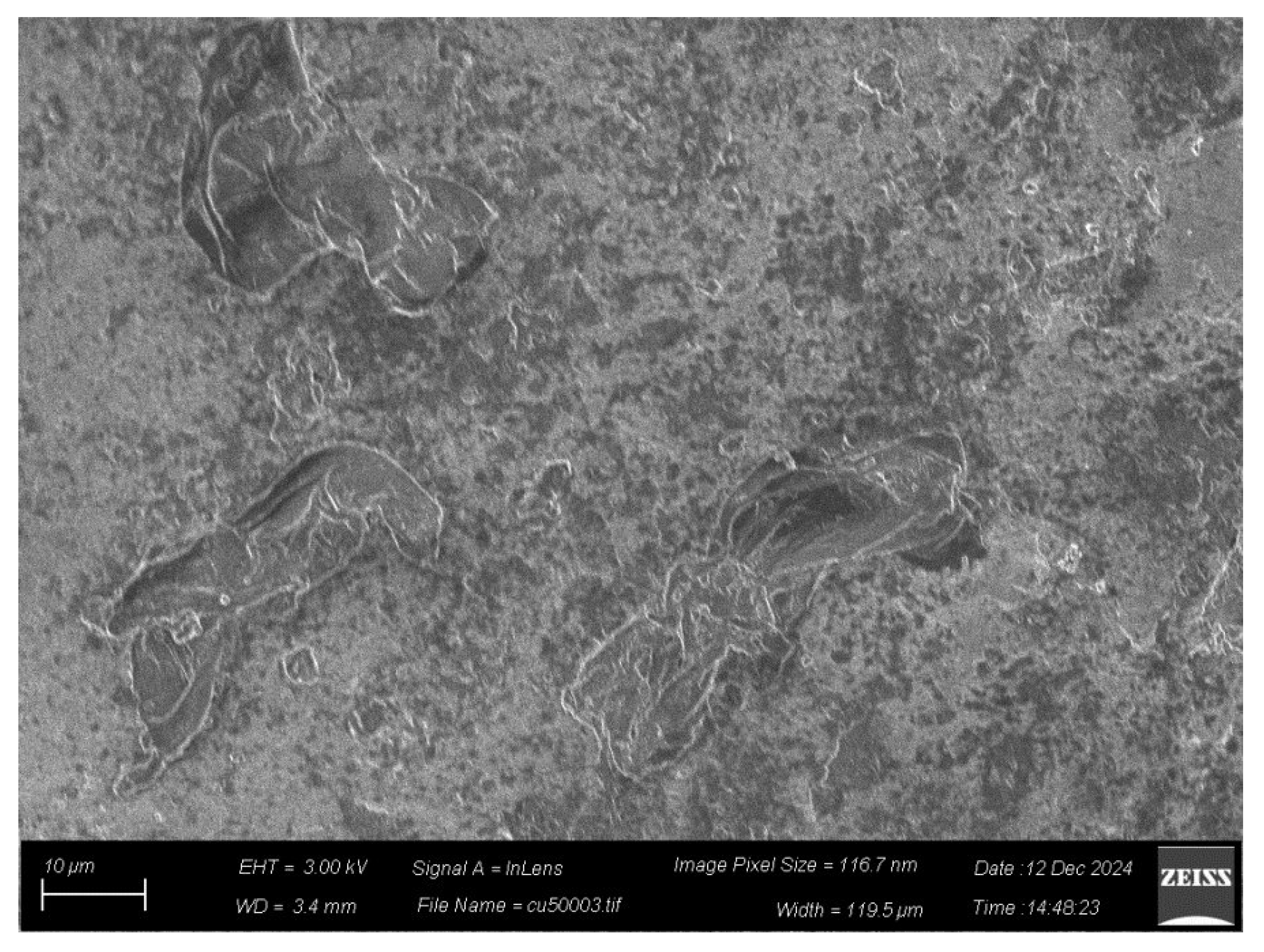
Figure 15.
XRD pattern of carbon derived from heat treatment of the cable at 500 °C in air.
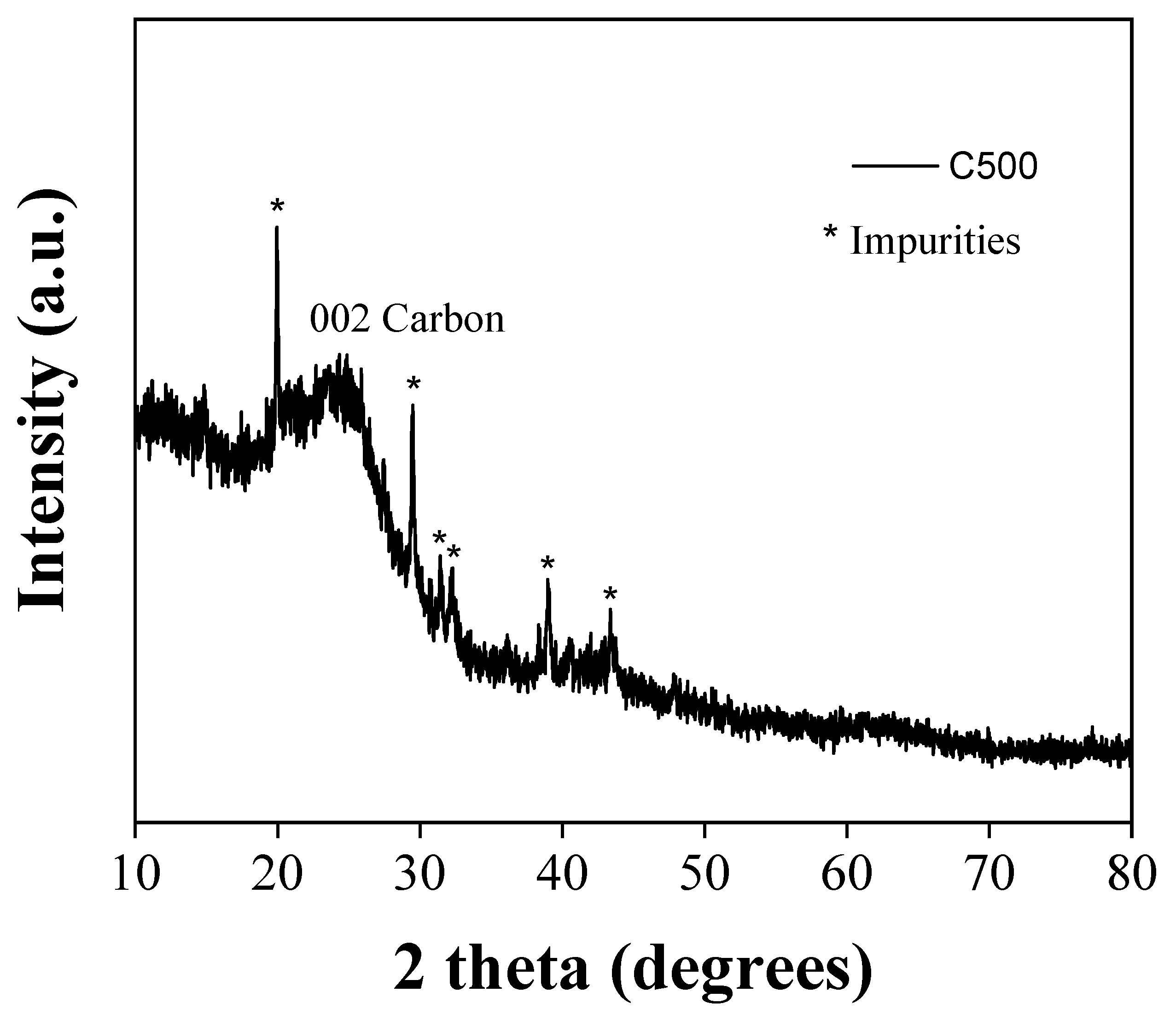
Figure 16.
Deconvoluted high-resolution C1s XPS spectrum of carbon derived from heat treatment of the cable at 500 °C in air.
Figure 16.
Deconvoluted high-resolution C1s XPS spectrum of carbon derived from heat treatment of the cable at 500 °C in air.
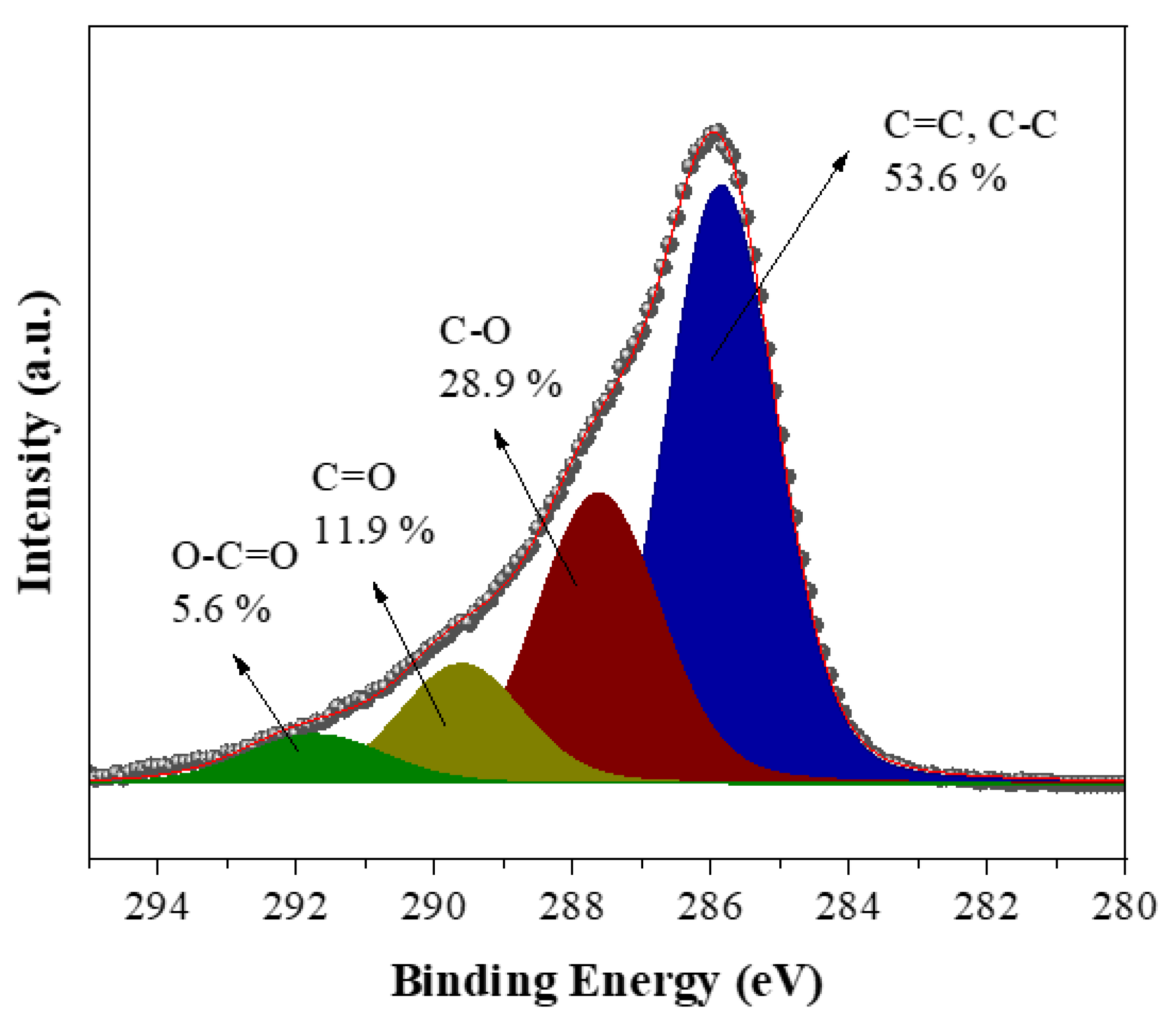
Figure 17.
Representative SEM image of carbon derived from heat treatment of the cable at 500 °C in air.
Figure 17.
Representative SEM image of carbon derived from heat treatment of the cable at 500 °C in air.
Disclaimer/Publisher’s Note: The statements, opinions and data contained in all publications are solely those of the individual author(s) and contributor(s) and not of MDPI and/or the editor(s). MDPI and/or the editor(s) disclaim responsibility for any injury to people or property resulting from any ideas, methods, instructions or products referred to in the content. |
© 2025 by the authors. Licensee MDPI, Basel, Switzerland. This article is an open access article distributed under the terms and conditions of the Creative Commons Attribution (CC BY) license (http://creativecommons.org/licenses/by/4.0/).
Copyright: This open access article is published under a Creative Commons CC BY 4.0 license, which permit the free download, distribution, and reuse, provided that the author and preprint are cited in any reuse.


