Submitted:
28 February 2025
Posted:
28 February 2025
You are already at the latest version
Abstract
With the rapid advancement of deep learning and computer vision technologies, image recognition and robotic arms have become essential in various fields, such as real-time recognition in smartphones and autonomous driving. These technologies not only improve efficiency but also reduce reliance on human labor. To help students develop practical skills, we designed a teaching module that integrates the YOLO algorithm, robotic arm technology, and local crop recognition. This system enables a robotic arm to automatically classify fruits upon detection and precisely move them to designated locations. Through hands-on practice, students gain experience in applying image recognition and robotic arm technology, fostering essential skills for smart agriculture. By combining YOLO with robotic automation, students can engage in real-world fruit classification and sorting, strengthening their understanding of AI-driven agricultural solutions. This approach not only enhances their technical proficiency but also lays a strong foundation for future applications in automation and smart industries.
Keywords:
Fruit Recognition
; Robotic Arm
; YOLOv4
; Deep Learning
1. Introduction
1.1. Research Motivation and Objectives
In recent years, machine vision and robotics technologies have rapidly developed, particularly with advancements in deep learning and object detection techniques, opening new possibilities for automation. As a crucial component of automated tasks, robotic arms are capable of precise movements and operations. Therefore, relevant knowledge has become an essential tool for the future. To allow students to gain a deeper understanding and hands-on experience, we plan to develop an auxiliary teaching system.
The YOLO algorithm has been widely praised in the field of computer vision due to its multiple advantages. First, its highly efficient real-time performance makes it the preferred choice for various real-time applications, such as autonomous driving and surveillance systems. Second, it employs an end-to-end training method, directly mapping raw images to prediction results, which simplifies the process and improves efficiency. Furthermore, YOLO uses a single network structure, treating object detection as a regression problem, making the model simple and easy to understand. It also effectively handles multi-scale object detection issues by using feature maps at different scales. Most importantly, despite maintaining high processing speed, YOLO still achieves excellent detection accuracy, making it a milestone in object detection and widely applied in various practical applications.
Based on this, we have combined the YOLO algorithm, robotic arms, and local thriving agriculture to develop a fruit recognition and grasping system, enabling the robotic arm to automatically identify and grasp different types of fruits. This will help students deeply understand the relevant knowledge and gain practical experience.
Through this practical project, students will not only learn object detection and robotic control techniques but also enhance their problem-solving skills and innovative thinking. This combination of theory and practice will lay a solid foundation for their future careers and increase their competitiveness. At the same time, the system's development process will foster teamwork and enhance communication and collaboration among students.
1.2. Literature Review and Related Research
We will consider using the YOLO algorithm for object detection and image recognition. In [1], the authors used a pre-trained YOLO architecture to detect affected pine trees in ultra-high-resolution images captured by drones, achieving an average accuracy of 91.82%. Similarly, in [2], the authors employed the YOLO framework to detect bark beetle infestation in Norway spruce trees, obtaining commendable mAP metrics and maintaining a certain processing capability even in medium-resource settings.
In education-related research, [11] combined robotic arms with multimedia animations to develop an interactive teaching material focused on mechatronic integration. The results showed that teaching materials that allow hands-on operations effectively increase learners' interest, and repeated practice strengthens their memory and understanding of the relevant knowledge.
With the development of YOLO networks, YOLO has become as accurate as some two-stage detection methods. The YOLO (You Only Look Once) algorithm was initially proposed by Joseph Redmon and colleagues. In 2016, they introduced the improved YOLOv1 algorithm, followed by YOLOv2 [4] and YOLOv3 [5]. With further contributions from researchers, in April 2020, the team led by Alexey Bochkovskiy proposed the YOLOv4 algorithm [6].
Compared to its earlier versions, YOLOv4 offers several significant advantages. Firstly, it improves object detection accuracy by introducing new feature extraction modules and enhanced training strategies, allowing the model to better capture subtle features in images and enhancing detection performance. Secondly, despite increasing the depth and complexity of the model, YOLOv4 maintains excellent processing speed, thanks to optimizations in the model structure and training algorithms. Additionally, YOLOv4 incorporates more data augmentation techniques and regularization methods during the training process, improving the model's generalization ability and making it more robust in different scenarios and lighting conditions. Overall, YOLOv4 shows significant improvements in accuracy, processing speed, generalization ability, and enhanced functionality. Therefore, this study will use the YOLOv4 algorithm for related research and improvements.
2. Hardware Architecture
2.1. Experimental Environment
As shown in Figure 1 and Figure 2, the experimental setup we designed includes a robotic arm, a camera, a fruit recognition area, and six designated areas for placing different fruits. Initially, we place a fruit in the recognition area, and the camera captures the image of the fruit. After recognition using the YOLOv4 algorithm, a command is sent to the robotic arm via serial communication to move to the specified position. The robotic arm is equipped with an air compressor to supply pressure to the gripper for fruit picking, and it subsequently places the fruit in the designated fruit placement area.
The robotic arm in this experiment is developed using the NVIDIA Jetson Nano. The Jetson Nano is a small, low-power embedded AI computing platform developed by NVIDIA, designed to provide powerful AI processing capabilities while maintaining a compact size and energy efficiency. It is a powerful, high-performance, and easy-to-develop-and-deploy embedded AI computing platform suitable for developing and implementing various AI applications.
The Arduino is used as the core control for the arm's movement algorithm, responsible for receiving control commands sent via serial communication. A 1080P 60FPS, 120-degree wide-angle camera is used as the receiver. The camera is positioned approximately 30 cm from the detected object and about 15 cm above the ground, with a detection angle of about 30 degrees downward.
2.2. Dynamics of the Robotic Arm
2.2.1. Subsubsection
The D-H method is a mathematical approach used to establish the kinematic model of a robotic arm, proposed by Jacques Denavit and Richard S. Hartenberg in 1955. Initially, the relative position between two joints required six parameters for representation, consisting of three translational and three rotational components. However, the D-H method simplifies this by describing the spatial relationship between two joints using only four parameters.
The four parameters in the D-H method are , , wheredenotes the -th joint of the robotic arm. The definitions of these parameters are as follows, as shown in Fi Figure 3:
- is the distance between point .
- is the angle of rotation from to , with counterclockwise rotation around being positive.
- is the distance between point and
- is the angle of rotation from to with counterclockwise rotation around being positive.
Using the D-H method, the transformation relationship from the joint coordinates of the -th axis to the joint coordinates of the -th axis can be represented by . . Here, . denotes the transformation matrix that converts the coordinates from the -th axis to the -th axis, as shown in equation (1).
Once the transformation matrices for each axis relative to the previous axis have been obtained, these matrices can be multiplied together to yield the transformation matrix from the base to the end effector.
3. Research Methods
3.1. YOLOv4[1]
As shown in Figure 4, the YOLOv4 framework can be broadly divided into the following components:
- Input: The input image.
- Backbone: The backbone network is utilized for preliminary feature extraction. YOLOv4 employs CSPDarknet53.
- Neck: This component integrates feature maps from various layers of the backbone, utilizing Spatial Pyramid Pooling (SPP) and Path Aggregation Network (PAN).
- Head: This part makes predictions based on the image features, generating predicted bounding boxes and class predictions, using the head architecture from YOLOv3.
The YOLOv4 development framework is illustrated in Figure 5, providing an overview of the system's overall architecture and detailing how each component contributes to the object detection process.
3.2. Dataset [8]
Commonly used training datasets include PASCAL VOC and COCO. This experiment utilizes the VOC training dataset architecture, as shown in Figure 6.
PASCAL VOC is one of the most widely used datasets, containing 20 different object classes, such as person, car, airplane, dog, and cat. Each image is accompanied by an XML annotation file that describes the class, location, and size of each object within the image. The VOC dataset is typically divided into a training set, validation set, and test set for model training, validation, and evaluation.
In Figure 9, the annotated images and their corresponding files are organized and prepared. A program is then utilized to divide the dataset into training and test sets. Next, navigate to the ./darknet/cfg/ directory is required to modify yolov4-tiny-custom.cfg. A copy of this file should be made and renamed to obj.cfg, followed by adjustments to the filters and classes settings, as indicated in Figure 10, where filters = 3 × (classes + 5). The pre-trained YOLOv4 model should then be downloaded into the Darknet directory, as shown in Figure 11. Finally, the command to begin training can be executed. The command format for training is ./darknet detector train data_path cfg_path yolov4-tiny.conv.29.
Once the command is entered, the training process will commence. This involves using the Darknet framework to train the object detection model, including configuring training parameters, selecting the model architecture, and conducting the model training. The goal is for the model to effectively learn to identify objects within images. At the conclusion of this process, a trained object detection model will be produced. After exporting the model in the specified format, performance and accuracy can be evaluated using the test set, with any necessary adjustments and optimizations made thereafter.
3.4. Coordinate Transformation
After completing the recognition process, the YOLO model outputs a series of bounding box coordinates relative to the image size, along with related information. This includes the relative position of the box center, the width and height of the box, and the confidence score. Since these coordinates are given as proportional values, they need to be converted into pixel coordinates. By multiplying the relative bounding box coordinates by the image width and height, the pixel coordinates of the bounding box can be obtained, including the center point and the actual width and height of the box. This serves as the foundation for further spatial coordinate calculations.
Next, using the camera intrinsic matrix K and the depth value Z, the pixel coordinates are transformed into three-dimensional coordinates in the camera coordinate system. The intrinsic matrix K defines the optical characteristics of the camera, including focal length and image center position. as shown in equation (2).
Each bounding box's center point can be mapped to the camera coordinate system, obtaining its three-dimensional spatial position in the camera frame. The key to this step lies in the accuracy of the depth value, as the depth value Z directly affects the precision of the target's spatial localization.
Finally, to enable the robotic arm to achieve precise positioning, the three-dimensional coordinates in the camera coordinate system need to be transformed into the world coordinate system. This transformation can be achieved using the rotation matrix R and the translation vector T, following the equation (3):
where:
Pworld represents the three-dimensional coordinates of the target in the world coordinate system.
The rotation matrix RRR describes the orientation of the camera relative to the world coordinate system, while the translation vector TTT defines the camera's position in the world coordinate system. After completing these transformations, the precise position of the object in the world coordinate system can be obtained and transmitted to the robotic arm to perform defect repairs or other operational tasks.
This process ensures accuracy and efficiency from recognition to localization, meeting the requirements of real-world applications.
4. Experiment Research and Results
4.1. Experiment Process
As shown in Figure 12, students are instructed to place a type of fruit in front of the camera within the recognition area. At this point, the robotic arm operates automatically, grasping the fruit, placing it in the designated fruit placement area, and returning to its initial position.
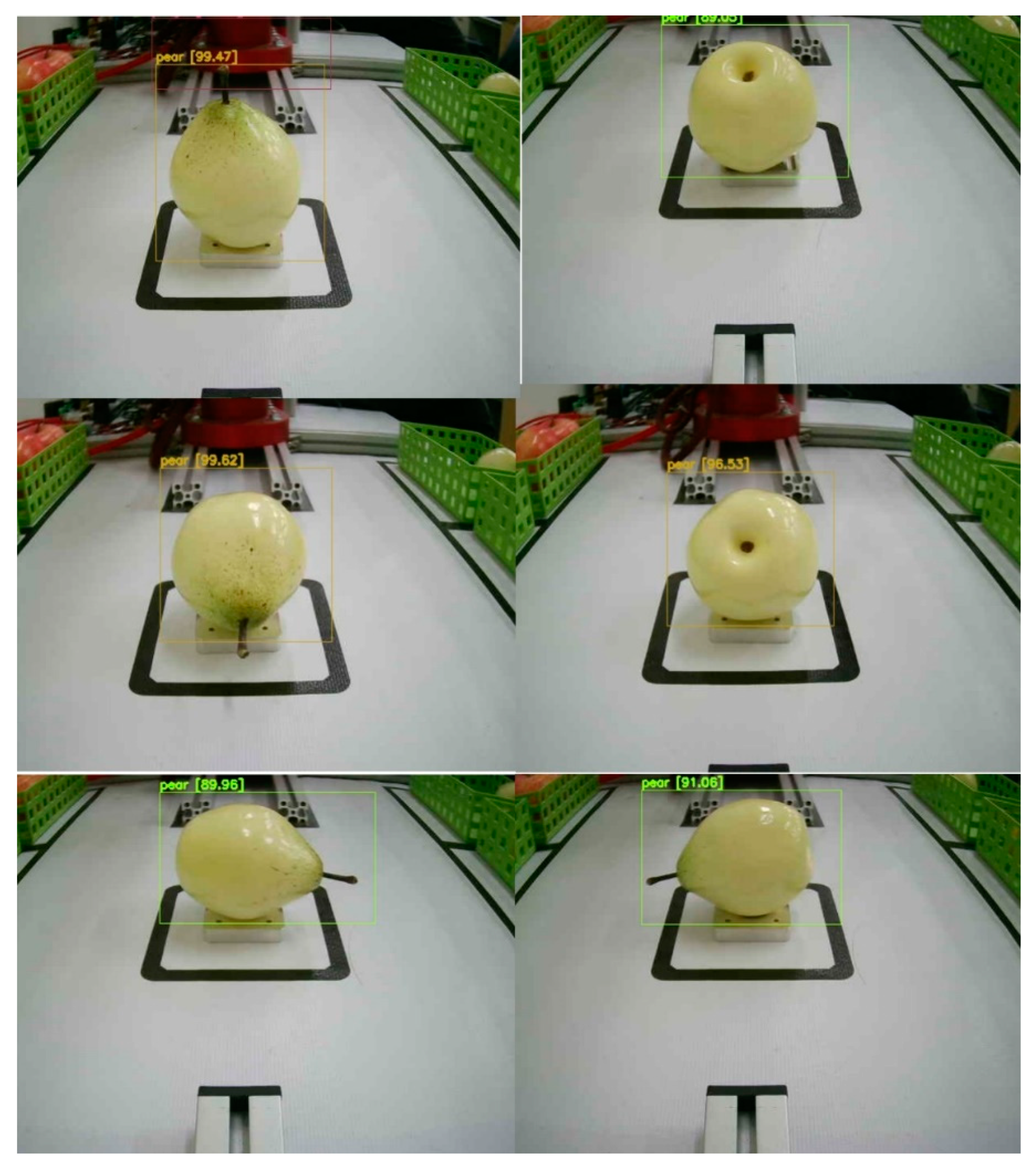
Each type of fruit is placed at six different angles (as shown in Figure 13), and the robotic arm returns it to its original position after each placement. This process is repeated for each fruit type, with the confidence level for detecting each fruit at different angles recorded during the trials.
4.2. Experiment Results
The results are summarized in Table 4.1, which displays the performance of the robotic arm in handling various fruits positioned at different angles. Based on the test results, the robotic arm successfully identified the fruits and returned them to their original positions in the vast majority of cases. However, when the mangosteen was facing backward, the confidence value of the predicted bounding box was relatively low, resulting in the robotic arm's failure to place it back correctly. This situation serves as a discussion point for students to explore the reasons behind this phenomenon and share potential solutions, thereby enhancing their understanding of algorithm-related concepts.

Table 4.1.
The performance of the robotic arm on various fruits and angles.
| Fruit Orientation | Up | Down | Left | Right | Front | Back |
| Pear | 99.47 | 96.53 | 91.06 | 89.96 | 99.62 | 89.05 |
| Lemon | 95.87 | 89.45 | 91.48 | 90.19 | 96.64 | 88.74 |
| Orange | 81.54 | 83.32 | 81.52 | 85.39 | 91.47 | 80.61 |
| Apple | 99.73 | 92.54 | 92.64 | 94.03 | 96.32 | 91.45 |
| Wax apple | 80.77 | 85.62 | 81.47 | 90.72 | 80.55 | |
| Mangosteen | 96.22 | 91.20 | 99.64 | 92.56 | 98.71 | 70.51 |
5. Conclusion and Future Prospects
According to the test results, this experiment successfully identified various fruits and completed classifications accurately in the vast majority of cases. However, when the mangosteen was facing backward toward the robotic arm, the confidence value of the predicted bounding box decreased, resulting in the robotic arm's failure to accurately grasp and return it to its original position. This phenomenon indicates that the system may experience performance degradation when dealing with certain angles or variations in the appearance of fruits, reflecting the limitations of integrating image recognition with robotic arms in practical applications.
In the future, students can be encouraged to explore and discuss the reasons behind this phenomenon, such as the effects of lighting, angles, or surface features of objects on algorithm predictions. Additionally, motivation should be provided to explore potential solutions, such as training with more data, optimizing the parameters of the YOLO algorithm, or introducing advanced deep learning techniques. Moreover, students can learn to leverage technology to solve real-world problems, further enhancing their understanding of machine vision and robotic arm systems, thus laying a solid foundation for future applications in smart industries.
The aim is to expand the system's application scope, teaching students how to apply it to various scenarios and fruit recognition tasks. Beyond common fruits, students will investigate the recognition of fruits with various shapes and sizes, including soft or irregularly shaped fruits, to understand the impact of different features on recognition. Throughout the teaching process, students will learn to expand databases and adjust the YOLO algorithm to optimize recognition accuracy while improving the robotic arm's control to handle different fruits, thereby enhancing the flexibility of the automation system. These skills will assist in grasping deep learning technologies and applying them to smart agriculture and other fields.
References
- Safonova, A.; Hamad, Y.; Alekhina, A.; Kaplun, D. Detection of Norway Spruce Trees (Picea Abies) Infested by Bark Beetle in UAV Images Using YOLOs Architectures. IEEE Access 2022, 10, 10384–10392. [Google Scholar]
- Wang, L.; Zhou, K.; Chu, A.; Wang, G.; Wang, L. An Improved Light-Weight Traffic Sign Recognition Algorithm Based on YOLOv4-Tiny. IEEE Access 2021, 9, 124963–124971. [Google Scholar] [CrossRef]
- Redmon, J.; Divvala, S.; Girshick, R.; Farhadi, A. You Only Look Once: Unified, Real-Time Object Detection. In Proceedings of the 2016 IEEE Conference on Computer Vision and Pattern Recognition (CVPR), Las Vegas, NV, USA; 2016; pp. 779–788. [Google Scholar] [CrossRef]
- Redmon, J.; Farhadi, A. YOLO9000: Better faster stronger. In Proceedings of the Proc. IEEE Conf. Comput. Vis. Pattern Recognit. (CVPR); 2017; pp. 6517–6525. [Google Scholar]
- Ehsani, K.; Bagherinezhad, H.; Redmon, J.; Mottaghi, R.; Farhadi, A. Who let the dogs out? In Modeling dog behavior from visual data. In Proceedings of the Proc. IEEE/CVF Conf. Comput. Vis. Pattern Recognit; 2018; pp. 4051–4060. [Google Scholar]
- Bochkovskiy, A.; Wang, C.-Y.; Mark Liao, H.-Y. YOLOv4: Optimal speed and accuracy of object detection. arXiv 2020, arXiv:2004.10934. [Google Scholar]
- Han, G.-J.; Wang, R.-J.; Yuan, Q.-W.; Li, S.-D. Detection of Bird Nests on Transmission Towers in Aerial Images Based on Improved YOLOv5s. Machines 2023. [Google Scholar] [CrossRef]
- Wang, Y.-S. Adaptive Inverse Dynamics Motion Control with Image Based Visual Servoing for UR5 Manipulator. Master Thesis, National Dong Hwa University, Hualien, Taiwan, 2020. [Google Scholar]
- Lin, S.-C. Automated Garbage Classification and Retrieval System based on YOLOv4-tiny and Depth Image Information. Master Thesis, Feng Chia University, Taichung, Taiwan, 2023. [Google Scholar]
- Chiu, C.-F. A Research of Motorcycle Helmet Recognition Using Mask-RCNN and Yolov4 Model. Master Thesis, National Yunlin University of Science and Technology, Yunlin, Taiwan, 2023. [Google Scholar]
- Chen, W.-X.; Liao, J.-R.; Chen, A.-C.; Kou, P.-Y.; Ting, Y.-L. Combining Physical Robert Arm and Virtual Multimedia Animation with Electromechanical Integration Materials. In Proceedings of the 19th Conference on Research and Development in Science Education 2023 and the 12th Conference on Engineering, Technology, and STEM Education 2023; 2023; pp. 1037–1059. [Google Scholar]
Figure 1.
Schematic diagram of the experimental environment.
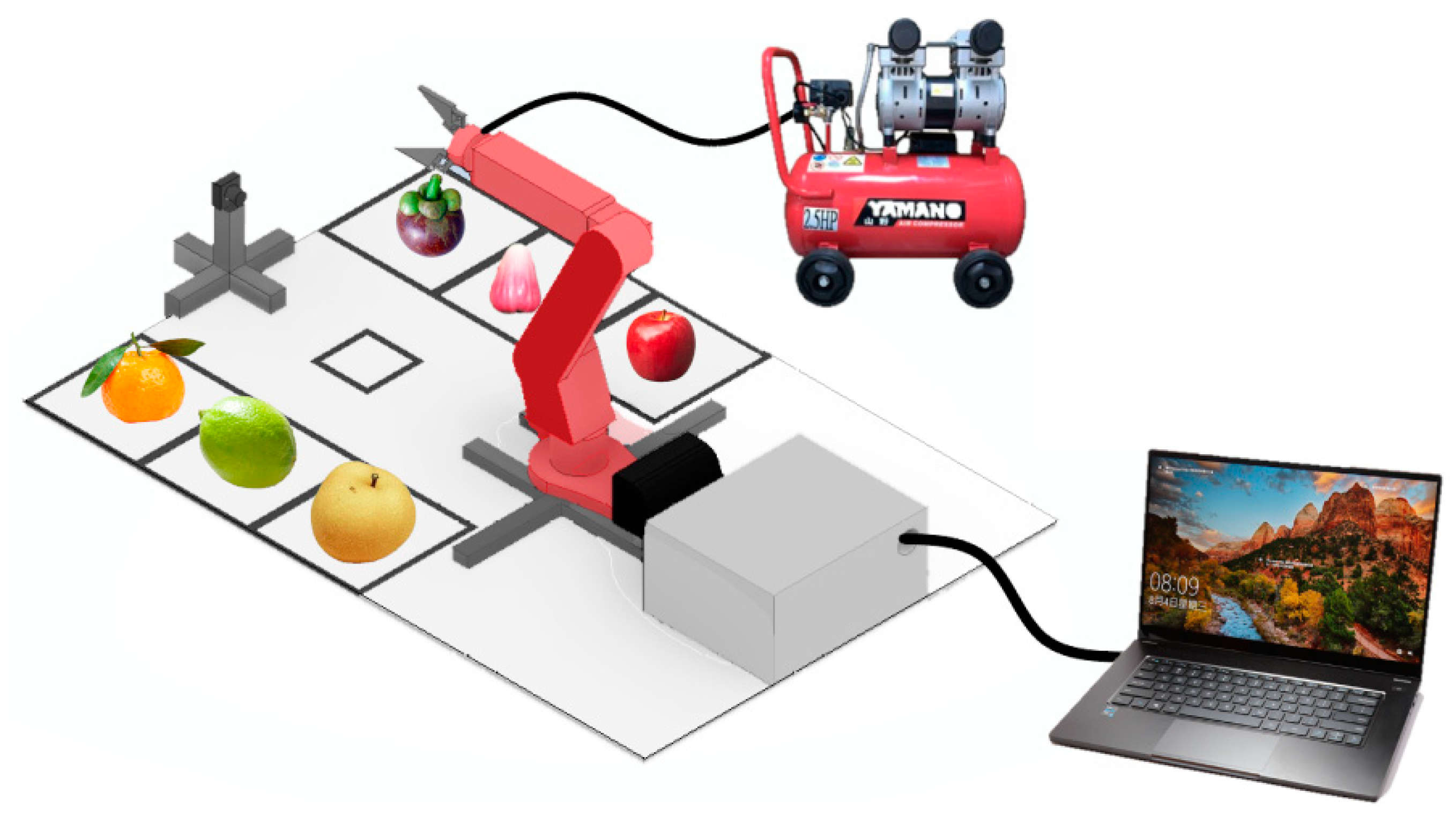
Figure 2.
Actual photo of teaching aids.
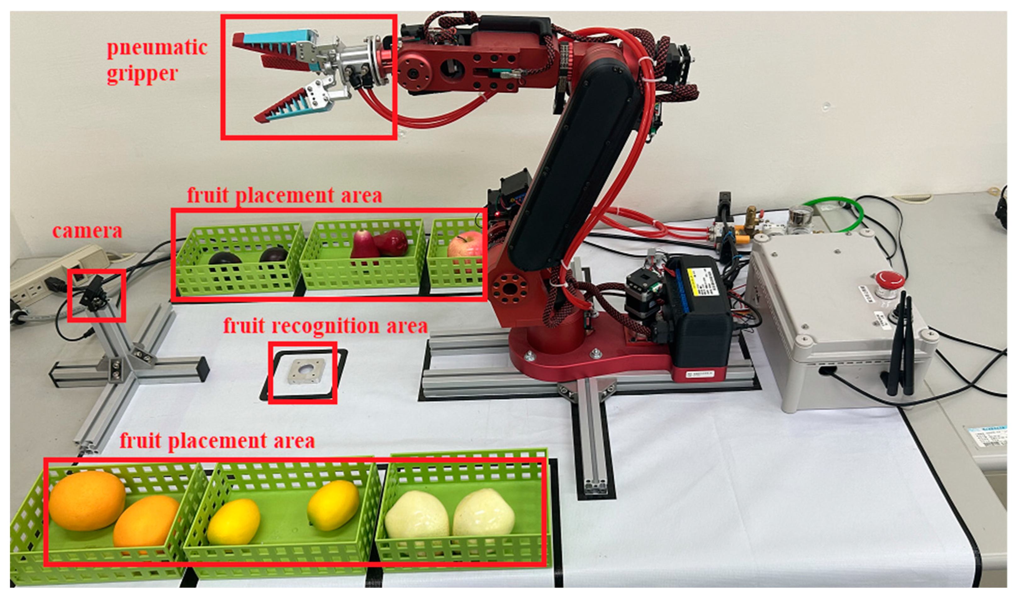
Figure 3.
Parameter explanation diagram for the D-H method.
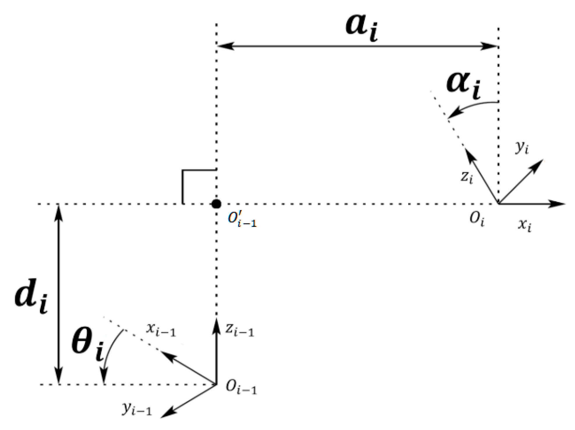
Figure 4.
YOLOv4 development framework.
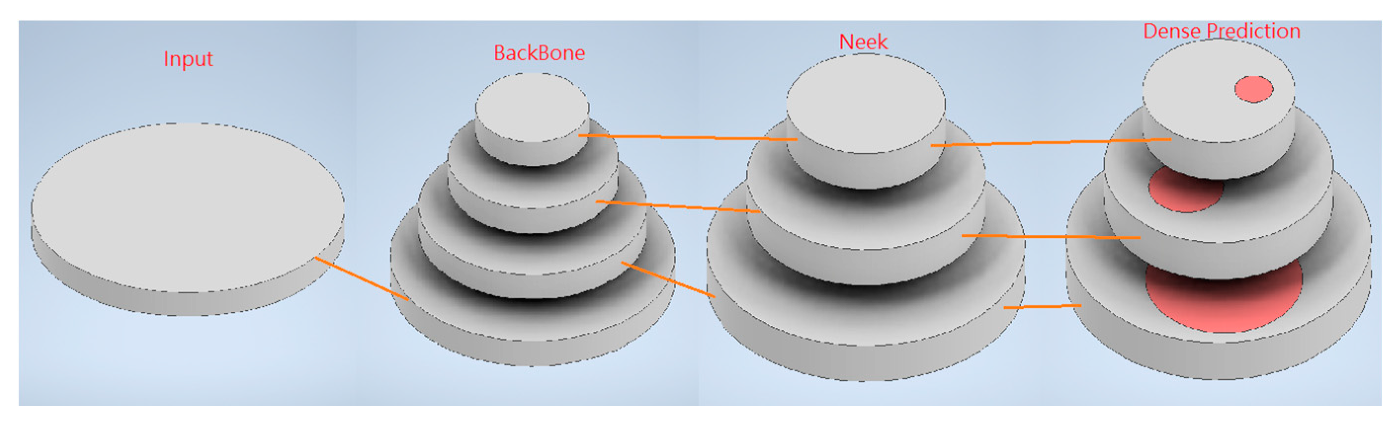
Figure 5.
YOLOv4 architecture.
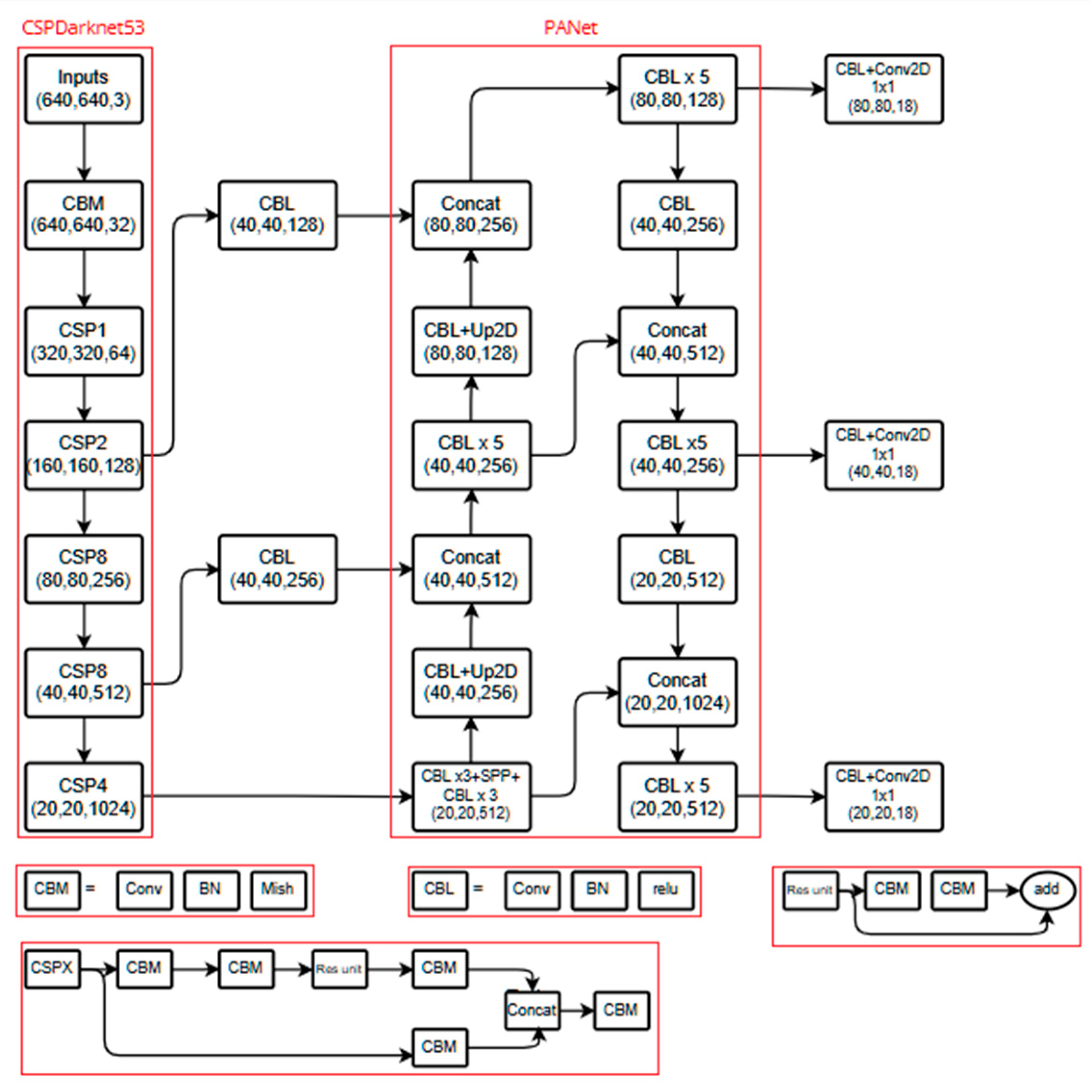
Figure 6.
Training architecture of this experiment.
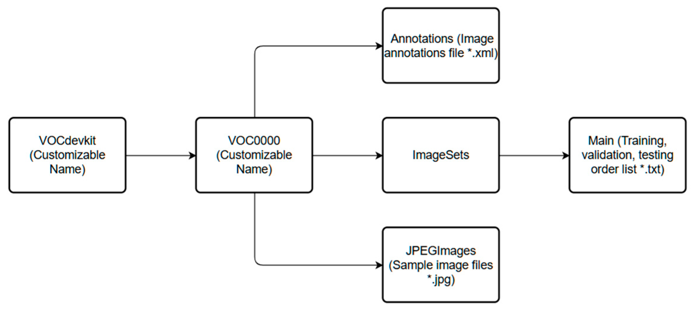
Figure 9.
Splitting the dataset.
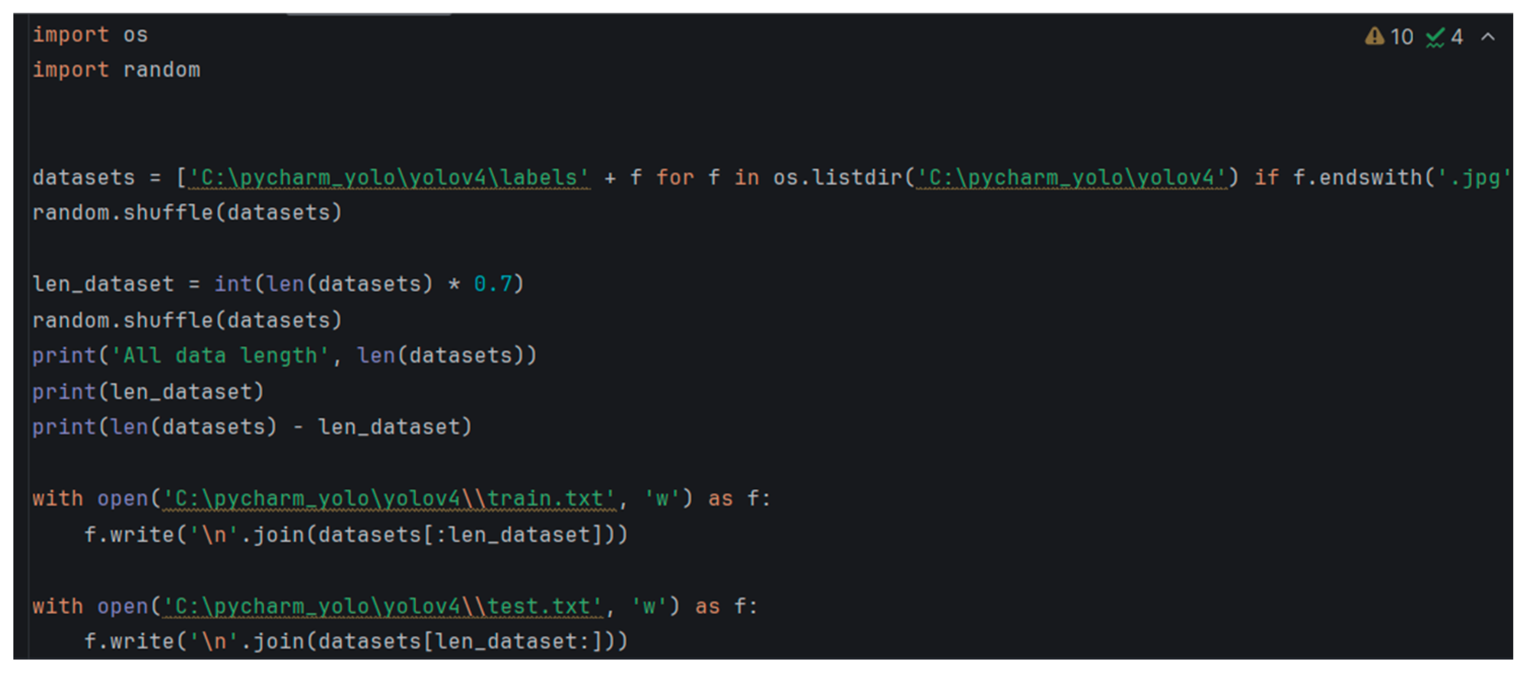
Figure 10.
Modify the filters and classes.
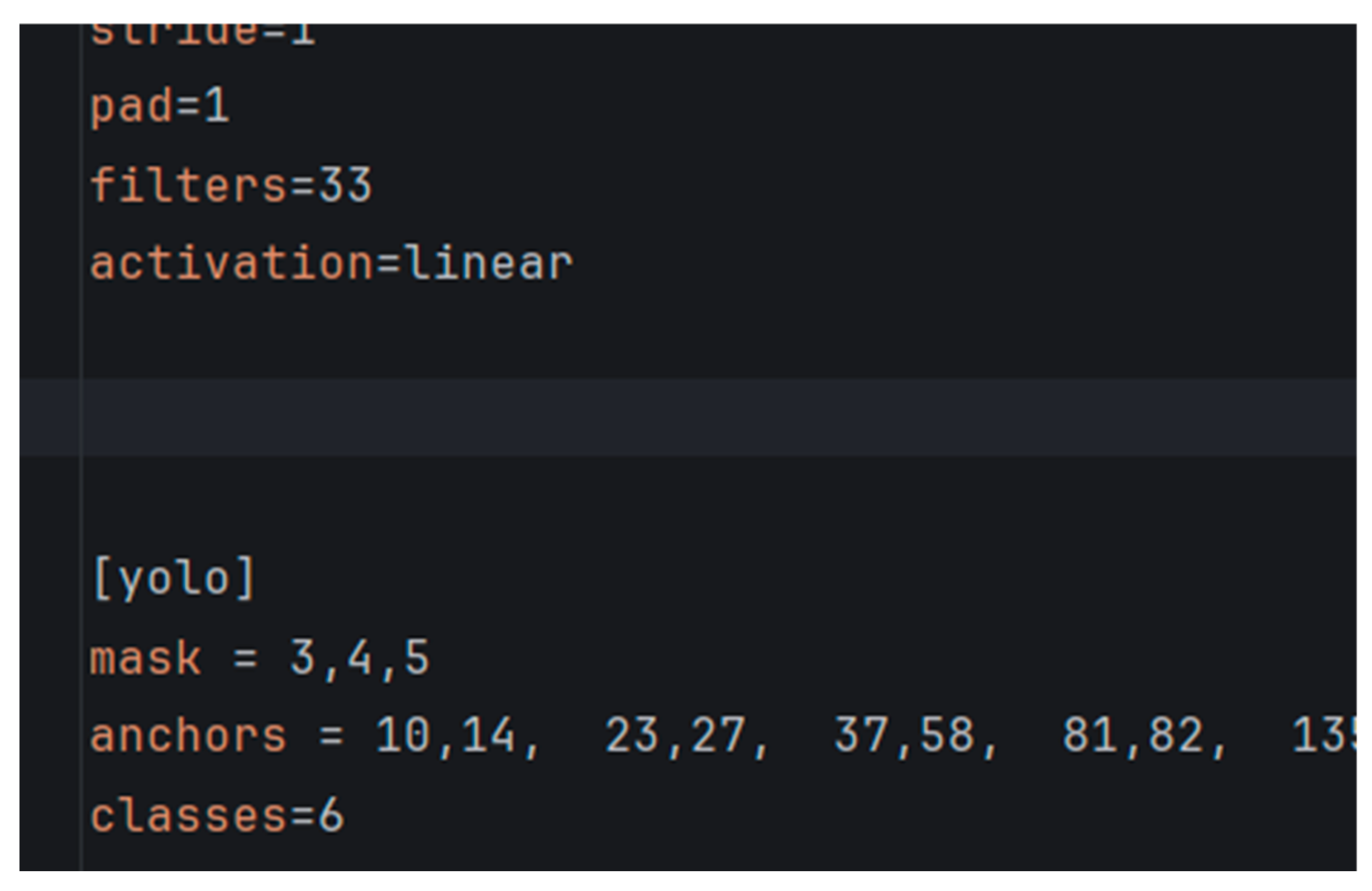
Figure 11.
The pre-trained YOLOv4 model.

Figure 12.
Experimental steps (Using pear as an example).

Figure 13.
Six-angle fruit placement example (pear).
Disclaimer/Publisher’s Note: The statements, opinions and data contained in all publications are solely those of the individual author(s) and contributor(s) and not of MDPI and/or the editor(s). MDPI and/or the editor(s) disclaim responsibility for any injury to people or property resulting from any ideas, methods, instructions or products referred to in the content. |
© 2025 by the authors. Licensee MDPI, Basel, Switzerland. This article is an open access article distributed under the terms and conditions of the Creative Commons Attribution (CC BY) license (http://creativecommons.org/licenses/by/4.0/).
Copyright: This open access article is published under a Creative Commons CC BY 4.0 license, which permit the free download, distribution, and reuse, provided that the author and preprint are cited in any reuse.


