Preprint
Article

This version is not peer-reviewed.

Spectrum Sharing Design for Integrated Aeronautical Communication and Radar System

A peer-reviewed article of this preprint also exists.

Submitted:

28 February 2025

Posted:

03 March 2025

You are already at the latest version

Abstract

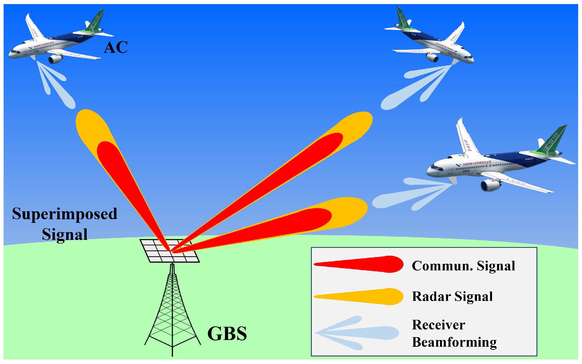
The novel framework of an integrated aeronautical communication and radar system (IACRS) to realize spectrum sharing is investigated. A non-orthogonal multiple access (NOMA)- motivated multi-input-multi-output (MIMO) scheme is proposed for the dual-function system, which is able to detect multiple aircraft while simultaneously transmitting dedicated messages. Specifically, NOMA-inspired technology is utilized to enable the dual-spectrum sharing. The superposition of communication and radar signals is facilitated in the power domain, with successive interference cancellation (SIC) employed at the receiver to effectively mitigate inter-function interference. Subsequently, the regularity of three-dimensional flight track and attitude is exploited to model the air-to-ground (A2G) MIMO channel. Based on this framework, a joint optimization problem is formulated to maximize the weighted achievable sum rate and the sensing signal-clutter-noise ratio (SCNR), while satisfying the rate requirements for message transmission and ensuring the radar detection threshold. An alternative optimization (AO) algorithm is proposed to solve the non-convex problem with highly coupled variables. The original problem is decoupled into two manageable subproblems: transmit beamforming of ground base station combined with power allocation and receiver beamforming at the aircraft. The penalty-based approach and the successive rank-one constraint relaxation (SROCR) method are developed for handling the non-convex rank-one constraints in subproblems iteratively. Numerical simulations demonstrate that the proposed IACRS framework significantly outperforms benchmark schemes.

Keywords: 
;  ;  ;  ;  

1. Introduction

To achieve a safer and more efficient air traffic management (ATM), it is crucial to modernize the aeronautical communications system (ACS)[1]. A new promising ACS for cruise flight safety has emerged, named L-band digital aeronautical communication system (L-DACS), which can significantly improve the operation efficiency of ATM. Additionally, the L-DACS candidate system based on the orthogonal frequency division multiplexing (OFDM) physical-layer technique must be able to operate in the presence of interference from other equipment [2], and also cause the minimum possible interference to legacy systems (e.g., distance measuring equipment (DME) [3] in the same frequency band. This is particularly important since the current ATM system relies on the foundation infrastructure, communication, navigation and surveillance (CNS), which provides critical functions for the safety of aircraft (AC). However, the availability of dedicated frequency spectrum for CNS is struggling to keep up with the increasing saturation of the licensed aviation spectrum band especially in congested airspace. Radar systems, which are used for navigation or surveillance function, have occupied a major portion of the spectrum for civilian aviation operations, leaving the usable spectrum for ACS scarce. Therefore, efficient spectrum utilization strategies are of paramount importance to enhance the performance of integrated CNS system. A cost-efficient strategy for achieving high-quality CNS system performance is to leverage already existing and available technologies such as multiple-input multiple-output (MIMO). It can possess obvious advantages in terms of throughput and reliability by exploiting the spatial-domain channel correlation [4]. Despite the evident merits of MIMO, the effective deployment of CNS is confronted with another challenge, which is the vulnerability of the air-to-ground (A2G) data link. This situation originates from the mutual interference induced by the presence of the various avionics equipment. To address this issue, spectrum sharing between aeronautical communication and radar systems presents a promising solution[5], which has the potential to enable the utilization of additional spectrum resources for communication systems. Consequently, it remains crucial to continue enhancing the spectral efficiency (SE) in order to satisfy the stringent demands of future ACS. In this context, non-orthogonal multiple access (NOMA) has been recognized as a potentially effective technique of improving the SE, as it allows simultaneous multi-user transmission sharing the same resource block [6,7]. Specifically, the core principle of NOMA is to enable the access of multiple users within the same resource blocks while differentiating them in the power domain. This is accomplished by utilizing superposition coding (SC) at the transmitter and successive interference cancellation (SIC) at the receiver [8,9]. In contrast to the design of orthogonal multiple access (OMA), NOMA-based framework can achieve higher SE as serving multiple users in the same resource block, thereby significantly enhancing communication performance.

1.1. Related Works

In recent decades, research interest in communication and radar integration has increased, driven by the goal of suppressing mutual interference and enabling functional collaboration. Generally speaking, existing research on integration can be divided into two main categories: radar and communication coexistence (RCC) [10], and integrated sensing and communications (ISAC) [11]. Although the connotation of terminologies may vary, the sensing functionality primarily refers to radar sensing, which has been a mainstream focus in research. The major distinction between the two categories lies in whether the communication and radar functions are implemented through two separate systems or integrated within a unified framework. The first approach RCC represents a loose form of integration, yielding limited benefits such as reduced signaling overhead and interference suppression [12]. While ISAC delivers both functions using the same waveform, designed to optimize the joint performance of both communication and radar systems [11]. Ultimately, the objective of integration is to surpass the separate functionalities of communication and radar, fostering effective cooperation between them to achieve mutual benefits.

1.1.1. Studies on RCC

The objective of RCC is to provide effective management of the mutual interference between the communication and radar systems, allowing both to operate on the same spectrum and achieve their individual tasks. The study on RCC initially focused on single-antenna techniques, the potential of the OFDM was explored for both communication and radar functions in [13]. The aeronautical spectral coexistence of OFDM communication system and navigation system in L-band was studied in [14], where the pulse blanking technique was employed to mitigate the interference in time domain. Exploiting multiple antennas, the closed-form expression for the optimal transmission waveform was derived to minimize the multi-user interference under different radar sensing criteria in [15]. As an innovative contribution, [16] developed branch-and-bound-based algorithms to investigate the optimal waveform design for RCC within a MIMO framework. Moreover, a precoder for MIMO-radar spectrally-coexistent with a MIMO cellular system is designed [17], where spectrum sharing with zero or minimal interference is achieved by using the proposed space projection. The research in [18] addresses the joint design of the communication and radar systems with co-located antennas focusing on spectrum sharing, aiming to maximize the radar signal-to-interference-plus-noise ratio (SINR) or the communication rate. As a further advance, [19] utilized federated transfer learning for beneficially radar-aided beam prediction in MIMO communication systems to preserve users’ location privacy, where guaranteeing beam prediction accuracy.

1.1.2. Studies on ISAC

By leveraging a joint platform to promote the communication and radar functions, ISAC significantly reduces hardware costs compared to RCC. As a result, ISAC has emerged as a key area of focus in the research on communication and radar integration. The research [20] proposed two sophisticated strategies for implementing ISAC: separated deployment and shared deployment. Both strategies aim to generate high-quality radar beam patterns while meeting communication requirements. Based on the aforementioned antenna deployment strategy, low-complexity beamformer (BF) design algorithms were devised in [21]. To explore the inherent performance boundaries of ISAC, [22] introduced a Pareto optimization framework that characterizes the performance region based on the trade-off between the radar’s peak-to-sidelobe ratio and the SINR attained by the communication user. Additionally, [23] presented a novel joint design of the transmitter and radar receiver, focusing on maximizing the radar’s received SINR for the first time within the ISAC. In [24], a blind beam tracking approach was exploited for UAV-satellite communication system considering the unstable beam pointing due to the UAV navigation. The author in [25] dealt with waveform design of ISAC to improve target detect ability in clutter environment considering the service quality of communication users, while maximizing the output signal-to-clutter-plus-noise ratio (SCNR) of MIMO radar. Furthermore, [26] proposed two types of receiver structures for ISAC systems designed to cancel interference from a priori known dedicated radar signals. Based on these structures, the optimal BF was derived to minimize radar beampattern errors. In [27], a dual-functional base station employing NOMA was designed to serve multiple communication users while simultaneously exploiting the superimposed communication signals for target sensing. Further, [28] investigated a MIMO ISAC base station that detects radar-centric users while transmitting mixed multicast-unicast messages to both radar-centric and communication-centric users within the same spectrum resource.
Note that most of the aforementioned research contributions assume that radar targets are non-communicative and only need to be detected, which differs from scenarios involving aircraft in flight. This assumption essentially treats communication and radar as two isolated systems. Considering the diverse future applications of ACS for ATM, there is a need to develop more sophisticated integration schemes for communication and radar to support a variety of co-located avionics. Although previous works have established a study foundation for spectrum sharing in ground-based wireless communication, the exploration of adopting ISAC in integrated aeronautical communication and radar system (IACRS) remains largely unexplored.

1.2. Motivation and Contributions

As unveiled by the recent works [27,28], the employment of NOMA can offer flexible resource allocation and diverse information transmission options for the communication and radar integration. However, to the best of our knowledge, the interplay between NOMA and ISAC, as well as the potential performance enhancements they may provide, has not been explored in civil aeronautical applications. The primary challenges can be described as follows: 1) The non-convex optimization problem is challenging to solve because of the highly-intertwined variables, including the transceiver BF and the power allocation coefficients; 2) The integration of MIMO introduces additional complexity in the form of A2G channel, leading to intricate interplay between the subproblems. Therefore, the deployment of ISAC in the IACRS to achieve efficient performance needs to be further investigated. In view of this, we propose a novel concept of NOMA-motivated spectrum sharing design for IACRS. For the sake of brevity, the primary contributions of this paper are summarized as follows with explicit comparisons to existing state-of-the-art in Table 1.
  • We in investigate an integrated transmission framework for aeronautical communication and radar system, in which MIMO is utilized at the GBS and ACs to facilitate flexible multiple access scheme, and NOMA is deployed to realize dual-spectrum sharing between the communication and the navigation avionic devices. Given the proposed framework, we formulate a weighted achievable sum rate and the sensing SCNR maximization problem. Aiming for the joint optimization of the GBS transmit BF, the airborne receivers BFs, as well as the power allocation, the minimum operation requirements of both the communication and radar functions is guaranteed.
  • A practical A2G MIMO channel model accounting for the AC dynamics is proposed. This model considers both the AC position and attitude to characterize the steering directions. A rotation matrix is constructed with the AC attitude represented by Euler angles (i.e., heading angle, pitch angle, and roll angle) to derive an equivalent position (EP) given the AC’s current position. Consequently, the realistic angle-of-arrivals (AoAs)/angle-of-departures (AoDs) can be obtained by leveraging the geometrical information.
  • We develop an alternating optimization (AO) algorithm, where the original problem is decomposed into two subproblems that are solved alternatively. By combining the GBS transmit BF and the power allocation subproblems, we construct the auxiliary variables which incorporate the optimization variables, so as to simplify the optimization process. Afterwards, the penalty-based method is invoked to handle the non-convex constraint for the covariance matrix of BF. For the airborne receivers BFs design, we effectively solve them by utilizing the sequential rank-one constraint relaxation (SROCR) while fixing the other optimization variables.
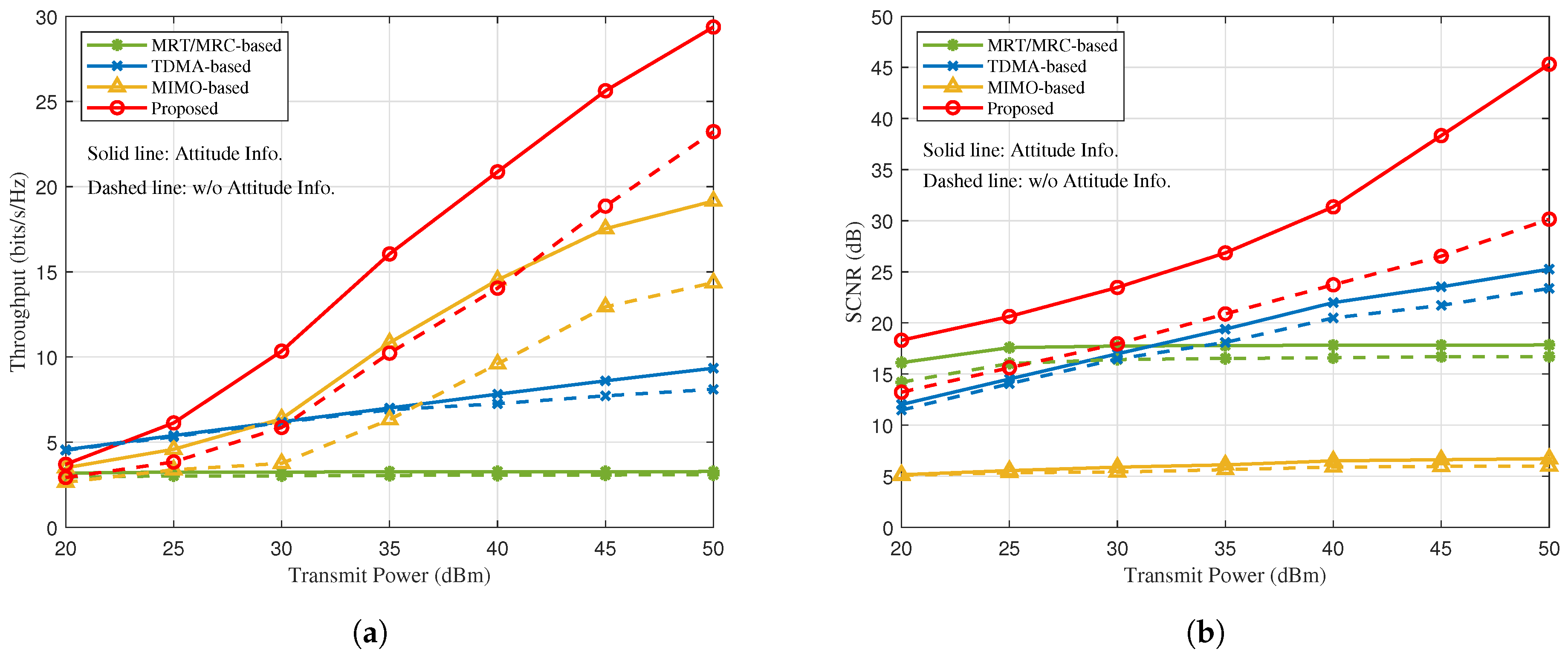
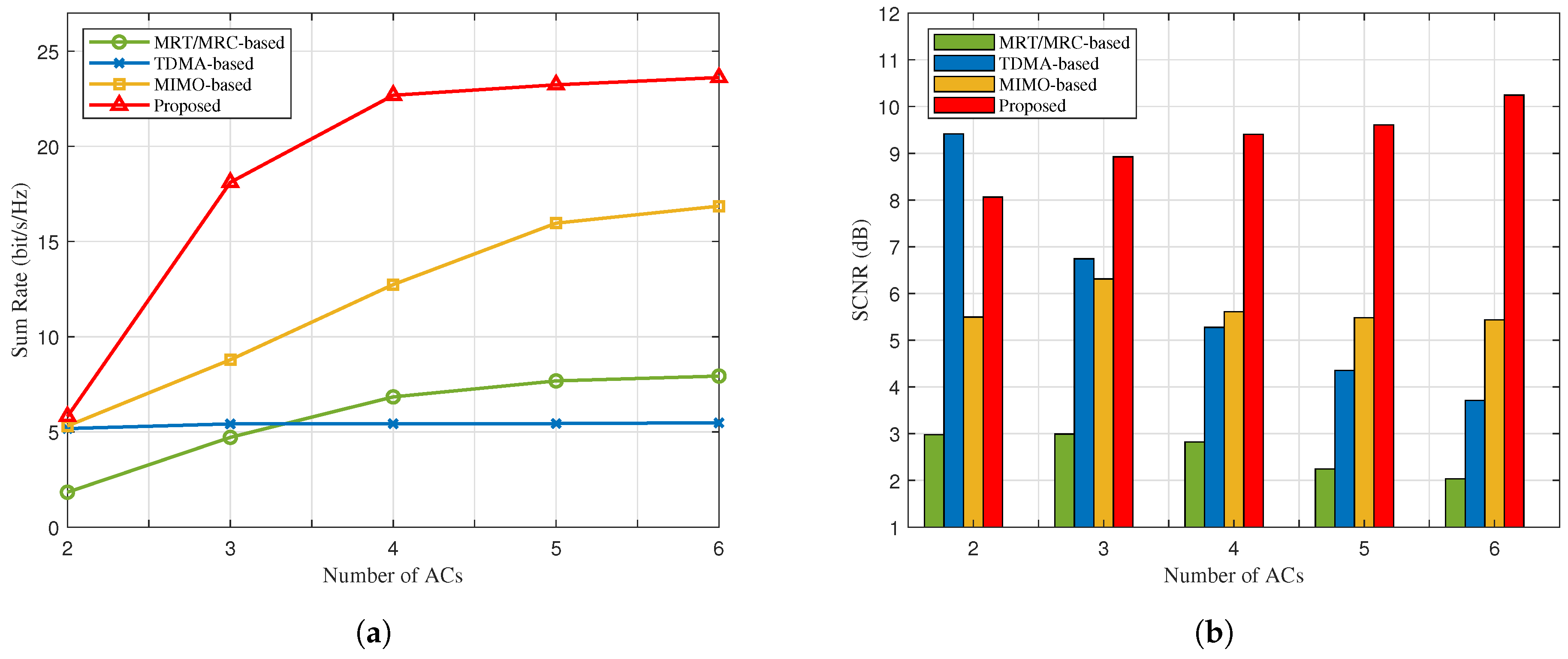
  • Our numerical results indicate that the proposed algorithm achieves superior sum rate performance and sensing performance compared to the benchmark schemes for the dual-function of communication and radar. It is demonstrated that the proposed NOMA-motivated MIMO IACRS schemes are capable of significantly boosting the performance of A2G datalink to support ACs receive messages, while simultaneously constructing a high-quality radar detection capability. Furthermore, the system performance gain becomes more significant, when the AC’s attitude is considered.

1.3. Organization and Notation

The rest of this paper is organized as follows. In Section 2, we introduce the model of IACRS, and formulate the joint sum rate and sensing SCNR problem. In Section 3, an AO-based iterative algorithm is developed to solve the formulated maximizing problem. Numerical results are presented in Section 4 to verify the effectiveness of the proposed algorithms compared to other benchmarks. Finally, conclusions are drawn in Section 5.
Notation: Matrices, vectors and scalars are denoted by bold-face upper-case, bold-face lower-case, and italic letters, respectively. C N × 1 denotes the space of N × 1 complex-valued vectors. For a vector a , a H denotes its (Hermitian) conjugate transpose, and a denotes its Euclidean norm. ; X 0 indicates that matrix X is positive semidefinite; rank ( X ) and Tr ( X ) denote the rank and the trace of X , respectively. X * , X 2 are the nuclear norm and spectral norm of matrix X , respectively. CN ( μ , σ 2 ) denotes the distribution of a circularly symmetric complex Gaussian (CSCG) random variable with mean μ and variance σ 2 . The Kronecker product operator is denoted by ⊗.

2. System Model and Problem Formulation

In this section, we begin by introducing the NOMA-motivated MIMO IACRS model along with the corresponding channel model. Then, we present the coordinate transformation mechanism to illustrate the relationship between the AC’s attitude and the beam pointing. Lastly, we provide the problem formulation.

2.1. System Description

As illustrated in Figure 1, an A2G MIMO integrated communication and radar system is considered. It has a dual-functional ground base station (GBS) and K ACs indexed by k K = 1 , . . . , K . We assume that the communication system and the radar function are allocated on the same frequency band, which is similar to the case of the dedicated bands allocated to L-DACS and DME system. The dual-functional GBS is installed with a uniform planar array (UPA) comprising M G = M G , x × M G , y transmit antennas. The k-th AC is also equipped with a UPA consisted of M A = M A , x × M A , y antennas. Given the A2G multipath components, the digital BFs are employed at both GBS and ACs, so that the transmission of data stream for the k-th AC can be realized.
The dedicated radar sensing signal is assumed to be independent of the information symbols. Let s c , k and s r , k denote the transmitted communication signal and radar sensing signal intended for the k-th AC, respectively. Since the signals transmitted by the GBS in various time blocks have the same form, we focus on the t-th time block, which is consisted of T consecutive time slots, and the time-block index t is omitted in the following. The BF constructed for the k-th AC denoted by the transmit beamforming matrix w k C M G × 1 . Therefore, the transmitted dual-functional signal x C M G × 1 consists of the data signal and sensing signal for all ACs, i.e.,
x = k K w k ( α c , k s c , k + α r , k s r , k ) , k K ,
where α c , k 0 and α r , k 0 denote the power allocation factor of the communication and radar sensing signals of the k-th AC, respectively. Without loss of generality, we have α c , k + α r , k = 1 . Thus, the transmit power of the dual-functional GBS can be calculated as
E ( x x H ) = k K Tr ( w k w k H ) P G ,
where P G is the transmit power constraint for GBS. Different from existing research contributions that multiple communication users served by NOMA [7], NOMA-motivated technology is employed at the GBS to support both communication and sensing function for the same AC in this work. Considering the high-power signal characteristic of DME system with information-embedded, we set the fixed SIC order, as known that the SIC ordering has no influence on the high Signal-to-Noise Ratio (SNR) slope of the ergodic communication rate and the sensing rate [29]. Specifically, the AC first deals with the radar signal by treating the communication signal as interference. The estimated radar signal is then subtracted from received signal with the remaining portion utilized for demodulating and decoding the communication signal. In the following, the radar sensing model and communication model of the proposed system will be introduced.
1) MIMO Radar Sensing Model: Unlike primary radar systems that measure the orientation and distance of targets using the detected reflections of radio signals [30], the DME system relies on targets equipped with a radar transponder. It responds to each interrogation signal by transmitting encoded data containing the requested information. Hence, the transmit beam pattern used for typical radar detection is not a feasible metric considering the operating mode of DME. For the radar sensing function with interrogation mode, we define the SCNR as the key metric. The SCNR represents the radar system’s detection range and sensitivity, which directly influence the probability of detection. It is determined by the gain of the line-of-sight (LoS) path and the situation of clutter. The AC received the superimposed radar sensing signal is given by
y c , k = v k H β 0 a A θ A , LoS , ϕ A , LoS a G H θ G , LoS , ϕ G , LoS x AC target + v k H c clutter + v k H z r , k noise ,
where v k C M A × 1 represents the receive beamforming matrix of the k-th AC adhering to the power constraint Tr ( v k v k H ) P A , k , k K , β 0 denotes the complex amplitude of the LoS, and z r , k C M A × 1 stands for the additive white Gaussian noise (AWGN) satisfying CN ( 0 , I r , k ) . The clutter, represented by c C M A × 1 , follows c CN ( 0 , R c ) including the non-line-of-sight (NLoS). It can generally be modeled as either signal-independent or signal-dependent. In the case of signal-independent clutter, the covariance matrix R c is assumed to remain constant. Conversely, for the signal-dependent clutter, it can be can be modeled as c = l = 1 L β l a A θ A , l , ϕ A , l a G H θ G , l , ϕ G , l x = l = 1 L β l A GA , l x . The steering vectors at the GBS and AC are represented by a G θ G , · , ϕ G , · C M G × 1 and a A θ A , · , ϕ A , · C M A × 1 , respectively. Detailed expressions are provided in Section 2.3. The variables θ G , · and ϕ G , · ( θ A , · and ϕ A , · ) denote the azimuth and elevation components of the AoD at GBS (AoA at AC) for the LoS and NLoS paths, respectively. Given x in (1), the corresponding covariance matrix for the clutter can be calculated as
R c = k = 1 K l = 1 L ( β l A GA , l w k ) ( β l A GA , l w k ) H = k = 1 K l = 1 L β l 2 A GA , l w k w k H A GA , l H .
By employing classical iterative methods [31], R c can be considered constant when the BF matrix keeps fixed from the previous iteration. Consequently, in the subsequent discussion, we will assume that the clutter covariance matrix remains constant during the single iteration. From (3), we set A GA , 0 = a A θ A , LoS , ϕ A , LoS a G H θ G , LoS , ϕ G , LoS as LoS component, the sensing SCNR for the radar signal at the k-th AC is given as
τ k r = α r , k v k H β 0 A GA , 0 w k 2 α c , k v k H β 0 A GA , 0 w k 2 + v k H ( c + z r , k ) 2 .
2) MIMO Communication Model: Given the transmit signal x in (1), the received communication signal of the k-th AC is expressed as
y c , k = v k H h GA , k w k α c , k s c , k desired communication signal + v k H h GA , k w k α r , k s r , k inter - function sensing interference removed by SIC + v k H h GA , k i k K w k ( α c , i s c , i + α r , i s r , i ) inter - aircraft interference not eliminate + n c , k ,
where h GA , k C K A × K G denotes the spatial-frequency domain GBS-AC channel matrix of the k-th AC, n c , k CN ( 0 , σ c 2 I c , k ) . Inspired by NOMA technology, the inter-function interference will be eliminated by exploiting SIC, while treating the signal from other ACs as interference. As a result, the achievable rate of communication message at the k-th AC after SIC is given as
R k c = log 2 ( 1 + α c , k v k H h GA , k w k 2 i k K v k H h GA , k w i 2 + σ c 2 v k 2 ) .
Therefore, the communication throughput for all of the ACs is represented by achievable sum rate. In this study, it is assumed that the channel state information (CSI) can be perfectly estimated to evaluate the maximum performance gain of the proposed IACRS framework. The Doppler shift is a significant factor in aeronautical scenarios, while developing a robust design that accounts for imperfect CSI is beyond the scope of the current work and will be addressed in future research.

2.2. Channel Model

As there are very limited dominant scatterers near to both the GBS and AC in the high-altitude A2G propagation surroundings, we adopt a geometric channel model with one LoS path and L NLoS paths. Assuming that the CSI remains unchanged within each time block1, h GA , k in the t-th time block can be expressed as Rician model,
h GA , k = κ 1 + κ h GA , k LoS + 1 1 + κ h GA , k NLoS , k K ,
where κ denotes the Rician factor, which quantifies the energy ratio between the LoS and NLoS paths. h GA , k LoS is LoS component of k-th AC and it can be expressed as
h GA , k LoS = β LoS a A θ A , LoS , ϕ A , LoS a G H θ G , LoS , ϕ G , LoS .
Similar to the channel state of the LoS path h GA , k LoS , h GA , k NLoS is the set as NLoS component,
h GA , k NLoS = 1 L l = 1 L β l a A θ A , l , ϕ A , l a G H θ G , l , ϕ G , l ,
where L is the number of NLoS rays. Additionally, within channel matrix (9) and (10), β LoS and β l represent the complex-valued gain of the LoS path and NLoS path, respectively.

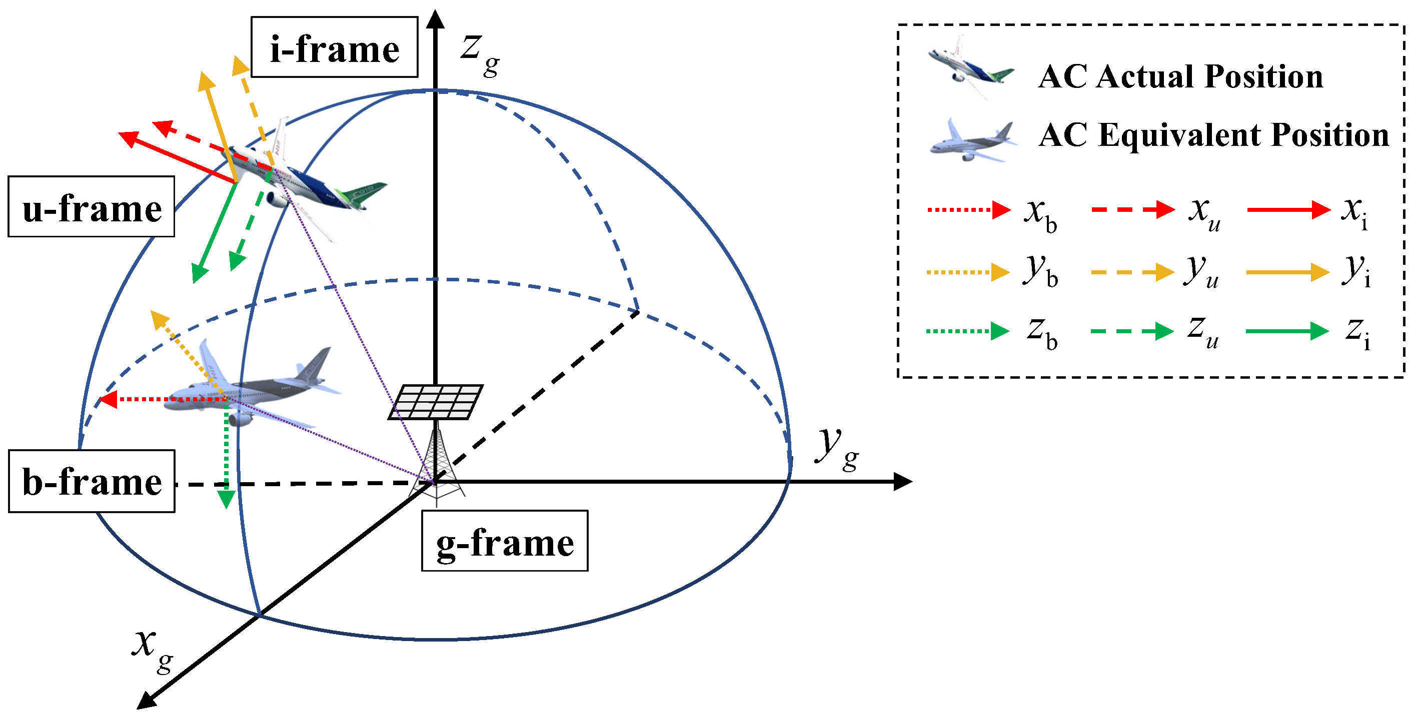
2.3. Coordinate Transformation

The steering directions at the GBS hinge on the AC’s position, while those at the AC side are also influenced by its attitude. To simplify the mathematical notations, we focus on deriving the AoD (denoted by θ G , LoS and ϕ G , LoS ) and AoA (denoted by θ A , LoS and ϕ A , LoS ) of the LoS path, while the AoDs and AoAs of the NLoS paths can be calculated in the similar manner. To appropriately describe the relationship between the AoA (AoD) and the AC’s navigation information, we introduce the following reference frames, which are all illustrated in Figure 2.
  • The GBS-geodetic coordinate frame (g-frame): Its origin is chosen as the center of gravity of the GBS-UPA, and its axis x g and y g are aligned with the directions of east and north, respectively. The axis z g is perpendicular to the ground surface pointing upwards, thus completing a right-handed coordinate frame. We assume that the row and column of the GBS-UPA are aligned with the axes x g and y g , respectively.
  • The AC-body coordinate frame (b-frame): Its origin is the AC center of gravity (ACCG). The axes x b , y b and z b are aligned with its longitudinal (forward), lateral (right), and vertical (downward) direction respectively, which are parallel to x g , y g and z g , respectively.
  • The inertial reference frame (i-frame): Its origin coincides with the ACCG, and its axes x i (roll axis) and y i (pitch axis) point out along the direction of the AC’s head and starboard wing, respectively. And its axis z i (yaw axis) points downward, completing a right-handed coordinate frame.
  • The AC-UPA coordinate frame (u-frame): Its origin is chosen as the AC-UPA center of gravity. The axes x u and y u are aligned with the row and column of the AC-UPA, respectively. The axis z u is perpendicular to the plane spanned by the axes x u and y u . We assume that the axes x u , y u and z u are parallel to x i , y i and z i , respectively. On the basis of the relationship of u-frame and i-frame, the u-frame would be consistent with the i-frame when the attitude of AC changes.
In the g-frame, the GBS’s position is fixed at coordinate origin, while the AC’s position in the t-th time slot is denoted by p g = x g , y g , z g . On the other hand, the AC’s attitude in the t-th time slot is described by its Euler angles E = ψ , θ , ϕ in the i-frame. The angles ψ , θ and ϕ are referred to as the roll, pitch, and yaw angles, respectively. Hence, the i-frame is consistent with the b-frame when the AC’s attitude is E = ( 0 , 0 , 0 ) . Note that the Euler angles are given with a specific rotation order: first around the roll axis, then the pitch axis, and finally the yaw axis. The coordinate transformation matrix C b i expresses the relationship between the b-frame and the i-frame, which can be realized by three successive spatial rotation:
T 1 ( ψ ) = cos ψ sin ψ 0 sin ψ cos ψ 0 0 0 1 , T 2 ( θ ) = cos θ 0 sin θ 0 1 0 sin θ 0 cos θ , T 3 ( ϕ ) = 1 0 0 0 cos ϕ sin ϕ 0 sin ϕ cos ϕ .
The order of the rotations is critical to the orientation of the b-frame [24]. Thus, C b i can be mathematically expressed as
C b i = T 3 ( ϕ ) T 2 ( θ ) T 1 ( ψ ) = cos θ cos ψ cos θ sin ψ sin θ sin ϕ sin θ cos ψ cos ϕ sin ψ sin ϕ sin θ sin ψ + cos ϕ cos ψ sin ϕ cos θ cos ϕ sin θ cos ψ + sin ϕ sin ψ cos ϕ sin θ sin ψ sin ϕ cos ψ cos ϕ cos θ .
Since the GBS and AC positions, as well as the AC attitude, are defined in different coordinate frames, we introduce the concept of AC’s EP in the g-frame to make it tractable for the derivation of the steering vectors. The definition of EP is detailed in Appendix A. Given the p ˜ g and the corresponding AoA, the steering vector of the LoS path at the AC is expressed as
a A θ A , LoS , ϕ A , LoS = a A , x ( μ A , LoS ) a A , y ( ν A , LoS ) ,
where μ A , LoS = 2 π d λ c cos ( θ A , LoS ) sin ( ϕ A , LoS ) and ν A , LoS = 2 π d λ c sin ( θ A , LoS ) sin ( ϕ A , LoS ) represent the spatial frequencies along the axes x u and y u , respectively, with the antenna spacing of d and the carrier wavelength of λ c . The steering vectors a A , x ( μ A , LoS ) and a A , y ( ν A , LoS ) , along the axes x u and y u respectively, are given by
a A , x ( μ A , LoS ) = 1 , e j μ A , LoS , . . . , e j ( M A 1 ) μ A , LoS ,
a A , y ( ν A , LoS ) = 1 , e j ν A , LoS , . . . , e j ( N A 1 ) ν A , LoS .
Similarly, the steering vectors of the NLoS paths at the AC are given by a A θ A , l , ϕ A , l = a A , x ( μ A , l ) a A , y ( ν A , l ) , where the AoAs are respectively replaced by the AoAs of the NLoS paths for the calculations of μ A , l and ν A , l . Furthermore, the steering vectors of the LoS and NLoS paths at the GBS are given by
a G θ G , LoS , ϕ G , LoS = a G , x ( μ G , LoS ) a G , y ( ν G , LoS ) ,
a G θ G , l , ϕ G , l = a G , x ( μ G , l ) a G , y ( ν G , l ) ,
where a G , x ( μ G , LoS ) and a G , x ( μ G , l ) , as well as a G , y ( μ G , LoS ) and a G , y ( μ G , l ) are the steering vectors along the axes x g and y g , respectively.

2.4. Problem Formulation

As discussed in the previous subsection, two conflicting objectives must be addressed in the NOMA-motivated MIMO dual-function IACRS model: maximizing communication throughput and enhancing radar detection capability. To achieve a balance between communication and radar performance, an integrated waveform design is essential. This design should allocate spatial and power resources across the different propagation paths, ensuring that both the communication and radar functions meet their respective performance requirements. Specifically, the goal is to maximize the weighted sum of the achievable sum rate and the sensing SCNR for the system, subject to constraints that include the minimum communication rate for each AC, radar-specific requirements, and the total transmit power budget. The resultant optimization problem is formulated as
max { w k , v k , α c , k , α r , k } f ( R k c , τ k r ) = ρ c k = 1 K R k c + ρ r k = 1 K τ k r ,
s . t . R k c R ¯ k , k K ,
τ k r τ ¯ k , k K ,
k K Tr ( w k w k H ) P G , k K ,
Tr ( v k v k H ) = P A , k , k K
α c , k + α r , k = 1 , k K ,
α c , k 0 , α r , k 0 , k K ,
where ρ c 0 and ρ r 0 represent the regularization parameters, R ¯ k denotes the minimum required communication data rate for the k-th AC. The constraint (16c) defines the minimum required sensing SCNR, with τ ¯ k representing the threshold value for the k-th AC. Additionally, (16d) and (16e) impose the maximum power constraints on the dual-functional GBS and each AC, respectively. The power allocation constraints, given by (16f) and (16g), are essential to ensure the implementation of SIC. The problem (16) is non-convex, arising from the non-convex objective function and the non-convex constraints in (16b) and (16c). These constraints, highly coupled with the transmit BFs of GBS { w k } , power allocation factors { α c , k , α r , k } and the receiver BFs of ACs, { v k } , present significant challenges. Consequently, finding the globally optimal solution is non-trivial. In the following, we propose an AO-based algorithm to find a high-quality near optimal solution.

3. AO-Based Alternative Optimization Algorithm

To tackle the above problems, we propose an AO-based algorithm, which decomposes the original optimization problem into two subproblems: the transmit BFs of GBS combined with power allocation and the receiver BFs of ACs. Each group of variables is iteratively optimized while keeping the others fixed, resulting in an iterative optimization process. The main challenge to solve problem (16) arises from the fact that both the objective function and the left-hand-side (LHS) are non-concave with respect to the optimization variables. To address the issue, the penalty-based approach and the SROCR method are applied for addressing each subproblem iteratively.

3.1. GBS Transmit BFs Design and Power Allocation

We first solve the optimization problem with joint optimizing w k , α c , k and α r , k for given v k . The auxiliary varibles are defined for the covariance matrix of transmit beamforming matrix W k w k w k H , k K , where W k 0 , rank ( W k ) = 1 , and the one for the receiver beamforming matrix V k v k v k H , k K , where V k 0 , rank ( V k ) = 1 . Further, we have equivalent channel h ˜ GA , k = v k H h GA , k . Then, the porblem (16) can be reformulated as
max { W k , α c , k , α r , k } ρ c k = 1 K R k c + ρ r k = 1 K τ k r
s . t . α c , k Tr ( H ˜ GA , k W k ) Γ c , k N k 0 , k K ,
α r , k τ ¯ k v k H R ˜ c v k Tr ( W k Λ v , k ) τ ¯ k α c , k 0 , k K ,
rank ( W k ) = 1 , W k 0 , k K ,
( 16 d ) ( 16 g ) ,
where H ˜ GA , k h ˜ GA , k h ˜ GA , k H , Γ c , k = 2 R ¯ k 1 , N k = i k K v k H h GA , k w i 2 + σ c 2 v k 2 , R ˜ c = R c + I and Λ v , k = β 0 2 A GA , 0 H V k A GA , 0 . Now, the reformulated problem (17) is still non-convex due to the objective function and the non-convex constraints (17c) and (17d). In the following, we first address the non-convex objective function and the constraint (17c). To facilitate this, three auxiliary variables are introduced such that
ϖ r , k 2 = v k H R ˜ c v k = Tr ( V k R ˜ c ) , k K ,
J c , k = α c , k Tr ( H ˜ GA , k W k ) i k K Tr ( H ˜ GA , k W i ) + σ c 2 Tr ( V k ) , k K ,
L r , k = α r , k Tr ( W k Λ v , k ) α c , k Tr ( W k Λ v , k ) + ϖ k 2 .
Subsequently, problem (17) can be equivalently reformulated as
max { W k , α c , k , α r , k } ρ c k = 1 K log 2 ( 1 + J c , k ) + ρ r k = 1 K L r , k
s . t . α r , k τ ¯ k ϖ k 2 Tr ( W k Λ v , k ) τ ¯ k α c , k 0 , k K ,
ϖ r , k 2 v k H R ˜ c v k , k K ,
J c , k α c , k Tr ( H ˜ GA , k W k ) i k K Tr ( H ˜ GA , k W i ) + σ c 2 Tr ( V k ) , k K ,
L r , k α r , k Tr ( W k Λ v , k ) α c , k Tr ( W k Λ v , k ) + ϖ r , k 2 ,
( 16 d ) ( 16 g ) , ( 17 b ) , ( 17 d ) .
This is because, at the optimal solution of (21), it can be obviously verified that constraints (21c), (21d) and (21e) are always satisfied with equality. To illustrate, consider that at the optimal solution of (21), the value of J c , k can be increased to ensure that constraint (21d) is met with strict equality if it was initially satisfied with a strict inequality. This also increases the value of the objective function. We can see the same result when L r , k increased for the constraint (21d). Furthermore, if the constraint (21c) is strictly satisfied, ϖ k can be decreased for guaranteeing the strict equality, while simultaneously increasing the value of the objective function. Hence, problem (21) is equivalent to problem (17).
The objective function in (21) is concave with respect to J c , k , and the second term in the LHS of (21b) is concave jointly with respect to ϖ k 2 and Tr ( W k Λ v , k ) . Moreover, the constraints (21c), (21d) and (21e) are non-convex regarding their respective optimization variables. To handle these, we introduce another two auxiliary variables F c , k and G r , k as
J c , k ( i k K Tr ( H ˜ GA , k W i ) + σ c 2 Tr ( V k ) ) F c , k 2 α c , k Tr ( H ˜ GA , k W k ) ,
L r , k ( α c , k Tr ( W k Λ v , k ) + ϖ k 2 ) G r , k 2 α r , k Tr ( W k Λ v , k ) .
Next, we deal with the constraint (22), which can be equivalently transformed into the following two constraints:
i k K Tr ( H ˜ GA , k W i ) + σ c 2 Tr ( V k ) F c , k 2 J c , k ,
F c , k 2 α c , k Tr ( H ˜ GA , k W k ) .
It is evident that the constraint (24a) is non-convex due to the non-concavity of right-hand-side (RHS), whereas the constraint (24b) is convex. However, the RHS of (24a) is convex function joint with respect to F c , k and J c , k . A lower bound of the RHS of (24a) at the n 1 -th iteration of SCA can be derived by applying the first-order Taylor expression for any given feasible points, { F c , k ( n 1 ) , J c , k ( n 1 ) } , shown as
F c , k 2 J c , k ( F c , k ( n 1 ) ) 2 J c , k ( n 1 ) + 2 F c , k ( n 1 ) J c , k ( n 1 ) ( F c , k F c , k ( n 1 ) ) ( F c , k ( n 1 ) ) 2 ( J c , k ( n 1 ) ) 2 ( J c , k J c , k ( n 1 ) ) = 2 F c , k ( n 1 ) J c , k ( n 1 ) F c , k ( F c , k ( n 1 ) ) 2 ( J c , k ( n 1 ) ) 2 J c , k Υ ( F c , k , J c , k ) , k K .
In a similar way, the constraint (23) also can be equivalently transformed as
α c , k Tr ( W k Λ v , k ) + ϖ k 2 G r , k 2 L r , k ,
G r , k 2 α r , k Tr ( W k Λ v , k ) .
The constraint (26b) is obviously convex. Based on the define of R c in (4), the constraint (26a) can be obtained as
α c , k Tr ( W k Λ v , k ) + Tr ( V k R c ) + Tr ( V k ) G r , k 2 L r , k .
The (26a) is non-convex as its RHS is not concave, while the RHS is convex function joint with respect to G r , k and L r , k . Then, the approximation for the RHS of (26a) can be bounded using the first-order Taylor expansion at feasible points { G r , k ( n 1 ) , L r , k ( n 1 ) } as
G r , k 2 L r , k 2 G r , k ( n 1 ) L r , k ( n 1 ) G r , k ( G r , k ( n 1 ) ) 2 ( L r , k ( n 1 ) ) 2 L r , k Υ ( G r , k , L r , k ) , k K .
For the non-convex constraint (21c), a lower bound can be obtained by the first-order Taylor expression as
ϖ r , k 2 ( ϖ r , k ( n 1 ) ) 2 + 2 ϖ r , k ( n 1 ) ( ϖ r , k ϖ r , k ( n 1 ) ) Ω ( ϖ r , k ) ,
where ϖ r , k ( n 1 ) is the feasible point at the n 1 -th iteration. The LHS of (29) is a convex function with respect to ϖ r , k . Therefore, we have the following reformulated optimization problem:
max X f ( J c , k , L r , k )
s . t . Ω ( ϖ r , k ) v k H R ˜ c v k , k K ,
i k K Tr ( H ˜ GA , k W i ) + σ c 2 Tr ( V k ) Υ ( F c , k , J c , k ) , k K ,
α c , k Tr ( W k Λ v , k ) + ϖ k 2 Υ ( G r , k , L r , k ) , k K ,
( 16 d ) ( 16 g ) , ( 17 b ) , ( 17 d ) , ( 21 b ) , ( 24 b ) , ( 26 b ) ,
where X { W k , α c , k , α r , k , ϖ r , k , J c , k , L r , k , F c , k , G r , k } and f ( J c , k , L r , k ) replaces the original objective function. The non-convexity of this optimization problem arises primarily from the rank-one constraint (17d). A widely adopted approach to tackle this problem is to obtain the semidefinite relaxation (SDR) of the reformulated problem which omits the rank-one constraints By removing the rank-one constraints, SDR could could efficiently obtain a global optimum through convex solvers like CVX. If the obtained solution does not satisfy the rank-one condition, the rank-one solution can be reconstructed through the Gaussian randomization method. The main advantage of SDR is its relatively low computational complexity, as the relaxed problem typically needs to be solved only once. However, the solution derived from the relaxed problem is not guaranteed to be the global optimum of the original problem  (16). One drawback of SDR is that the significant performance degradation may occur due to the reconstruction. The process of reconstructing a rank-one solution can lead to significant performance degradation. Moreover, there is no assurance that the reconstructed rank-one solution will always satisfy all of the constraints for the original problem, potentially resulting in an infeasible solution.
To avoid the drawback, we endeavour to transform the rank-one constraints into penalty terms incorporated within the objective function. This reformulated result can be effectively addressed using SCA considering both solution optimality and feasibility. Building on this concept, the non-convex rank-one constraint (17d) is equivalent to the equality constraint
W k * W k 2 = 0 , k K ,
where · * and · 2 denote the nuclear norm and spectral norm of the matrix, respectively. It can be readily verified that, if the covariance matrix is of rank-one, the above equality constraint (31) is certainly satisfied for any W k satisfying the constrain (17d). Otherwise, the inequality W k * W k 2 > 0 must be hold if the matrices are not rank-one. Thus, the penalty term for the rank-one equality constraint is introduced to the objective function of problem (16), yielding the following optimization problem:
max X f ( J c , k , L r , k ) 1 η k K ( W k * W k 2 ) ,
s . t . ( 16 d ) ( 16 g ) , ( 17 b ) , ( 17 d ) , ( 21 b ) , ( 24 b ) , ( 26 b ) ,
where η is the regularization parameter as penalty factor. The violation of the (31) is penalized by the factor 1 η , when W k are not of rank-one. It is important to recognize that the selection of η has a significant impact on the objective function. As η tends towards 0, causing 1 η to approach , the rank of matrix W k will be definitely one. Nevertheless, in this case, the objective function will be primarily dominated by the penalty term, leading to a bad solution in terms of maximizing both communication throughput and radar detection capability. To tackle this, we can initialize η with a sufficiently large value to obtain a good starting point for the optimization problem. Subsequently, η can be gradually reduced to a sufficiently small value with the update rule η = ε η , 0 < ε < 1 . As a result, feasible rank-one matrix solutions associated with a near-optimal performance can eventually be obtained. However, the spectral norm as the second term in the penalty introduces non-convexity to the objective function. To tackle this, we apply the first-order Taylor expansion around the feasible point W k ( n 1 ) , we could obtain its upper bound W k 2 W ^ k ( n 1 ) of is given by
W ^ k ( n 1 ) W k ( n 1 ) 2 Tr [ u max , k ( n 1 ) ( u max , k ( n 1 ) ) H ( W k W k ( n 1 ) ) ] ,
where u max , k ( n 1 ) is the eigenvector corresponding to the largest eigenvalue of W k ( n 1 ) . Thus, the problrm (32) can be approximated as
min X f ( J c , k , L r , k ) + 1 η k K ( ( W k * + W ^ k ( n 1 ) ) ,
s . t . ( 16 d ) ( 16 g ) , ( 17 b ) , ( 17 d ) , ( 21 b ) , ( 24 b ) , ( 26 b ) .
The problem (34) is a quadratic semidefinite program (QSDP), which can be efficiently addressed using CVX. The iterative procedure will terminate when the penalty term becomes sufficiently small within a predefined accuracy, thereby satisfying the condition k K ( W k * W k 2 ) ϵ 0 . Algorithm 1 provides a comprehensive outline of the penalty-based procedure developed to address problem (17).
Algorithm 1 Penalty-based approach to solve the joint transmit BF design and power allocation subproblem (34)
1:
Initialize feasible points { W k 0 , α c , k 0 , α r , k 0 } and the penalty parameter η .
2:
repeat: outer loop
3:
    Set iteration index n = 0 for inner loop.
4:
    repeat: inner loop
5:
        Use  (18), (19), (20), (22) and (23) to calculate the current value { ϖ r , k ( n 1 ) , J c , k ( n 1 ) , L r , k ( n 1 ) , F c , k ( n 1 ) , G r , k ( n 1 ) } .
6:
        Solve the convex problem (34) with given feasible points, and the obtained optimal varibles are denoted by { W k * , α c , k * , α r , k * } .
7:
         { W k ( n 1 + 1 ) , α c , k ( n 1 + 1 ) , α r , k ( n 1 + 1 ) } by the obtained optimal solutions and n 1 = n 1 + 1 .
8:
    until the fractional for the objective function variation value lowers below a predefined threshold ϵ inner > 0
9:
    Update feasible points { W k 0 , α c , k 0 , α r , k 0 } by the current optimal solutions.
10:
    Update η = ε η .
11:
until the norm difference constraint is lower than the maximum tolerable threshold ϵ outer > 0 .

3.2. ACs Receiver BFs Design

To optimize v k for given w k , α c , k and α r , k , the auxiliary variable g ˜ GA , k = h GA , k w k is introduced, which is the equivalent channel when w k is fixed. It can be observed that the objective function is the addition of a concave function and an affine function. In the following, we also deal with the non-convex objective function and tackle the rank-one constraint. First, we deal with the term for the communication throughput, which can be expressed as
R k c = log 2 ( 1 + α c , k Tr ( V k G ˜ GA , k ) i k K Tr ( V k G ˜ GA , i ) + σ c 2 Tr ( V k ) ) = log 2 ( α c , k Tr ( V k G ˜ GA , k ) + i k K Tr ( V k G ˜ GA , i ) + σ c 2 Tr ( V k ) ) log 2 ( i k K Tr ( V k G ˜ GA , i ) + σ c 2 Tr ( V k ) ) J k ,
where G ˜ GA , k g ˜ GA , k g ˜ GA , k H . The non-convexity of the objective function originates from the second term J k . However, since the objective can be expressed as a difference of two concave functions, a concave lower bound can be established by applying the first-order Taylor expansion at specified feasible points ( V 1 ( n 2 ) , . . . , V K ( n 2 ) ) in the n 2 -th iteration of the algorithm as follows:
J k J ^ k log 2 ( i k K Tr ( V k ( n 2 ) G ˜ GA , i ) + σ c 2 Tr ( V k ( n 2 ) ) ) i k K Tr ( ( V k V k ( n 2 ) ) G ˜ GA , i ) + σ c 2 Tr ( V k V k ( n 2 ) ) ( i k K Tr ( V k ( n 2 ) G ˜ GA , i ) + σ c 2 Tr ( V k ( n 2 ) ) ) ln 2 .
Then, we define
R ^ k c log 2 ( α c , k Tr ( V k G ˜ GA , k ) + i k K Tr ( V k G ˜ GA , i ) + σ c 2 Tr ( V k ) ) + J ^ k ,
which establishes a lower bound for R k c . By leveraging it, the constraint (16b) can be transformed into a conservative approximation with R ^ k c R ¯ k . Next, we tackle the second term of the objective function, a lower bound is given by
τ k r τ ^ k r = log 10 ( α c , k Λ w , k Tr ( V k ) ) log 10 ( α c , k Λ w , k Tr ( V k n ) + Tr ( V k n R ˜ c ) ) α c , k Λ w , k Tr ( V k V k ( n 2 ) ) + Tr ( ( V k V k ( n 2 ) ) R ˜ c ) ( α c , k Λ w , k Tr ( V k ( n 2 ) ) + Tr ( V k ( n 2 ) R ˜ c ) ) ln 10 ,
where Λ w , k = β 0 2 A GA , 0 W k A GA , 0 H . We can observe that τ ^ k r is a convex function with respect to V k . Hence, problem (16) can be rewritten as follows:
max V k f ( V k ) = ρ c k = 1 K R ^ k c + ρ r k = 1 K τ ^ k r ,
s . t . R ^ k c R ¯ k , k K ,
( α r , k Γ r , k α c , k ) β 0 2 Tr ( Λ w , k V k ) Γ r , k Tr ( V k R ˜ c ) 0 ,
rank ( V k ) = 1 , V k 0 , k K ,
( 16 d ) ( 16 g ) ,
where Γ r , k = 10 τ ¯ k 10 . To address the rank-one issue, we invoke the sequential rank-one constraint relaxation (SROCR) method while considering the computing power of avionic computers. The basic framework of the SROCR method is detailed in [32], demonstrating its ability to successively obtain a feasible rank-one solution with favorable complexity. To facilitate this method, the non-convex rank-one constraint (39d) is replaced with the following relaxed convex constraint:
λ max ( V k ) δ ( n 2 ) Tr ( V k ) ,
where λ max ( V k ) is the largest eigenvalue of V k and δ ( n 2 ) [ 0 , 1 ] denotes a relaxation parameter which controls the largest eigenvalue to trace ratio of V k in the n 2 -th iteration of the SROCR algorithm, as the solution V k * is guaranteed to satisfy the following condition:
δ ( n 2 ) λ max ( V k * ) Tr ( V k * ) 1 .
Thus,  (40) will be equivalent to the SDR when δ ( n 2 ) = 0 , which omits the non-convex rank-one constraint. This motivates us to incrementally increase δ ( n 2 ) from 0 in iterations, allowing the transformed constraint to gradually converge to the actual rank-one constraint set as δ ( n 2 ) approaches 1. As a result, problem (39) can be rewritten as the following relaxed optimization problem:
max V k f ( V k ) ,
s . t . ( u max , k ( n 2 ) ) H V k u max , k ( n 2 ) δ ( n 2 ) Tr ( V k ) , k K ,
( 16 d ) ( 16 g ) , ( 39 b ) ( 39 c ) ,
where u max , k ( n 2 ) is the eigenvector corresponding to the largest eigenvalue of V k ( n 2 ) , which is the obtained solution feasible with δ ( n 2 ) . Now, the problem (42) has been reformulated into a convex problem, which can be solved using optimization tools such as CVX [33]. The optimal value obtained from (42) serves as a lower bound for the original problem. This is because the non-convex components have been replaced with their respective lower bound approximations, ensuring that the solution reflects a conservative result of the original problem. After each iteration, relaxation parameter δ ( n 2 ) is updated as
δ ( n 2 ) = min ( 1 , λ max ( V k ( n 2 ) ) Tr ( V k ( n 2 ) ) + σ ( n 2 ) ) ,
where σ ( n 2 ) is a predefined step size. If the problem (42) is infeasible at the current step σ ( n 2 ) , we will reduce the step size as σ ( n 2 + 1 ) = σ ( n 2 ) / J , where J 2 in order to speed up making (42) solvable. Setting f ( V k ( n 2 ) ) as the objective function value achieved by solution V k ( n 2 ) , the algorithm will be terminated when f ( V k ( n 2 ) ) f ( V k ( n 2 1 ) ) ϵ 1 and 1 δ ( n 2 1 ) ϵ 2 are simultaneously satisfied, where ϵ 1 and ϵ 2 are convergence thresholds. Hence, the proposed method can be assured to converge to a locally optimal solution with rank-one constraint [34] by iteratively updating parameter δ ( n 2 ) and solving problem (42). The details to solve problem (39) with the SROCR method are summarized in Algorithm 2.
Algorithm 2 SROCR method for solving the receiver BF design subproblem (42)
1:
Initialize convergence thresholds ϵ 1 and ϵ 2 , step size σ ( n 2 ) , relaxation parameter δ ( n 2 ) , and n 2 = 0 .
2:
repeat
3:
    For given { δ ( n 2 ) , V k ( n 2 ) } , solve the problem (42).
4:
    if problem (42) is feasible then
5:
         V k ( n 2 + 1 ) = V k , σ ( n 2 + 1 ) = σ ( 0 ) .
6:
    else
7:
         V k ( n 2 + 1 ) = V k ( n 2 ) , σ ( n 2 + 1 ) = σ ( n 2 ) / J .
8:
    end if
9:
     n 2 = n 2 + 1 ,
10:
    update δ ( n 2 ) = min ( 1 , λ max ( V k ( n 2 ) ) Tr ( V k ( n 2 ) ) + σ ( n 2 ) ) .
11:
until f ( V k ( n 2 ) ) f ( V k ( n 2 1 ) ) ϵ 1 and 1 δ ( n 2 1 ) ϵ 2 . V k * = V k ( n 2 ) .

3.3. Complexity Analysis

Following the above discussions, the proposed AO-based alternative algorithm is utilized to address the original problem (16), which starts by initializing a feasible solution, including the aforementioned two subproblems. The main computational burden of proposed AO-based algorithm is primarily determined by the complexities of Algorithm 1 and Algorithm 2. Given the solution accurancy E , the complexity Algorithm 1 is O ( I o I i ( K M G 3.5 + ( 7 K ) 3.5 ) log ( 1 / E ) ) , where I i , I o and 7 K denote the number of inner and outer iterations required for convergence, and the number of scalar optimization variables, respectively. Considering the relaxed problem (42) being a standard SDP, Algorithm 2 exhibits a complexity of O ( ( K M A 3 ) log ( 1 / E ) ) . Thus, the total computational complexity of proposed AO-based algorithm given by is O ( ( I o I i ( K M G 3.5 + ( 7 K ) 3.5 ) + K M A 3 ) log ( 1 / E ) ) .

4. Numerical Results

To evaluate the performance of the proposed IACRS, we present numerical results obtained from Monte Carlo simulations in this section. In particular, we assume that the GBS and ACs are all equipped with UPA with same number of elements M G = M A = 4 × 4 , which is of half-wavelength spacing between adjacent antennas. The number of aircraft is 2 in default scenario. The channels between GBS and ACs are assumed to experience Rician fading with the path loss of L k = L 0 + 20 log 10 ( d k ) ( dB ) , where L 0 is the path loss at the reference distance d = 1 meter (m), and d k represents the distance from the GBS [20]. The parameter settings are setting as R ¯ k = 0.5 bit/s/Hz, τ ¯ k = 1 dB and P G = P A ( k ) = 30 dBm, k K unless specified otherwise. The initial penalty factor of Algorithm 1 is set to η = 10 5 , and the convergence thresholds of inner and outer loops are set to ϵ inner = 1.001 and ϵ outer = 10 5 . The initial step size of Algorithm 2 is set to σ ( 0 ) = 0.1 , and the convergence thresholds for difference in objective function and relaxation parameter is set to ϵ 1 = 10 3 and ϵ 2 = 10 5 , respectively. All numerical results are obtained using 300 Monte-Carlo simulations with random channel realizations. For performance comparison, we consider the following benchmark schemes.
  • TDMA-based dual-function scheme: In this scheme, the GBS with multi-antenna successively transmits dedicated messages and interrogation detecting singal to ACs over 2 K time slots employing one common BF. Accordingly, for TDMA-based scheme, the sensing SCNR at the k-th AC is given by
    τ k TDMA = 1 2 K v k H β 0 A GA , 0 w k 2 v k H ( c + z r , k ) 2 ,
    the corresponding achievable rate for the k-th AC is
    R k TDMA = 1 2 K log 2 ( 1 + v k H h GA , k w k 2 σ c 2 v k 2 ) .
    The problem of maximizing sum of τ k TDMA and R k TDMA can be solved by using SCA algorithm, as there are no inter-aircraft or inter-function interference terms involved.
  • MIMO-based dual-function scheme: In this scheme, the MIMO-only GBS transmits communication data to the ACs employing distinct BFs, which are also simultaneously utilized for the detection of the ACs. Notably, each AC directly receives its intended signal while treating the signals for other ACs as interference without the assistance of SIC, which means a low level of integration. Therefore, the sensing SCNR and the sum rate for the transmitted signal at the AC are similar with (3) and (6), respectively.
  • MRT/MRC-based dual-function scheme: In this scheme, the system model is same as the proposed integrated framework, while using a linear transmitter and receiver, maximum-ratio transmission/maximum-ratio combining (MRT/MRC)[35]. Hence, the approximate closed-form expressions of the transmit BFs of GBS and the receiver BFs of ACs can be obtained.
In Figure 3, the convergence behavior of the proposed algorithm is studied with varying values of the reduction factor ϵ . The numerical results indicate that the objective function rapidly converges to a stable value for any values of the reduction factor, while the rank-one term approaches nearly zero after a few iterations. This behavior confirms the convergence of the proposed algorithm. It demonstrates that the algorithm effectively identifies a feasible rank-one solution with high performance, applicable to both GBS transmitter and airborne receiver. Furthermore, the results reveal that as the parameter ϵ decreases, the algorithm achieves faster convergence speed but results in lower objective values, which corresponds to reduced system performance. This highlights a trade-off between convergence speed and system performance.
In Figure 4, we use the equivalent norm difference, W k * W k 2 , V k * V k 2 , k K , as evaluation metric to assess results of both the penalty-based approach and the SROCR method for the rank-one constraint. It is also observed that the value of σ has little or no effect on the rank-one term, so we only focus on selecting ϵ in Figure 3. Additionally, as ϵ decreases, the proposed algorithm exhibits faster convergence but leads to a lower objective value, i.e., worse system performance, reflecting a trade-off. Therefore, in the following simulations, we set ϵ = 0.1 , which provides a balance between convergence speed and system performance.
We evaluate the impact of the AC’s number on the proposed IACRS framework in Figure 5. It is shown that the weighted sum of the achievable sum rate and sensing SCNR in the proposed scheme increases consistently during the iterations, regardless of the number of ACs. Specifically, the number of iterations increases as the number of ACs grows. For instance, when K = 2 , the objective value gradually rises over approximately 7 iterations before converging to a stable value. However, when the number of ACs is increased to K = 5 , the number of iterations rises to around 12, due to the expanded search space resulting from the increased number of ACs.
In Figure 6, we first present the obtained achievable sum rate versus the transmit power P G in Figure 6a. It can be observed that the achievable sum rate of all schemes increases with increasing transmit power. Furthermore, the performance enhancement attained by NOMA-motivated framework upon increasing P G is more significant than that of TDMA-based scheme, since NOMA benefits from a flexible resource allocation scheme enabling the double spectrum sharing. In Figure 6b, we also present the sensing SCNR obtained by the four schemes. It can be observed that the proposed scheme outperforms the other baseline scheme especially at high transmit power. The SCNR gain achieved with effective attitude information, compared to position-only information, becomes more pronounced as transmit power increases. However, in contrast to TDMA-based and proposed scheme, the sensing SCNR achieved by the MIMO-based scheme seems to be bounded by a certain value, with its enhancement becoming negligible. This is because, in the absence of interference mitigation, the MIMO-based scheme becomes interference-limited. These results demonstrate that the proposed NOMA-motivated MIMO IACRS scheme is particularly suitable for aeronautical A2G communication in environments with saturated dedicated spectrum resources, while providing high-quality sensing SCNR for multiple aircraft detection in secondary radar applications.
Further investigation of the achievable sum rate and average SCNR versus the number of ACs is given in Figure 7. We consider different scenrios for AC’s number as K = { 2 , 3 , 4 , 5 , 6 } , with their azimuth positions given by the sets [ 0 , π 2 ] , [ 0 , π 2 , π ] , [ 0 , π 2 , π , 3 π 2 ] , [ 0 , π 2 , π , 3 π 2 ] , [ 0 , π 3 , 2 π 2 , π , 4 π 3 ] , [ 0 , π 3 , 2 π 2 , π , 4 π 3 , 5 π 3 ] , respectively. All ACs remain at an elevation angle of π 3 , which is consistent with typical cruise situation. It can be observed that the sum rate of all schemes, except the TDMA-based scheme, first increases and then converges as K adds. This trend can be explained as follows: for small values of K, increasing the number of ACs provides more spatial degrees of freedom (DoFs), which can be exploited to maximize the sum rate. However, as K becomes larger, the azimuth angles between the ACs become smaller leading to increased channel correlation, which limits system performance.
It is also seen that the average SCNR of the MIMO-based scheme first increases (from 2 to 3 ACs) and then decreases (from 3 to 6 ACs) as K increases. The proposed scheme, utilizing the AO-based algorithm, is the only one for which the average SCNR consistently increases with the number of ACs. This result highlights that the MRT/MRC scheme does not benefit from the NOMA-motivated framework, thus leading to a degradation in radar sensing performance. Additionally, it is observed that TDMA-based scheme has a significantly lower average SCNR, which is due to the reduction in available time slots allocated to the sensing function of a single AC as the number of ACs increases.
In Figure 8, the simulation results highlight the trade-off between sensing SCNR and sum rate in proposed system under varying NLoS conditions. As the number of NLoS paths increases, SCNR initially improves but eventually degrades due to the growing clutter from excessive multipath components. In contrast, the sum rate generally benefits from the presence of NLoS paths, reflecting the system’s ability to exploit spatial diversity. However, this improvement saturates as the system approaches its capacity to effectively handle multipath propagation. Additionally, it is clear that increasing the number of UPA elements results in a noticeable performance gain. In summary, there exists a trade-off between achieving higher data rates and maintaining sensing signal quality, as more NLoS components increase capacity but also introduce greater interference. To optimize system performance, careful management of multipath effects is essential to mitigate clutter while maximizing the benefits of spatial diversity.

5. Conclusion and Discussion

This paper proposes a novel NOMA-motivated MIMO dual-function scheme for IACRS, where a MIMO GBS transmits NOMA-structured superimposed radar sensing signals and communication messages to the ACs achieving double spectrum sharing. For the proposed framework, corresponding BF optimization and power allocation problems are formulated for enhancing both communication and radar performance, while fulfilling the transmitted data rate and the sensing SCNR requirements. An AO-based algorithm is developed to find a near-optimal solution to solve the resultant non-convex optimization problem. The main findings of the research are summarized as follows:
  • A new A2G MIMO channel model that accounts for AC dynamics, including both position and attitude, is introduced to accurately characterize the steering direction. Since the AoDs and AoAs depend on the time-varying position and attitude, the proposed channel model significantly improves system performance, both in the proposed scheme and the baseline.
  • To validate the effectiveness of the proposed scheme, it is compared with three baselines. The numerical results demonstrate that the proposed scheme achieves superior dual-function system performance compared to the benchmark schemes. In contrast, the MRT/MRC scheme does not benefit from the NOMA-motivated framework, as it relies only on valid channel information, resulting in inferior communication performance.
  • One limitation of our framework is that obtaining accurate CSI becomes challenging due to the time-varying nature of A2G wireless channels and AC mobility, which directly impacts system performance. Addressing imperfect CSI could be a direction for future work. Additionally, the SIC process requires significant computational resources, and in low SNR environments, its performance may degrade substantially, leading to erroneous signal decoding and severely affecting system stability and data transmission quality.

Author Contributions

Conceptualization, L.Y. and J.Z.; methodology, L.Y. and Q.Z.; software, L.Y.; validation, L.Y. and Q.Z.; formal analysis, L.Y.; investigation, L.Y.; resources, J.Z. and C.K.; data curation, L.Y.; writing—original draft preparation, L.Y.; writing—review and editing, Q.Z. and J.Z.; visualization, L.Y.; supervision, J.Z. and Y.Z.; project administration, J.Z., Y.Z. and C.K.; funding acquisition, J.Z. and C.K. All authors have read and agreed to the published version of the manuscript.

Funding

This research is supported by the Funds of National Natural Science Foundation of China (Grant No. U2133210, U2233216) and the Fundamental Research Funds for the Central Universities (No. YWF-24-JT-102).

Data Availability Statement

The data presented in this study are available on request from the corresponding author. The data are not publicly available due to privacy.

Conflicts of Interest

The authors declare no conflicts of interest.

Appendix A

This appendix provides the formal definition and proposition regarding the concept of the Aircraft’s Equivalent Position (EP), which is critical to understanding the derivation of AoDs/AoAs under varying aircraft positions and attitudes.
Definition A1. 
p ˜ g is named as the AC’s EP with respect to its current position p g . The AC’s EP in the g-frame, p ˜ g = x ˜ g , y ˜ g , z ˜ g , corresponds to the position where the AC, with attitude E = ψ , θ , ϕ and current position p g , results in the same AoA as when the AC has attitude E ˜ = ( 0 , 0 , 0 ) and p ˜ g .
In simpler terms, while the AoA depends on the AC’s position and attitude, it can equivalently be described solely by its EP. Then the AC’s EP p ˜ g = x ˜ g , y ˜ g , z ˜ g can be derived as p ˜ g = C b i p g , where p ˜ g and p g lie on the same sphere centered at the GBS. Additionally, it can be observed that det ( C b i ) = 1 . Thus, we can conclude p g = p ˜ g .

References

  1. Zhang, J. Aeronautical Mobile Communication: The Evolution from Narrowband to Broadband. Engineering 2021, 7, 431–434. [Google Scholar] [CrossRef]
  2. Schnell, M.; Epple, U.; Shutin, D.; Schneckenburger, N. LDACS: future aeronautical communications for air-traffic management. IEEE Commun. Mag. 2014, 52, 104–110. [Google Scholar] [CrossRef]
  3. Neji, N.; de Lacerda, R.; Azoulay, A.; Letertre, T.; Outtier, O. Survey on the Future Aeronautical Communication System and Its Development for Continental Communications. IEEE Trans. Veh. Technol. 2013, 62, 182–191. [Google Scholar] [CrossRef]
  4. Xiao, Z.; Zhu, L.; Liu, Y.; Yi, P.; Zhang, R.; Xia, X.G.; Schober, R. A Survey on Millimeter-Wave Beamforming Enabled UAV Communications and Networking. IEEE Commun. Surveys Tuts. 2022, 24, 557–610. [Google Scholar] [CrossRef]
  5. Luong, N.C.; Lu, X.; Hoang, D.T.; Niyato, D.; Kim, D.I. Radio Resource Management in Joint Radar and Communication: A Comprehensive Survey. IEEE Commun. Surv. Tut. 2021, 23, 780–814. [Google Scholar] [CrossRef]
  6. Ding, Z.; Liu, Y.; Choi, J.; Sun, Q.; Elkashlan, M.; Chih-Lin, I.; Poor, H.V. Application of Non-Orthogonal Multiple Access in LTE and 5G Networks. IEEE Commun. Mag. 2017, 55, 185–191. [Google Scholar] [CrossRef]
  7. Liu, Y.; Qin, Z.; Elkashlan, M.; Ding, Z.; Nallanathan, A.; Hanzo, L. Nonorthogonal Multiple Access for 5G and Beyond. Proc. IEEE 2017, 105, 2347–2381. [Google Scholar] [CrossRef]
  8. Liu, Y.; Qin, Z.; Elkashlan, M.; Gao, Y.; Hanzo, L. Enhancing the Physical Layer Security of Non-Orthogonal Multiple Access in Large-Scale Networks. IEEE Trans. Wireless Commun. 2017, 16, 1656–1672. [Google Scholar] [CrossRef]
  9. Zhu, L.; Zhang, J.; Xiao, Z.; Cao, X.; Wu, D.O.; Xia, X.G. Millimeter-Wave NOMA With User Grouping, Power Allocation and Hybrid Beamforming. IEEE Trans. Wireless Commun. 2019, 18, 5065–5079. [Google Scholar] [CrossRef]
  10. Zheng, L.; Lops, M.; Eldar, Y.C.; Wang, X. Radar and Communication Coexistence: An Overview: A Review of Recent Methods. IEEE Signal Process. Mag. 2019, 36, 85–99. [Google Scholar] [CrossRef]
  11. Liu, F.; Cui, Y.; Masouros, C.; Xu, J.; Han, T.X.; Eldar, Y.C.; Buzzi, S. Integrated Sensing and Communications: Toward Dual-Functional Wireless Networks for 6G and Beyond. IEEE J. Sel. Areas Commun. 2022, 40, 1728–1767. [Google Scholar] [CrossRef]
  12. Zhang, A.; Rahman, M.L.; Huang, X.; Guo, Y.J.; Chen, S.; Heath, R.W. Perceptive Mobile Networks: Cellular Networks With Radio Vision via Joint Communication and Radar Sensing. IEEE Veh. Technol. Mag. 2021, 16, 20–30. [Google Scholar] [CrossRef]
  13. Sturm, C.; Zwick, T.; Wiesbeck, W. An OFDM System Concept for Joint Radar and Communications Operations. In Proceedings of the Proc. VTC Spring- IEEE 69th Veh. Technol. Conf. IEEE, Barcelona, Spain, Jun. 2009; pp. 1–5. [Google Scholar]
  14. Agrawal, N.; Darak, S.J.; Bader, F. Spectral Coexistence of LDACS and DME: Analysis via Hardware Software Co-Design in Presence of Real Channels and RF Impairments. IEEE Trans. Veh. Technol. 2020, 69, 9837–9848. [Google Scholar] [CrossRef]
  15. Sturm, C.; Wiesbeck, W. Waveform Design and Signal Processing Aspects for Fusion of Wireless Communications and Radar Sensing. Proc. IEEE 2011, 99, 1236–1259. [Google Scholar] [CrossRef]
  16. Liu, F.; Zhou, L.; Masouros, C.; Li, A.; Luo, W.; Petropulu, A. Toward Dual-functional Radar-Communication Systems: Optimal Waveform Design. IEEE Trans. Signal Process. 2018, 66, 4264–4279. [Google Scholar] [CrossRef]
  17. Mahal, J.A.; Khawar, A.; Abdelhadi, A.; Clancy, T.C. Spectral Coexistence of MIMO Radar and MIMO Cellular System. IEEE Transactions on Aerospace and Electronic Systems 2017, 53, 655–668. [Google Scholar] [CrossRef]
  18. Qian, J.; Lops, M.; Zheng, L.; Wang, X.; He, Z. Joint System Design for Coexistence of MIMO Radar and MIMO Communication. IEEE Trans. Signal Process. 2018, 66, 3504–3519. [Google Scholar] [CrossRef]
  19. Zhou, Q.; Gong, Y.; Nallanathan, A. Radar-Aided Beam Selection in MIMO Communication Systems: A Federated Transfer Learning Approach. IEEE Trans. Veh. Technol. 2024, 73, 12172–12177. [Google Scholar] [CrossRef]
  20. Liu, F.; Masouros, C.; Li, A.; Sun, H.; Hanzo, L. MU-MIMO Communications With MIMO Radar: From Co-Existence to Joint Transmission. IEEE Trans. Wireless Commun. 2018, 17, 2755–2770. [Google Scholar] [CrossRef]
  21. Dong, F.; Wang, W.; Hu, Z.; Hui, T. Low-Complexity Beamformer Design for Joint Radar and Communications Systems. IEEE Commun. Lett. 2021, 25, 259–263. [Google Scholar] [CrossRef]
  22. Chen, L.; Liu, F.; Wang, W.; Masouros, C. Joint Radar-Communication Transmission: A Generalized Pareto Optimization Framework. IEEE Trans. Signal Process. 2021, 69, 2752–2765. [Google Scholar] [CrossRef]
  23. Tsinos, C.G.; Arora, A.; Chatzinotas, S.; Ottersten, B. Joint Transmit Waveform and Receive Filter Design for Dual-Function Radar-Communication Systems. IEEE J. Sel. Areas Commun. 2021, 15, 1378–1392. [Google Scholar] [CrossRef]
  24. Zhao, J.; Gao, F.; Wu, Q.; Jin, S.; Wu, Y.; Jia, W. Beam Tracking for UAV Mounted SatCom on-the-Move With Massive Antenna Array. IEEE J. Sel. Areas Commun. 2018, 36, 363–375. [Google Scholar] [CrossRef]
  25. Zhu, J.; Li, W.; Wong, K.K.; Jin, T.; An, K. Waveform Design of DFRC System for Target Detection in Clutter Environment. IEEE Signal Process. Lett. 2023, 30, 1517–1521. [Google Scholar] [CrossRef]
  26. Chen, L.; Wang, Z.; Du, Y.; Chen, Y.; Yu, F.R. Generalized Transceiver Beamforming for DFRC With MIMO Radar and MU-MIMO Communication. IEEE J. Sel. Areas Commun. 2022, 40, 1795–1808. [Google Scholar] [CrossRef]
  27. Wang, Z.; Liu, Y.; Mu, X.; Ding, Z.; Dobre, O.A. NOMA Empowered Integrated Sensing and Communication. IEEE Commun. Lett. 2022, 26, 677–681. [Google Scholar] [CrossRef]
  28. Mu, X.; Liu, Y.; Guo, L.; Lin, J.; Hanzo, L. NOMA-Aided Joint Radar and Multicast-Unicast Communication Systems. IEEE J. Sel. Areas Commun. 2022, 40, 1978–1992. [Google Scholar] [CrossRef]
  29. Ouyang, C.; Liu, Y.; Yang, H. Revealing the Impact of SIC in NOMA-ISAC. IEEE Wireless Commun. Lett. 2023, 12, 1707–1711. [Google Scholar] [CrossRef]
  30. Liu, F.; Masouros, C.; Petropulu, A.P.; Griffiths, H.; Hanzo, L. Joint Radar and Communication Design: Applications, State-of-the-Art, and the Road Ahead. IEEE Trans. Commun. 2020, 68, 3834–3862. [Google Scholar] [CrossRef]
  31. Chen, C.Y.; Vaidyanathan, P.P. MIMO Radar Waveform Optimization With Prior Information of the Extended Target and Clutter. IEEE Trans. Signal Process. 2009, 57, 3533–3544. [Google Scholar] [CrossRef]
  32. Cao, P.; Thompson, J.; Poor, H.V. A sequential constraint relaxation algorithm for rank-one constrained problems. In Proceedings of the Proc. 25th Eur. Signal Process. Conf. (EUSIPCO), Kos, Greece, Aug. 2017; pp. 1060–1064. [Google Scholar]
  33. Boyd, S.; Vandenberghe, L. Convex optimization; Cambridge Univ. Press: Cambridge, U.K., 2004. [Google Scholar]
  34. Dinh, Q.T.; Diehl, M. Local Convergence of Sequential Convex Programming for Nonconvex Optimization. Springer Berlin Heidelberg 2010. [Google Scholar]
  35. Li, Y.; Fan, P.; Leukhin, A.; Liu, L. On the Spectral and Energy Efficiency of Full-Duplex Small-Cell Wireless Systems With Massive MIMO. IEEE Trans. Veh. Technol. 2017, 66, 2339–2353. [Google Scholar] [CrossRef]
1
The duration of each time block depends on the coherence time of the A2G channel.
Figure 1. Illustration of integrated MIMO aeronautical communication and radar system.
Preprints 150829 g001
Figure 2. Illustration of different reference frames, including the g-frame, the b-frame, the u-frame and the i-frame.
Preprints 150829 g002
Figure 3. Convergence of proposed AO-based algorithm.
Preprints 150829 g003
Figure 4. Tendency of rank-one constraint with norm difference.
Preprints 150829 g004
Figure 5. Convergence of the proposed algorithm with different number of ACs.
Preprints 150829 g005
Figure 6. System performance versus transmit power. (a) Sum Rate versus Transmit Power. (b) SCNR versus Transmit Power.
Preprints 150829 g006
Figure 7. Obtained communication and sensing objectives by different schemes when the number of ACs changes. (a) Sum Rate versus Number of ACs. (b)Average SCNR versus Number of ACs.
Preprints 150829 g007
Figure 8. System performance versus number of NLoS paths
Preprints 150829 g008
Table 1. Contributions compared to the state-of-the-art.
Considering Factor [24] [25] [26] [27,28] Proposed
Multi-aircraft communication
Multi-aircraft sensing ×
Radar interference cancellation × × ×
Deployment of NOMA × × × multiple-user access in communication co-located dual-function coordination
DME-like sensing requirement × × ✓, but not mentioned ×
Aircraft attitude × × ×
Disclaimer/Publisher’s Note: The statements, opinions and data contained in all publications are solely those of the individual author(s) and contributor(s) and not of MDPI and/or the editor(s). MDPI and/or the editor(s) disclaim responsibility for any injury to people or property resulting from any ideas, methods, instructions or products referred to in the content.
Copyright: This open access article is published under a Creative Commons CC BY 4.0 license, which permit the free download, distribution, and reuse, provided that the author and preprint are cited in any reuse.
Prerpints.org logo

Preprints.org is a free preprint server supported by MDPI in Basel, Switzerland.

Subscribe

Disclaimer

Terms of Use

Privacy Policy

Privacy Settings

© 2025 MDPI (Basel, Switzerland) unless otherwise stated