
Submitted:
25 February 2025
Posted:
26 February 2025
You are already at the latest version
Abstract
Metallic tubes are widely used in industrial applications. However, the internal smoothness and chemical resistance of metallic tubes are often major concerns. In contrast to the widely studied large-diameter metallic tubes (typically > 4 cm internal diameter) commonly investigated for surface modifications in industrial applications, we have focused on modifying the internal sur-faces of much smaller SS304 tubes (0.6 cm internal diameter) using nitrogen and argon PIII, as well as acetylene PIII&D. This study demonstrated that high-quality internal surface modifica-tions can be achieved with a straightforward setup and appropriate analysis techniques, even in tubes of industrial relevance with such small dimensions. In addition to gaining insights into the characteristics of hollow cathode (HC) and dielectric barrier (DB) discharges in small-diameter tubes, we found that Ar-PIII can partially mitigate the poor surface quality of as-received tubes. The addition of an N-PIII step further enhanced the internal surface, resulting in a smoother fin-ish with fewer trapped impurities. Moreover, acetylene PIII&D enabled the rapid deposition of a thick (>300 μm) Glassy Carbon film. These findings highlight the potential of these techniques for various plasma-related applications and industrial processes, offering promising avenues for future development.
Keywords:
tube
; PIII
; PIII&D
; hollow cathode
; dielectric barrier
; glassy carbon
1. Introduction
Small internal diameter SS304 tubes (0.6 cm) with short lengths (8 or 18 cm) were treated using Nitrogen Plasma Immersion Ion Implantation (N-PIII) or PIII&D (Plasma Immersion Ion Implantation and Deposition) of DLC-like films. These ¼” diameter SS304 tubes, or similar variants, are commonly employed for transporting various gases or liquid combustibles in air and terrestrial vehicles, as well as for cooling devices. These tubes, often presumed to be very clean, are frequently used for gas feeding in plasma machines ranging from small-scale setups to large systems for plasma technology and nuclear fusion research. Stainless steel tubes with larger diameters could even play a role in future fusion reactors, serving purposes such as chamber cooling, while smaller diameter tubes may be used for gas feeding [1]. However, our findings demonstrate that the assumption of clean surfaces in commercially supplied tubes should not be taken for granted. Instead, particular attention must be given to the internal surface condition of as-delivered tubes prior to their use in critical applications. Another important consideration arises when devices handle highly corrosive, abrasive, or high-temperature fluids (gases or liquids) that may cause wall degradation or melting. In such cases, the internal walls of the tubes must be protected through appropriate treatments. Examples include plasma nitriding [2], plasma immersion ion implantation [3], or even the deposition of DLC-like films [4]. Clogging of these tubes after prolonged use can pose significant challenges in various applications. In this context, Argon-PIII sputter cleaning, which has been successfully tested, may serve as an effective method to extend the tubes' lifespan or enable their recycling after usage. Additionally, exploring the use of medium-sized metallic tubes for in-situ sterilization in hospital air conditioning systems and heat pipes in spacecraft [5] could be highly beneficial. This approach, employing Ar or air-PIII within the airflow tubes, could help mitigate the spread of viruses and bacteria, enhancing safety and hygiene.
Another important aspect to consider regarding plasma produced in small tubes is their recent practical applications, particularly in generating cold plasmas for medical and materials treatment purposes [6]. These ¼-inch tubes, approaching millimeter-scale dimensions, are useful for comparative experiments involving discharge studies at this scale. For developing new plasma sources of high power atmospheric or sub atmospheric plasmas [7], these or similar size tubes with sturdy thick walls and made of SS304, are well suited for comparison studies to smaller diameter pharmaceutical needles (quite often used for generating atmospheric plasmas) or softer material tubes, such as those made of Copper, or Aluminum, for example, which can melt under high power, as observed in our recent experiments. In specific applications of atmospheric plasmas—such as the restoration of archaeological artifacts [8] or the sterilization of components under extreme conditions [9]—much higher power levels are required than those typically used for in situ medical applications.
Alternatively, tubes made of even harder materials, such as titanium, niobium, and molybdenum, could also be tested for these applications using N-PIII systems operated at very high temperatures, like those available in our laboratory [10,11,12]. For now, we will focus on presenting the results of Ar-PIII and N-PIII testing, as well as DLC-like deposition in SS304 tubes with a ¼” internal diameter and short lengths (8–10 cm). This paper will also present PIII and PIII&D results obtained using a simple assembly inside a 30-liter vacuum chamber with a 17 kW nominal high-power pulser applied to ¼” stainless steel tubes.
2. Materials and Methods
Applying high-voltage negative pulses to the tubes revealed the occurrence of various discharge modes in the setup shown in Figure 1, depending on the operating conditions. These included pure Dielectric Barrier Discharge (DBD), a combination of DBD and Hollow Cathode (HC) modes, and pure HC mode. Figure 1a illustrates the experimental setup, which includes a 30-liter vacuum chamber made of SS304 and a simple assembly. The setup features a high-voltage feedthrough, gas injection tubing, and an insulator made of Macor® glass ceramic, to which the substrate tube is connected. Figure 1b provides a more detailed view of the setup. During an initial sequence of experiments, the highest currents (exceeding 12 A) resulted in DBD discharges within the Macor® insulator section. Currents between 5 A and 8 A produced hollow cathode discharges on the metal tube side as intended. Meanwhile, currents in the intermediate range (8 A to 12 A) generated mixed discharges, combining characteristics of both modes. For currents below 5 A, the discharge inside the tube failed to ignite. These results were shown to be influenced by the operating pressure. All the data presented later in this paper were collected under HC conditions, sometimes after system improvements, such as using a longer Macor insulator section. This modification to the setup expanded the operational window for HC discharges in our device. In some cases, accessing the internal wall of the tubes (before and after treatment) became much easier. The tubes were machined into two half-tubes (1/2 sections), which were then coupled together to form a single tube, securely mounted in the treatment assembly.
A diffusion pump, coupled with a mechanical pump, was used to achieve base pressures of 2 × 10⁻⁴ mbar. Gas injections were controlled using needle valves, and typical working pressures ranging from 10⁻² to 10⁻¹ mbar were tested. A high-power RUP-6 pulser, manufactured by a German company [13], was employed as the high-voltage pulser.
To analyze the treated tubes, we employed naked-eye visualization, digital photographs of the internal walls, SEM and FEG-SEM imaging, EDX analysis, and nanoindentation methods. Elemental concentration was measured using Scanning Electron Microscopy (SEM) (Tescan VEGA3) in EDX mode, while high-resolution imaging of the internal wall surfaces was conducted with Field Emission Gun (FEG) Scanning Electron Microscopy (Tescan MIRA3). Hardness measurements were performed using a Berkovich three-sided pyramidal diamond indenter. The UNAT device from Asmec/Zwick-Roell was utilized with the Quasi-Continuous Stiffness Measurement (QCSM) method for precise instrumented indentation [14].
3. Results and Discussion
3.1. Nitrogen and Argon PIII Treatments of 304 Stainless Steel Tubes
For N-PIII operation, with the high-voltage pulser set to -1300 V, with a current of 8 A, a pulse length of 20 μs, and a frequency of 500 Hz, under a nitrogen pressure of 1.2 × 10⁻¹ mbar, a surface temperature of 800°C was achieved on the tip of an 8 cm metal tube. This temperature was measured using an IR pyrometer and confirmed by the glowing tube image (indicative of >700°C) captured with a digital camera, as shown in Figure 2a. Reducing the current to approximately 6 A resulted in a surface temperature of around 500–600°C. In this condition, an effective N-PIII treatment of the internal wall was expected for the stainless steel tube.
When discharges were conducted without forced gas injection, with currents of 3 A, no plasma (or only a very weak one) was observed inside the tube, while a stronger plasma was present mainly outside. This configuration can be useful for treating the external walls of the tube, as shown in Figure 2b. Additionally, at tube temperatures above 800°C, the deposition of DLC-like amorphous carbon, nanostructured graphite, or even intermixed graphene films occurred during acetylene discharges. These processes will be discussed in detail in a subsequent section.
Next, considering the interior of the as-received SS304 ¼” tube, as shown in Figure 3a and Figure 3b, its rough surface is clearly noticeable in the image in Figure 3b. In particular, the poor quality of the tube's seam finish is evident, even with naked-eye observation. Meanwhile, the internal surface analyzed by SEM is depicted in the images shown in Figure 4a and Figure 4b.
Note the cracked appearance of the surface, characterized by island-like features with typical dimensions of approximately 10 μm. At higher SEM resolution, deep cracks with apertures of 2 μm or more are clearly visible. These clefts could easily trap large molecules, as will be discussed in the analysis of our data.
Notice the high percentage of carbon in the spectrum (49.9 At%). For later comparison, remember the detected oxygen concentration is 13.3 At%. The remaining elements account for the balance. Chromium is absent, possibly due to a sensitivity issue with EDX for this element.
When Ar-PIII was applied to the interior of the tube, the cracking was mitigated to some extent, as shown in Figure 6a and Figure 6b. The treatment conditions were as follows: forced Ar gas injection, chamber pressure of 1.1 × 10⁻¹ mbar, pulse length of 20 μs at 500 Hz, peak pulse voltage of 3.15 kV, peak current of 12 A, and a total treatment time of 60 minutes, reaching a temperature of 513°C. However, the treated surface appears to exhibit carving in a preferential direction along the tube's axial axis.
The EDX data for this case are presented in Figure 7. Notice the high concentration of oxygen (44.7 At%) and the low concentration of carbon (3.2 At%). Argon is also present, likely introduced and absorbed during the ion implantation process using Ar gas. The identification of Ti by EDX may be incorrect and could instead correspond to Cr. The reduced carbon content in the Ar-PIII-treated tube might indicate a reduction in clefts following the treatment of the tube's internal walls. The increased oxygen concentration may be due to water becoming the primary impurity in this case.
The hardness profile of the tube section for this treatment case is shown in Figure 8. Moving from the external wall to the internal wall, the hardness decreases from an average peak of approximately 4.5 GPa near a depth of 200 μm to an average of about 3.8 GPa at around 600 μm. It then rises again, peaking at approximately 900 μm with an average value of around 4.5 GPa.
When N-PIII was applied to modify the internal wall of the tube, a better surface was obtained compared to the Ar-PIII treatment. In this case, the tube's internal wall was treated under the following conditions: forced nitrogen gas flow, chamber pressure of 1.2 × 10⁻¹ mbar, pulse length of 20 μs at a frequency of 500 Hz, peak voltage of 3.42 kV, peak current of 14 A, and a total treatment time of 60 minutes, reaching a temperature of 703°C. The SEM results of N-PIII, following Ar-PIII, are shown in Figure 9a and Figure 9b. Note the significantly smoother surface achieved after N-PIII compared to the Ar-PIII treatment. A preferential direction (tube axial direction) of the treatment is also visible in this case. From the higher-resolution image, it appears there are some holes in the structures and numerous white points on the surface. These white points are likely due to the presence of CrN, which is characteristic of high-temperature N-PIII treatments on SS304 surfaces. This occurs when the temperature during N-PIII exceeds 500°C (around 700°C in this case), as observed in previous studies [11]. Therefore, while corrosion resistance may be reduced due to Cr being bonded with oxygen to form CrO₂, the roughness has been significantly reduced by N-PIII at high temperatures.
The hardness profile of the tube section, similar to Fig. 8, showed minimal improvement after the N-PIII treatment. However, applying N-PIII following Ar-PIII to the as-received SS304 tubes with a ¼” internal diameter significantly enhanced the morphology of the tube's internal surface, effectively preventing the trapping of foreign molecules.
3.2. DLC-like Coating on 304 Stainless Steel Tubes via PIII&D
A DLC-like coating was deposited at high temperature on tubes of identical size using a forced gas injection scheme. Before deposition, the tubes were cleaned with argon plasma. Acetylene gas was introduced under the following conditions: a chamber pressure of 1.1 × 10⁻¹ mbar, pulse length of 20 μs at 500 Hz, peak high voltage of 2.36 kV, and peak current of 7.3 A, with a total treatment time of 60 minutes reaching a temperature of 811°C. The results of the DLC-like film deposition are presented in Figure 10a and Figure 10b. Remarkably, the film achieved an extraordinary thickness of approximately 340 μm within one hour, as confirmed by FEG-SEM data in Figure 10a. In less uniform regions inside the tube, the layer appears to reach even greater thicknesses, as shown in Figure 10b. Additionally, cauliflower-like structures within the deposited film exhibit sizes exceeding 1 mm.
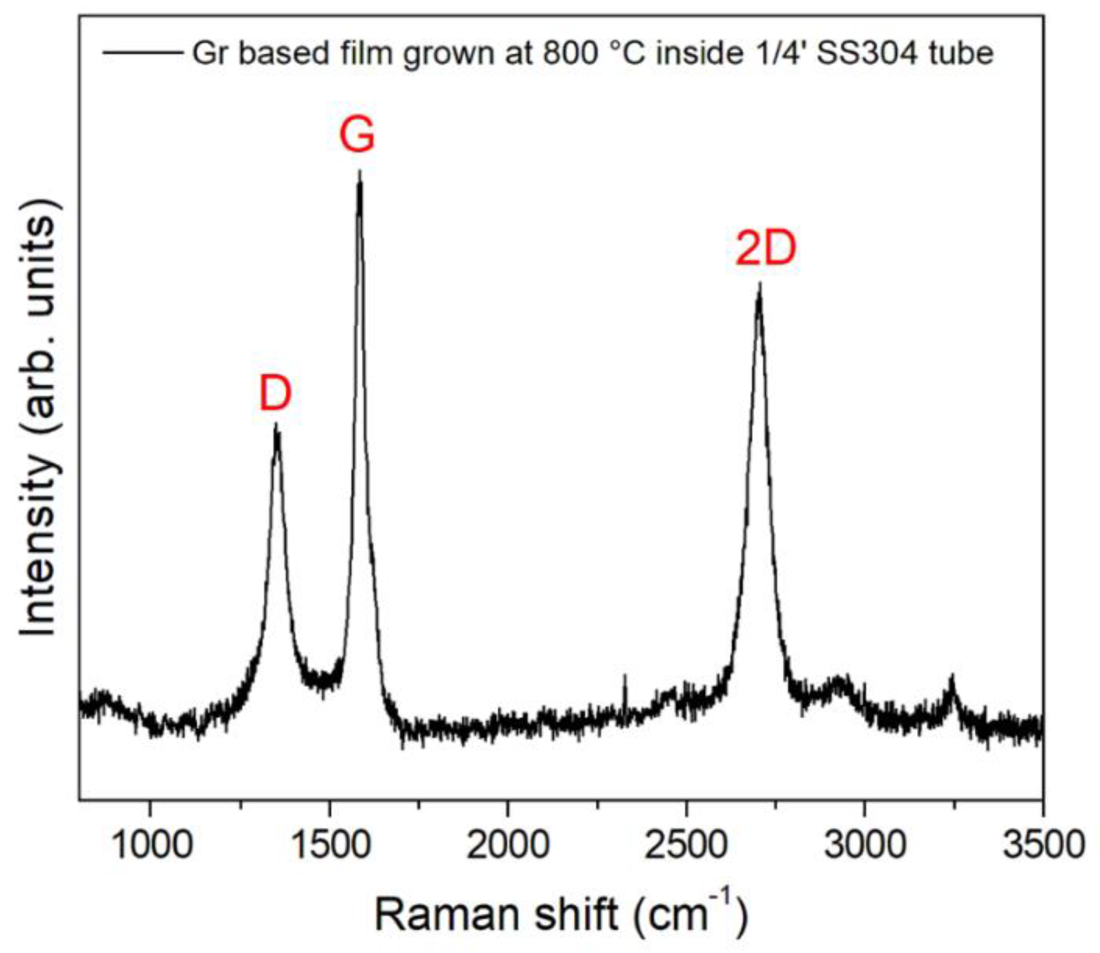
Raman spectroscopy revealed another noteworthy characteristic of the DLC-like film deposited inside the tube: a sharp 2D peak, as illustrated in Figure 11. The D and G peaks observed are consistent with previously reported bands in our recent study [4], indicating the presence of large crystalline structures within the glassy carbon film, as noted in earlier observations.
4. Conclusions
The study reported results from diverse and previously unexplored treatment regimes (N-PIII, Ar-PIII, and acetylene-PIII) applied to small ¼” SS304 tubes using a forced gas injection method. These treatments were conducted with a straightforward tube/insulator assembly inside a 30-liter vacuum chamber.
SEM inspection of the as-supplied tube's interior wall revealed a severely damaged surface characterized by islands approximately 20 μm in size with visible cracks, rendering it unsuitable for applications requiring a high level of cleanliness. EDX analysis indicated a high carbon content, possibly retained during the acetone ultrasonic cleaning process, alongside a low oxygen concentration.
Ar-PIII, or Argon plasma cleaning, appeared to mitigate surface irregularities to some extent; however, high-energy Ar ion sputtering led to a surface marked by pits approximately 20 μm in size. EDX analysis of the treated surface revealed a substantial increase in oxygen content and a significant reduction in carbon levels. The higher oxygen concentration is likely attributable to water contamination, while the reduction in carbon suggests its removal during the treatment process. Additionally, a slight improvement in hardness was observed on both the interior and exterior surfaces of the tube, consistent with the presence of plasma on both sides during the treatment.
When N-PIII was applied to the tube interior following a short Ar-PIII treatment, the surface became significantly smoother, with a substantial reduction in carbon content and an increase in oxygen concentration. However, no noticeable improvement in hardness was observed in this case.
It can be concluded that Ar-PIII effectively mitigates, to some extent, the high surface roughness and molecular trapping inherent to the as-received SS304 tube. The addition of N-PIII further enhanced the smoothness of the internal tube wall, resulting in superior quality surfaces suitable for applications requiring high cleanliness.
DBD plasma was also activated under specific operating conditions in the setup, as evidenced by the emission of light from the Macor dielectric insulator, indicating plasma presence. The dielectric temperature increased rapidly, and mixed discharges of DBD and HC plasmas were observed under certain conditions. These mixed discharges may be useful for applications beyond those discussed here, such as exploring DBD + HC discharges for other purposes.
By disconnecting the gas injection system from the tube, a faint plasma glow discharge formed inside the ¼” diameter tube, while a stronger plasma was observed outside the tube. This suggests that external treatment of the tube can also be effectively achieved using this approach. The plasma escaping from the tube mouth could potentially be utilized for other applications, such as plasma torch treatments for large surface industrial components via surface scanning. Depending on the pulsing conditions, long plasma plumes can be generated, further extending the potential uses of this method.
Glassy carbon (GC) coatings were successfully deposited on the interior of the ¼” tube using high-temperature acetylene PIII&D. Film thicknesses exceeding 340 μm were achieved within one hour; however, delamination occurred upon separating the treated tube section. Efforts are ongoing to improve the adhesion of these thick glassy carbon coatings to the internal tube walls and to achieve even thicker, more durable coatings..
Author Contributions
A.R.M., M.U., F.I.M. and S.F.M.M. conceived the work, developed the theory methodology, and performed the investigation and computations. M.U. and A.R.M. wrote the original draft preparation. A.R.M. wrote the review and editing. F.I.M. and S.F.M.M performed the data analysis. G.B.S performed the analytical investigation and computations. C.B.M. and R.M.O provided supervision and final revision
Funding
This research was funded by Ministério da Ciência, tecnologia e Inovação (MCTI) and Conselho Nacional de Desenvolvimento Científico e Tecnológico (CNPq).
Institutional Review Board Statement
Not applicable.
Informed Consent Statement
Not applicable.
Data Availability Statement
The authors declare data will be available upon request.
Conflicts of Interest
The authors declare no conflicts of interest.
References
- Lioce, D., Orlandi, S., Moteleb, M., Ciampichetti, A., Afzali, L., Ghirelli, N. & Petrov, A. ITER tokamak cooling water system design status. Fusion Science and Technology, 2019, 75(8), 841-848. [CrossRef]
- Pinedo, C. E., & Monteiro, W. A. Surface hardening by plasma nitriding on high chromium alloy steel. Journal of materials science letters, 2001, 20(2), 147-150. [CrossRef]
- Conrad, J. R., Radtke, J. L., Dodd, R. A., Worzala, F. J., & Tran, N. C. Plasma source ion-implantation technique for surface modification of materials. Journal of Applied Physics, 1987, 62(11), 4591-4596. [CrossRef]
- Mariano, S. F. M., & Ueda, M. Glass-like carbon films grown by pulsed hollow cathode via plasma immersion ion implantation and deposition. Thin Solid Films, 2020, 693, 137703. [CrossRef]
- Lv, Y. G., Wang, Y. T., Meng, T., Wang, Q. W., & Chu, W. X. Review on thermal management technologies for electronics in spacecraft environment. Energy Storage and Saving, 2024, 3(3), 153-189. [CrossRef]
- Kostov, K. G., Nishime, T. M. C., Castro, A. H. R., Toth, A., & Hein, L. R. D. O. Surface modification of polymeric materials by cold atmospheric plasma jet. Applied Surface Science, 2014, 314, 367-375. [CrossRef]
- Ueda, M., Kostov, K. G., de Moraes Oliveira, R., da Silva Savonov, G., Mello, C. B., & Fernandes, B. B. Biased Atmospheric, Sub-Atmospheric, and Low-Pressure Air Plasmas for Material Surface Improvements. IEEE Transactions on Plasma Science, 2011, 39(10), 1998-2005. [CrossRef]
- ResearchGate. Available online: https://www.researchgate.net/publication/330542354. (accessed on the 13th of November, 2024). No DOI is available.
- Sakudo, A., Yagyu, Y., & Onodera, T. Disinfection and sterilization using plasma technology: Fundamentals and future perspectives for biological applications. International journal of molecular sciences, 2019, 20(20), 5216. [CrossRef]
- Oliveira, R. M., Oliveira, A. C., Carreri, F. C., Gomes, G. F., Ueda, M., Silva, M. M. N. F., L. Pichon & Tóth, A. Detailed surface analyses and improved mechanical and tribological properties of niobium treated by high temperature nitrogen plasma based ion implantation. Applied Surface Science, 2013, 283, 382-388. [CrossRef]
- Ueda, M., Silva, C., de Souza, G. B., Pichon, L., & Reuther, H. High temperature plasma immersion ion implantation using hollow cathode discharges in small diameter metal tubes. Journal of Vacuum Science & Technology B, 2019, 37(4). [CrossRef]
- Carreri, F. C., Oliveira, R. M., Oliveira, A. C., Silva, M. M. N. F., Ueda, M., Silva, M. M., & Pichon, L. Phase formation and mechanical/tribological modification induced by nitrogen high temperature plasma based ion implantation into molybdenum. Applied surface science, 2014, 310, 305-310. [CrossRef]
- RUP-6 data sheet from GBS Elektronik, GmbH. https://www.gbs-elektronik.de/media/download_gallery/Rup6-12CLv2e.pdf.
- WILEY Online Library. Available online: https://onlinelibrary.wiley.com/doi/full/10.1111/j.1747-1567.2010.00618.x. (accessed on the 15th of November, 2024). [CrossRef]
Figure 1.
(a) Schematic representation of the 0.6 cmØ SS 304 substrate tube modified by PIII and PIII&D, showing details of the tube assembly within a 30-liter vacuum chamber; (b) An exploded view highlighting the tube assembly, including Macor insulation and high-voltage pulse applications.
Figure 1.
(a) Schematic representation of the 0.6 cmØ SS 304 substrate tube modified by PIII and PIII&D, showing details of the tube assembly within a 30-liter vacuum chamber; (b) An exploded view highlighting the tube assembly, including Macor insulation and high-voltage pulse applications.
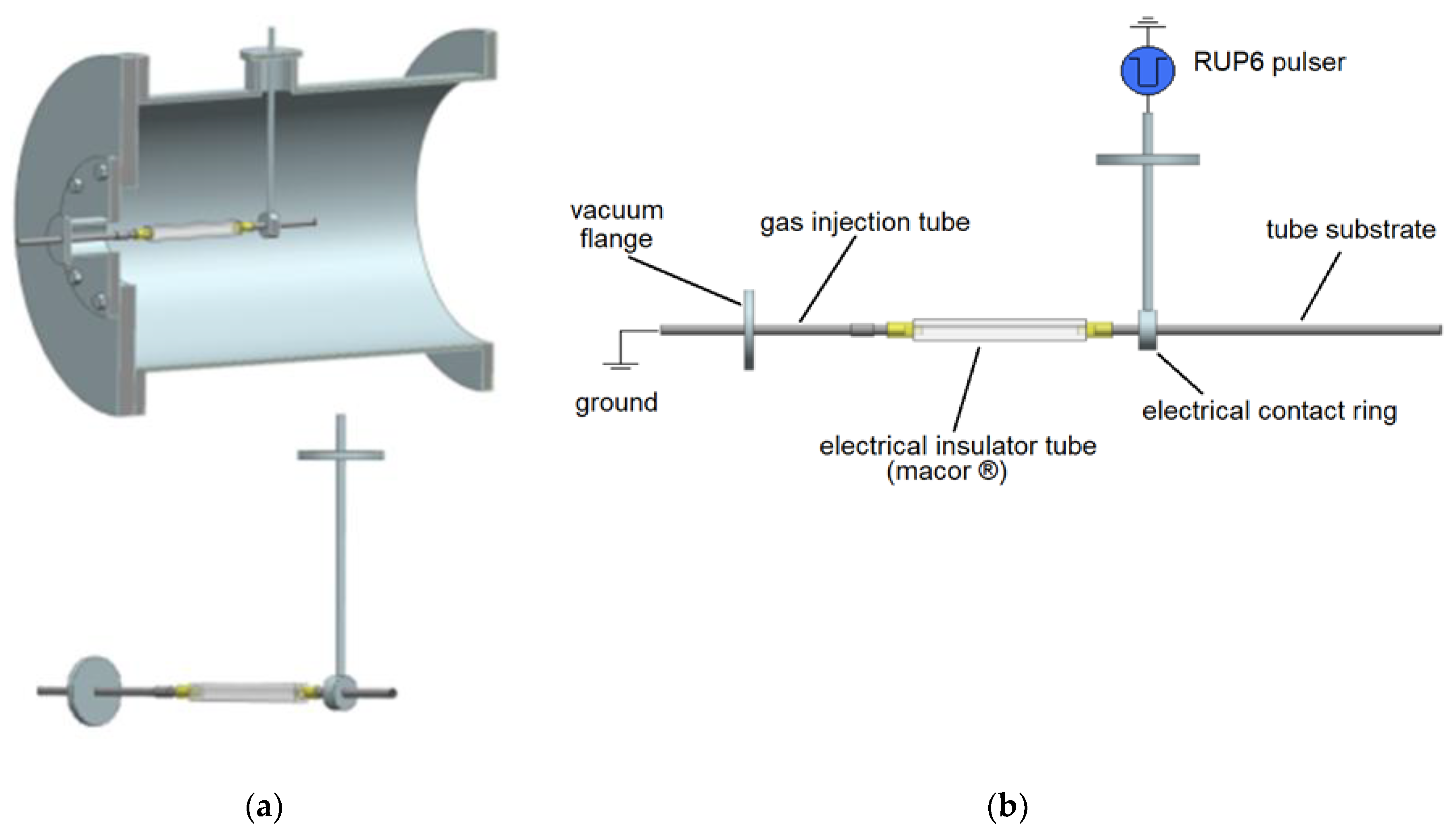
Figure 2.
Digital photo (a) of the nitrogen plasma jet expelled from the tube in the hollow cathode mode; (b) when the plasma turned-on mainly outside the tube and on its supporting structures.
Figure 2.
Digital photo (a) of the nitrogen plasma jet expelled from the tube in the hollow cathode mode; (b) when the plasma turned-on mainly outside the tube and on its supporting structures.
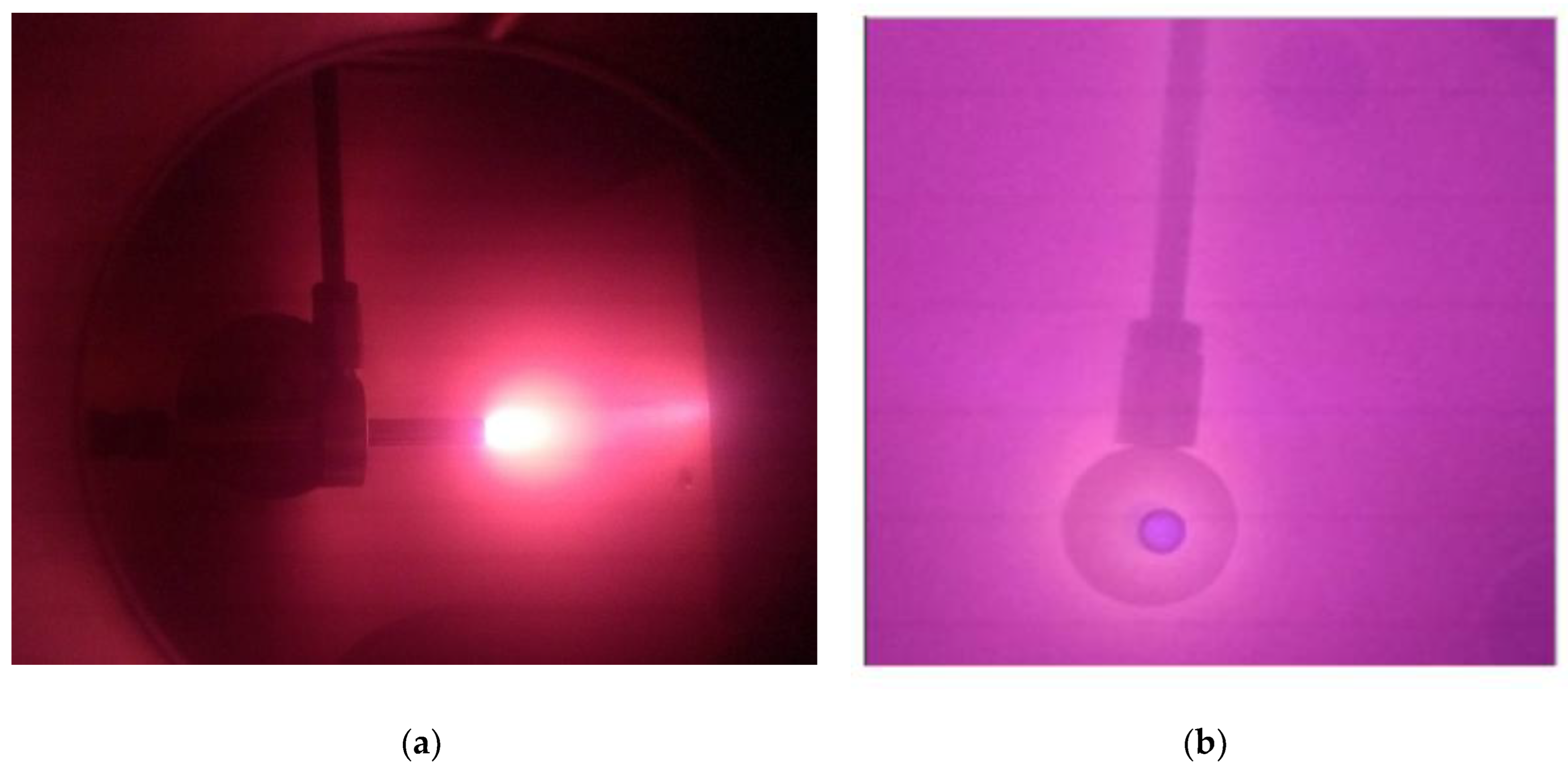
Figure 3.
Digital photograph of the as-received SS304 tube with a diameter of 0.6 cm: (a) showing two half-tubes, and (b) a closer view of one half-tube. The tube sample length is 8 cm.
Figure 3.
Digital photograph of the as-received SS304 tube with a diameter of 0.6 cm: (a) showing two half-tubes, and (b) a closer view of one half-tube. The tube sample length is 8 cm.
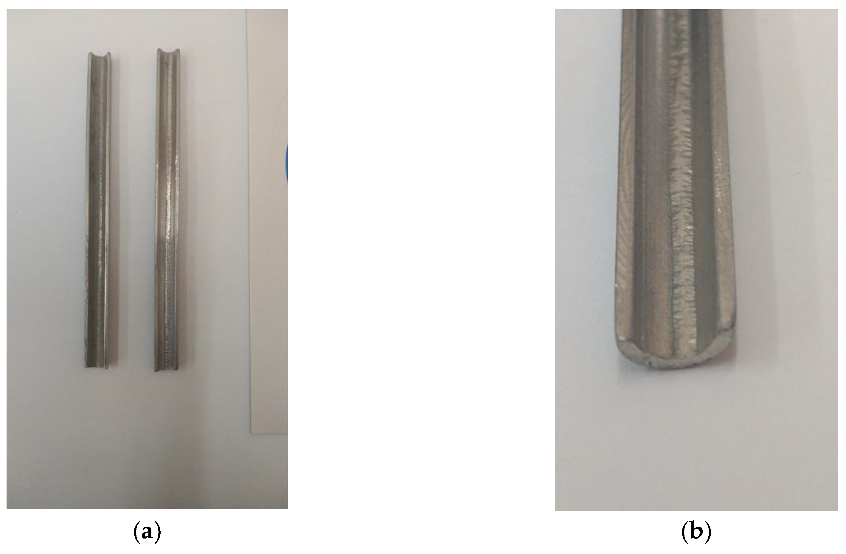
Figure 4.
SEM images of the interior of the as-received ¼” tube: (a) 2 kx ; (b) 5 kx.
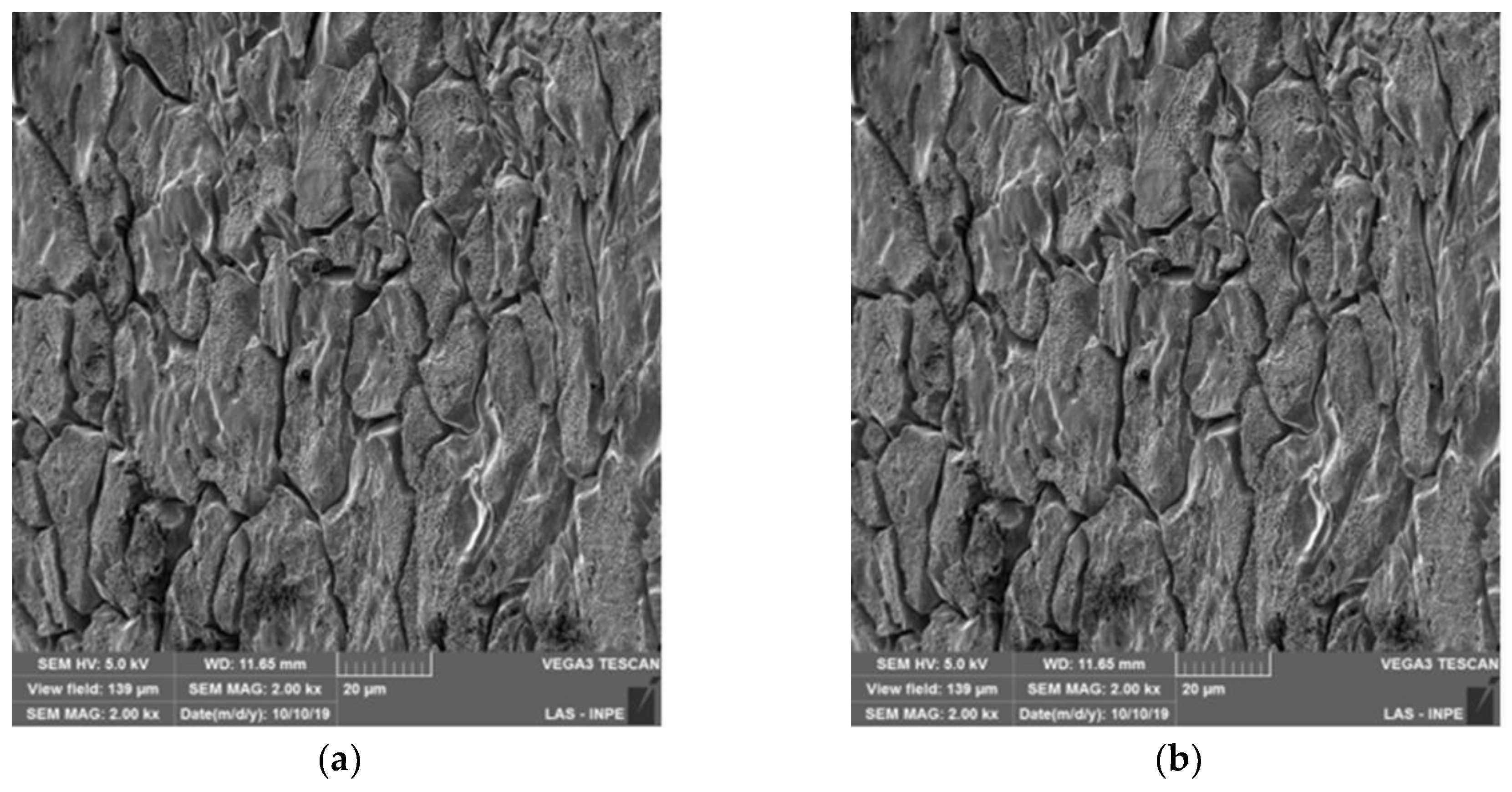
Figure 5.
EDX elemental analysis and their concentrations in At %, for the as received tube.
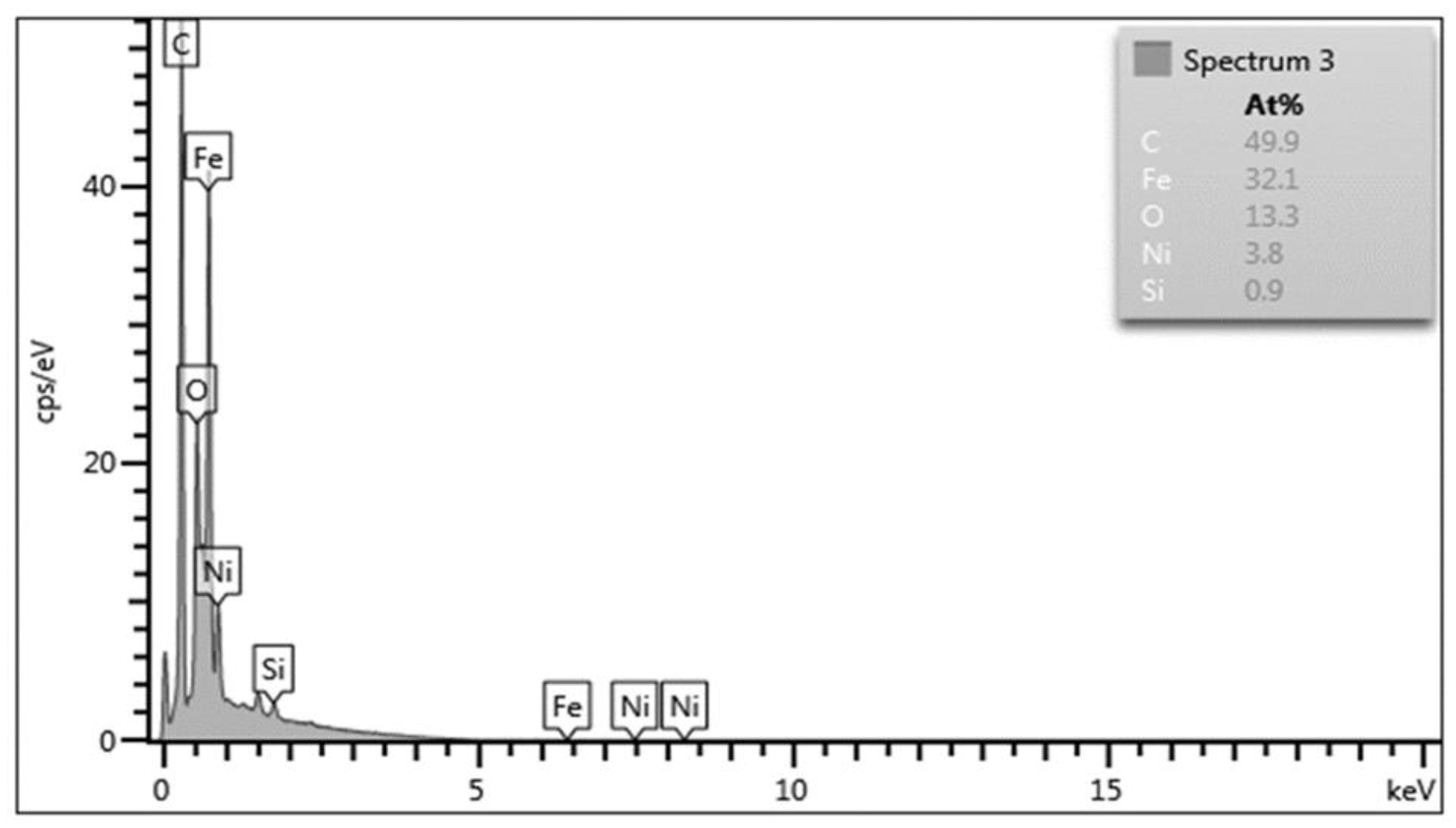
Figure 6.
SEM images of the interior of the Ar-PIII treated ¼” tube: (a) 1 kx ; (b) 2 kx.
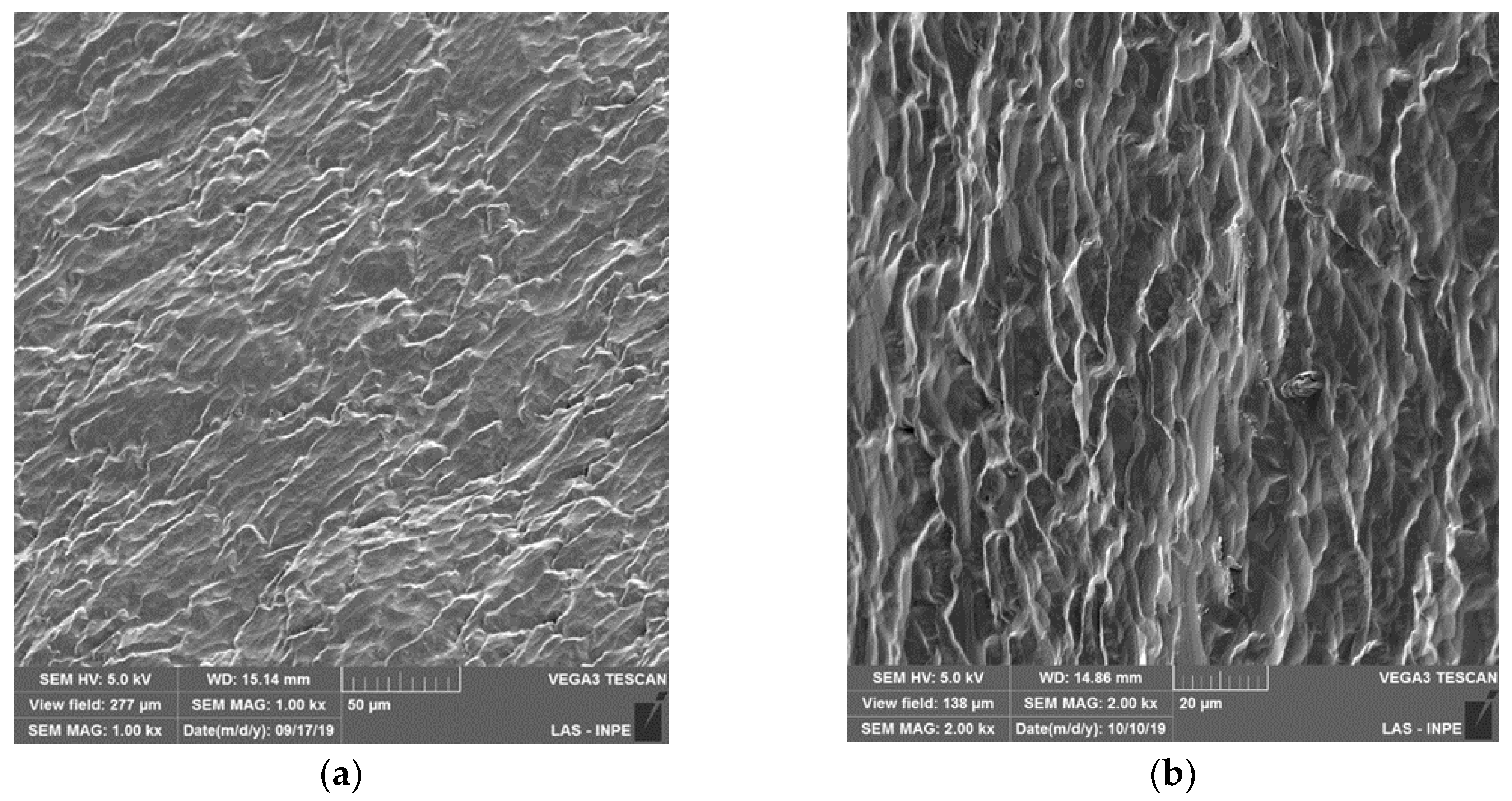
Figure 7.
EDX elemental analysis and corresponding concentrations in At %, for the tube after Ar-PIII.
Figure 7.
EDX elemental analysis and corresponding concentrations in At %, for the tube after Ar-PIII.
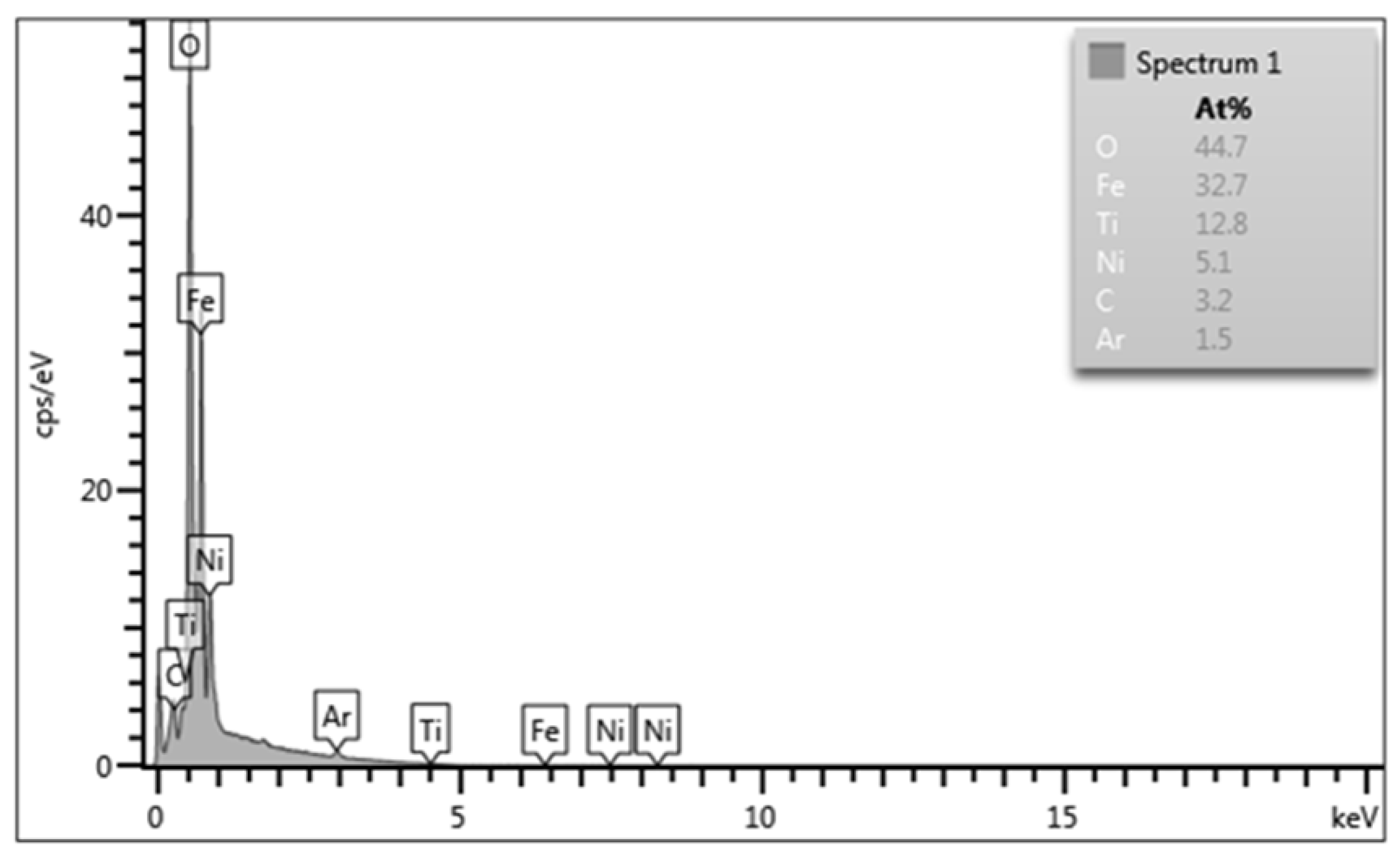
Figure 8.
Hardness profile for the tube section after Ar-PIII.
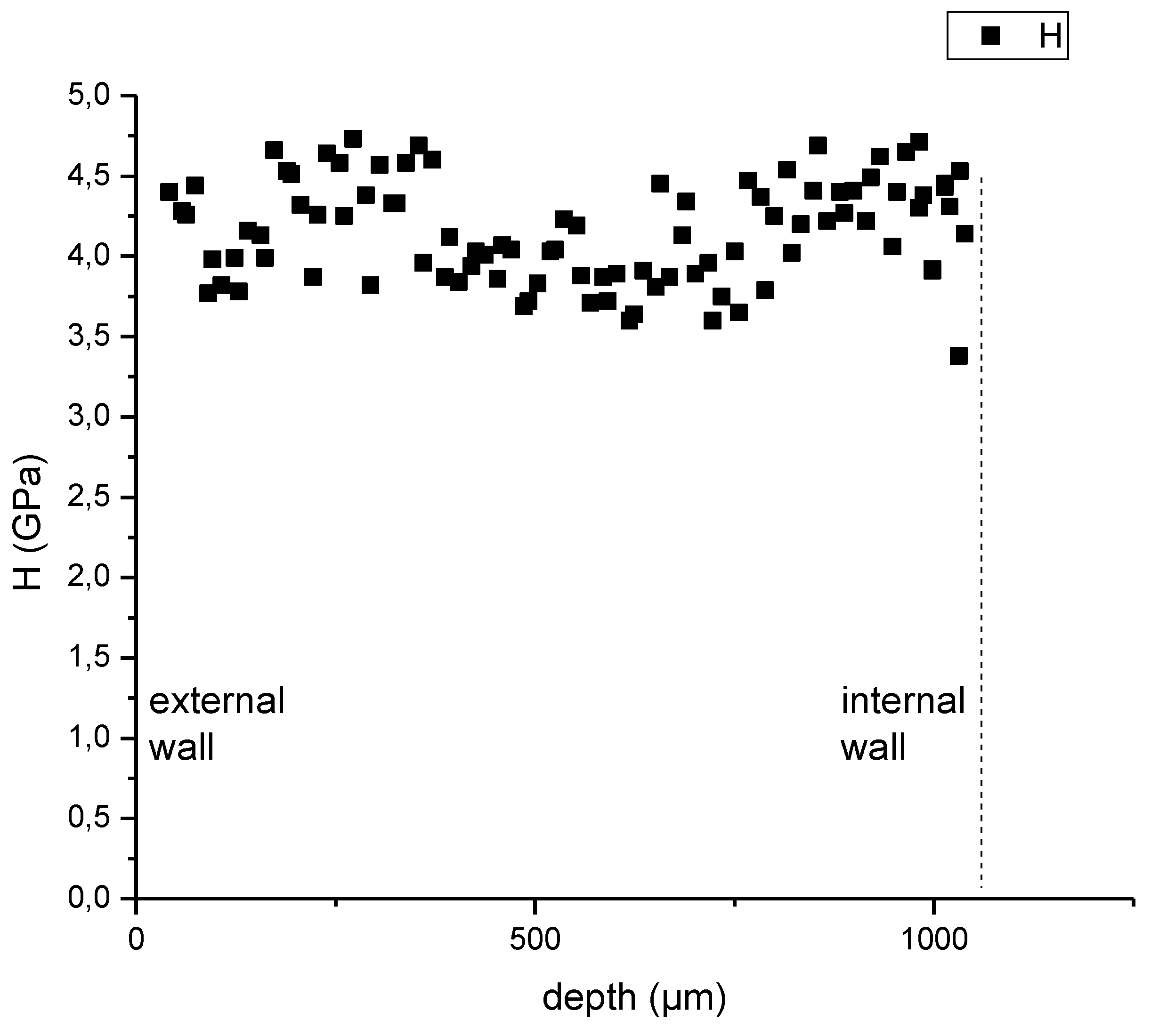
Figure 9.
SEM images of the interior of the N-PIII treated ¼” tube: (a) 1 kx ; (b) 2 kx.
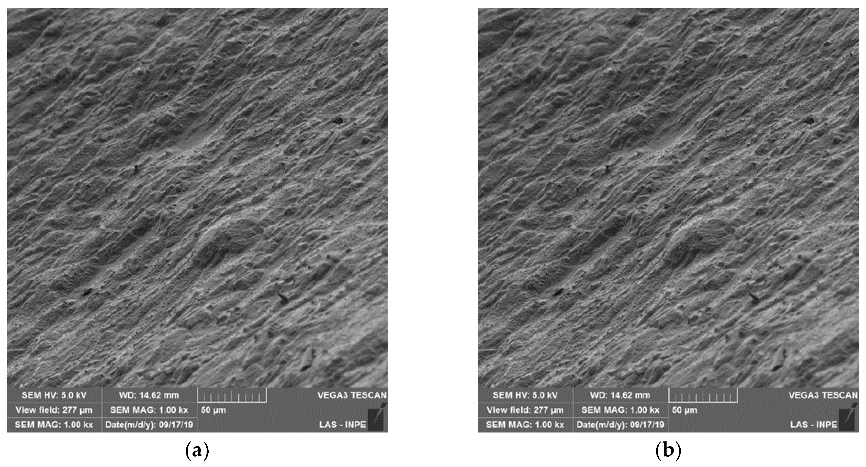
Figure 10.
FEG-SEM images of the interior surface of the acetylene-PIII treated ¼” tube: (a) an image showing a uniform portion of the DLC-like deposited film; (b) a region with exceptionally thick film deposition inside the treated tube.
Figure 10.
FEG-SEM images of the interior surface of the acetylene-PIII treated ¼” tube: (a) an image showing a uniform portion of the DLC-like deposited film; (b) a region with exceptionally thick film deposition inside the treated tube.
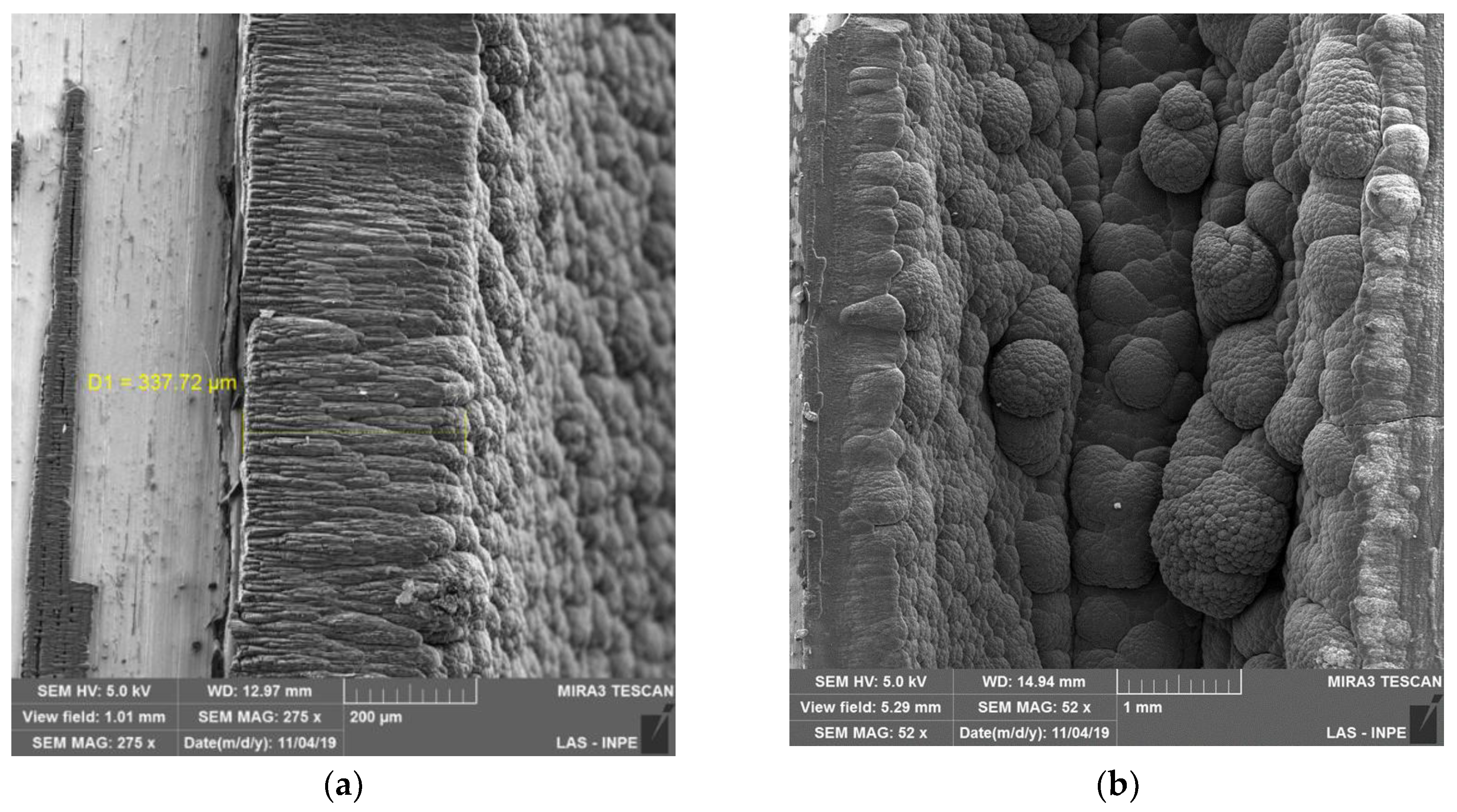
Figure 11.
Raman Spectra of detached film from the tube, after acetylene PIII&D for 1 h.
Disclaimer/Publisher’s Note: The statements, opinions and data contained in all publications are solely those of the individual author(s) and contributor(s) and not of MDPI and/or the editor(s). MDPI and/or the editor(s) disclaim responsibility for any injury to people or property resulting from any ideas, methods, instructions or products referred to in the content. |
© 2025 by the authors. Licensee MDPI, Basel, Switzerland. This article is an open access article distributed under the terms and conditions of the Creative Commons Attribution (CC BY) license (http://creativecommons.org/licenses/by/4.0/).
Copyright: This open access article is published under a Creative Commons CC BY 4.0 license, which permit the free download, distribution, and reuse, provided that the author and preprint are cited in any reuse.


