Preprint
Article

This version is not peer-reviewed.

Analysis of Mechanical Properties SCR420 Low Alloy Steel According to Heat Treatment Before Cold Forging

A peer-reviewed article of this preprint also exists.

Submitted:

24 February 2025

Posted:

25 February 2025

You are already at the latest version

Abstract

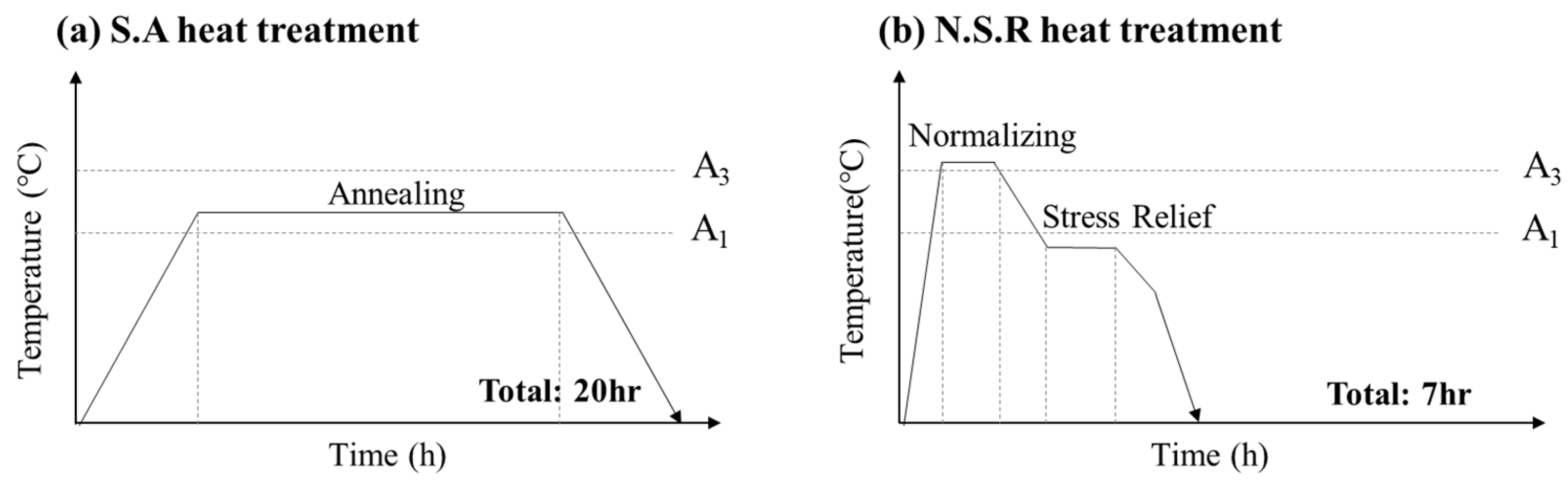
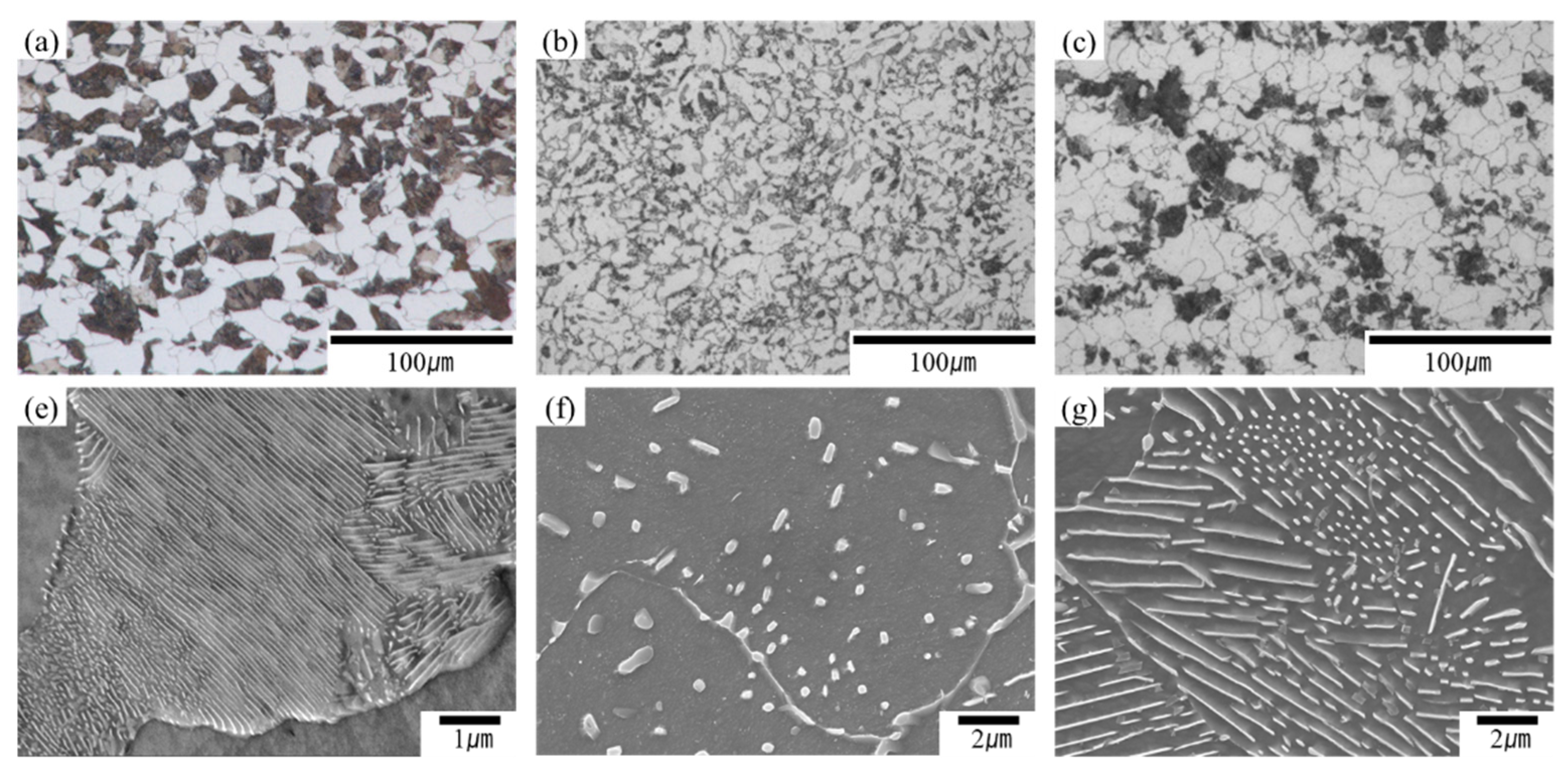
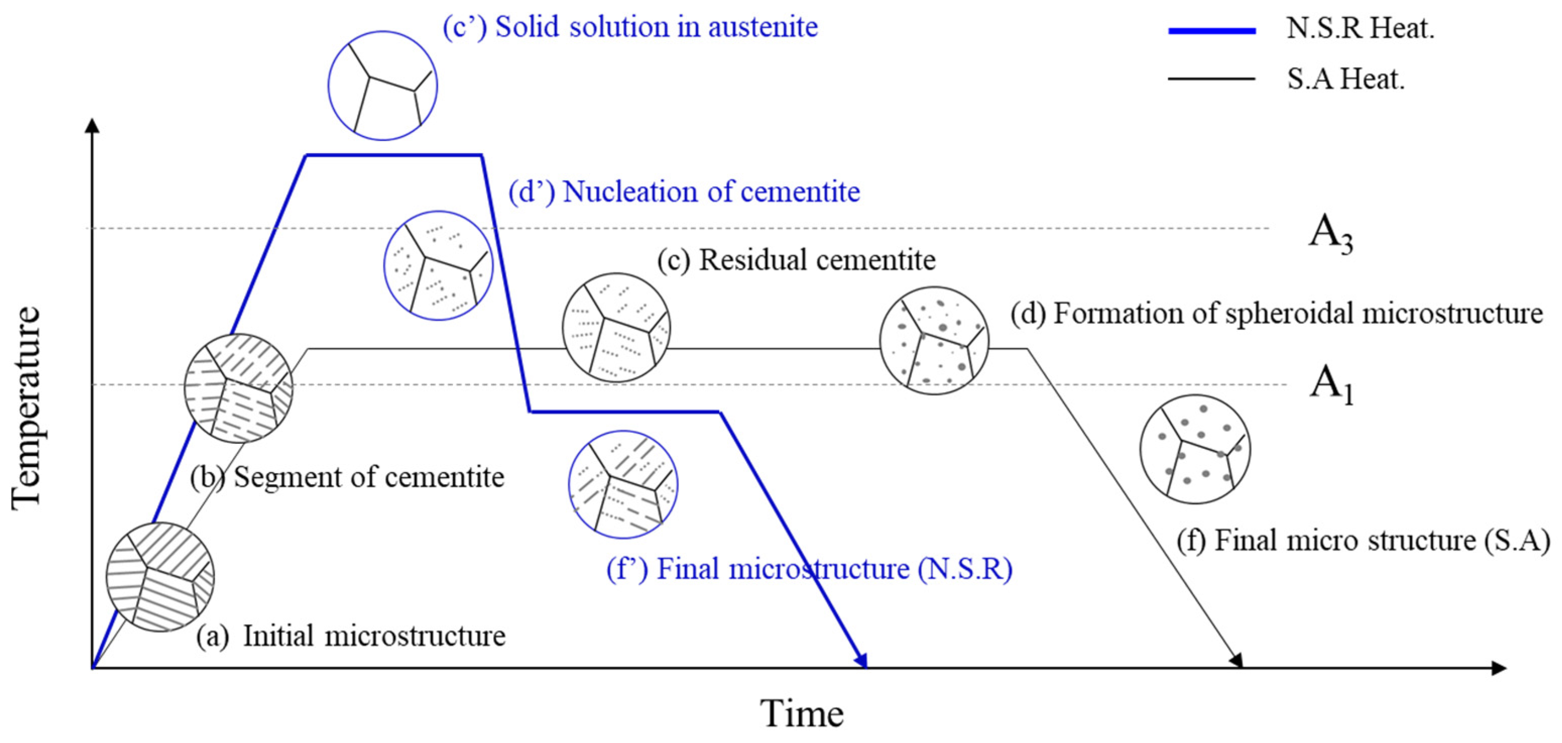
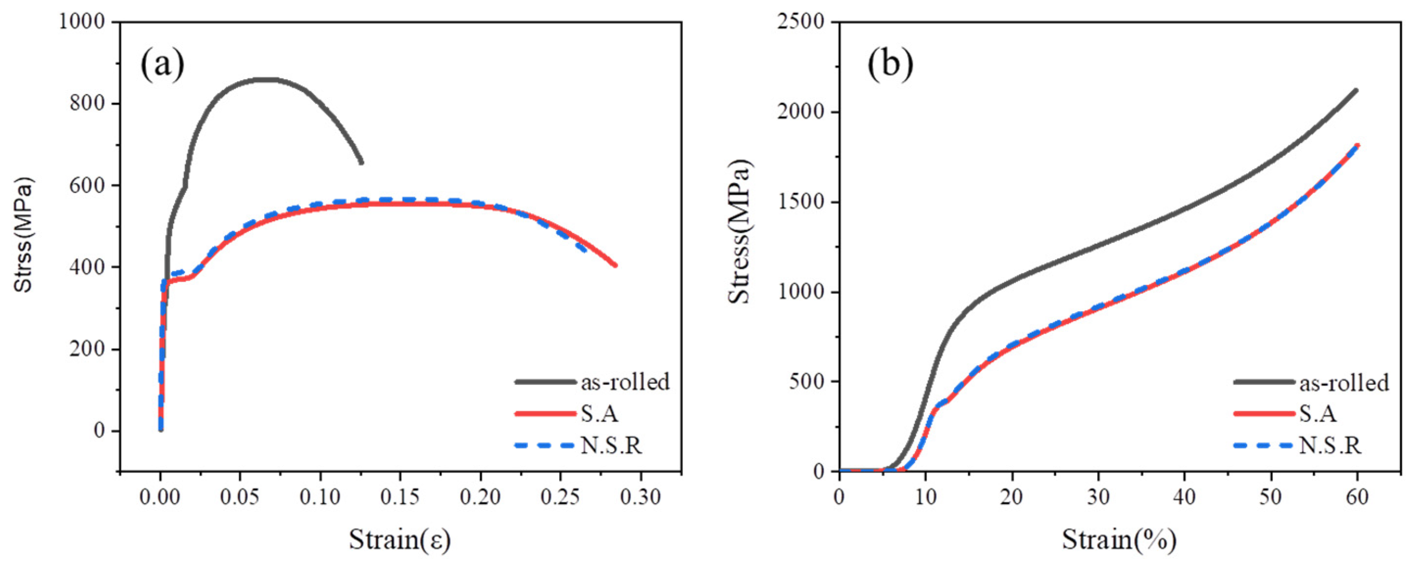
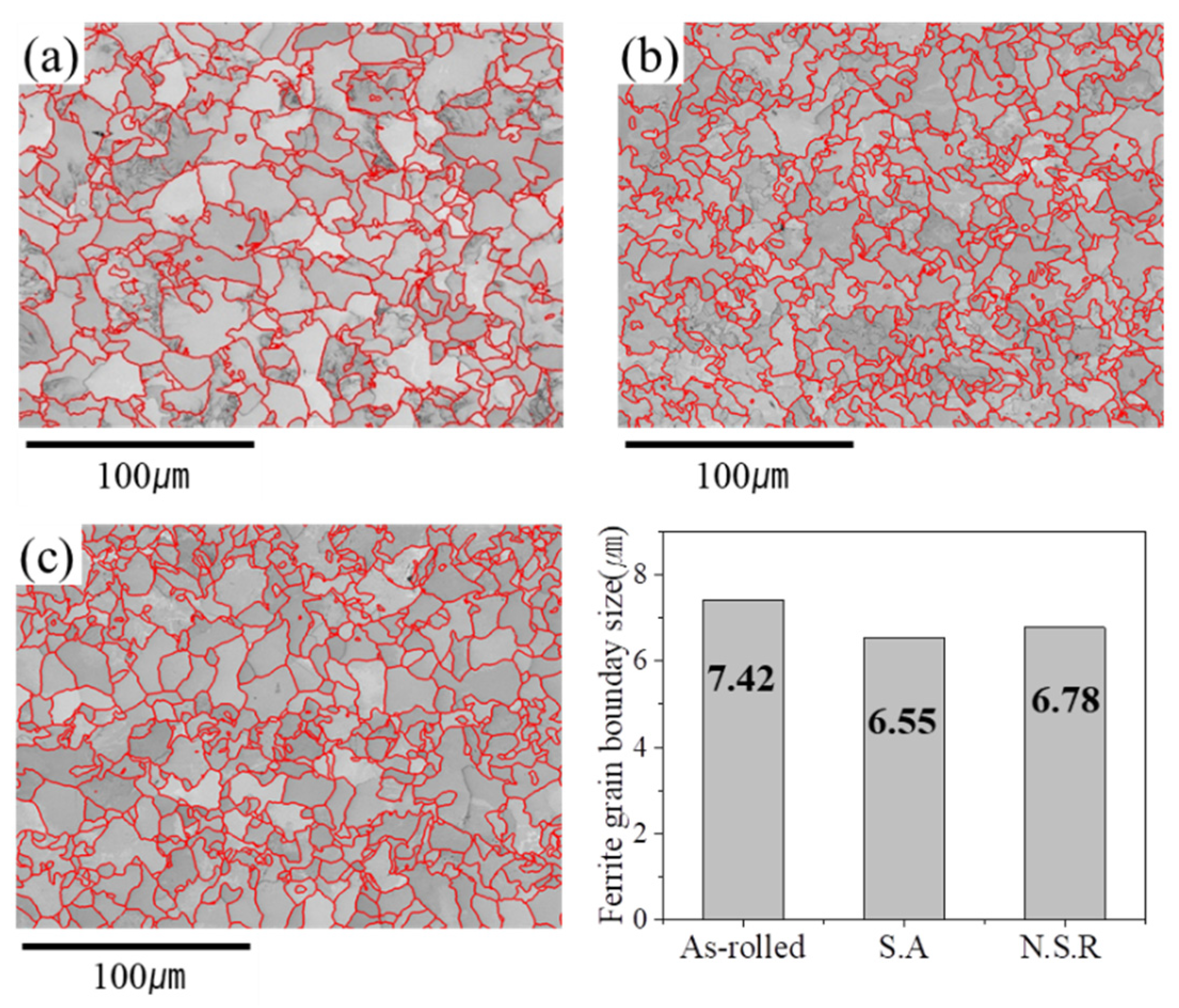
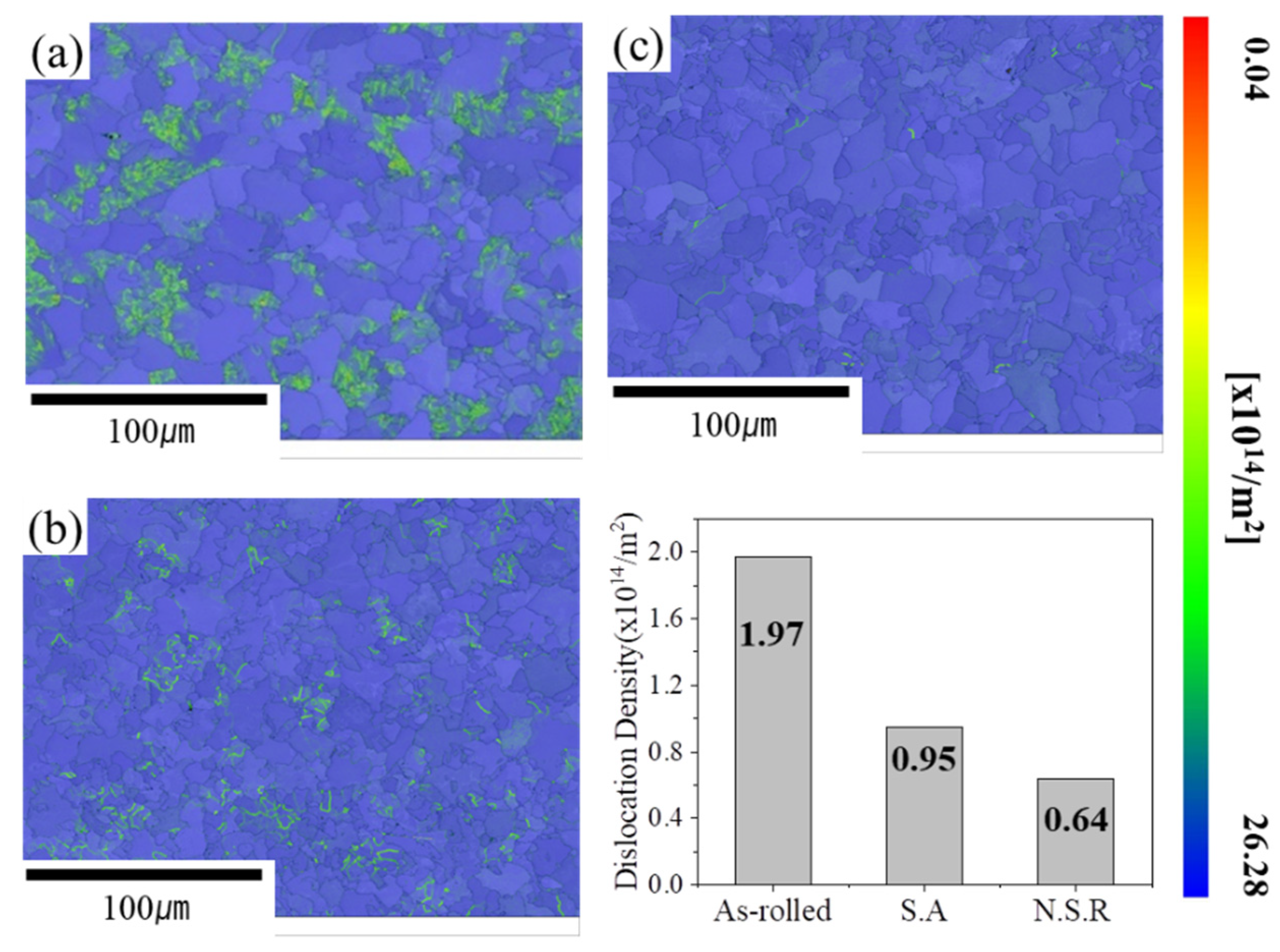
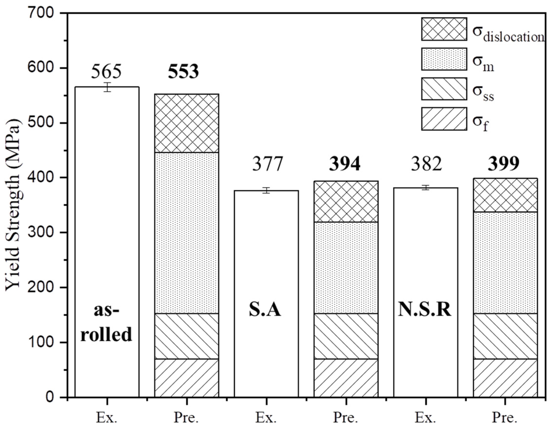
This study developed a new heat treatment method, normalizing & stress relief (N.S.R), to increase productivity compared to spheroidizing annealing (S.A). The influence of different microstructures resulting from these heat treatments was investigated in cold-forged steel. Despite a shorter heat treatment time, the mechanical properties of the N.S.R alloy were found to be similar to those of the S.A alloy. The factors influencing the mechanical properties of the experimental alloys were analyzed using the Hall-Petch equation, and the predicted values closely matched the measured strength of hy-per-eutectoid steels. The primary factors affecting mechanical properties were micro-structure and dislocation density. In the case of the S.A alloy, the microstructure exhibited lower strength due to the spherical cementite structure. In contrast, the N.S.R alloy had lower strength because of a reduced dislocation density. This was achieved by stress-relief heat treatment below the A1 temperature after phase transformation. Based on the mechanical properties, cold forging simulations showed that the effective stress during cold forging of the N.S.R alloy was similar to that of the S.A alloy.

Keywords: 
;  ;  ;  ;  

1. Introduction

In response to global warming, the Paris Agreement to keep the temperature increase to well below 2°C above pre-industrial levels came into force in 2016. In response, major countries around the world are introducing carbon border taxes and adopting net-zero policies, where the sum of carbon savings and emissions is zero in 2050 [1]. As a result, the automotive industry is making various attempts to comply with greenhouse gas reduction policies [2,3,4]. In particular, in the field of automotive drive components, forging and heat treatment processes are being changed to improve material recovery and reduce carbon emissions. Forging is the process of manufacturing automotive parts by applying heat and pressure to a metal to plastically deform it. Depending on the temperature, forging is categorized into hot forging and cold forging. [5,6]. Hot forging heats the workpiece above its recrystallization temperature, resulting in excellent formability and productivity. However, it has disadvantages such as thermal cracking, poor dimensional accuracy, and surface quality [7].
On the other hand, clod forging is a forging process that takes place at room temperature, so the dimensional accuracy of the alloy is very good. However, the material must be heat treated before forging to ensure ductility [8]. In particular, the cold forging process is carried out after forming a ductile microstructure because a large deformations occur at room temperature at a high rate during forging. However, S.A, which improves cold forging, requires a long time at A1 temperature or higher to obtain ductility of the material, so it is not efficient in terms of forging productivity and emitting a large amount of CO2 gas [9,10,11].
In this study, we proposed a new N.S.R eco-friendly heat treatment process that can effectively shorten the heat treatment time while maintaining the same mechanical properties as S.A heat treated materials. To confirm the effectiveness of N.S.R. heat treatment, the test alloy was selected SCR420 steel, which is widely used in automotive parts, and the microstructure analysis and mechanical properties were compared according to the heat treatment method [12].
The Hall-petch model was used to investigate why the mechanical properties of S.A and N.S.R alloys are similar despite the reduced heat treatment time. The effective stresses in cold forging of S.A. and N.S.R. heat treatments were also compared using by AFDEX, a finite element analysis software for plastic processing.

2. Materials and Methods

2.1. Development of N.S.R Heat Treat Ment

In industry, spheroidizing annealing to achieve ductility in materials are typically held near A1 temperature for at least 20 hours and then cooled [9,13,14]. This heat treatment is difficult to secure productivity and emits a lot of CO2 gas, so it needs to be improved from a long-term perspective. In this study, we developed a new heat treatment method (N.S.R) that can compensate for the shortcomings of spheroidizing annealing, and the schematic diagram of the heat treatment is shown in Figure 1.
N.S.R heat treatment is a heat treatment method that applies a combination of normalizing and stress relief heat treatment, and the heat treatment time is shortened to 7 hours by controlling the heat treatment temperature and cooling rate. In order to improve the strength and microstructure homogenization of the alloy, it was cooled to below A1 temperature after maintaining a certain time in the austenite region above A3 temperature. The alloy was then heat treated and annealed below A1 temperature to minimize the residual stresses generated during the phase transformation from γ(austenite) → α(ferrite) + θ(cementite).
N.S.R improves productivity by about 70% compared to conventional S.A. heat treatment, which can significantly reduce manufacturing costs and carbon emissions. In this study, S.A and N.S.R heat treatments were performed based on SCR420 material with the composition as shown in Table 1. The SCR420 material utilized in this study is Φ60 bar steel from hyundai-steel.

2.2. Microstructures and Mechanical Properties

To analyze the microstructure of the experimental alloys before and after heat treatment, the vertical cut surfaces of the Φ60 rolled bar and heat treated material were mechanically polished with silicon carbide paper (#100~#2000) and diamond suspension at 1μm level and etched with a 3% solution of Nital. Microstructural analysis measurements were analyzed using an OM (Olympus Gx51), SEM-EDS (JEOL, 7100F) microscope. The ferrite fraction was measured according to ASTM E562, and the remaining volume fraction other than the measured ferrite fraction was considered as pearlite.
The cementite spacing of the experimental alloys was measured by applying the mean free path (MFP) method. For quantitative analysis of MFP, at least 10 SEM photographs at ×20,000 magnification were taken for each condition. Based on this, the mean random spacing obtained was divided by 2 to obtain the mean true spacing as shown in Eq. (1) [15].
S r = 3.14   ·   D 2 n
Where Sr is the average distance between cementites, D is the diameter of the measurement area, and n is the number of cementites measured in that area. Grain size and dislocation density were measured using EBSD (Oxford Symmetry) mounted on the FE-SEM. Grain size was measured at a magnification of x500, step size of 0.2 μm, tilt of 0%, and accelerating voltage of 20 kV. Dislocation density was measured at x1000 magnification, step size 0.2 μm, slope 80%, and acceleration voltage 20 kV.
To evaluate of the mechanical properties of S.A and N.S.R alloys, samples were taken from the 1/4 point of the cross-section of the Φ60 bar and evaluated in tensile and compression tests at room temperature. The tensile specimens were evaluated using a tensile testing machine (Zwick/Roell, Z250) using a proportional test specimen, KS 14A (diameter 6 mm, marking distance 30 mm). The tensile test was performed at 0.009㎜/s up to yield and 0.241mm/sec during tension.
The compression test was performed using a compression tester (Zwick/Roell, Z600) with a 15 mm compression specimen of Ø10. The compression test was performed at a speed of 3.3 mm/s to compress the specimen to 60% of its cross-sectional area.

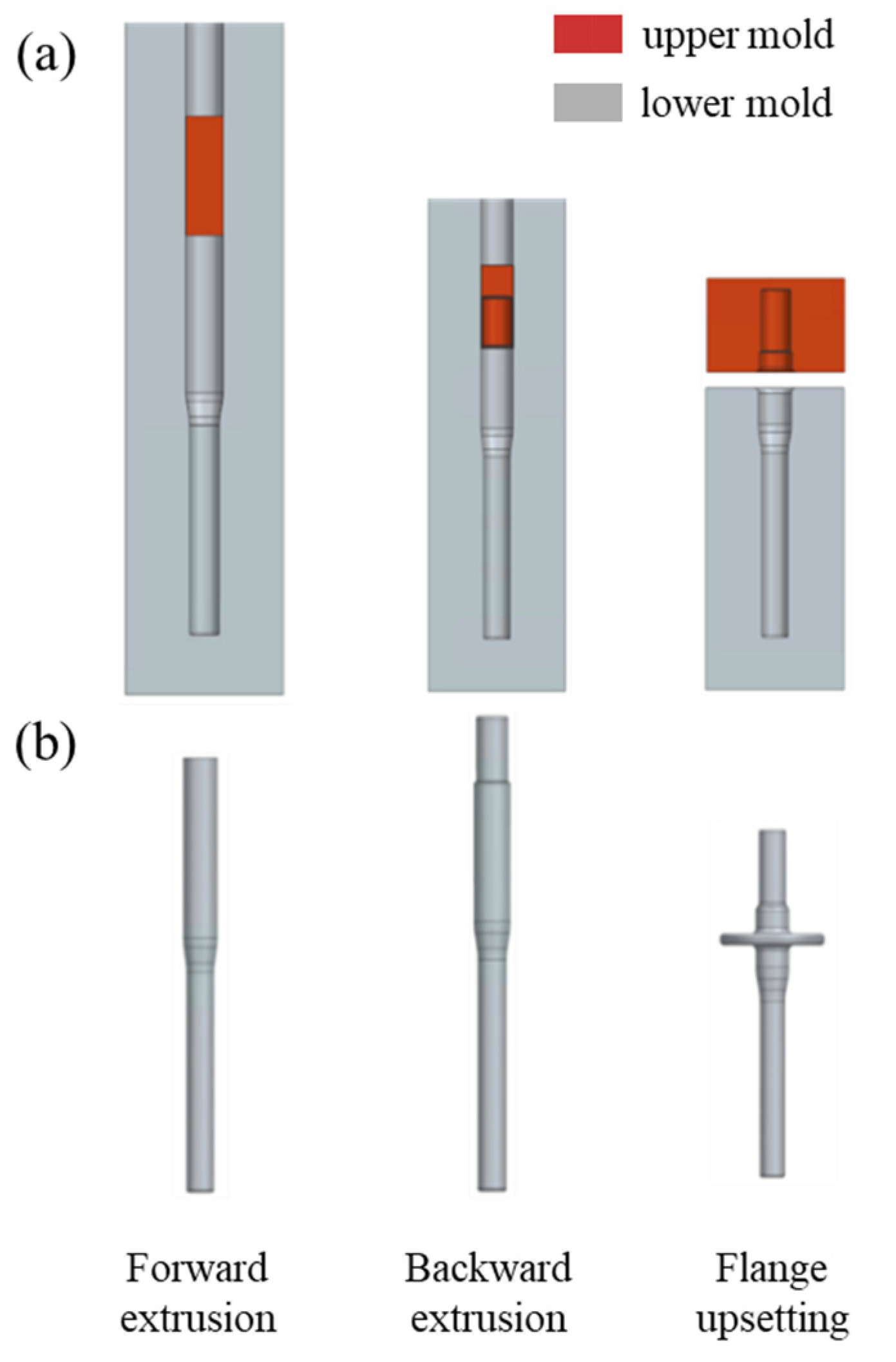
2.3. Analysis of Cold Forging Formability

In order to validate the cold forging process of N.S.R alloy, a commercial forging analysis was conducted on the input shaft, an automotive drive part. The input shaft cold forging process consists of three processes: forward extrusion, backward extrusion, and flange upsetting, and the molds and models for each process are shown in Figure 2.
The finite element model of the input shaft is made of SCR420 Φ60 bar steel cut into 300 mm length, and the molds of each process are modeled at a 1:1 scale and meshed with Tetrahedral Brick Element. AFDEX, a commercial forging finite element analysis software, was then used to analyze the forming of each process. Stress-strain curves for the cold forgeability evaluation of S.A and N.S.R alloys were based on room temperature tensile test results. In addition, young's modulus, poisson's ratio, density, and thermal expansion coefficient were calculated by J mat. pro, a thermodynamic simulation program, and their properties are shown in Table 2.
To avoid direct friction between the mold and the workpiece during cold forging, a phosphating coating treatment is applied to the workpiece, and the Coulomb friction coefficient between the forging mold and the workpiece is set at 0.1, and elastic deformation analysis is performed [16].

3. Results and Discussion

3.1. Microstructures and Mechanical Properites

Figure 3 shows microstructure measurements of as-rolled and heat-treated steels. Figure 3a shows the microstructure of the as-rolled material of SCR420 steel grade, which has a mixed ferrite and pearlite microstructure. In addition, Figure 3. (e) shows the micrograph of pearlite at ×30,000 magnification and confirms that it has a fine lamella structure of cementite.
S.A alloy exhibited a typical spherical cementite texture as shown in Figure 3b [17]. As shown in the schematic diagram in Figure 4, S.A heat treatment causes the layered cementite in the pearlite to segment above the initial A1 temperature. Then, with prolonged heat treatment, some of the carbons are dissolved and residual cementite remains. In the subsequent heat treatment and cooling stages, the undissolved residual cementite acts as a nucleation site to grow spherical cementite [11,18]. On the other hand, the microstructure of N.S.R. heat-treated alloy has a mixed organization of layered and spherical cementite as shown in Figure 3g. This is because the cementite dissolved at A3 and above grows into spherical cementite as it is cooled to below A1 temperature, and the growth of cementite as it is maintained at temperatures below A1 results in a mixed lamellar and spherical microstructure.
The ferrite fraction of the experimental alloys was measured base on the as-rolled and heat treatment conditions. The ferrite fraction was measured to be 55% for the as-rolled condition, 80% S.A and 74% N.S.R, respectively. The main reason for the difference in ferrite fraction between as-rolled and heat-treated methods is the cooling rate and cooling start temperature.
Slower cooling rates increase the fraction of ferrite, while faster cooling rates increase the fraction of pearlite. This is due to the shortening of the shorter distance that the dissolved carbon atoms in the austenite can travel [18]. In other words, the accumulation of carbon concentration at the austenite/ferrite interface makes it easier to form pearlite at high temperatures, and the interlamellar distance of cementite becomes smaller. In general, the cooling rate of Φ60 bar steel after rolling is measured to be about 0.5~1℃/s for air cooling and about 0.1℃/s for furnace cooling. Therefore, the pearlite fraction of as-rolled with the fastest cooling rate is the highest.
In addition, when the cooling start temperature is lower than A3, as in S.A. heat treatment, austenite and cementite coexist in the region, so the shape of cementite is affected by the heat treatment temperature [11,13]. Therefore, even if the cooling rate of S.A. alloy and N.S.R. alloy is the same at 0.1℃, the ferrite fraction is different.
The tensile and compressive strength results of the S.A and N.S.R alloys are shown in Figure 5 and Table 3, respectively.
The tensile test results showed that the yield strength of as-rolled was 565 Mpa and the ultimate tensile strength was 842 MPa. In comparison, the yield strength of S.A was 377 MPa, and the tensile strength was 556 MPa. Finally, the yield strength of N.S.R was measured at 382 MPa and the tensile strength to be 567 MPa.
In addition, the compressive strength of the as-rolled material at 60% cross-sectional area compression was measured to be 2,119 MPa, while the compressive strengths of the S.A and N.S.R heat-treated alloys were 1,810 MPa and 1,815 MPa, respectively. Despite the different heat treatment methods, the tensile and compressive properties were found to be similar.

3.2. On the Strength Mechanisms

In general, the mechanical properties of pearlite steels can be described by the Hall-Petch relationship as shown in Eq. (2) [19].
σ = σ o + K y   λ 1 2
Where σ is the yield strength σo is the friction stress, Ky is the Hall-petch constant and λ is the interlamellar spacing of pearlitic steels. However, it is difficult to express hypo-eutectoid steels in Eq (2), because they have a dual-phase structure of ferrite and pearlite. Therefore, various studies have been attempted to quantify the strength of steels with a dual phase of ferrite-pearlite steels as shown in Eq. (3), including those by O'Donnelly, Reuben, Baker et al. [20].
σ = σ f + K y   λ p 1 2
Where is σf the friction stress of pure ferrite, Ky is the constant, λp is the mean ferrite slip distance in the composite and λp is defined as Eq. (4). [20].
λ p = V p S r T r + V a + d a
Where Vp and Va are the pearlite and ferrite fractions, respectively, da is the ferrite grain size. Sr is the interlamellar spacing, Tr is the mean cementite thickness, expressed by Eq. (5) [21].
T r = 0.15   ·   C a r b o n w t %   ·   S r V p
Based on the above equations, this study expresses the yield strength of hypo-eutectoid steels as Eq. (6) and (7) below.
σ m = K y [ V p S r T r + V a d a ] 1 2  
σ y = σ f + Δ σ m + Δ σ s s + Δ σ d i s + Δ σ p a r t i c l e
Where σf is the ferrite strength, Δσss is the solid solution hardening, Δσdis is the dislocation hardening, and Δσparticle is the precipitation hardening. However, the experimental alloys used in this study have a very low contribution to precipitate formation, so the Δσparticle effect was excluded
Initially σf was used as σf = 70 MPa for pure Fe [22]. Ky is a material constant that varies with heat treatment conditions. Therefore, experimental values were applied, and Ky was calculated from the yield zone slopes of the experimental alloys. As shown in Table 4, Ky values for the experimental alloys were measured as: as-rolled 601 MPa/㎛1/2, S.A 411 MPa/㎛1/2, N.S.R 430MPa/㎛1/2. The as-rolled Ky values were within the typical range of 440 to 760MPa/㎛1/2 for ferrite-pearlite steels [23].
S.A and N.S.R's Ky values were found to be similar to the Ky value (420 MPa/㎛1/2) obtained from spheroidizing heat treatment in a similar carbon range studied by L. Anand’s. This phenomenon of decreasing Ky value with slower cooling rate is due to the transformation of lamellar structure cementite into spheroidal form and distribution within the grains [23,24]. Therefore, the Ky values of S.A and N.S.R alloys were lower than that of as-rolled.
The Sr of the experimental alloys was calculated using Eq. (1) to obtain the average true spacing of cementite, and Tr was calculated based on Eq. (5). Sr was respectively measured as 0.12 ㎛ for as-rolled, 3.6 ㎛ for S.A and 1.3 ㎛ for N.S.R. Tr was measured 0.01 ㎛ for as-rolled, 0.43 ㎛ for S.A, and 0.19 ㎛ for N.S.R alloys.
The average grain size has a significant influence on the strength of metallic materials because high-angle grain boundaries (HAGBs) inhibit the movement of dislocations [25,26]. da is the result of using EBSD, and the average HAGB sizes were measured as 7.42㎛ for as-rolled, 6.55㎛ for S.A, 6.75㎛ for N.S.R alloys, as shown in Figure 6.
The strength of Δσm utilizing grain size and cementite parameters, was measured to be 293 MPa for as-rolled, 167 MPa for S.A and 185 MPa for N.S.R alloys, respectively.
The strengthening mechanism for the chemical component can be explained as shown in Eq. (8) below.
Δ σ s s = 47 Si + 30 Mn + 31 Cr
K.K. Ray reported that Mn and Si increase by 30 and 47 MPa per wt%, respectively [27]. Gutierrez also reported that Cr increases by 11 and 31MPa per wt% [28].
Thus, the effect of solid solution strengthening by composition was calculated to be 82.6MPa. Another strengthening mechanism, dislocation strengthening, is expressed by Taylor's equation, Eq. (9). [26].
Δ σ d i s = α G b p
Where α is the constant (0.38), G is the shear modulus (81GPa), b is the burgers vector (2.48A), and p is the dislocation density [17,29,30].
The dislocation density of the experimental alloys was measured using Geometrically Necessary Dislocation (GND) density maps as shown in Figure 7, and the dislocation densities were measured as follows as: as-rolled 1.97 × 1014 cm2, S.A 0.95 × 1014 cm2, N.S.R 0.64 × 1014 cm2. Δσdis was calculated to be 107MPa for as-rolled, 74MPa for S.A, and 61MPa for N.S.R alloys, respectively.
The sum of the predicted and experimentally measured values for each strengthening mechanism is shown in Figure 8.
The yield strength was predicted using parameters based on the heat treatment process, and the predicted total strength was measured to be 553 MPa for as-rolled, 394 MPa for S.A, and 399 MPa for N.S.R alloys. These values are similar to the experimentally measured values, with a deviation of about △17MPa. The difference between the measured and predicted yield strengths for the S.A and N.S.R alloys was the same, at △5MPa. This indicates that the predicted values for each parameter affecting the yield strength were calculated correctly.
The difference in strength between the S.A and N.S.R alloys was △18 MPa, depending on the microstructure variables. However, the reason why N.S.R alloys exhibit similar strength to S.A materials is due to the reduction in dislocation density. Compared to as-rolled, the dislocation density of S.A and N.S.R alloys was reduced by 52% and 68%, respectively. This resulted in a 13 MPa reduction in the dislocation-induced strengthening effect of the N.S.R alloy compared to the S.A. alloy.
In general, when steel passes through the A1 eutectoid temperature, a phase transformation dislocation is formed during the γ (austenite) → α (ferrite) + θ (cementite) phase transformation.
In the case of the S.A alloy, as shown in Figure 1a, heat treatment proceeds above the A1 temperature to form austenite and spherical cementite, and the dislocations disappear. However, dislocations are generated by the newly grown pearlite during cooling [11,13].. On the other hand, in the case of the N.S.R alloy, stress relief heat treatment is carried out below the A1 temperature after the phase transformation is completed, so the dislocation strengthening effect is lowered as the dislocations disappear.
Figure 9 shows the microstructure and GND density of the as-rolled material at high magnification. The dislocation density is low in the ferrite region, while it is high in the pearlite region. These results demonstrate that dislocations are formed as a result of phase transformation.

3.3. Analysis of Cold Forging Formability

The purpose of the effective strain and stress analysis is to compare the influence of the mold in the continuous production process of automotive parts based on the heat treatment method. Figure 10 shows the results of analyzing the cold forging process of the input shaft using the mechanical properties of the experimental alloys when S.A and N.S.R heat treatments are applied, which include (a) effective strain and (b) effective stress. Both S.A. and N.S.R. alloys exhibited similar strain rates in the flange upsetting process with the highest compression ratio.
In addition, the maximum effective stress at the flange was 874 MPa for both S.A. and N.S.R alloys, with no significant difference observed in the extrusion process. Therefore, it was confirmed that the maximum stress of the N.S.R alloy during the forging process is similar to that of the S.A alloy. This similarity is attributed to the comparable mechanical properties of the two experimental alloys. Based on these results, the application of the N.S.R heat treatment method in the automotive industry is expected to exhibit cold forging properties similar to those of the S.A heat treatment.

4. Conclusions

In this study, an eco-friendly N.S.. heat treatment method with mechanical properties similar to those of the S.A heat-treated material was proposed. Changes in microstructure and mechanical properties were observed as a function of the heat treatment method. The mechanical properties were investigated using the Hall-Petch equation, and the cold workability was predicted through finite element analysis. The following conclusions were drawn:
1) N.S.R heat treatment takes 7 hours, compared to S.A heat treatment, which takes more than 20 hours, reducing the heat treatment time by approximately 65%.
2) As a result of S.A. and N.S.R heat treatment of SCR420 steel grades, the tensile strengths were 556 MPa and 567 MPa, respectively, and the strength when compressing 60% of the cross-sectional area was 1,810 MPa and 1,815 MPa, respectively, showing similar mechanical properties.
3) The yield strength of the predicted and experimental alloys was calculated using the Hall-Petch formula, and the yield strengths of the S.A and N.S.R materials showed similar values with a difference of △5 MPa. The difference between the actual yield strength and the predicted yield strength was △17 MPa, confirming the validity.
4) The morphology of cementite in SCR420 steel changed depending on the heat treatment method. In the case of as-rolled before heat treatment, the cementite has a fine lamellar structure, while in the case of the S.A alloy, the cementite has a spherical shape. In the case of N.S.R, the cementite exhibits both a lamellar structure and spherical shape. The influence of these microstructures on the yield strength was calculated to be 229 MPa, 169 MPa, and 186 MPa, respectively, with the microstructure of the S.A alloy showing the lowest effect.
5) The reason why the N.S.R alloy exhibits similar mechanical properties to the S.A alloy is related to the dislocation density. In the case of the S.A alloy, dislocations are formed by phase transformation during cooling after the heat treatment is completed. However, in the case of the N.S.R, dislocations are eliminated due to the stress relief heat treatment process that occurs after the phase transformation is completed.
6) Compared to the as-rolled material, the dislocation density of the S.A and N.S.R alloys was reduced by 52% and 68%, respectively, and the strengthening effect due to dislocations was calculated to be 74 MPa and 61 MPa, respectively. In other words, the reason why the N.S.R alloy has similar mechanical properties, despite the reduced heat treatment time, is due to the dislocation density.
7) The elastic deformation analysis of the cold forging process for automotive input shafts showed that the effective stresses of the S.A alloy and N.S.R alloy differed by up to △24 MPa, with the effective stresses during forging being equivalent.
8) Based on these results, it is expected that the N.S.R heat treatment can be applied as a pre-heat treatment before cold forging automobile parts, contributing to the reduction of carbon emissions.

References

  1. Chaudhury, R.; Sharma, U.; Thapliyal, P. C.; Singh, L. P. Low-CO2 emission strategies to achieve net zero target in cement sector. J. Clean. Prod. 2023, 137466. [CrossRef]
  2. Ghosh, M.; Ghosh, A.; Roy, A. Renewable and sustainable materials in automotive industry. Encycl. Renew. Sustain. Mater. 2020, 162–179.
  3. Han, Z. Y.; Zhang, M. D.; Xu, H. F.; Dong, H.; Cao, W. Q. Research and application of high performance automobile steel. Iron Steel 2016, 51(2), 1.
  4. Wang, C. Y.; Yang, J.; Chang, Y.; Cao, W. Q.; Dong, H. Development trend and challenge of advanced high strength automobile steels. Iron Steel 2019, 54(2), 1.
  5. McKelvey, S. A.; Fatemi, A. Surface finish effect on fatigue behavior of forged steel. Int. J. Fatigue 2012, 36(1), 130–145. [CrossRef]
  6. Chen, S.; Qin, Y.; Chen, J. G.; Choy, C. M. A forging method for reducing process steps in the forming of automotive fasteners. Int. J. Mech. Sci. 2018, 137, 1–14. [CrossRef]
  7. Bilbao, O.; Loizaga, I.; Alonso, J.; Girot, F.; Torregaray, A. 42CrMo4 steel flow behavior characterization for high temperature closed dies hot forging in automotive components applications. Heliyon 2023, 9(11), e22256. [CrossRef]
  8. Douthit, T. J.; Van Tyne, C. J. The effect of nitrogen on the cold forging properties of 1020 steel. J. Mater. Process. Technol. 2005, 160(3), 335–347. [CrossRef]
  9. O'Brien, J. M.; Hosford, W. F. Spheroidization cycles for medium carbon steels. Metall. Mater. Trans. A 2002, 33, 1255–1261. [CrossRef]
  10. Onodera, S.; Sawai, K. Current cold-forging techniques for the manufacture of complex precision near-net-shapes. J. Mater. Process. Technol. 1992, 35, 385–396. [CrossRef]
  11. Karadeniz, E. Influence of different initial microstructure on the process of spheroidization in cold forging. Mater. Des. 2008, 29(1), 251–256. [CrossRef]
  12. Kada, O.; Fujita, T.; Hashimura, M. Development of Advanced Analysis System for the Production of Parts with Bar and Wire Rod. Nippon Steel Technical Report 2013, No. 103, pp. 121–126.
  13. Alza, V. A. Spheroidizing in steels: Processes, mechanisms, kinetic and microstructure—A review. IOSR J. Mech. Civ. Eng. 2021, 18(3), 63–81.
  14. Hwang, H.; De Cooman, B. C. Influence of the initial microstructure on the spheroidization of SAE 52100 bearing steel. Steel Res. Int. 2016, 87(1), 112–125.
  15. Vander Voort, G. F.; Roosz, A. Measurement of the interlamellar spacing of pearlite. Metallography 1984, 17(1), 1–17. [CrossRef]
  16. Kang, B.S.; Ku, T.W. Process Modification and Numerical Simulation for an Outer Race of a CV Joint using Multi-Stage Cold Forging. Transactions of Materials Processing 2014, 23( 4), 211–219. [CrossRef]
  17. Anand, L.; Gurland, J. Effect of internal boundaries on the yield strengths of spheroidized steels. Metall. Trans. A 1976, 7, 191–197. [CrossRef]
  18. Shanmugam, S.; Ramisetti, N. K.; Misra, R. D. K.; Mannering, T.; Panda, D.; Jansto, S. Effect of cooling rate on the microstructure and mechanical properties of Nb-microalloyed steels.Mater. Des., 2007, 460, 335-343. [CrossRef]
  19. Hall, E. O. Variation of hardness of metals with grain size. Nature 1954, 173(4411), 948–949. [CrossRef]
  20. O'Donnelly, B. E.; Baker, T. N. Strengthening in low carbon pearlitic steels. Mater. Sci. Eng. 1986, 84, 131–135. [CrossRef]
  21. O'Donnelly, B. E.; Reuben, R. L.; Baker, T. N. Quantitative assessment of strengthening parameters in ferrite-pearlite steels from microstructural measurements. Metals Technol. 1984, 11(1), 45–51. [CrossRef]
  22. Morrison, W. B. The effect of grain size on the stress-strain relationship in low-carbon steel. ASM Trans. Quart. 1966, 59(4), 824–846.
  23. Mintz, B. Importance of ky (Hall-Petch slope) in determining strength of steels. Metals Technol. 1984, 11(1), 265–272.
  24. Anand, L.; Gurland, J. Effect of internal boundaries on the yield strengths of spheroidized steels. Metall. Trans. A 1976, 7, 191–197. [CrossRef]
  25. Hall, E. O. The deformation and ageing of mild steel: III discussion of results. Proc. Phys. Soc. Sect. B 1951, 64(9), 747. [CrossRef]
  26. Dolzhenko, A.; Pydrin, A.; Gaidar, S.; Kaibyshev, R.; Belyakov, A. Microstructure and strengthening mechanisms in an HSLA steel subjected to Tempforming. Metals 2021, 12(1), 48. [CrossRef]
  27. Ray, K. K.; Mondal, D. The effect of interlamellar spacing on strength of pearlite in annealed eutectoid and hypoeutectoid plain carbon steels. Acta Metallurgica et Materialia 1991, 39(10), 2201–2208. [CrossRef]
  28. Xiong, Z.; Timokhina, I.; Pereloma, E. Clustering, nano-scale precipitation and strengthening of steels. Prog. Mater. Sci. 2021, 118, 100764. [CrossRef]
  29. Modi, O. P.; Desmukh, N.; Mondal, D. P.; Jha, A. K.; Yegneswaran, A. H.; Khaira, H. K. Effect of interlamellar spacing on the mechanical properties of 0.65% C steel. Mater. Charact. 2001, 46(5), 347–352. [CrossRef]
  30. Speich, G. R.; Schwoeble, A. J.; Leslie, W. C. Elastic constants of binary iron-base alloys. Metall. Trans. 1972, 3, 2031–2037. [CrossRef]
Figure 1. Schematic of heat treatment (a) S.A, (b) N.S.R.
Preprints 150408 g001
Figure 2. Finite element Model by 3stage process (a) Mold, (b) Input shaft-part.
Preprints 150408 g002
Figure 3. Microstructure measured by OM (a) As-rolled, (b) S.A, (c) N.S.R allyos, by SEM (e) As-rolled, (f) S.A, (g) N.S.R alloys.
Preprints 150408 g003
Figure 4. Schematic of microstructure by heat treatment stage (black line) S.A, (blue line) N.S.R.
Preprints 150408 g004
Figure 5. Result of mechanical properties at the room temperature (a) Tensile (b) Compressive stress-strain curve.
Preprints 150408 g005
Figure 6. Analysis of grain boundary size of experimental alloys by EBSD (a) as-rolled, (b) S.A, (c) N.S.R alloys.
Preprints 150408 g006
Figure 7. Figure 7. EBSD GNDs distribution maps (a) as-rolled, (b) S.A, (c) N.S.R alloys.
Preprints 150408 g007
Figure 8. Comparison of the contributions of each strengthening mechanism to the as-rolled, S.A, N.S.R alloys (Ex: Experimental, Pre: Predicted).
Preprints 150408 g008
Figure 9. Microstructure of as-rolled (a) SEM image, (c) GND Map.
Preprints 150408 g009
Figure 10. Finite element results of cold forging of experimental alloy, left: S.A, right: N.S.R (a) effective strain, (b) effective stress.
Preprints 150408 g010
Table 1. Chemical composition of SCR420 (wt.%).
Chemical composition C Si Mn Cr
SCR420 0.22 0.25 0.80 1.20
Table 2. Table 2. Properties of experimental alloys.
Properties Unit Value
Young's modulus GPa 210
Poisson's ratio - 0.3
Density g/cm3 7.85
Thermal expansion coefficient 1/℃ 1.2E-05
Table 3. Mechanical properties of experimental alloys.
Mecahnical
properties
Tensile Properties Compressive Stress (MPa)
Y.S1
(MPa)
U.T.S2
(MPa)
Elongation
(%)
20% 40% 60%
as-rolled 565 842 17% 1,170 1,520 2,119
S.A 362 556 30% 805 1,169 1,810
N.S.R 382 567 28% 810 1,174 1,815
1 Y.S: Yield Stress, 2 U.T.S: Ultimate Tensile Stress.
Table 4. Ky value of experimental alloys.
Ky as-rolled S.A N.S.R
unit : MPa/㎛1/2 601 411 430
Disclaimer/Publisher’s Note: The statements, opinions and data contained in all publications are solely those of the individual author(s) and contributor(s) and not of MDPI and/or the editor(s). MDPI and/or the editor(s) disclaim responsibility for any injury to people or property resulting from any ideas, methods, instructions or products referred to in the content.
Copyright: This open access article is published under a Creative Commons CC BY 4.0 license, which permit the free download, distribution, and reuse, provided that the author and preprint are cited in any reuse.
Prerpints.org logo

Preprints.org is a free preprint server supported by MDPI in Basel, Switzerland.

Subscribe

Disclaimer

Terms of Use

Privacy Policy

Privacy Settings

© 2025 MDPI (Basel, Switzerland) unless otherwise stated