Preprint
Technical Note

This version is not peer-reviewed.

Numerical Modelling of Steel Frames with Masonry Infilled with and with Rubber Bricks at the Corners (SISBRICK)

Submitted:

12 February 2025

Posted:

14 February 2025

You are already at the latest version

Abstract

The purpose of this article is to use a numerical model to match the experimental results in case of steel frames with infilled masonry with or without rubber bricks at the corners (SISBRICK) under cyclic loading. The analysis are performed with opensees software using for preprocessing and postprocessing matlab. In this model the beam and column made of steel are modelled with displacement based elements and using section fiber models at each fiber the Giuffre Menegotto Pinto is used, to model the infill masonry with or without SISBRICK the concrete model based on Thorenfeldt curve is used to model the diagonals with high strength under compression and low under tension.

Keywords: 
;  ;  ;  ;  

1. INTRODUCTION NUMERICAL MODEL PARAMETERS

The analytical simplified model based on equivalent diagonal struts is often used to assess the infilled frames response. The nonlinear behavior of the equivalent diagonal strut is usually described by constitutive laws that account for the stiffness, the strength and the hardening or softening behavior of the infill. The present work focuses on the evaluation of parameters needed to define the monotonic and hysteretic response of infill walls modelled by equivalent struts. In order to select a simple and reliable analytical model that suitable for representing the infill wall response, strut formulation have been analysed in detail and used to reproduce several experimental tests available for masonry and SISBRICK. The numerical analyses are performed by means of the OpenSees computer program using matlab interface Agüero [1,2]. Finally suggestions are made to properly model the in-plane non-linear response of infills and SISBRICK.

1.1. Constitutive Curves:

1.1.1. To Model Steel:

For the Steel frame opensees steel02 model is used to construct a uniaxial material based on Giuffre-Menegotto-Pinto curve.
Material Fy E0 b R0 R1 R2
Steel 275 210000 0.001 20 0.925 0.15
where:
  • Fy yield strength
  • E0 initial elastic tangent
  • b strain-hardening ratio (ratio between post-yield tangent and initial elastic tangent)
  • R0 R1 R2 parameters to control the transition from elastic to plastic branches.
  • Recommended values: R0=between 10 and 20, R1=0.925, R2=0.15

1.1.2. To Model the Infill Walls Masonry and SISBRICK:

The concrete06 of opensees based on Thorenfeldt curve is used to model numerically the infilled walls:
Fc E0 n k Alpha1 fcr ecr b Alpha2
Masonry -2 -0.0025 2 1 0.32 0.2 0.00014 4 0.08
SISBRICK -2 -0.0012 2 1 0.32 0.2 0.00014 4 0.08
Where
  • fc concrete compressive strength (compression is negative)
  • e0 strain at compressive strength
  • n compressive shape factor
  • K post-peak compressive shape factor
  • alpha1 parameter for compressive plastic strain definition
  • Fcr tensile strength
  • Ecr tensile strain at peak stress ($fcr)
  • B exponent of the tension stiffening curve
  • alpha2 parameter for tensile plastic strain definition

1.2. Area of the Equivalent Diagonal (Strut):

Masonry A=225.4cm2 ; SISBRICK A=147.1cm2

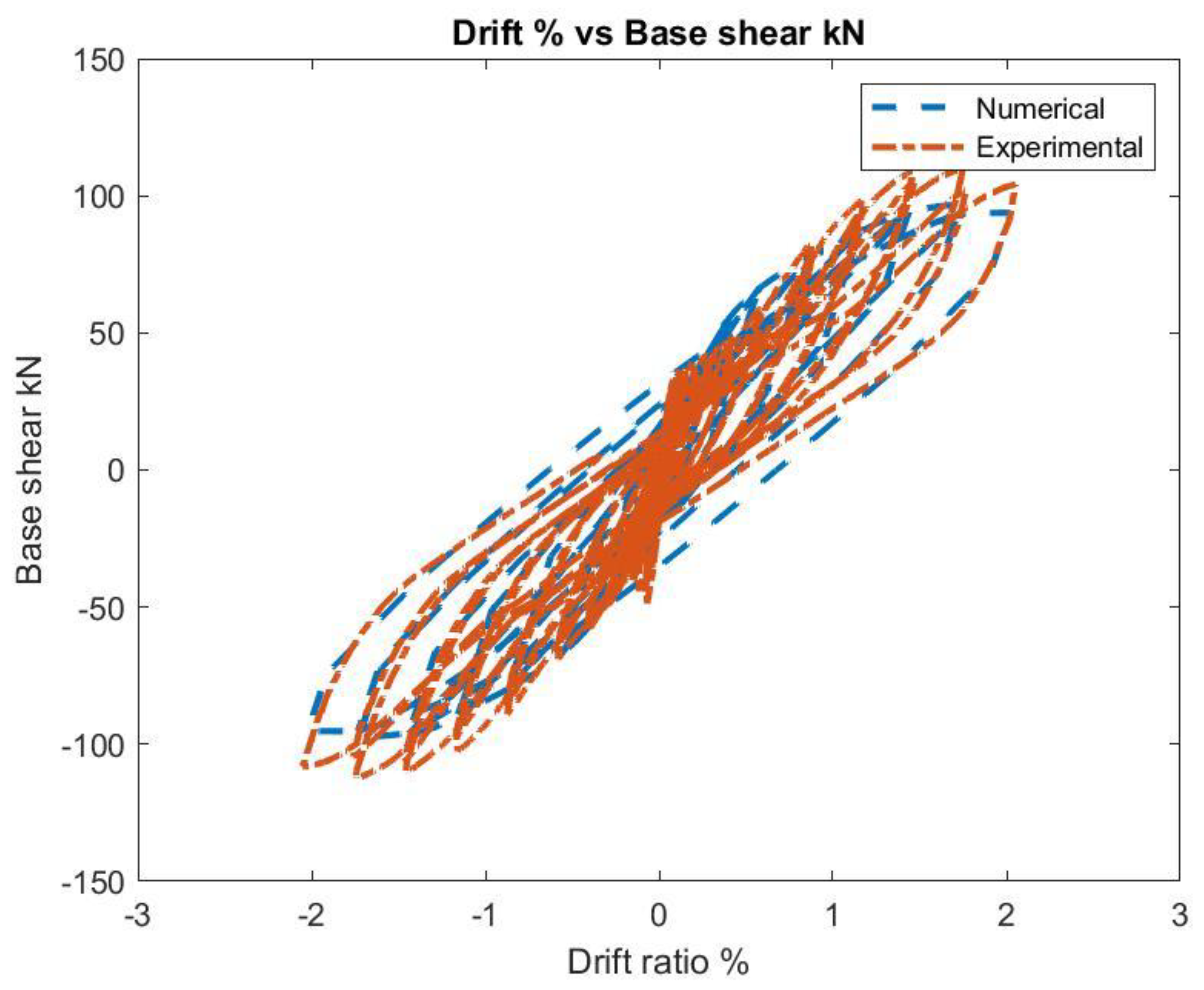
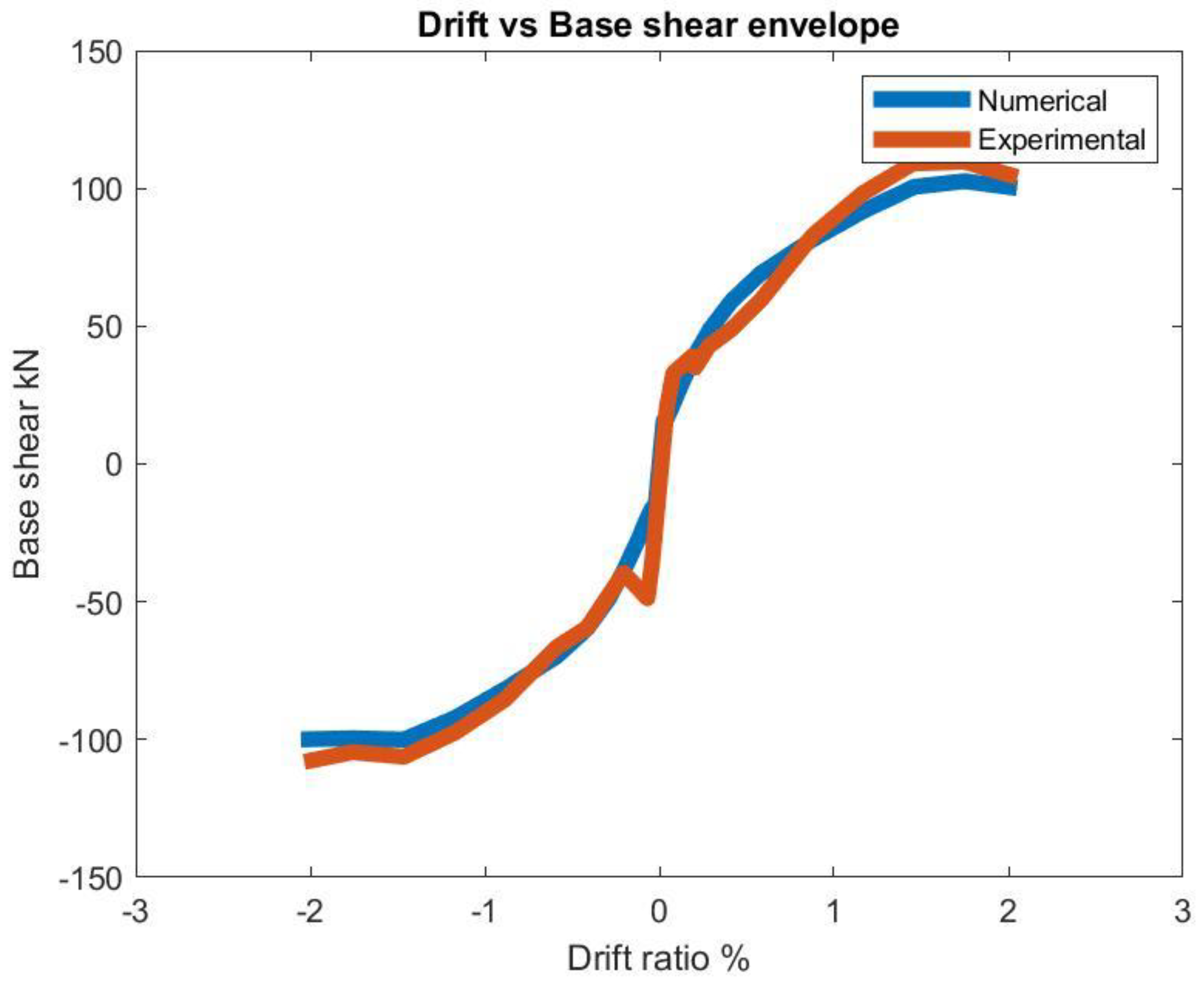
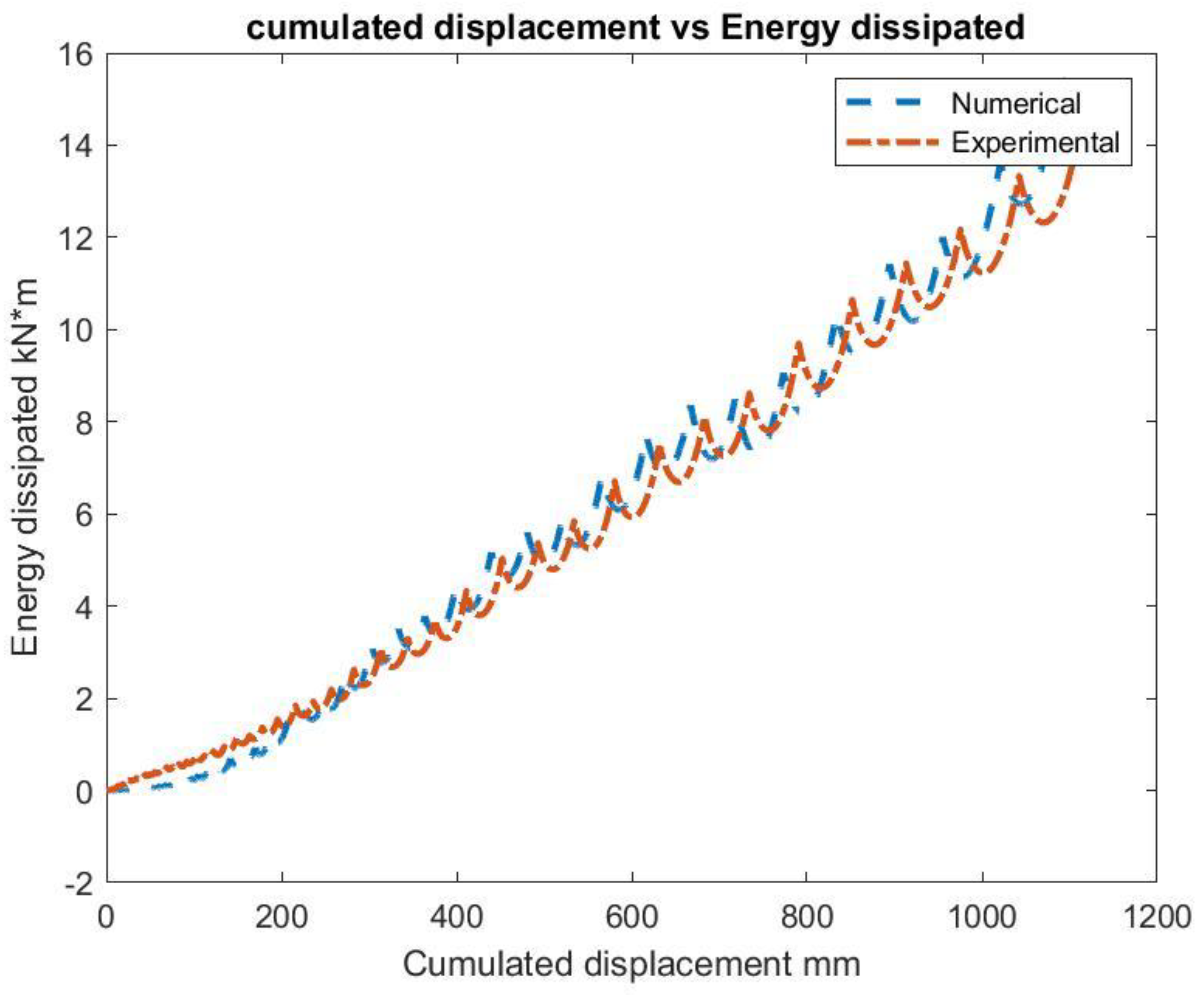
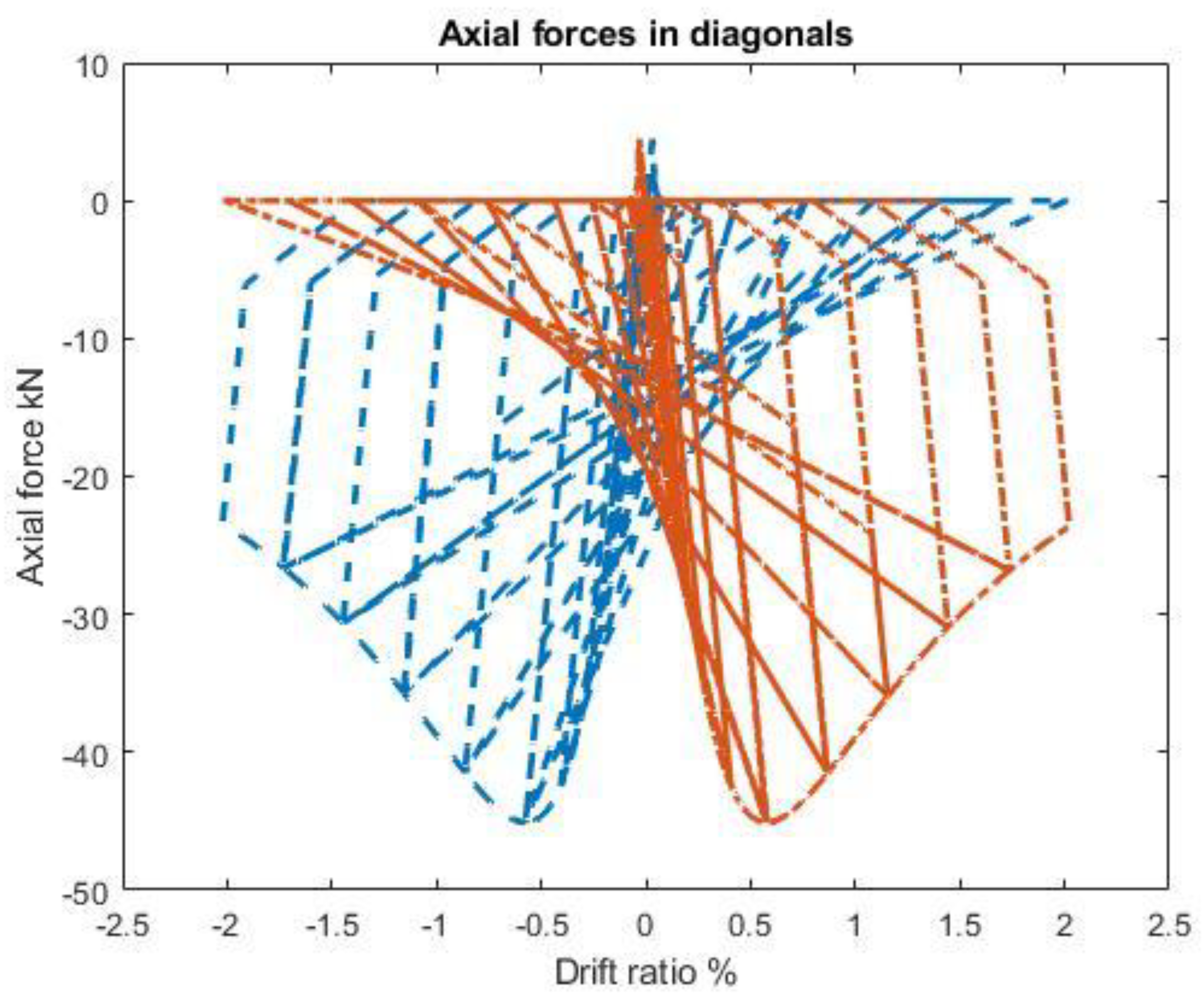
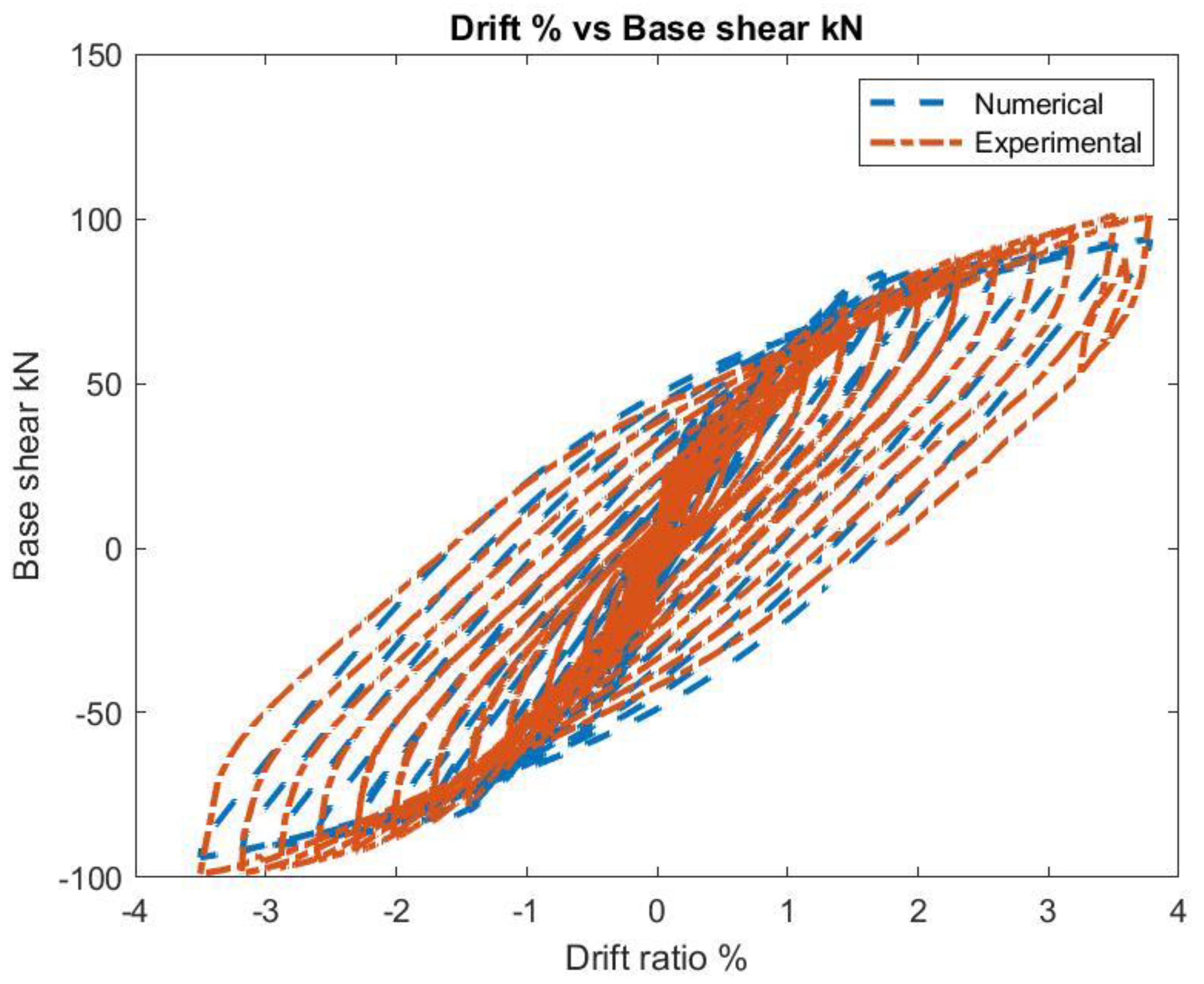
2. VALIDATION. Plots Comparison Between Experiments and Numerical.

In the following plots the numerical results are compared with experimental results:
Masonry infill wall
-
Drift vs Base Shear Figure 1
-
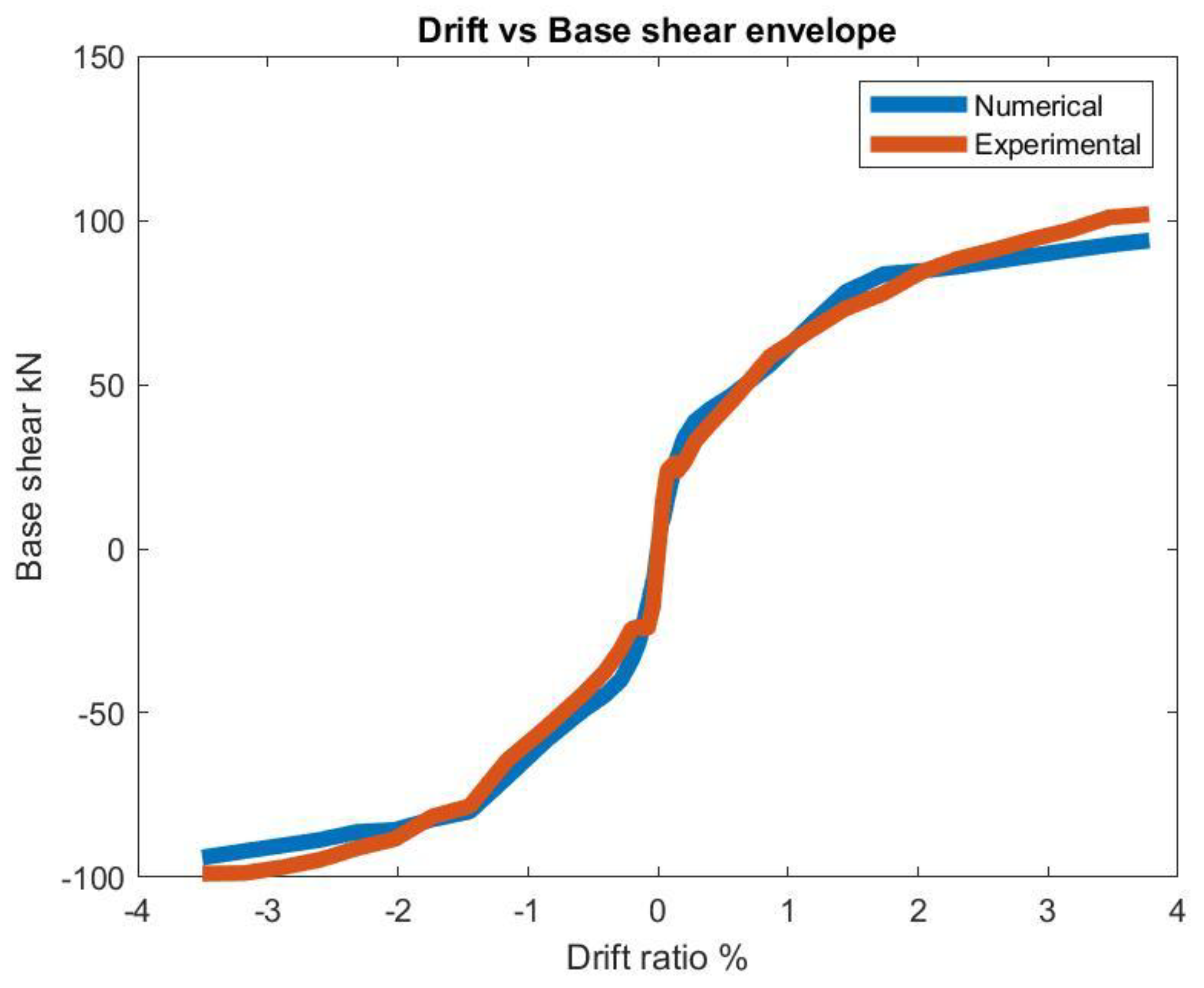
Drift vs base shear envelope Figure 2
-
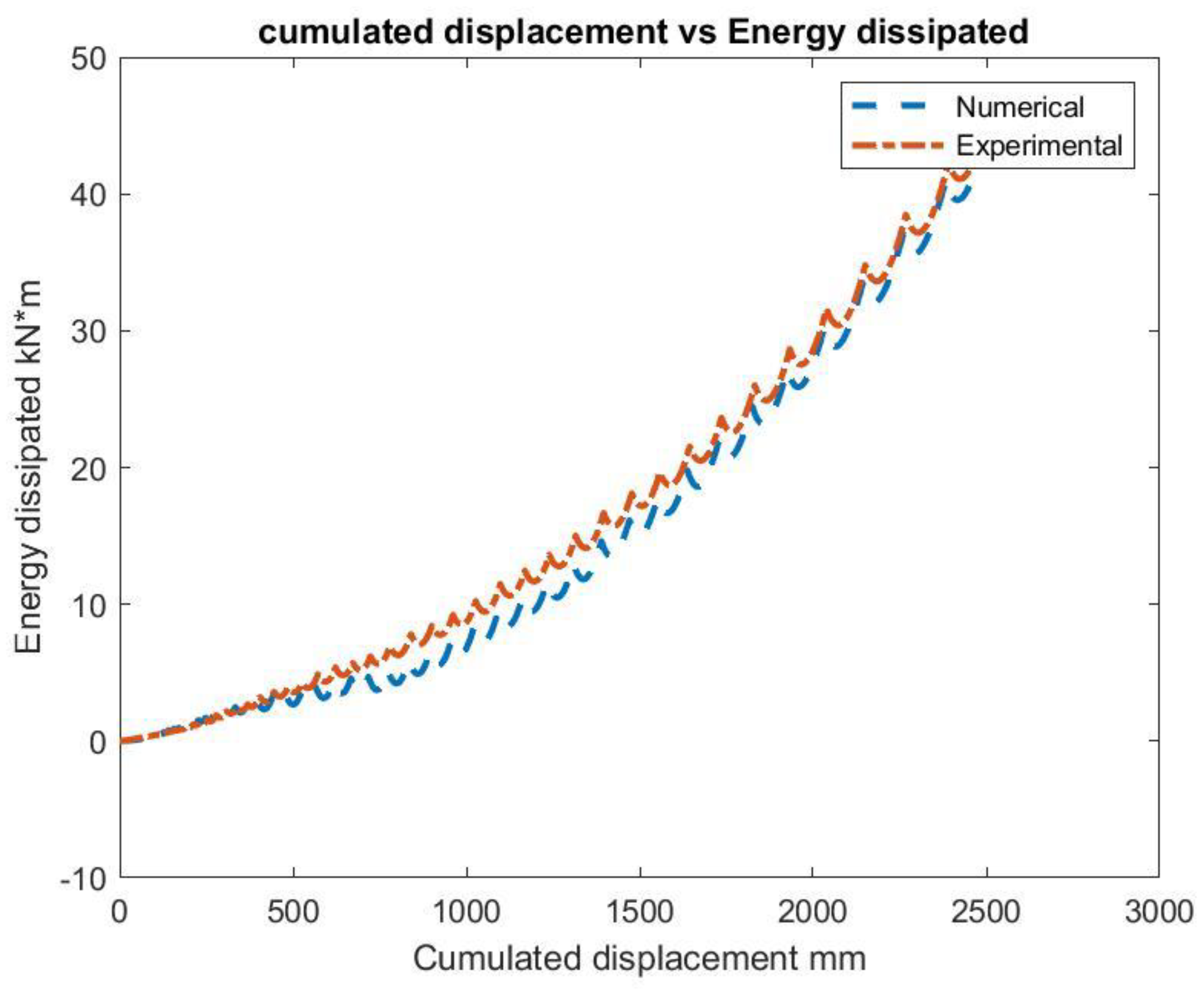
Cumulated displacement vs energy dissipated Figure 3
-
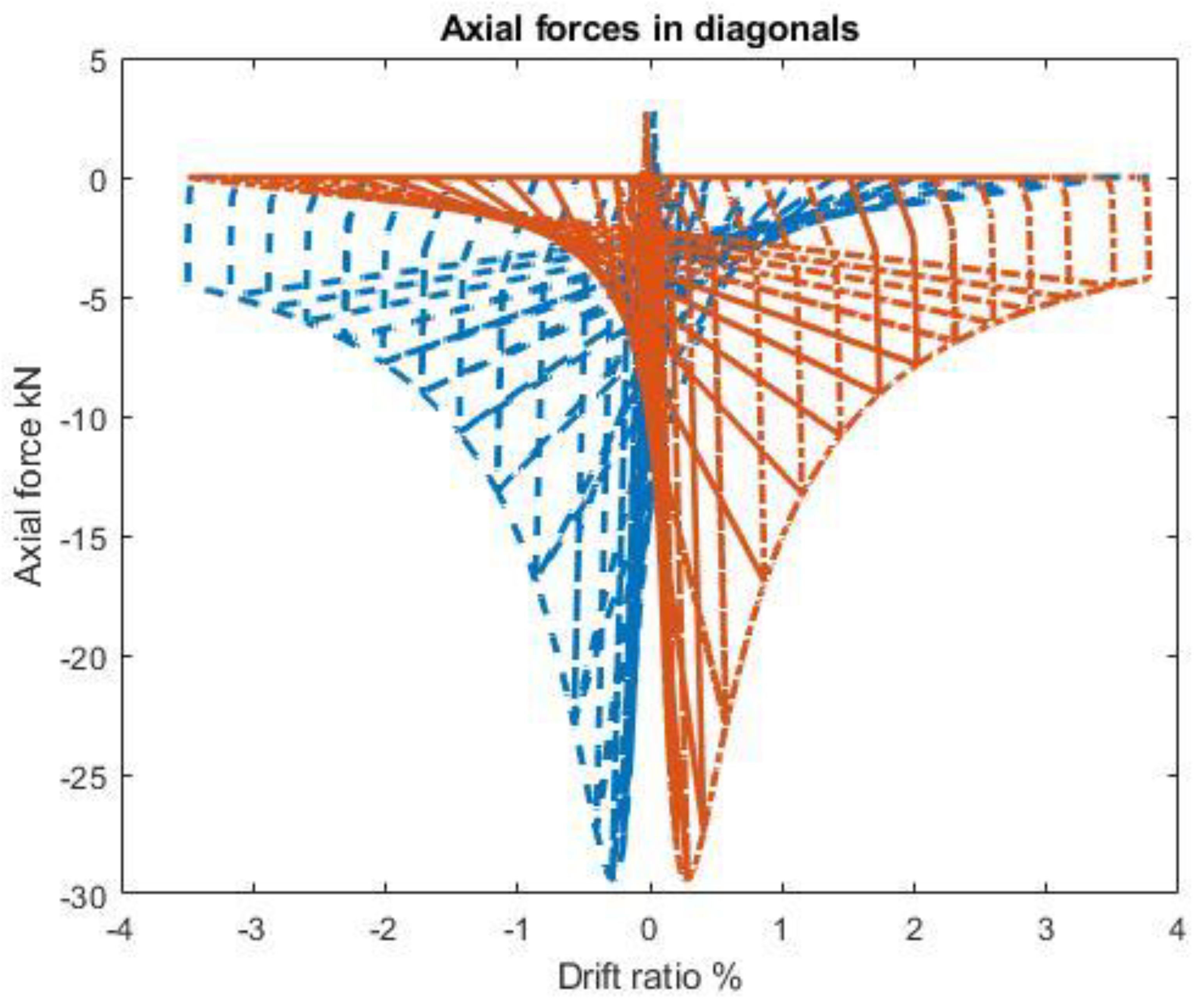
Equivalent diagonals axial forces Figure 4
Masonry infill wall with rubber bricks at the corners:
-
Drift vs Base Shear Figure 5
-
Drift vs base shear envelope Figure 6
-
Cumulated displacement vs energy dissipated Figure 7
-
Equivalent diagonals axial forces Figure 8
Masonry infill wall
Error Base shear : mean value=-9.77% ; standard deviation=4.58%
Masonry infill wall with rubber bricks at the corners:
Error Base shear: mean value=0.74% standard deviation=5.97% ;

3. Test Definition

The test definition is given by Pallares [3] in Figure 9 and Figure 10

4. Conclusions

The purpose of this article is to use a numerical model to match the experimental results in case of steel frames with infilled masonry with or without rubber bricks at the corners (SISBRICK) under cyclic loading. The analysis are performed with opensees software using for preprocessing and postprocessing matlab. In this model the beam and column made of steel are modelled with displacement based elements and using section fiber models at each fiber the Giuffre Menegotto Pinto is used, to model the infill masonry with or without SISBRICK the concrete model based on Thorenfeldt curve is used to model the diagonals with high strength under compression and low under tension.
Concluding it can be checked perfect agreement between numerical analysis and test results.
Further research has been done also on reinforced concrete frames with infilled masonry with or without rubber bricks at the corners Agüero [4,5].

Nomenclature

according to Eurocode.

References

  1. Agüero. https://es.mathworks.com/matlabcentral/fileexchange/124635-steel-frame-masonry-wall-dynamic.
  2. Agüero. https://es.mathworks.com/matlabcentral/fileexchange/124570-cyclic-analysis-of-steel-frames-with-masonry-infilled-wall?s_tid=prof_contriblnk.
  3. Francisco J. Pallarés, Luis Pallarés, Experimental study on the response of seismically isolated masonry infilled steel frames during the initial stages of a seismic movement, Engineering Structures, Volume 129, 2016, Pages 44-53. [CrossRef]
  4. Agüero. https://www.mathworks.com/matlabcentral/fileexchange/124570-cyclic-analysis-of-steel-frames-with-masonry-infilled-wall.
  5. Agüero. https://es.mathworks.com/matlabcentral/fileexchange/125030-concrete-frame-masonry-wall-dynamic-opensees?s_tid=prof_contriblnk.
Figure 1. Masonry Base shear vs Drif ratio.
Preprints 149203 g001
Figure 2. Masonry Base shear vs shear ratio envelope.
Preprints 149203 g002
Figure 3. Masonry Energy dissipated vs cumulated displacement.
Preprints 149203 g003
Figure 4. Masonry Axial foce vs drif ratio.
Preprints 149203 g004
Figure 5. SISBRICK Masonry Base shear vs Drif ratio.
Preprints 149203 g005
Figure 6. SISBRICK Base shear vs shear ratio envelope.
Preprints 149203 g006
Figure 7. SISBRICK Energy dissipated vs cumulated displacement.
Preprints 149203 g007
Figure 8. SISBRICK Axial foce vs drif ratio.
Preprints 149203 g008
Figure 9. Frame geometry.
Preprints 149203 g009
Figure 10. Frame Test.
Preprints 149203 g010
Disclaimer/Publisher’s Note: The statements, opinions and data contained in all publications are solely those of the individual author(s) and contributor(s) and not of MDPI and/or the editor(s). MDPI and/or the editor(s) disclaim responsibility for any injury to people or property resulting from any ideas, methods, instructions or products referred to in the content.
Copyright: This open access article is published under a Creative Commons CC BY 4.0 license, which permit the free download, distribution, and reuse, provided that the author and preprint are cited in any reuse.
Prerpints.org logo

Preprints.org is a free preprint server supported by MDPI in Basel, Switzerland.

Subscribe

Disclaimer

Terms of Use

Privacy Policy

Privacy Settings

© 2025 MDPI (Basel, Switzerland) unless otherwise stated