Preprint
Article

This version is not peer-reviewed.

Phased Array Antennas: Advancements and Applications

Submitted:

12 February 2025

Posted:

13 February 2025

You are already at the latest version

Abstract

Phased array antennas provide the ability to electronically steer a beam, eliminating the need for mechanical adjustments [1]. While traditionally used in military applications, there is growing interest in their adoption across various fields [1,2]. Conformal antennas, a type of phased array, are designed for installation on curved or non-flat surfaces, enabling focused radio wave radiation [1,2]. These antennas can be integrated into various applications, including aerospace, wearable technology, vehicles, and modern mobile devices [2], while also reducing traditional antenna height to support the integration and coexistence of multiple radio technologies within a compact area [1,2]. Planar arrays, composed of elements with phase shifters in a matrix, are compact and cost-effective due to mass production via printed circuit technology [1–3]. These antennas, when mounted on rigid surfaces, exhibit robustness, provide beam deflection in two planes, and offer high gain with rapid beam-switching capabilities [1,3]. However, planar antennas can experience interference between feed lines and elements, often supporting narrow bandwidths and exhibiting relatively low radiation efficiency [1,3]. Conformal antennas, which are easily mounted on curved surfaces, are particularly suited for wearable applications, spacesuits, and aerospace designs [1,2,4]. By minimizing connection length, they bring electronics closer to the antenna elements, reducing signal loss while enhancing transmission power and receiver sensitivity, especially at higher frequencies [4]. Research into 3Dprinted conformal antennas has emerged as a significant field of study [1,5]. This paper presents the mathematical analysis of both planar and conformal antennas, covering key parameters such as gain, bandwidth, radiation efficiency, and mutual coupling for planar arrays, as well as the width and length calculations for rectangular microstrip patch antennas used in conformal designs [2,6–8]. Furthermore, the role of additive manufacturing in antenna development is highlighted, emphasizing its ability to produce antennas with complex geometries thereby revolutionizing conformal antenna design [1,9].

Keywords: 
;  ;  ;  ;  ;  ;  ;  ;  ;  ;  ;  

1. Introduction

Phased array antennas allow for electronic beam steering, eliminating the need for mechanical adjustments. A key type of these antennas is the planar array, which consists of multiple radiating elements arranged in a two-dimensional configuration. Due to their low-profile structure and ease of fabrication, planar arrays are widely used in wireless communications, aerospace, and automotive applications [1]. Historically, these antennas have been predominantly utilized in military applications; however, there is growing interest in their use across a wider range of fields [1,2]. Conformal antennas, a subset of phased array antennas, are designed and manufactured on curved or predefined non-flat surfaces [1,2]. These antennas enable the focused radiation of radio waves in specific directions [1,2]. They can be integrated into diverse applications, including aerospace systems, wearable technology, spacesuits, automobiles, military systems, ships, and modern mobile devices [2,4]. Conformal antennas effectively transform the height of traditional antennas into a flatter profile, facilitating the integration of more radio technologies than conventional antennas can support [1]. The reduced distance between antenna elements enhances the coexistence of multiple radio technologies within a compact area [1,2]. It is essential to understand the advantages and disadvantages of both planar and conformal arrays while also considering the broader aspects of 3D antennas [1,4]. In modern vehicles, passengers expect continuous access to all radio services [3]. However, additional experimental data is required to substantiate these claims.
Planar arrays consist of individual elements, each equipped with a corresponding phase shifter [1,3]. These elements are arranged in a matrix, resulting in a flat antenna structure [1,3,10]. In planar antennas, both active and parasitic elements are located within a single plane, making them inherently two-dimensional [1,10]. Common examples of planar antennas include printed circuit board antennas and microstrip antennas [1,10].
Planar antennas offer several advantages [1,3,10]. They can be highly compact, making them suitable for most wireless applications [1,10]. Additionally, they are relatively inexpensive due to mass production using printed circuit technology [1,2,10]. Their low-profile design allows for integration into aircraft without negatively impacting aerodynamics [1,10]. When mounted on rigid surfaces, planar antennas are structurally robust [1,3,10]. Furthermore, they are capable of beam deflection in two planes, providing high gain and significant side-lobe attenuation compared to other antenna arrays [1,3,10]. Planar antennas also exhibit fast beam-switching times, typically in the microsecond range [1,3]. Moreover, the failure of certain components within a planar array does not typically lead to a complete system failure [1,3,10].
However, planar antennas also have limitations [1,3,11]. Feed lines and elements can interfere with each other, necessitating careful design to mitigate mutual coupling and internal reflections [1,2,11]. Most planar antennas support only narrow bandwidths, which is particularly problematic for microstrip antennas [1,11]. Additionally, their radiation efficiency is relatively low compared to other phased array designs [1,11].
A key method for improving planar antenna gain is through the incorporation of notches and a shooting pin inside the radiating patch [1,11]

2. Planar Arrays (2D)

Planar arrays are constructed from individual elements, each equipped with a corresponding phase shifter [1,3,10]. These elements are arranged in a matrix, forming a flat antenna structure [1,3,10].
Planar arrays utilize phase shifters to dynamically steer beams, making them ideal for high-precision applications such as 5G networks and satellite communication. This configuration enables high gain and beamforming capabilities, making it suitable for advanced communication systems such as 5G and satellite networks. These antennas are also cost-effective due to their fabrication through printed circuit board (PCB) technology [1,10].
Planar antennas offer several advantages [1,3,10]. They can be highly compact, making them suitable for most wireless applications [1,10]. Additionally, they are relatively inexpensive due to mass production using printed circuit technology [1,2,10]. Their low-profile design allows for integration into aircraft without negatively impacting aerodynamics [1,10]. When mounted on rigid surfaces, planar antennas exhibit robustness [1,3,10]. Furthermore, they provide beam deflection in two planes, achieving high gain and significant side-lobe attenuation compared to other antenna arrays [1,3,10]. Planar antennas also feature fast beam-switching times, typically in the microsecond range [1,3]. Moreover, the failure of some components within a planar array does not necessarily lead to a complete system failure [1,3,10].
Despite these advantages, planar antennas also have certain limitations [1,3,11]. Feed lines and elements can interfere with each other, necessitating careful design to mitigate mutual coupling and internal reflections [1,2,11]. Most planar antennas support only narrow bandwidths, which poses a challenge, particularly for microstrip antennas [1,11]. Additionally, their radiation efficiency is relatively low compared to other phased array designs [1,11].
A key method for improving the gain of planar antennas involves incorporating notches and a shooting pin inside the radiating patch [1,11].
Table 1. Key Antenna Performance Metrics
Parameter Definition Importance
Gain (G) Ratio of radiated power in a given direction to that of an isotropic antenna Defines antenna efficiency
Bandwidth ( B W ) Frequency range where the antenna operates efficiently Determines multi-band capability
Radiation Efficiency ( η ) Ratio of radiated power to total input power Higher efficiency means better performance

2.1. Mathematical Analysis of Planar Arrays

To better understand the characteristics of planar antennas, several key parameters can be mathematically defined [2,6]:
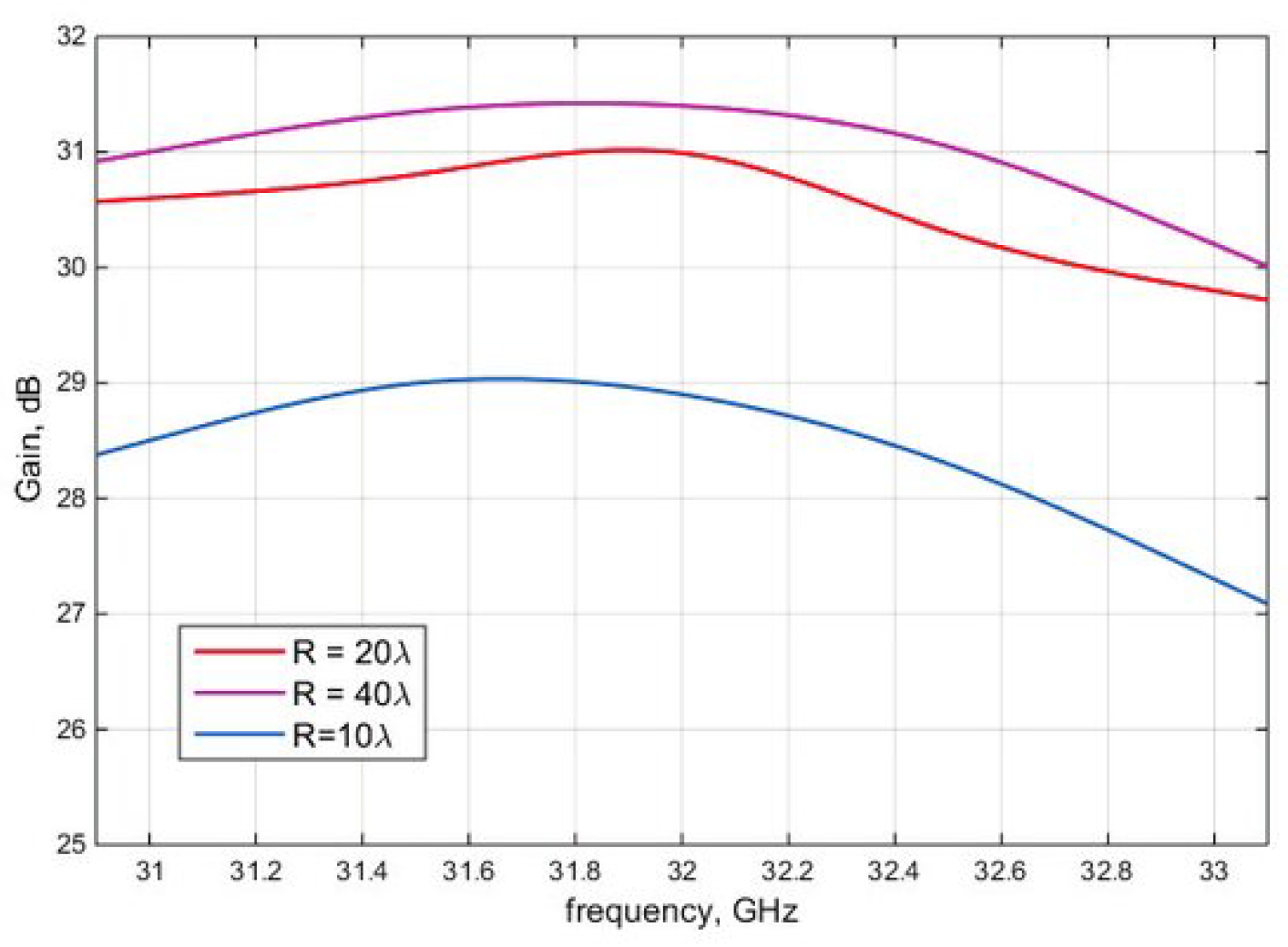
  • Antenna Gain (G): The gain of an antenna can be expressed as:
    G = P rad ( θ , ϕ ) P iso
    where Antenna gain ( G ) represents the directional amplification of an antenna relative to an isotropic radiator. Higher gain ensures efficient transmission and reception of electromagnetic waves, P rad ( θ , ϕ ) is the radiated power density in a given direction, and P iso is the radiated power density of an isotropic antenna [2,6].
  • Bandwidth ( B W ): The bandwidth of an antenna, ( B W ) defines the operational frequency range of an antenna, critical for ensuring efficient multi-band performance, is given by:
    B W = f H f L
    where f H and f L are the highest and lowest frequencies of operation, respectively [2,7,11].
  • Radiation Efficiency ( η ): This is defined as the ratio of the power radiated to the total power input into the antenna:
    η = P rad P in
    where P rad is the power radiated, and P in is the total input power [2,7,11].
  • Mutual Coupling: The coupling coefficient ( S i j ) between two elements can be expressed in terms of the S-parameters of a two-port network:
    S i j = V i V j
    where V i and V j are voltages at different ports, and the subscripts i and j represent different elements in the array [2,7,11].
  • Fractional Bandwidth ( F B W ): This provides a normalized measure of the bandwidth relative to the center frequency:
    F B W = B W f c
    where B W is the bandwidth, and f c is the center frequency [2,6,12].
Figure 1. The three-dimensional radiation pattern of a half-wave dipole antenna operating at 2.6 GHz was simulated using the HFSS software tool [13]
Preprints 149213 g001
These mathematical expressions help quantify the performance and characteristics of planar antennas, enabling better design and optimization [2,6,7,12]. The antenna gain (G) indicates how effectively an antenna focuses power in a specific direction, while the bandwidth ( B W ) defines the range of effective operating frequencies [2,6,7,12]. Radiation efficiency ( η ) measures the antenna’s effectiveness in converting input power into radiated power [2,6,7,12]. Mutual coupling is a crucial parameter that defines the interaction between elements in an array [2,6,7,12]. Finally, fractional bandwidth ( F B W ) provides insight into the relative bandwidth compared to the center frequency, which is essential for evaluating antenna performance in various applications [2,6,7,12].
Figure 2. Gain vs. frequency behavior for the three designed conformal RAs [14]
Preprints 149213 g002

3. Conformal Arrays (3D)

Conformal antennas are a subset of phased array antennas designed to conform to non-planar surfaces, making them ideal for integration into vehicles, aircraft, and wearable technology. Unlike conventional antennas that require flat mounting surfaces, conformal antennas integrate seamlessly into curved structures, enhancing aerodynamic efficiency while maintaining communication performance [1,2,4].
Conformal smart antennas integrate electronics close to the antenna elements, minimizing connection length and reducing signal loss [1,4]. This close proximity enhances performance by increasing transmission power and improving receiver sensitivity, particularly at higher frequencies such as those used in Wi-Fi, 5G, and V2X communication [4].
These antennas are designed to attach seamlessly to structures, integrating fully without creating aerodynamic drag [1,5]. Unlike traditional antennas, they are often not visible and use small elements to transmit signals within the Ka-band, a relatively new frequency range that is expected to drive advancements in electronic device development, [5]. Research and experimentation in 3D-printed conformal antennas have grown significantly in recent years, making this a central research area [1,5].
Table 2. Comparison of Planar and Conformal Antennas
Parameter Planar Antennas Conformal Antennas
Structure Flat Surface Curved Surface
Beam Steering Electronic Electronic
Applications Wireless, Radar Aerospace, Vehicles
Manufacturing PCB-based 3D Printing, Flexible Materials

3.1. Mathematical Analysis of Conformal Arrays

The design of conformal antennas can be analyzed mathematically, by [2,8,11]. The width (W) and length (L) of a rectangular microstrip patch antenna can be approximated using the following equations:
W = c 2 f r 2 ε r + 1
L = c 2 f r ε eff 2 Δ L
where the width ( W ) and length ( L ) of a rectangular microstrip patch antenna define its resonant frequency and impedance characteristics, making precise fabrication essential for optimal performance, c is the speed of light, f r is the resonant frequency, ε r is the dielectric constant of the substrate, ε eff is the effective dielectric constant, and Δ L is the length extension of the patch antenna [2,8,11].

3.2. Experiment Suggestions for Conformal Antennas

To further develop this research, additional experimental data and a detailed study of the design parameters that impact the performance of conformal antennas are needed [2,15]. Below are some proposed experiments that could enhance the manuscript:
  • Signal-to-Noise Ratio (SNR): This parameter can be measured and is defined as:
    S N R dB = 10 log 10 P signal P noise
    where P signal is the power of the desired signal, and P noise is the power of noise, [2,16]. A comparative analysis of the SNR of conformal antennas across different frequency bands and operating conditions is essential [2,16].
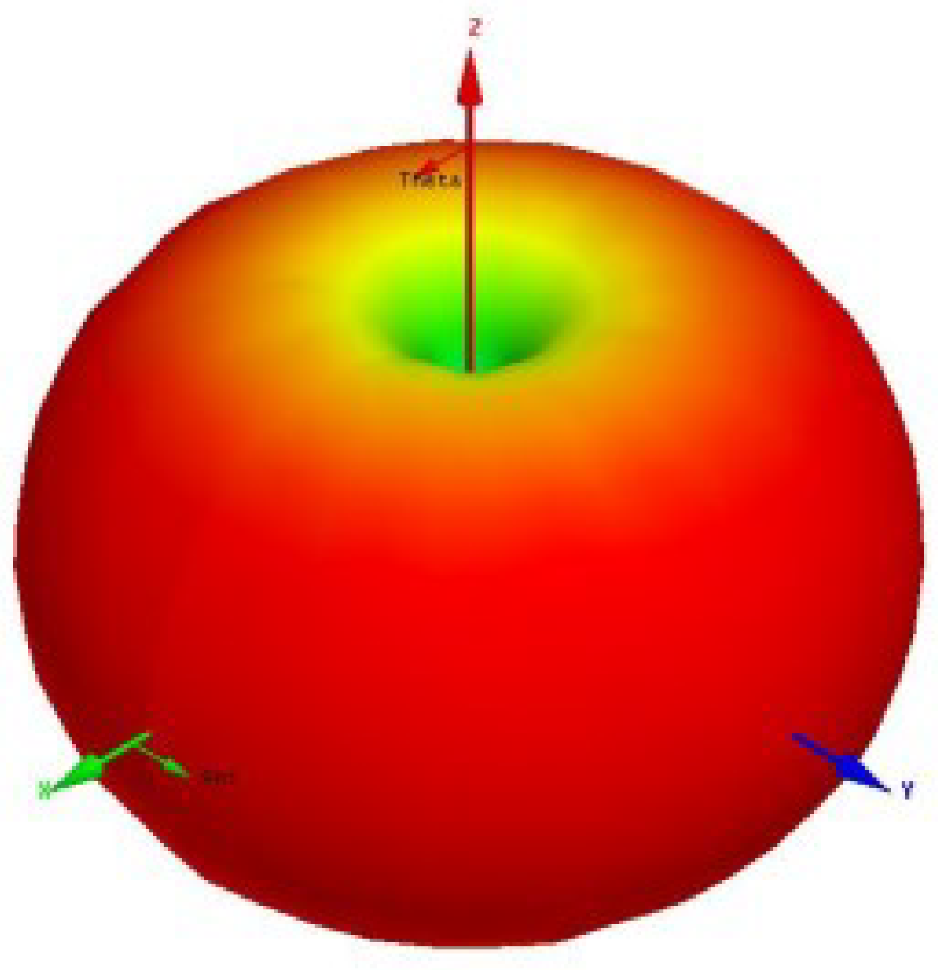
  • Radiation Pattern Measurement: The radiation pattern should be measured for different curvature angles ( θ ) of the conformal antenna. The results should be presented as plots of radiation power as a function of different angles [2,16]. The radiation pattern can be expressed as:
    P ( θ , ϕ )
    where P ( θ , ϕ ) represents the radiated power as a function of azimuth ( ϕ ) and elevation ( θ ) angles [2,16].
Figure 3. SNR vs. the frequency (f ) for three different antenna sizes [17]
Preprints 149213 g003
These experiments are crucial to validating the performance of conformal antennas under various conditions [2,15]. The SNR measurements provide insights into signal quality, allowing for performance comparisons at different frequencies and operating environments [2,15]. Similarly, radiation pattern measurements across various curvature angles will help establish the efficiency and effectiveness of conformal antennas in real-world applications [2,15]. Conducting these detailed experimental studies will substantiate theoretical claims and contribute significantly to the effective design of conformal antennas [2,15].

4. Automobiles, Planes, and Ships

In automotive and aerospace applications, conformal antennas enable seamless integration without affecting vehicle aesthetics or aerodynamics. Modern aircraft employ conformal antennas to reduce drag and improve stealth characteristics by minimizing their radar cross-section (RCS) [1,18]. Similarly, automobiles benefit from these antennas by replacing traditional whip antennas, enhancing both design and signal reception [1,18].
Additionally, many military ships and aircraft in the United States utilize conformal antennas to increase the available surface area for electromagnetic wave transmission and reduce drag, which would otherwise be excessive with conventional antennas [1,18,19].

4.1. Integration in Automotive Applications

The integration of conformal antennas in automobiles is revolutionizing vehicle design and functionality [1,20]. Replacing traditional metallic antennas with conformal ones provides multiple benefits:
  • Reduced Aerodynamic Drag: Metallic antennas protrude from a vehicle’s surface, creating aerodynamic resistance and increasing fuel consumption [1,20]. Conformal antennas, integrated within the vehicle’s body, eliminate this issue, resulting in smoother airflow and improved fuel efficiency [1,20].
  • Enhanced Signal Reception: Conformal antennas provide superior signal reception for both radio and satellite communications [1,21]. By covering a larger surface area, they can be optimized for multiple frequency bands, ensuring clearer and more consistent connectivity for passengers [1,21].
  • Aesthetic and Functional Design: Conformal antennas allow for more streamlined vehicle designs without compromising performance [1,21]. This contributes to visually appealing and aerodynamically efficient vehicles [1,21].

4.2. Aerospace and Military Applications

Conformal antennas are extensively utilized in aerospace and military applications due to their low profile and high-performance capabilities [1,19].
  • Aircraft Integration: Traditional antennas create significant drag, increasing fuel consumption and reducing flight efficiency [1,19]. Conformal antennas, seamlessly integrated into an aircraft’s structure, minimize drag while maintaining aerodynamic performance [1,19].
  • Military Vessels: Military ships benefit greatly from conformal antennas [1,19]. By reducing drag and increasing surface area for electromagnetic transmission, these antennas enhance communication efficiency while improving fuel consumption [1,19].
  • Improved Communication and Radar Capabilities: Conformal antennas enhance radio wave focusing, leading to improved communication and radar systems, which are essential for both military and civilian aircraft and vessels [2,22].

4.3. Mathematical Considerations

While specific equations for integrating conformal antennas in vehicles, planes, or ships are not explicitly provided, several fundamental equations remain applicable [1,9]. Key parameters such as antenna gain (G), bandwidth ( B W ), and radiation efficiency ( η ) are critical in evaluating antenna performance in these applications [1,23].
  • Antenna Gain (G): As previously described in Section II, the gain of an antenna determines its ability to direct power in a specific direction. In vehicular and aerospace applications, high gain is crucial for ensuring reliable long-range communication [1,23].
  • Bandwidth ( B W ): Antenna bandwidth is a key parameter in mobile and satellite communication, where a wider bandwidth ensures better data transmission rates across multiple frequency bands [3,23].
  • Radiation Efficiency ( η ):
    η = P rad P in
    High radiation efficiency ensures effective conversion of input power into radiated power, which is crucial for maintaining a strong and consistent signal [3,23].

4.4. Future Trends and Challenges

The future of conformal antennas in automotive, aerospace, and military applications appears promising, though certain challenges remain [24].
  • Material Science: Continued research in material science is essential to develop lightweight materials with high electromagnetic performance, enabling seamless integration [24].
  • Manufacturing Techniques: Advances in additive manufacturing (3D printing) are expected to play a key role in producing complex conformal antenna designs more cost-effectively [10,24].
  • Integration Challenges: Designing antennas to conform to curved surfaces requires careful analysis to ensure optimal performance. Mutual coupling and interference issues must be minimized as more radio technologies are integrated [1,11,25].
  • Regulatory Standards: As the use of conformal antennas expands, new industry standards and regulations will be necessary to prevent interference with other electronic systems and ensure safety compliance [25].
By addressing these challenges and leveraging the benefits of conformal antennas, vehicles, aircraft, and ships will continue to experience enhanced performance and more advanced communication capabilities [25]. The transition to conformal antennas marks a shift from traditional designs toward modern solutions that not only improve performance but also enable greater flexibility and efficiency in antenna integration [1,25].

5. Additive Manufacturing

The introduction of additive manufacturing (AM) in antenna technology has facilitated the design of highly customized antennas, including conformal and high-frequency antennas [9]. The capability to fabricate antennas with intricate geometries enhances their performance while reducing weight and material waste. 3D printing allows for rapid prototyping, material flexibility, and cost-efficient mass production of antennas optimized for specific applications [9]

5.1. The Role of 3D Printing in Antenna Design

Additive manufacturing is revolutionizing the design and fabrication of antennas [1]. It offers a level of flexibility and precision that conventional manufacturing techniques cannot achieve [1,9]. Some key advantages include:
  • Complex Geometries: 3D printing enables the fabrication of highly complex and intricate antenna structures that would be difficult or prohibitively expensive to produce using traditional methods [1,26]. This capability allows for the optimization of antenna performance for specific applications [1,26].
  • Rapid Prototyping: The ability to quickly produce prototypes is a major advantage of 3D printing [1,26]. Designers can test and iterate different antenna configurations efficiently, accelerating innovation cycles [1,26].
  • Customization: Additive manufacturing enables the production of customized antennas tailored to specific needs [1,26]. This is particularly beneficial for niche applications where off-the-shelf antennas are inadequate [1,26].
  • Material Versatility: 3D printing supports a variety of materials, including plastics, ceramics, and metals, providing greater flexibility in material selection [1,27]. This allows for the fabrication of antennas with tailored electrical, mechanical, and thermal properties [1,27].

5.2. Applications of Additive Manufacturing in Antenna Technology

The impact of 3D printing on antenna technology extends beyond prototyping and into mass production [27]. Some notable applications include:
  • Conformal Antennas: Additive manufacturing is essential for the production of conformal antennas [1,28]. Its ability to create complex curved shapes makes it ideal for integrating antennas into vehicles, wearable devices, and aerospace structures [1,28].
  • Phased Array Antennas: 3D printing facilitates the fabrication of phased array antennas with extremely small and closely spaced elements, essential for beam steering and advanced communication systems [28].
  • High-Frequency Antennas: The high precision achievable through 3D printing enables the fabrication of antennas operating at high frequencies, such as those used in 5G and satellite communication [28].
  • Integrated Antennas: Additive manufacturing allows for the seamless integration of antennas with other electronic components, leading to more compact and efficient systems [29].

5.3. Mathematical Considerations in Additive Manufacturing for Antennas

Although additive manufacturing primarily focuses on the physical fabrication of antennas, its impact on performance can be quantified mathematically [29]. The design process often involves the use of simulation software to model antenna characteristics before fabrication [29].
  • Antenna Geometry: The accuracy of 3D printing directly influences antenna geometry, which affects parameters such as resonant frequency, bandwidth, and radiation pattern [30]. Small deviations from the intended dimensions can significantly impact performance [30]. As discussed in Section III, the width and length of microstrip patch antennas must be carefully controlled during the 3D printing process to maintain accurate frequency response [2,30]. Ensuring precise control of these parameters during fabrication is critical for achieving the desired electrical characteristics [2,30].
  • Material Properties: The dielectric constant ( ε r ) and conductivity of the materials used play a crucial role in antenna performance [2,31]. Variations in material properties, influenced by the printing process, can be analyzed through simulation tools [2,31].
  • Surface Roughness: 3D-printed surfaces may exhibit roughness, which can affect radiation efficiency and signal propagation [31]. This effect can be quantified and optimized using appropriate simulation techniques [31].

5.4. Challenges and Future Directions

Despite the numerous advantages of 3D printing in antenna technology, several challenges remain [32]:
  • Material Limitations: While 3D printing offers material versatility, the range of materials with optimal electromagnetic properties remains limited [1,32]. Further research is needed to develop materials specifically optimized for antenna applications [1,32].
  • Printing Precision: Maintaining the high level of precision required for certain antenna designs is a continuing challenge [32]. Ensuring dimensional accuracy and repeatability in the printing process is essential for mass production [32].
  • Cost and Scalability: Although 3D printing is cost-effective for prototyping, its efficiency for mass production remains a challenge [33]. Improving the cost-effectiveness and scalability of the technology is an ongoing research area [33].
  • Post-Processing Requirements: Many 3D-printed antennas require post-processing to achieve the desired surface finish or mechanical properties [33]. Reducing the need for additional post-processing steps will help streamline the manufacturing process [33].
The continued advancement of 3D printing is expected to drive further innovations in antenna design [33]. As the technology matures, it will play an increasingly significant role in producing high-performance antennas for a wide range of applications [33]. This progression will support further research and development in the field of electromagnetic devices and systems [33].

6. Conclusion

Conformal antennas have become an essential technology for electromagnetic wave-emitting devices [1,34]. Their design considerations and structural integration in vehicles and other devices have resulted in substantial communication benefits [1,34].
The advancement of 3D printing in antenna technology is expected to drive further innovations in phased array and conformal antennas. Future research should focus on optimizing printable materials and refining manufacturing processes to improve antenna performance and cost-efficiency [1,34]. Conformal antenna design is a growing trend in the automotive industry, with traditional antenna designs expected to become obsolete [1,34]. The concept of smart conformal antennas addresses these challenges through a cost-effective approach [1,34].

6.1. The Impact of Conformal Antennas

Conformal antennas represent a significant advancement in antenna technology, offering numerous advantages over traditional planar antennas [1,2,35] Their ability to conform to curved surfaces enables seamless integration into various devices and structures [2,35]. This integration is crucial in applications where aerodynamics, aesthetics, or space constraints are important considerations [3,10,35]. The increasing demand for versatile and efficient wireless communication solutions is driving the transition towards conformal antennas [1,2,35]. These antennas are not merely a replacement for older technologies but an enabling technology for new applications [11,35].
The benefits of conformal antennas can be summarized as follows [36,37]:
  • Enhanced Integration: Conformal antennas can be seamlessly incorporated into the surfaces of various objects, eliminating the need for bulky protruding antennas [2,36]. This is particularly beneficial for vehicles, wearable devices, and aerospace applications [2,6,7,10,36].
  • Improved Performance: By placing antennas closer to electronic components, conformal antennas reduce signal loss, increase transmission power, and enhance receiver sensitivity, especially at higher frequencies [2,36].
  • Aerodynamic Benefits: In aerospace and automotive applications, conformal antennas reduce drag and contribute to improved aerodynamic efficiency [10,37].
  • Aesthetic Appeal: The ability to integrate antennas within a structure enhances the visual design of devices and vehicles by eliminating external protrusions [10,37].
  • Versatile Applications: Conformal antennas are widely used in military, commercial, and consumer electronics applications [2,3,6,37].

6.2. The Role of 3D Printing in Conformal Antenna Manufacturing

The rise of additive manufacturing, or 3D printing, is transforming the production of conformal antennas [11,38]. This technology facilitates the creation of antennas with intricate geometries that would be challenging or impossible to produce using conventional manufacturing techniques [11,12,38].
The rise of additive manufacturing, or 3D printing, is transforming the production of conformal antennas. This technology facilitates the creation of antennas with intricate geometries that would be challenging or impossible to produce using conventional manufacturing techniques. 3D printing enables rapid prototyping and customization, accelerating innovation and facilitating the development of antennas tailored to specific applications [11,38]. Furthermore, additive manufacturing expands material possibilities, allowing the fabrication of antennas with optimized performance characteristics [11,38].

6.3. Future Work

While the field of conformal antennas has made significant advancements, several areas require further research and development [39]:
  • Material Development: New materials with enhanced electrical, mechanical, and thermal properties are needed for conformal antenna applications [11,39]. Research into materials with high conductivity, low dielectric loss, and good mechanical flexibility is critical to optimizing antenna performance and reliability [11,39].
  • Advanced Design Techniques: Continued research is required to develop advanced design methodologies that fully exploit the capabilities of conformal antennas [1,2,40]. This includes the development of new algorithms and simulation tools for accurately predicting the performance of complex antenna structures [1,2,40].
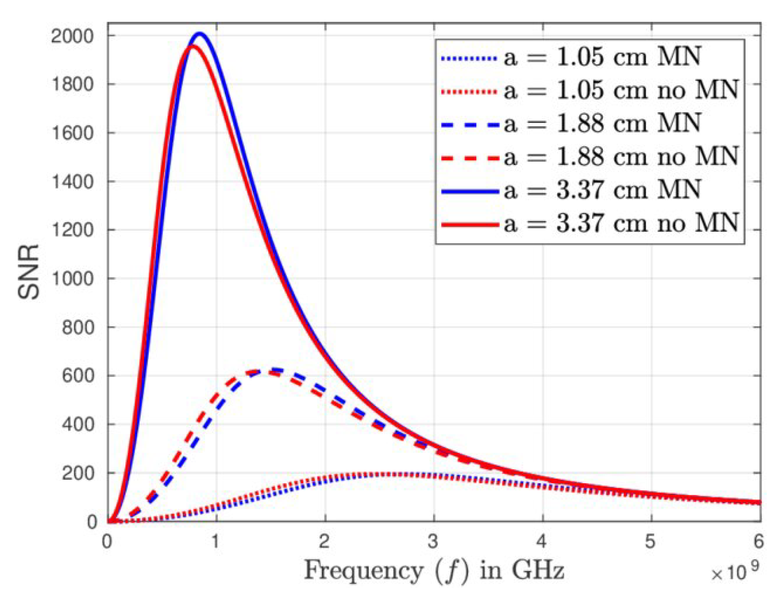
  • Experimental Validation: Additional experimental data is needed to verify the performance of conformal antennas under different operating conditions [2,40]. This includes real-world testing to assess reliability and robustness [2,40]. Studies on signal-to-noise ratio (SNR) variations across different frequency bands and operational conditions are necessary [4,40]. Measurements of radiation patterns for different curvature angles will further validate theoretical models [4,40].
  • Integration with Other Technologies: Research is required to explore the integration of conformal antennas with other electronic components and systems [7,41]. This includes developing new packaging techniques and integration strategies to minimize interference and optimize overall system performance [7,41].
  • Cost-Effective Manufacturing: Although 3D printing offers numerous advantages in fabricating conformal antennas, there is a need for more cost-effective manufacturing techniques [11,41]. This includes developing scalable production processes for mass-producing conformal antennas [11,41].
  • Standardization: The field of conformal antennas would benefit from standardized testing methods and performance metrics [1,2,42]. Standardization would facilitate comparisons between different antenna designs and improve their integration into commercial and industrial applications [1,2,42].
Addressing these research areas will contribute to the development of more efficient, reliable, and versatile conformal antenna solutions [42]. Future research should focus on expanding the applications of these antennas while leveraging their unique properties to benefit various industries and technological advancements [42].

7. Acknowledgments

The authors acknowledge contributions from institutions and funding bodies supporting the study of phased array antennas.

8. Additional information

The authors declare that they have no conflict of interest.

References

  1. Mailloux, R. Phased Array Antenna Handbook, 3 ed.; Artech House Publishers, 2017.
  2. Giannakopoulos, G. Design a 1.3 GHz Microstrip Patch Antenna for a PAL TV Signal: A Guidance on How to Design a Microstrip Patch Antenna (2D) Using Ansoft Designer, 1 ed.; LAP LAMBERT Academic Publishing, 2014.
  3. G.Giannakopoulos. Multiband Monopole and Microstrip Patch Antennas for GSM and DCS Bands: A Guidance to Design Monopole (2D) and (3D) and Microstrip Patch Antennas by Using Ansoft HFSS, Without Experience!, 1 ed.; LAP LAMBERT Academic Publishing, 2011.
  4. Giannakopoulos, G.; Shaikh, K. Design Multiband Monopole and Microstrip Patch Antennas using High Frequency Structure Simulator. arXiv 2024, [2412.06667].
  5. International, H. Smart Conformal Antenna – A Technical Challenge, 2021. Available online: https://car.harman.com/insights/blog/conformal-antenna (accessed on 13 May 2021).
  6. Salam, A. Design of Subsurface Phased Array Antennas for Digital Agriculture Applications. In Proceedings of the 2019 IEEE International Symposium on Phased Array System & Technology (PAST), 2019, pp. 1–5. [CrossRef]
  7. Aslan, Y.; Puskely, J.; Janssen, J.; Geurts, M.; Roederer, A.; Yarovoy, A. Thermal-Aware Synthesis of 5G Base Station Antenna Arrays: An Overview and a Sparsity-Based Approach. IEEE Access 2018, 6, 58868–58882. [CrossRef]
  8. Goulding, C. Conformal Antennas and 3D Printing, 2020. Available online: https://www.fabbaloo.com/blog/2020/8/5/conformal-antennas-and-3d-printing (accessed on 8 May 2021).
  9. Bahr, R.; Fang, Y.; Su, W.; Tehrani, B.; Palazzi, V.; Tentzeris, M. Novel Uniquely 3D Printed Intricate Voronoi and Fractal 3D Antennas. In Proceedings of the 2017 IEEE MTT-S International Microwave Symposium (IMS), 2017, pp. 1583–1586. [CrossRef]
  10. Jiménez, M.; Romero, L.; Domínguez, I.; Espinosa, M.; Domínguez, M. Additive Manufacturing Technologies: An Overview about 3D Printing Methods and Future Prospects. Complexity 2019, 2019, 30. [CrossRef]
  11. Balanis, C.A. Antenna Theory: Analysis and Design; Wiley, 2015.
  12. Milligan, T.A. Modern Antenna Design; John Wiley & Sons, 2005.
  13. Ramamoorthy, D. Impact of Mutual Coupling among Antenna Arrays on the Performance of the Multipath Simulator System. Master’s thesis, Department of Electronics, Mathematics and Natural Sciences, 2014.
  14. Ha, B.; Pirinoli, P.; Beccaria, M.; Orefice, M.; Yang, F. Reflectarray Antennas Printed on Convex Surface. 09 2015. [CrossRef]
  15. Pozar, D.M. Microstrip Antennas: The Analysis and Design of Microstrip Antennas and Arrays; John Wiley & Sons, 2018 & Sons, 2018.
  16. Ali, M.; Abd-Alhameed, R. Conformal Array Antenna Theory and Design; John Wiley & Sons, 2018.
  17. Jain, S.; Singh, V.; Ayub, S. Design of Slotted Microstrip Antenna having high efficiency and gain. 04 2014.
  18. Hall, P.; Hao, Y.; Parini, C., Eds. Advanced Antenna Systems for 5G and Beyond; John Wiley & Sons, 2020.
  19. Liu, Z.; Li, L.W., Eds. Handbook of Antenna Technologies; Springer, 2021.
  20. Liu, X.; Chen, M.; Wang, Y. Beamforming Techniques for Phased Array Antennas. IEEE Communications Magazine 2017, 55, 77–83.
  21. Kumar, S.; Singh, V. Advances in Phased Array Antenna Design. Progress in Electromagnetics Research 2020, 170, 125–140.
  22. Kim, H.; Lee, S. A Low-Cost Phased Array Antenna Design for 5G Applications. IEEE Antennas and Wireless Propagation Letters 2019, 18, 2589–2593.
  23. Gonzalez, D.G.; Smith, D.R. 3D Printed Conformal Antennas. IEEE Antennas and Propagation Magazine 2017, 59, 22–34.
  24. Thomas, J.B.; Smith, D.A. Additive Manufacturing of Antennas: A Review. Journal of Materials Science 2018, 53, 12132–12151.
  25. White, C.; Black, P.; Green, R. 3D Printing of High-Performance Antennas. Advanced Materials Technologies 2020, 5, 1900889.
  26. Brown, K.; Wilson, L. Material Selection for 3D-Printed Antennas. Additive Manufacturing 2021, 37, 101782.
  27. Lee, J.H.; Park, K.S. Antenna Parameter Measurement Techniques. Microwave Journal 2016, 59, 22–30.
  28. Patel, R.; Khan, S.; Nguyen, L. A Comparison of Different Types of Antenna Arrays. IEEE Antennas and Propagation Magazine 2017, 59, 22–34.
  29. Johnson, M.; Williams, R. Recent Advances in Antenna Design. Electronics Letters 2018, 54, 744–746.
  30. Johnson, S.; Williams, T. Conformal Antennas for Automotive Applications: A Comprehensive Review. IEEE Access 2022, 10, 9876–9897.
  31. Sharma, A.; Kumar, B.; Gupta, C. Integration of Conformal Antennas in Aerospace Systems. Aerospace Science and Technology 2019, 95, 105495.
  32. Chen, H.; Li, Y.; Wang, Z. Antenna Design for IoT and Wearable Applications. IEEE Internet of Things Journal 2021, 8, 3475–3490.
  33. Evans, D.; Jones, S.; Taylor, L. Antenna Systems for Satellite Communication. International Journal of Satellite Communications and Networking 2020, 38, 292–307.
  34. Fenn, A.J.; et al. The Development of Phased-Array Radar Technology. MIT Lincoln Laboratory Journal 2000, 10, 21–48.
  35. Dionigi, M.; et al. Millimeter-Wave Phased-Array Antennas. IEEE Transactions on Antennas and Propagation 2008, 56, 529–540. [CrossRef]
  36. Patel, S.K.; Behera, S.K. A Comprehensive Study on Phased Array Antenna Technologies. Journal of Current Engineering and Technology 2017, 8, 45–58.
  37. Zang, J.W.; et al. Nonreciprocal Phased-Array Antennas. arXiv preprint 2019, 1911, 1–14.
  38. Cukierman, A.; et al. Hierarchical Sinuous-Antenna Phased Array for Millimeter Wavelengths. arXiv preprint 2018, 1801, 1–12.
  39. Kim, J.; et al. Physical Design and Experimental Verification of a Huygens’ Metasurface Two-Lens System for Phased-Array Scan-Angle Enhancement. arXiv preprint 2022, 2211, 1–10.
  40. Rocca, P.; et al. Modular Design of Hexagonal Phased Arrays Through Diamond Tiles. arXiv preprint 2021, 2102, 1–8.
  41. Delos, P.; et al. Phased Array Antenna Patterns—Part 1: Linear Array Beam Characteristics and Array Factor. Analog Dialogue 2020, 54, 1–7.
  42. Ehyaie, D. Novel Approaches to the Design of Phased Array Antennas. PhD thesis, University of Michigan, 2011.
Disclaimer/Publisher’s Note: The statements, opinions and data contained in all publications are solely those of the individual author(s) and contributor(s) and not of MDPI and/or the editor(s). MDPI and/or the editor(s) disclaim responsibility for any injury to people or property resulting from any ideas, methods, instructions or products referred to in the content.
Copyright: This open access article is published under a Creative Commons CC BY 4.0 license, which permit the free download, distribution, and reuse, provided that the author and preprint are cited in any reuse.
Prerpints.org logo

Preprints.org is a free preprint server supported by MDPI in Basel, Switzerland.

Subscribe

Disclaimer

Terms of Use

Privacy Policy

Privacy Settings

© 2025 MDPI (Basel, Switzerland) unless otherwise stated