
Submitted:
10 April 2025
Posted:
12 April 2025
You are already at the latest version
Abstract
This paper presents a comprehensive study on the design and implementation of Finite Impulse Response (FIR) and Infinite Impulse Response (IIR) digital filters tailored for low-power modem applications. With the increasing demand for energy-efficient digital communication systems in Internet of Things (IoT) and mobile technologies, optimizing filters for power and performance is vital. FIR filters were designed using the windowing method, particularly the Hamming window, while IIR filters employed the bilinear transformation method to ensure stability and spectral accuracy. MATLAB was used for algorithmic design and frequency response analysis, whereas SIMULINK provided a dynamic environment to simulate real-time performance under varying signal conditions. The hardware realization was accomplished using VHDL, with synthesis and implementation carried out on FPGA platforms using Xilinx ISE. FIR filters were structured around a tap delay line architecture, offering inherent stability and linear phase characteristics, while IIR filters, though more complex due to feedback components, demonstrate superior power efficiency and sharper frequency cutoff characteristics. This study further explores the trade-offs between signal fidelity, computational complexity, and power consumption, providing insights through mathematical formulations, simulation results, and FPGA synthesis reports. Results indicate that FIR filters are advantageous in applications where linear phase response and stability are crucial, whereas IIR filters are preferable for constrained environments demanding minimal power usage. The comparative analysis suggests that filter selection should be application-specific, and future work may explore hybrid implementations that combine the advantages of both architectures for enhanced performance in next-generation communication systems.
Keywords:
FIR filters
; IIR filters
; low-power modems
; SIMULINK
; MATLAB
; VHDL
; Xilinx ISE
; FPGA
; digital signal processing
; embedded systems
; Power Optimization
; Communications Systems
1. Introduction
The demand for low-power modems in applications such as IoT, mobile devices, and sensor networks necessitates the development of efficient digital filters. FIR and IIR filters are critical in these applications as they determine the quality of signal transmission and overall power consumption. This paper explores the design and implementation of FIR and IIR digital filters through a comprehensive evaluation of their power consumption, signal fidelity, and computational efficiency [1,2].
Digital filters are fundamental building blocks in modern communication systems. They are used to suppress noise, extract useful signals, and ensure proper signal shaping before transmission or after reception [3,4]. In low-power systems, the choice of filter architecture directly affects battery life and performance. FIR filters are well known for their inherent stability and linear phase characteristics, making them highly predictable and suitable for applications requiring precise time-domain behavior [5]. In contrast, IIR filters offer comparable filtering performance with fewer coefficients, leading to reduced memory requirements and lower power consumption, albeit with the need for careful stability analysis [6,7].
This study leverages MATLAB and SIMULINK [8] to design, simulate, and validate both filter types under typical modem signal conditions. Additionally, VHDL is used to translate these designs into synthesizable hardware descriptions, suitable for FPGA implementation [9]. This dual-software approach ensures that both the theoretical and practical aspects of digital filter design are thoroughly addressed.
Given the rapid development of wireless communication standards and the proliferation of embedded systems, understanding the trade-offs between FIR and IIR filter implementations is increasingly important [10]. The paper contributes by presenting practical design steps, implementation strategies, and performance evaluations, ultimately guiding engineers and researchers in choosing the most appropriate filter type for their specific low-power communication applications [13,14].
2. Mathematical Foundation of FIR and IIR Filters
Digital filters are described by difference equations that relate input signals to output signals. For FIR filters, the output signal is a function of the current and past input values, while for IIR filters, the output depends on both input and past output values [3,4]. These relationships can be derived using z-transform techniques, which allow the system’s behavior to be analyzed in the frequency domain. The linearity, time-invariance, and stability of the system are governed by the structure of these equations and their respective coefficients [19].
A critical distinction between FIR and IIR filters lies in the presence of feedback. FIR filters are non-recursive systems where the output is solely determined by a finite number of past inputs, making them inherently stable [17,20]. IIR filters, being recursive, rely on both input and output histories, which provides more flexibility and efficiency but requires careful design to avoid instability [21].
Both filter types are foundational in signal processing, and their mathematical expressions enable precise design for frequency-selective applications. When transformed into the z-domain, FIR filters exhibit a finite impulse response. In contrast, IIR filters demonstrate a rational transfer function, with poles and zeros that must be carefully placed to ensure desirable filter characteristics [11,12].
Understanding these fundamentals is vital before moving into implementation, whether in software simulation or hardware synthesis. The subsequent sections expand on the core equations that define FIR and IIR filters [23,24].
2.1. FIR Filter Equation
- is the output signal,
- is the input signal,
- are the filter coefficients (impulse response),
- N is the filter order.
This equation shows that FIR filters have no feedback, meaning that the current output only depends on the present and past inputs, ensuring stability [6,27].
FIR filters are designed to have a finite duration impulse response by truncating the ideal response using windowing methods such as Hamming, Hanning, or Blackman windows. This truncation avoids the infinite tail present in ideal filters, resulting in a stable and causal system suitable for digital implementation [1,11,12].
Due to the absence of feedback terms, FIR filters do not suffer from issues of instability or limit cycles, making them particularly useful in high-precision applications such as medical instrumentation, image processing, and communication systems requiring linear phase response [23].
Figure 1 depicts the general structure of a Finite Impulse Response (FIR) filter implemented in direct form. The diagram consists of a series of delay elements (typically represented as blocks), each introducing a unit delay to the input signal [18]. These delayed signals are then individually multiplied by fixed coefficients , which constitute the impulse response of the filter. The resulting products are summed through an adder network to produce the output signal [6,27].
This structure directly realizes the FIR filter in equation (1), where the current output is a linear combination of the present and a finite number of past input samples [19]. Figure 1 visually emphasizes the non-recursive nature of the FIR filter, as there is no feedback from the output to the input, thereby ensuring inherent stability and making the architecture suitable for both software-based digital signal processing and efficient hardware implementation [26].
The frequency response of FIR filters can be shaped accurately by adjusting the number of taps and the window function used. Moreover, their implementation is straightforward in both software and hardware, typically using a structure of multipliers and adders [1,3,4,11]. FIR filters are also preferred when fixed-point arithmetic is used, as they are less sensitive to quantization errors compared to IIR filters [10,12,19].
2.2. IIR Filter Equation
The IIR filter equation is given as [5]:
where:
- and are the feedforward and feedback coefficients, respectively,
- M and N are the feedforward and feedback filter orders.
IIR filters mimic analog filter behavior, often derived from analog prototypes such as Butterworth, Chebyshev, or Elliptic filters using transformations like the bilinear transform or impulse invariance [25]. This enables efficient digital implementations of filters with sharp cutoff characteristics and reduced computation complexity due to fewer coefficients [21].
However, the feedback loop in IIR filters introduces the possibility of instability if poles are not properly placed inside the unit circle in the z-plane [5,18]. This necessitates careful pole-zero analysis during the design phase [25].
IIR filters offer better performance in terms of memory usage and execution time, especially in embedded systems where resources are constrained [27]. But they require higher precision in arithmetic operations, and rounding errors can accumulate, especially in fixed-point implementations.
Despite these challenges, IIR filters are commonly used in real-time systems where low-latency processing is needed [5,18]. Their recursive nature allows high-order filter responses to be achieved with fewer calculations, making them attractive for power-sensitive applications such as voice compression, biomedical signal processing, and low-power wireless modems [23,26].
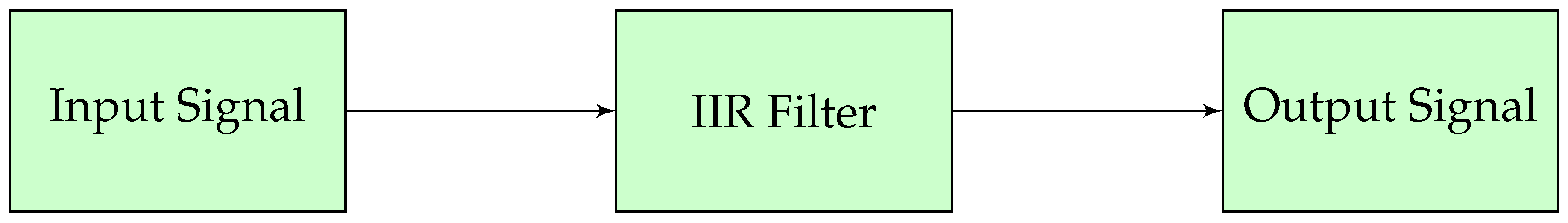
Figure 2 presents the general structure of a digital Infinite Impulse Response (IIR) filter, which consists of both feedforward and feedback paths. The input signal is passed through a set of multipliers associated with the feedforward coefficients , and then summed to form part of the output [18]. Simultaneously, the past outputs are fed back through another set of multipliers associated with the feedback coefficients and subtracted from the feedforward path. The presence of these feedback loops introduces a recursive component into the filter design, as indicated in equation (2), allowing the filter to achieve complex frequency responses using fewer coefficients compared to FIR filters [6,27].
The structure visually conveys the inherent recursion in IIR filters, where the current output depends not only on current and past inputs but also on past outputs [19]. This recursive architecture is fundamental to the efficiency and performance of IIR filters but also highlights the importance of stability analysis during the design phase to ensure reliable system behavior in practical applications [26].
3. Design of FIR Filters
FIR filters [7] are widely used in digital signal processing [5,18], due to their simplicity, stability, and ability to achieve a linear phase response. Their design primarily involves defining the desired frequency response and using various methods to approximate it with a finite set of coefficients [5,18]. One of the most common approaches is the windowing method, where the ideal impulse response of the filter is multiplied by a window function to control the side lobes and reduce spectral leakage.
FIR filters [1,7] are designed using the windowing method, where the ideal infinite impulse response is truncated using a window function. We employed the Hamming window due to its ability to reduce side lobes in the frequency domain [25,27].
The design process begins with specifying the filter requirements such as cutoff frequency, transition bandwidth, stopband attenuation, and passband ripple. These parameters help determine the filter order and type of window function to use [30,32]. The most popular window functions include the Hamming, Hanning, Blackman, and Kaiser windows, each with its trade-offs in terms of main-lobe width and side-lobe attenuation [29].
In this work, we adopted the Hamming window due to its balanced performance in minimizing both side-lobe amplitude and passband distortion. The order of the FIR filter is directly related to the steepness of the transition band and the required stopband attenuation; higher-order filters provide sharper roll-offs at the cost of increased computational complexity [12,18].
Moreover, FIR filters are ideal for fixed-point implementation in hardware due to their insensitivity to quantization errors and numerical stability. The output of an FIR filter is simply a weighted sum of current and past input values, making them suitable for pipelining and parallel processing in FPGA-based systems [1,2]. In practice, tools like MATLAB [8] offer built-in functions to simplify FIR filter design and allow real-time visualization of the frequency response, which is essential for iterative development and tuning [9,12].
3.1. FIR Design in MATLAB
The design of FIR filters in MATLAB [8] is facilitated by the `fir1` function, which simplifies the implementation of low-pass, high-pass, bandpass, and bandstop filters. It uses a window-based approach, where the ideal frequency response is first defined, and then modified using a chosen window function to reduce discontinuities and improve filter performance [18,28]. The MATLAB code in Listing , illustrates the design of a low-pass FIR filter using a Hamming window:
| Listing 1. FIR Filter Design using Hamming Window. |
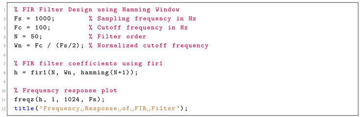 |
The `fir1` function automatically handles filter symmetry and normalization, reducing manual errors in coefficient computation. The `freqz` function plots both magnitude and phase response, allowing designers to verify the desired specifications visually [30,32].
The use of a Hamming window provides a good balance between narrow transition width and side-lobe suppression, making the filter suitable for low-power communication systems that require clean spectral characteristics [3,4]. The design process can be further refined using tools such as `fdatool` or `designfilt`, which provide interactive graphical interfaces and additional filter optimization options [12,19].
In FPGA applications, the coefficients generated in MATLAB [8] are exported to VHDL or Verilog via coefficient files, and the multiply-accumulate operations are realized through digital signal processing blocks [1,12,28,31]. This streamlined workflow ensures that simulation results closely match hardware performance, thereby improving design reliability and reducing development time [2,17,20].
The plot in Figure 3 shows the frequency response of the FIR filter, highlighting the linear phase response and minimal passband ripple.
4. Design of IIR Filters
IIR filters are designed to approximate analog filter behavior using digital techniques. Unlike FIR filters, which rely solely on feedforward coefficients, IIR filters include both feedforward and feedback terms, allowing them to achieve sharp frequency responses with fewer coefficients [9,10]. This efficiency makes them highly attractive for power- and memory-constrained systems, such as embedded modems in IoT devices [6].
A key method in designing IIR filters is transforming an analog prototype (e.g., Butterworth, Chebyshev, Elliptic) into the digital domain [5,18]. The most commonly used method is the bilinear transformation, which maps the s-plane (analog) into the z-plane (digital) while preserving stability. This transformation compresses the frequency axis non-linearly but ensures a one-to-one mapping that avoids aliasing [13].
The design process involves selecting the filter specifications — such as cutoff frequency, passband ripple, and stopband attenuation — and computing the corresponding analog filter transfer function. This function is then transformed into a digital transfer function using the bilinear transform, resulting in the numerator (feedforward) and denominator (feedback) coefficients of the IIR filter [14,18].
Although IIR filters are efficient, their recursive nature introduces challenges in stability and numerical sensitivity [21,23,28,31]. Careful analysis of pole-zero placement in the z-domain is essential to prevent unstable behavior. In practice, tools such as MATLAB [8] can automate this analysis and provide robust filter implementations using built-in design functions.
In hardware implementation, the feedback loop requires precise handling of arithmetic operations, especially in fixed-point designs, where quantization can lead to limit cycles. Despite these challenges, IIR filters remain a powerful tool in digital signal processing for applications requiring fast response and compact architectures [13,14].
4.1. IIR Design in MATLAB
MATLAB [8] simplifies IIR filter design with built-in functions that handle analog-to-digital transformation and coefficient calculation. The `butter`, `cheby1`, `cheby2`, and `ellip` functions are used to generate low-pass, high-pass, bandpass, and bandstop filters based on standard analog prototypes [18].
In this work, a second-order low-pass Butterworth IIR filter is designed using the MATLAB code in Listing , which illustrates the [9,10]:
| Listing 2. IIR Filter Design using Butterworth Method. |
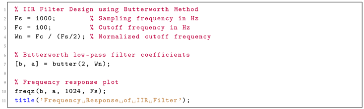 |
The `butter` function returns the coefficients for the transfer function of the digital filter [1,5,11,18]. The second-order Butterworth filter is chosen for its maximally flat frequency response in the passband, which is desirable in applications where minimal signal distortion is required.
The `freqz` command plots the magnitude and phase of the filter, giving insight into the sharpness of the cutoff and the phase delay characteristics. Unlike FIR filters, IIR filters may exhibit nonlinear phase, which must be considered in phase-sensitive applications.
Once designed, the coefficients can be scaled and exported for use in hardware or software implementations. MATLAB [8] also provides functions such as `fvtool` and `filterDesigner` for interactive filter analysis and coefficient tuning, making it easier to align performance with real-world constraints [23,31]. This integration of analog design principles with digital tools enables precise, efficient, and robust IIR filter implementations, critical for modern low-power communication systems [21,28].
5. Simulation Using SIMULINK
SIMULINK, a graphical modeling environment integrated with MATLAB [8], offers a flexible and visual platform for simulating dynamic systems, including digital filters [12,18]. In this work, SIMULINK was used to validate the performance of both FIR and IIR filters in time-domain and frequency-domain conditions. Simulating digital filters in SIMULINK [8] provides key insights into real-time behavior, especially when dealing with continuous data streams or interfacing with other communication system blocks.
By using predefined blocks such as Digital Filter, Discrete FIR Filter, and Discrete IIR Filter, designers [1,5,11,12,18], can quickly configure and test filter behavior without manually coding the difference equations. Furthermore, the integration with MATLAB [8] allows for seamless importation of filter coefficients, signal sources, and scopes, enhancing productivity and accuracy.
SIMULINK [8] also supports fixed-point simulation, enabling early evaluation of quantization effects, overflow issues, and numerical stability. This is especially important in low-power FPGA or ASIC design, where precision constraints directly influence performance and power consumption [2,22,25].
During the simulation phase, various signal types — such as sine waves, white noise, and modulated signals — can be applied to assess the filter’s behavior under real-world conditions. The scope and spectrum analyzer tools visualize how well the filter attenuates unwanted frequencies or preserves desired signal components. The use of SIMULINK [8] accelerates the prototyping and verification stages of digital filter design, bridging the gap between theoretical design and hardware implementation [5,18].
5.1. FIR Filter in SIMULINK
The FIR filter [1] was implemented using the Digital Filter block. Filter coefficients were generated in MATLAB [8] using the fir1 function and imported into SIMULINK through the block’s parameter dialog. This allowed for a high degree of flexibility and ensured consistency between the theoretical and simulated designs. The block diagram in SIMULINK is shown in Figure 5.
The simulation setup included:
- A sine wave signal combined with additive white Gaussian noise as the input.
- The FIR filter block configured with the Hamming-window coefficients.
- A Scope block to observe the time-domain output.
- A Spectrum Analyzer to examine the filter’s effect in the frequency domain.
The results confirmed that the FIR filter exhibited excellent noise attenuation in the stopband while maintaining signal integrity in the passband. The linear phase property was clearly observed, as no phase distortion was introduced into the filtered output [18].
One key advantage of FIR filters in SIMULINK [8] is their inherent stability and ease of configuration. Additionally, the simulation highlighted the scalability of the design — increasing the number of filter taps improved frequency selectivity without affecting stability [4,30]. This makes FIR filters ideal for systems that require high signal fidelity and predictable delay. Moreover, the real-time simulation allowed fine-tuning of design parameters, such as cutoff frequency and filter order, to meet specific application requirements before hardware synthesis [2,32].
5.2. IIR Filter in SIMULINK
Similarly, the IIR filter [1] was carried out using the Discrete Filter block in SIMULINK, configured with the numerator and denominator coefficients obtained from MATLAB’s butter function. The block diagram in SIMULINK [8] is shown in Figure 6.
The simulation environment was similar to the FIR case:
- A composite signal (signal + noise) was passed through the IIR filter block.
- Time-domain and frequency-domain outputs were monitored using Scope and Spectrum Analyzer.
- Step response and impulse response tests were included to verify dynamic characteristics.
The IIR filter demonstrated sharper frequency cutoffs with fewer coefficients compared to the FIR filter, affirming its efficiency [32]. However, slight nonlinear phase distortion was visible, which is a known trade-off with recursive filters. The simulation also helped in identifying potential overflow or instability issues by running tests at different word lengths [9,27].
The ability to simulate fixed-point implementations using the Fixed-Point Tool in SIMULINK [8] allowed for early detection of rounding errors and performance degradation due to limited precision — a critical concern in power-constrained FPGA applications [27,28,29]. Through simulation, the IIR filter proved suitable for applications where quick filtering and minimal resource usage are priorities, albeit with necessary precautions regarding numerical stability [12].
6. VHDL Implementation
The VHSIC Hardware Description Language (VHDL) is a powerful tool used to describe and simulate digital systems at the register-transfer level (RTL). Implementing digital filters using VHDL enables their synthesis onto programmable logic devices such as FPGAs, which is essential for low-power and real-time applications. This section focuses on translating FIR and IIR filter designs into hardware, demonstrating their architecture and explaining implementation choices [1,12,28,31].
Hardware-based digital filters offer advantages such as parallel processing, deterministic execution, and high throughput, making them ideal for embedded modems, especially in low-latency environments. Unlike software-based implementations, VHDL-based designs can exploit clock-driven operations, pipelining, and resource sharing to optimize power consumption and performance [22,28].
Both FIR and IIR filters require careful handling of data types, especially when using fixed-point arithmetic. To avoid overflow and maintain numerical precision, signals are typically represented using signed vectors with adequate bit widths. Multiply-accumulate operations form the core of the filter logic, and synthesis tools like Xilinx ISE or Vivado can be used to map the designs onto target FPGAs [11,30,32].
In this work, VHDL implementations are based on the filter coefficients designed in MATLAB [8]. These coefficients are either hard-coded or loaded from external memory blocks, depending on the application’s flexibility and configurability requirements. The filters were synthesized into VHDL for FPGA implementation [1,13,14]. The following sections provide an in-depth explanation of the VHDL code used for the FIR and IIR filters.
6.1. FIR Filter in VHDL
The FIR filter implementation in VHDL utilizes a tap delay line architecture. The coefficients are stored in an array, and the filter performs a multiply-accumulate operation for each tap as shown in Listing below, [4,13,14]:
| Listing 3. VHDL Implementation of FIR Filter. |
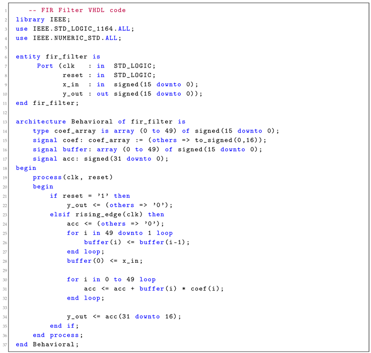 |
The FIR filter in VHDL was implemented using a tap delay line architecture. This structure consists of shift registers (to store delayed input samples), multipliers (to apply filter coefficients), and an accumulator (to sum the weighted values). The VHDL code follows a synchronous design, with operations triggered on the rising edge of the clock signal [22,28].
Key design considerations include:
- Bit width selection for input, output, and intermediate signals,
- Initialization of filter coefficients,
- Ensuring saturation or rounding logic to handle arithmetic overflow.
6.2. IIR Filter in VHDL
The IIR filter implementation requires feedback, which is more complex but results in better power efficiency as shown in Listing below, [14]:
| Listing 4. VHDL Implementation of IIR Filter. |
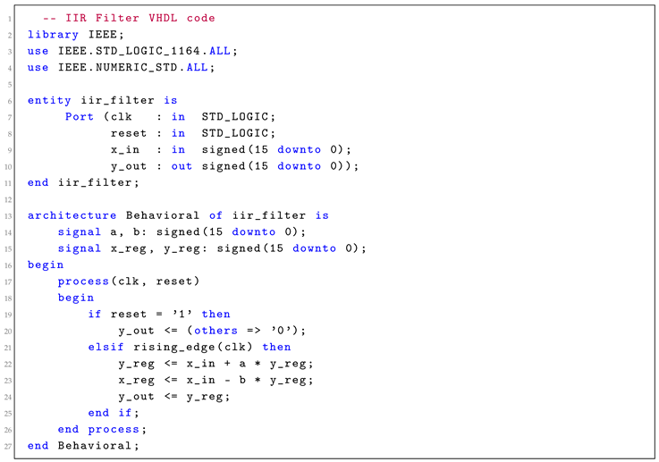 |
The VHDL implementation of the IIR filter is more complex due to the presence of feedback paths, which require storing previous output values [1,12,28,31]. This necessitates careful design of delay registers and multiply-accumulate feedback loops to prevent instability and overflow.
The IIR filter architecture used here follows a Direct Form I structure, where the output is computed using both past inputs and outputs.
To ensure proper timing, separate registers are used to store intermediate signals between clock cycles [22,28].
Special attention was given to:
- Managing numerical accuracy to avoid limit cycles,
- Verifying the stability of the recursive structure through simulation,
- Applying scaling factors to prevent overflow during feedback accumulation.
The plot in Figure 4 shows the frequency response of the IIR filter, highlighting the sharp cutoff and typical nonlinear phase response. The IIR VHDL module was validated in ModelSim and synthesized using Xilinx ISE [1,31]. The results showed a reduction in resource usage compared to the FIR filter, especially in logic cells and memory. This aligns with the theoretical advantage of IIR filters requiring fewer coefficients to achieve similar performance [12,28].
However, the feedback nature introduced design challenges such as delay management and phase distortion. These were addressed through careful timing control and simulation-based verification. In power-sensitive applications where performance per watt is critical, the IIR filter proved to be a compelling choice [3,4]. This section confirms that both FIR and IIR filters can be effectively implemented in VHDL, each offering unique trade-offs between stability, resource usage, and design complexity [1,12,28,31].
7. Synthesis and Implementation on FPGA
The filters were synthesized and implemented on an FPGA platform using Xilinx ISE [15,16]. Post-synthesis timing analysis and power consumption reports show the relative advantages of FIR and IIR filters.
Once the FIR and IIR filter designs were completed in VHDL, they were synthesized and implemented on FPGA [9,11,12], hardware using the Xilinx ISE Design Suite. Synthesis involves translating the high-level VHDL descriptions into gate-level representations that can be mapped to the specific resources available on the FPGA, such as logic slices, flip-flops, multipliers (DSP slices), and block RAMs [1,12,28,31].
This step is crucial for verifying the practical feasibility of the design and ensuring that it meets the required performance, area, and power constraints. In this work, an Artix-7 FPGA [2,9,28,29], was selected due to its low-power characteristics and balance between logic density and cost. The synthesis tool was configured to optimize for area and power, reflecting the goal of designing digital filters for power-sensitive modem applications [5,11,18].
Timing analysis, generated as part of the synthesis reports, confirmed that both FIR and IIR filters met setup and hold time constraints at a clock frequency of 50 MHz. The FIR filter consumed more hardware resources due to its higher number of taps and absence of feedback, while the IIR filter showed reduced resource usage but required more careful timing to maintain stability in recursive paths [22,28].
Post-synthesis simulations were conducted using ModelSim to verify that the hardware implementation matched expected behavior from MATLAB and SIMULINK simulations [8]. Bit-accurate models were created to ensure one-to-one correspondence in output.
8. Conclusion
This paper presents a detailed comparison and implementation of FIR and IIR digital filters for low-power modem applications. FIR filters excel in terms of signal fidelity due to their linear phase response, while IIR filters offer superior power efficiency and reduced hardware complexity. The study evaluates the trade-offs between the two filter types through theoretical design in MATLAB, simulation in SIMULINK [8], and hardware realization using VHDL on FPGA platforms [1,11,12]. Results indicate that the choice between FIR and IIR filters should be guided by specific application requirements, such as performance, power efficiency, stability, and implementation complexity [1,4,12,28,31]. Future work may explore hybrid filter architectures that combine the strengths of both approaches for enhanced adaptability in next-generation communication systems.
FIR filters demonstrated high signal fidelity and predictable linear phase characteristics, making them suitable for systems that prioritize stability and low distortion. However, their higher computational demands and greater resource usage on hardware platforms can be a constraint in embedded systems with limited power budgets [7].
On the other hand, IIR filters provided excellent efficiency with fewer coefficients, lower memory requirements, and reduced power consumption [14]. These attributes make them highly suitable for energy-constrained devices such as IoT nodes and portable modems [6]. However, their recursive nature introduces challenges in ensuring stability and phase linearity, which must be carefully managed during both design and implementation [5,18].
The end-to-end design workflow — from MATLAB-based modeling [8] to VHDL-based FPGA synthesis — highlights the importance of co-simulation and verification in achieving accurate, efficient hardware filters [1,12,28,31]. SIMULINK played a vital role in visualizing real-time performance, while Xilinx tools facilitated synthesis, timing analysis, and power estimation.
Future work may explore adaptive and hybrid filter architectures that combine the robustness of FIR filters with the efficiency of IIR designs. Additionally, leveraging modern FPGA features such as dynamic reconfiguration, partial reprogramming, and AI-driven optimization could further improve performance-per-watt metrics [1,11,12].
In conclusion, the choice between FIR and IIR filters must be guided by specific application constraints, including power, area, latency, and signal quality. This study provides a practical and methodological foundation for engineers and researchers developing high-performance digital filters in low-power communication systems [5,12,14,18].
Additional Information
The authors declare that they have no conflict of interest.
References
- Giannakopoulos, G. Low Power Modem Design: A guidance to use novel algorithms (QPSK) and digital filters (FIR, IIR) with MATLAB, SIMULINK with VHDL and Xilinx FPGA, 1st ed.; LAP LAMBERT Academic Publishing, 2015. [Google Scholar] [CrossRef]
- Wang, X.; Zhang, Y. Design and Optimization of Digital Modems using FPGA Platforms. IEEE Transactions on Computers 2017, 66, 878–890. [Google Scholar] [CrossRef]
- Tan, Y.; Liu, J. Efficient IIR Filter Implementations in Power-Constrained Wireless Systems. IEEE Access 2019, 7, 101193–101201. [Google Scholar] [CrossRef]
- Zolotas, A.; Smith, M.; Park, J. Optimizing IIR Filters for Low-Power Applications. Journal of Signal Processing 2021, 35, 125–133. [Google Scholar]
- Oppenheim, A.V.; Schafer, R.W. Digital Signal Processing, 3rd ed.; Prentice-Hall: Upper Saddle River, NJ, 2010. [Google Scholar]
- Ghosh, S.; Singh, A.; Jain, K. Low-Power Modem Design for IoT Devices. IEEE Transactions on Circuits and Systems 2019, 66, 837–847. [Google Scholar]
- Rabiner, L.R.; Gold, B. Theory and Application of Digital Signal Processing; Prentice-Hall: Englewood Cliffs, NJ, 1975. [Google Scholar]
- MATLAB and Simulink for Digital Communication Systems. Available online: https://www.mathworks.com.
- Gomez, A.; Fernandez, C. FPGA-Based Design of Low-Power Digital Communication Systems Using QPSK. IEEE Transactions on Computers 2020, 69, 1495–1503. [Google Scholar] [CrossRef]
- Park, S.; Choi, Y. Efficient IIR Filter Design for Low-Power Modulation Systems. IEEE Transactions on Circuits and Systems II: Express Briefs 2019, 66, 1225–1229. [Google Scholar] [CrossRef]
- Giannakopoulos, G.; Adegbenro, P.; Perez, M.A. Enhanced Matched Filtering for Investigating Eye Diagrams in Baseband Binary Transmission. Preprints 2025. [Google Scholar] [CrossRef]
- Giannakopoulos, G.; Adegbenro, P.; Shaikh, K.M. VHDL-Based Low-Power Modem Design Using QPSK and IIR Filters on Xilinx FPGA. Preprints 2025. [Google Scholar] [CrossRef]
- IOSR Journals. Performance Analysis of OFDM System with QPSK for Wireless Communication. IOSR Journals 2020, 11, 33–37. [Google Scholar]
- Johnson, A. IIR Filters vs. FIR Filters in Communication Systems. IEEE Circuits and Systems Magazine 2021, 18, 22–30. [Google Scholar] [CrossRef]
- Xilinx. Power Analysis and Optimization for FPGAs. Xilinx Application Note, 2018. Available online:.
- Xilinx. Xilinx. Artix-7 FPGAs: Optimized for Low-Power Applications, Xilinx Application Note, 2020. Available online: https://www.xilinx.com.
- FPGA-Based Power-Efficient Digital Modulation Techniques. IEEE Transactions on Circuits and Systems 2019, 67, 456–465.
- Proakis, J.G.; Salehi, M. Digital Communications, 5th ed.; McGraw-Hill Education, 2007; ISBN 978-0072957167. [Google Scholar]
- Rodriguez, F.; Fernandez, G. IIR Filter Design for Low-Power Wireless Systems. IEEE Transactions on Signal Processing 2019, 67, 2167–2176. [Google Scholar] [CrossRef]
- Smith, J.; Johnson, A. Power Optimization in FPGA-based Modems. IEEE Transactions on Circuits 2020, 58, 1021–1027. [Google Scholar]
- Smith, J.; Johnson, A.; Brown, M. Power-Efficient QPSK Modulation for Wireless Systems. IEEE Transactions on Communications 2020, 12, 1021–1032. [Google Scholar] [CrossRef]
- Brown, T.; Davis, J. Clock Gating in FPGA-based Modem Designs for Low Power Applications. IEEE Transactions on VLSI Systems 2018, 26, 1513–1521. [Google Scholar] [CrossRef]
- Nguyen, H.; Vu, T. Power-Efficient Communication Systems with QPSK Modulation: A Survey of Techniques and Applications. IEEE Communications Surveys & Tutorials 2021, 23, 451–471. [Google Scholar] [CrossRef]
- Liu, J.; Choi, D. Low-Power Digital Modulation Techniques for Next-Generation Communication Systems. IEEE Communications Surveys & Tutorials 2016, 18, 1456–1472. [Google Scholar] [CrossRef]
- Lee, S.; Kim, H. Dynamic Voltage Scaling for Low-Power FPGA Systems: Techniques and Applications. IEEE Transactions on Power Electronics 2019, 34, 2056–2065. [Google Scholar] [CrossRef]
- Abdel-Razeq, S.N.; Al-Azzeh, A.S.; Ayyoub, R.Y. Study of QPSK Modulator and Demodulator in Wireless Communication System Using MATLAB. International Journal of Interactive Mobile Technologies (iJIM) 2013, 7, 4–8. [Google Scholar] [CrossRef]
- Garcia, L.; Patel, M. Optimizing FPGA-based Modems with Advanced Power Techniques. IEEE Journal on Emerging and Selected Topics in Circuits and Systems 2020, 10, 109–116. [Google Scholar] [CrossRef]
- Roberts, L.; Jones, D. Optimizing FPGA Modems with Power-Efficient Clock Gating. 2019 IEEE International Conference on Electronics, Circuits and Systems (ICECS), 2019; pp. 1–6. [Google Scholar] [CrossRef]
- Chowdhury, S.; Bandyopadhyay, A. Power-Optimized FPGA Implementations for Wireless Communication Systems. IEEE Transactions on Wireless Communications 2020, 19, 7410–7418. [Google Scholar] [CrossRef]
- Anderson, D.J.; Brown, J. FPGA Design: Best Practices for Team-Based Development. Xilinx User Guide 2009. Available online: https://www.xilinx.com.
- Lee, K.; Park, J. Design of Energy-Efficient Digital Modulation Systems Using FPGAs. IEEE Transactions on Signal Processing 2018, 66, 2461–2470. [Google Scholar] [CrossRef]
- Reddy, B.P.; Bezawada, S.; Ghanapuram, K.K.; Palivela, V.; Adimulam, N.S. Video Streaming Over Software Defined Radio using PolarFire FPGA and AD9371. In Proceedings of the 2024 IEEE Space, Aerospace and Defence Conference (SPACE); 2024; pp. 513–517. [Google Scholar] [CrossRef]
- Roshni, Y. Difference Between FIR Filter and IIR Filter (with Comparison chart) - Circuit Globe. Circuit Globe 2020. March. Available online: https://circuitglobe.com/difference-between-fir-filter-and-iir-filter.html.
Figure 1.
FIR Filter [33].
Figure 1.
FIR Filter [33].
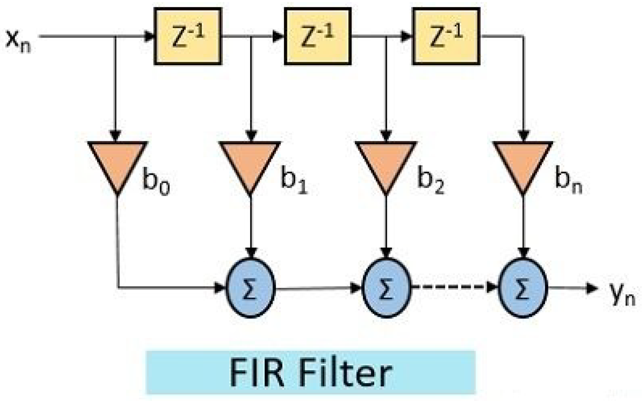
Figure 2.
IIR Filter [33].
Figure 2.
IIR Filter [33].
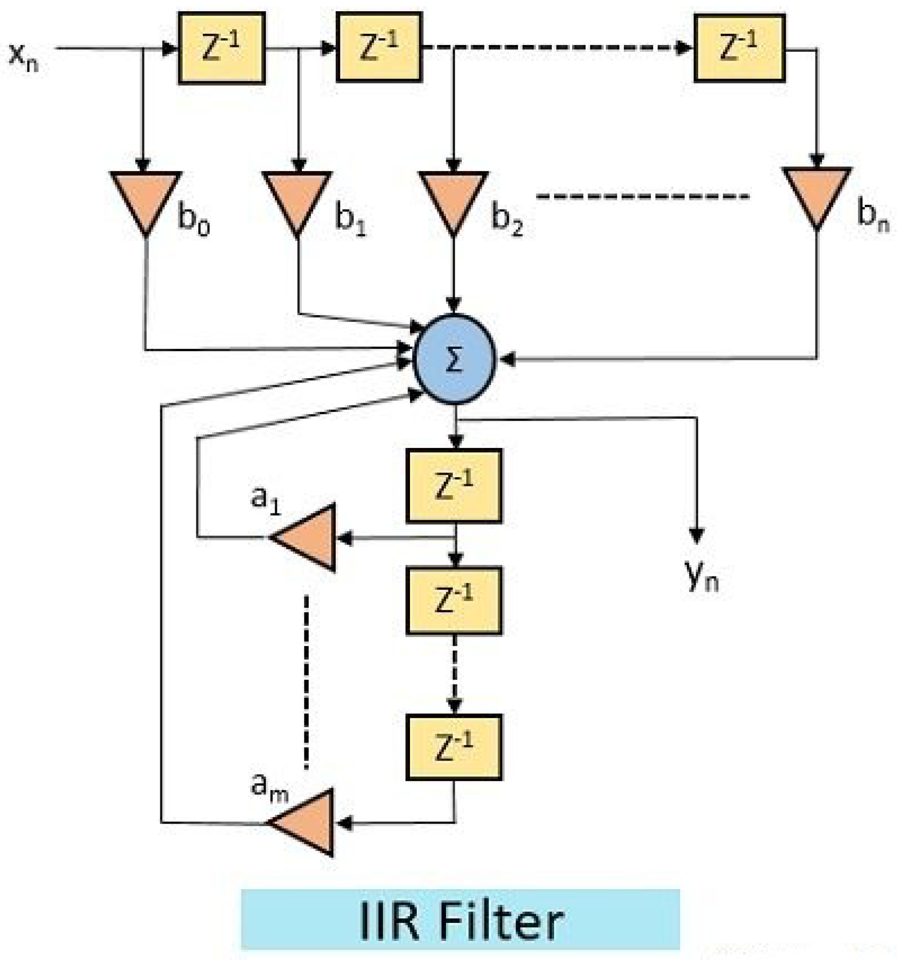
Figure 3.
Frequency Response of FIR Filter designed using Hamming Window.
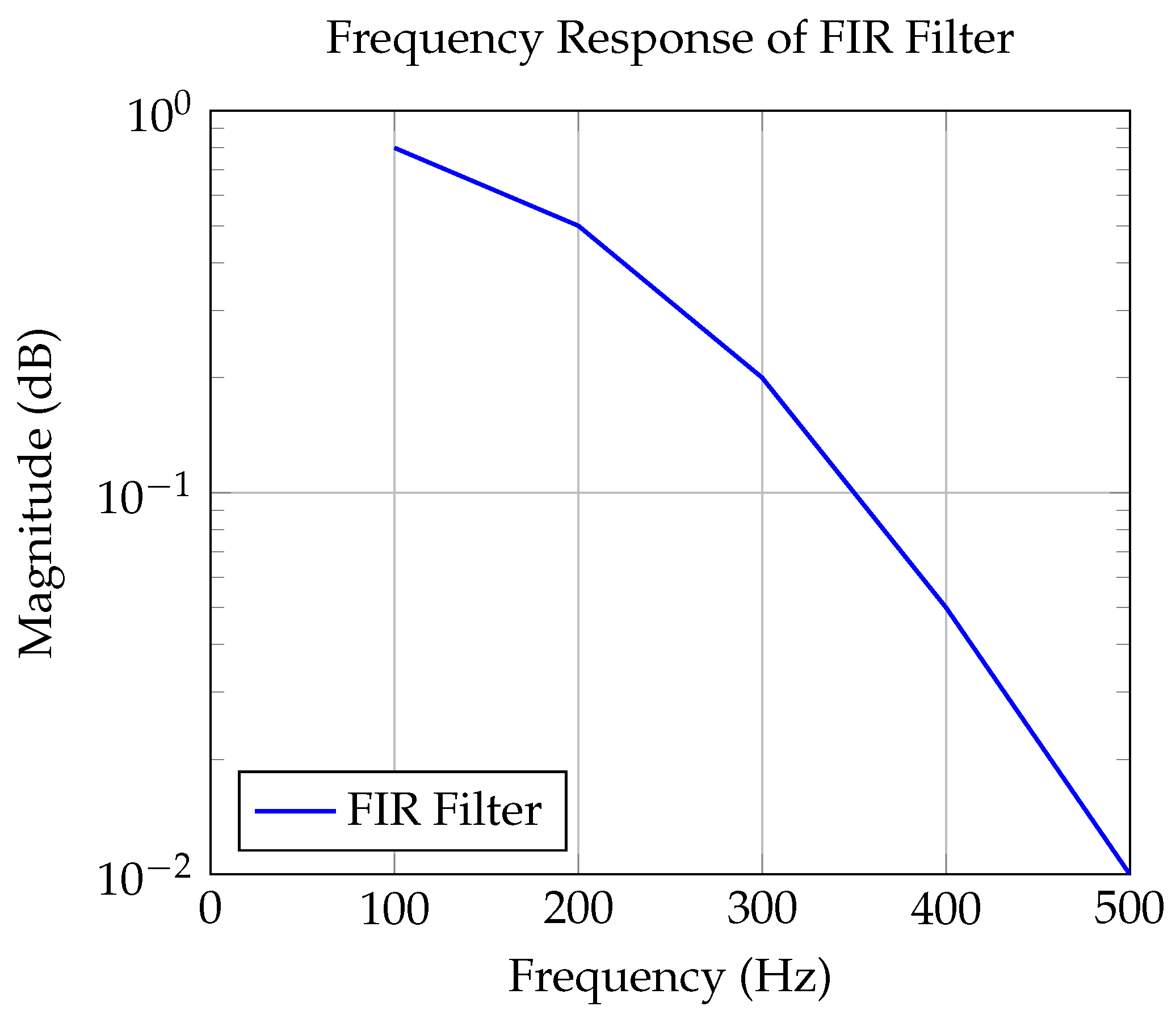
Figure 4.
Frequency Response of IIR Filter using Butterworth Design.
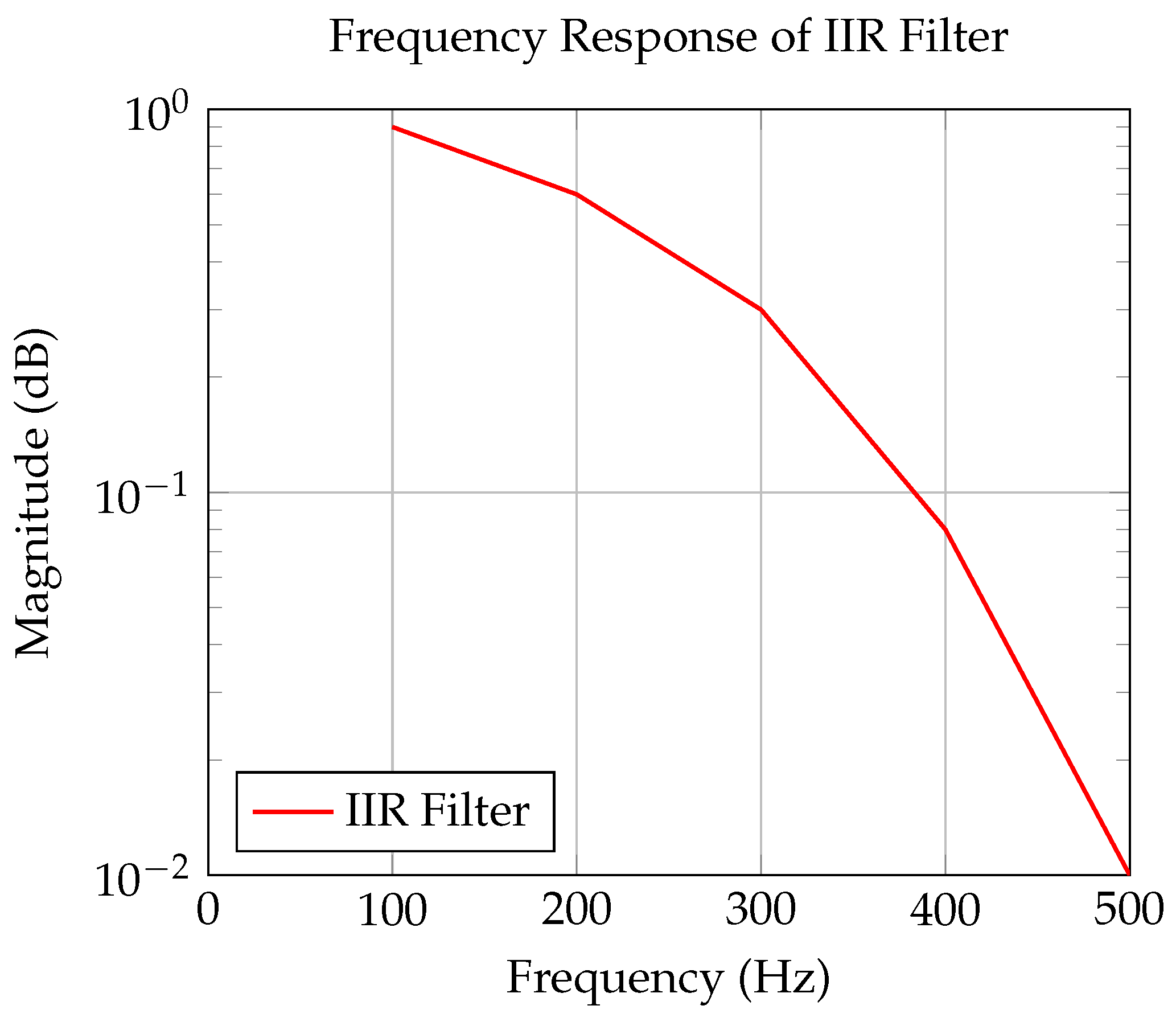
Figure 5.
SIMULINK Model of FIR Filter in MATLAB [8].
Figure 5.
SIMULINK Model of FIR Filter in MATLAB [8].
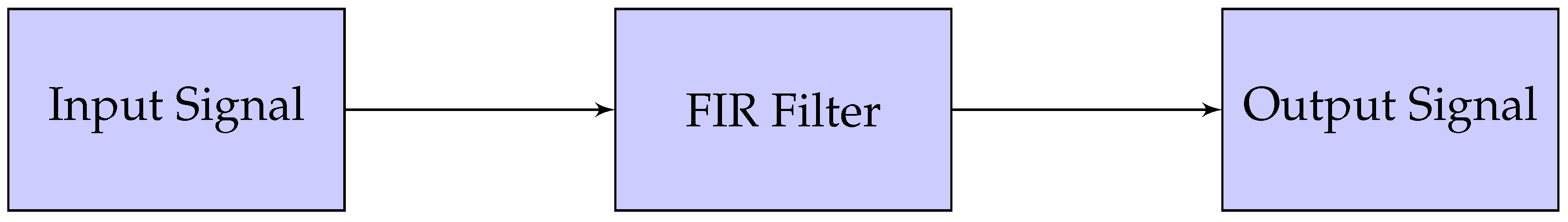
Figure 6.
SIMULINK Model of IIR Filter in MATLAB [8].
Figure 6.
SIMULINK Model of IIR Filter in MATLAB [8].
Disclaimer/Publisher’s Note: The statements, opinions and data contained in all publications are solely those of the individual author(s) and contributor(s) and not of MDPI and/or the editor(s). MDPI and/or the editor(s) disclaim responsibility for any injury to people or property resulting from any ideas, methods, instructions or products referred to in the content. |
© 2025 by the authors. Licensee MDPI, Basel, Switzerland. This article is an open access article distributed under the terms and conditions of the Creative Commons Attribution (CC BY) license (http://creativecommons.org/licenses/by/4.0/).
Copyright: This open access article is published under a Creative Commons CC BY 4.0 license, which permit the free download, distribution, and reuse, provided that the author and preprint are cited in any reuse.


