Preprint
Article

This version is not peer-reviewed.

Design, Fabrication, and Performance Study of Solar Thermoelectric Generator

Submitted:

07 February 2025

Posted:

10 February 2025

You are already at the latest version

Abstract

This project presents the design, fabrication, and performance study of a solar thermoelectric generator. Solar energy is considered one of the most effective types and sources of renewable energy. Among the available options, solar energy has predominantly been harnessed through the use of solar PV panels. However, solar PV panels are quite expensive, an alternative system is designed to utilize solar energy through thermoelectric generators. This new design is a cheaper system because it replaces solar PV panels with thermoelectric generators that can absorb heat and convert it directly into electricity through a concept known as the Seebeck effect. The Seebeck effect is based on the temperature difference between two sides. By heating the hot side of a thermoelectric material, electrons migrate from the hot side to the cooler side, thereby generating an electrical current. Since the Seebeck effect depends on higher temperature differences for more efficiency, a cooling system positioned below which will cool the cold side of the STEG, while the sun above will heat the hot side, creating a higher temperature difference and improved efficiency. This system focuses on a two-stage thermoelectric generator comprised of two modules: a lower-temperature generator and a medium-temperature generator. In accordance with the optimal operating temperature of thermoelectric materials, the medium-temperature generator is positioned on the hot side, while the lower-temperature generator is situated on the cold side. Ultimately, the performance of the two-stage STEG is assessed across various operational conditions. The primary advantage of employing a two-stage STEG is that the heat-to-electricity conversion process occurs twice as the heat passes through the two-stage STEG, resulting in higher efficiency compared to a single-stage thermoelectric generator.

Keywords: 

1. Introduction

1.1. Background of Thermoelectric Generator

The basic analysis of thermoelectric generators has been established by this research. More electricity can be produced and more waste heat can be conserved by increasing the number of modules and arranging them in arrays. But it is undeniable that there are limitations on size, weight, cost, module interface, and temperature differential that make it very difficult for practical applications [1]. Thermoelectric devices face practical difficulties in some applications due to their low thermal conductivity, which makes them unsuitable for situations where heat removal is necessary, such as heat removal from electrical devices like microprocessors, and their relatively high electrical output resistance, which increases self-heating. It might be argued that it is justifiable based on the STEG's life and manufacturing cost. It was discovered that STEG with a rectangular form produced superior outcomes [2]. The difference in temperature between the hot and cold plates is crucial to how well the STEG functions. The maximum temperature on the hot side is limited by STEG's maximum operating temperature. The solar heat absorption may be enhanced by using a better heat exchanger and a thermoelectric module that can withstand higher temperatures. Here are the major benefits of the device given below in order to comprehend the relevance of the STEG application [3].
  • Reliability - Solid-state electronics include thermoelectric generators. They are extremely dependable since they are no moving components to fail or wear out. Thermoelectric generators have an exceptionally long lifespan. As of this writing, the Voyager 1 spacecraft's thermoelectric generator has been in service for 41 years. Without any maintenance or repairs, it has logged more over 13 billion miles of the journey.
  • Quiet - It is possible to build thermoelectric generators to be absolutely quiet.
  • No Greenhouse Gases - There are no greenhouse emissions needed to run thermoelectric generators. Some technologies for energy conversion do.
  • Wide Range of Fuel Sources - The types of fuels that may be utilized to produce the necessary heat with thermoelectric generators are not constrained. This is true of many different energy conversion systems.
  • Scalability - Microwatts to kilowatts of power may be generated using thermoelectric generators.
  • Mountable in Any Orientation - In any position, the thermoelectric generator's function. Depending on how they are oriented in relation to gravity, several energy conversion devices are sensitive.
  • Operation Under high and Zero G-forces - High-G or zero-G operating conditions are also possible for thermoelectric generators. Other energy conversion systems can't, though.
  • Direct Energy Conversion - Heat is immediately converted into electricity using thermoelectric generators. When converting heat to electricity, several energy conversion systems demand intermediary processes. For instance, the thermal energy from the fuel is transformed into mechanical energy in a turbine, and the mechanical energy is subsequently transformed into electrical energy in a generator. Waste heat losses are added with each energy conversion stage. In comparison to certain other energy conversion methods, thermoelectric generators are less mechanically difficult because of this.
  • Compact Size - Compact thermoelectric generator designs are possible. Greater design freedom results from this.
Figure 1. Model of The Two Stage Thermoelectric Generator.
Preprints 148660 g001

1.2. Principle of Thermoelectric Generator

The Seebeck effect forms the foundation for the operation of a thermoelectric generator. The act of joining two junctions that are made from different materials and exposed to different temperatures results in a voltage output estimated to be around microvolts per Kelvin (μV/K). The substances employed here are referred to as thermoelectric substances, which are chosen based on their characteristics, such as thermal conductivity, electrical conductivity, Seebeck coefficient, etc [4]. The temperature difference between the opposing sides of the STEG determines the amount of power produced by the device, when one surface is kept at a higher temperature, heat is transferred to the opposite surface, thereby reducing the temperature difference. Therefore, it is necessary to construct a heat exchanger to maintain a low temperature on the opposite face. By understanding the device's behavior under varying temperature conditions, insights can be gained into its potential applications and optimization strategies [5]. Ultimately, this study aims to contribute to the advancement of thermoelectric technology, enabling the development of more efficient and reliable energy conversion systems.

1.3. Objectives of the Study

The initial concern revolves around the insufficient heat from the sun to generate a substantial temperature disparity on the hot side. Consequently, our proposal entails the utilization of a Fresnel lens to concentrate solar rays onto the hot side, thereby addressing this limitation.
The second issue pertains to the necessity of maintaining a high and sustained temperature difference between the hot and cold sides in order to attain greater efficiency. Our approach addresses this concern by initially separating the hot and cold sides through isolated chambers, ensuring that no heat escapes from the hot side chamber. Subsequently, we employ a cooling system underneath to dissipate the heat transferred to the cold side.
The third concern is that during the cooling process of the cold side, heat is dissipated into the surrounding environment, which could be used for other beneficial purposes. Our project presents a cooling system that utilizes water as a coolant for effectively cooling the cold side, thereby transferring the heat to the water. Consequently, this heated water can be employed to meet domestic requirements and serve as preheated water for industrial boiler applications. The objectives are listed below.
I.
To Design a Solar Thermoelectric Generator.
II.
To Fabricate a Solar Thermoelectric Generator.
III.
To Study the performance of a Solar Thermoelectric Generator under different temperatures.

1.4. Structure of the Thesis

The project's thesis is organized into seven (7) chapters. The first (1) chapter is the Introduction, which is divided into four sections: the Background of Thermoelectric Generator, the Principle of Thermoelectric Generator, the Objectives of the study, and the Thesis Structure. The second (2) chapter discusses the Literature Review of several papers that explain thermoelectric generators in greater detail. The Description of the model/system prototype is outlined in Chapter three (3), which is divided into five sections: Generator Specifications and Operating Parameters, Solar Tilt Angle Analysis, Configuration of STEG, Cooling System of STEG, and Heating System of STEG. Chapter four (4) discusses the Computational Methodology Implementation, the Governing Equations of Coupled Thermoelectricity, the Performance Analysis and the Environmental Impact Analysis. The Results and Discussions are explained in Chapter five (5), which provides further details on the Solar Fresnel Lens Power Output Calculation, Results, Discussions, and Comparison with other Technologies like Solar PV. Chapter six (6) is the Conclusion, which includes the Conclusion section as well as Recommendations for future work. Finally, chapter seven (7) is the References, serving as the final chapter.

2. Literature Review

Utilizing the lower temperature STEG substance known as bismuth (III) telluride (Bi2Te3) in conjunction with the moderate temperature STEG substance called skutterudite (CoAs3), G. Jeffrey and his colleagues devised a multi-dimensional finite element simulation of a thermoelectric generator (STEG). This innovative approach aimed to optimize the conversion of waste heat into useful electrical energy, a critical step towards achieving sustainable and efficient power generation. By combining the unique properties of (Bi2Te3) and (CoAs3), the researchers sought to enhance the overall performance of the STEG system, pushing the boundaries of thermoelectric technology [6]. Through rigorous simulations and testing of different fabrication variables ranging from material compositions to geometric structures as well as operating conditions, X. Wu and his team has uncovered an exciting path toward developing markedly superior thermoelectric generators. With vast potential benefits that could transform numerous applications associated with waste heat recovery systems, this groundbreaking research brings us ever closer to nurturing a healthier planet that will endure for generations to come [7].
G. Tan and his colleagues carried out extensive evaluations of the ongoing advancements in thermoelectric materials and generators. This paper provides a fully comprehensive analysis of the material used along with various techniques adopted by thermoelectric generators for increasing efficiency. And finally, drawing upon an analysis of recent advancements within these fields, such as novel alloys or nanostructured composites, this study aims to uncover untapped potential that could help improve generator performance further [8].
To facilitate the development of semiconductor systems, this study explores the numerical efficiency of concentrated thermoelectric generators using three distinct geometric types. An analysis of temperature-dependent characteristics pertaining to industrial thermoelectric materials is conducted to augment and clarify simulations. Additionally, an analogous system was established through employing the three-dimensional finite element approach [9]. This study’s investigation aims to provide valuable insights into the design and optimization of thermoelectric devices. Through examining of different geometric configurations and incorporating material properties, the study also offers a comprehensive understanding of the future potential enhancements and challenges associated with concentrated thermoelectric generators [10].
As part of their research on phase change lenses and their impact on thermoelectric generators through refraction, S. P. LeBlanc and his colleagues have emphasized the need for adequate cooling measures. Failure to effectively handle concentrated heat could lead to elevated temperatures that hinder overall efficiency. By giving priority to a reliable cooling mechanism, optimal performance can be attained [11]. J. He and his team's investigation involves exploring the intricate relationship between the phase change lenses' refractive properties and the thermoelectric generator's conversion efficiency. With a focus on enhancing the conversion of waste heat into usable electrical energy, they aim to unlock new possibilities for sustainable power generation. This endeavor requires a thorough understanding of the thermal dynamics involved, ensuring that the temperature remains within the desired range for optimal performance [12].
C. Dames and his colleagues conduct an extensive analysis of different cooling strategies, aiming to enhance thermoelectric generator efficiency by means of forced convection. Assessing both the benefits and limitations of each cooling system method, the study also presents suggestions for optimizing cooling outcomes. The researchers have also carried out a comprehensive investigation into the potential benefits that liquid, air, and hybrid cooling mechanisms offer for improving thermoelectric generator performance [13]. This research emphasizes the critical role played by thermal management practices in achieving optimum efficiency. The examination of pivotal factors like heat transfer coefficients, pressure drops, and temperature distribution has rendered essential understandings for improving cooling strategies and attaining maximal energy conversion efficiency in thermoelectric generator applications [14].
This paper addresses the challenges associated with the design and implementation of the proposed concentration solar thermoelectric generator (CTG) system. The selection of the concentration ratio plays a crucial role in optimizing the performance of the system, as higher concentrations can potentially enhance the temperature difference across the thermoelectric modules. However, it is important to strike a balance, as excessively high concentration ratios may lead to increased heat losses and thermal stresses. Additionally, the cooling technique employed for the thermoelectric materials is a key factor in maintaining their efficiency and prolonging their operational lifespan [15]. The article explores various cooling methods, such as active liquid cooling or passive air cooling, and assesses their suitability based on factors such as cost, complexity, and heat dissipation capabilities. By thoroughly examining these design considerations, this proposal aims to pave the way for the development of an efficient and reliable CTG system that can harness solar energy and convert it into usable electrical power [16].

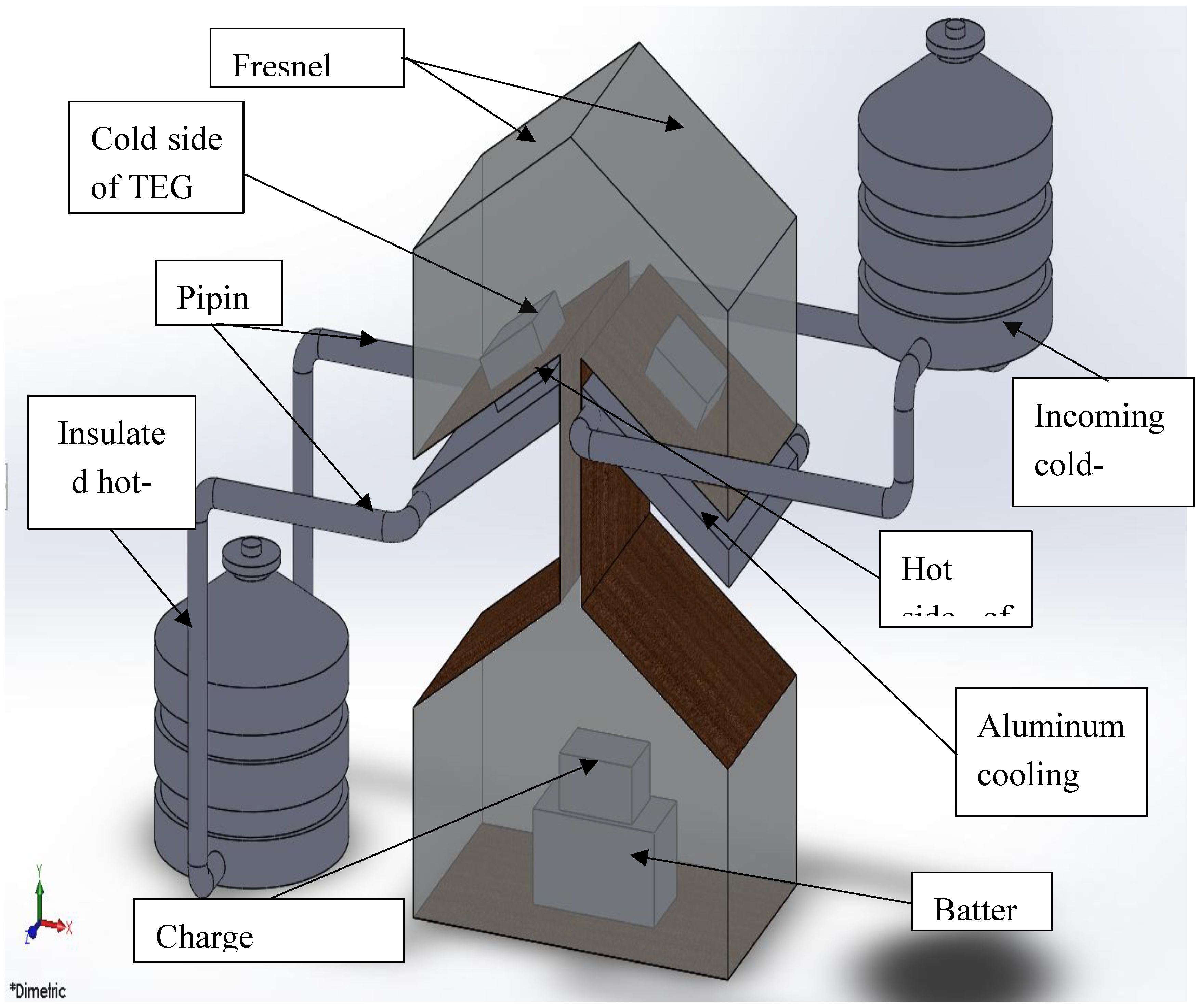
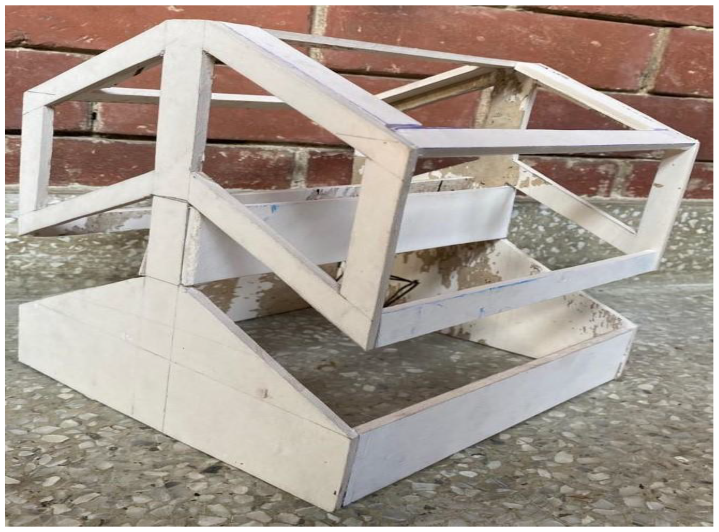
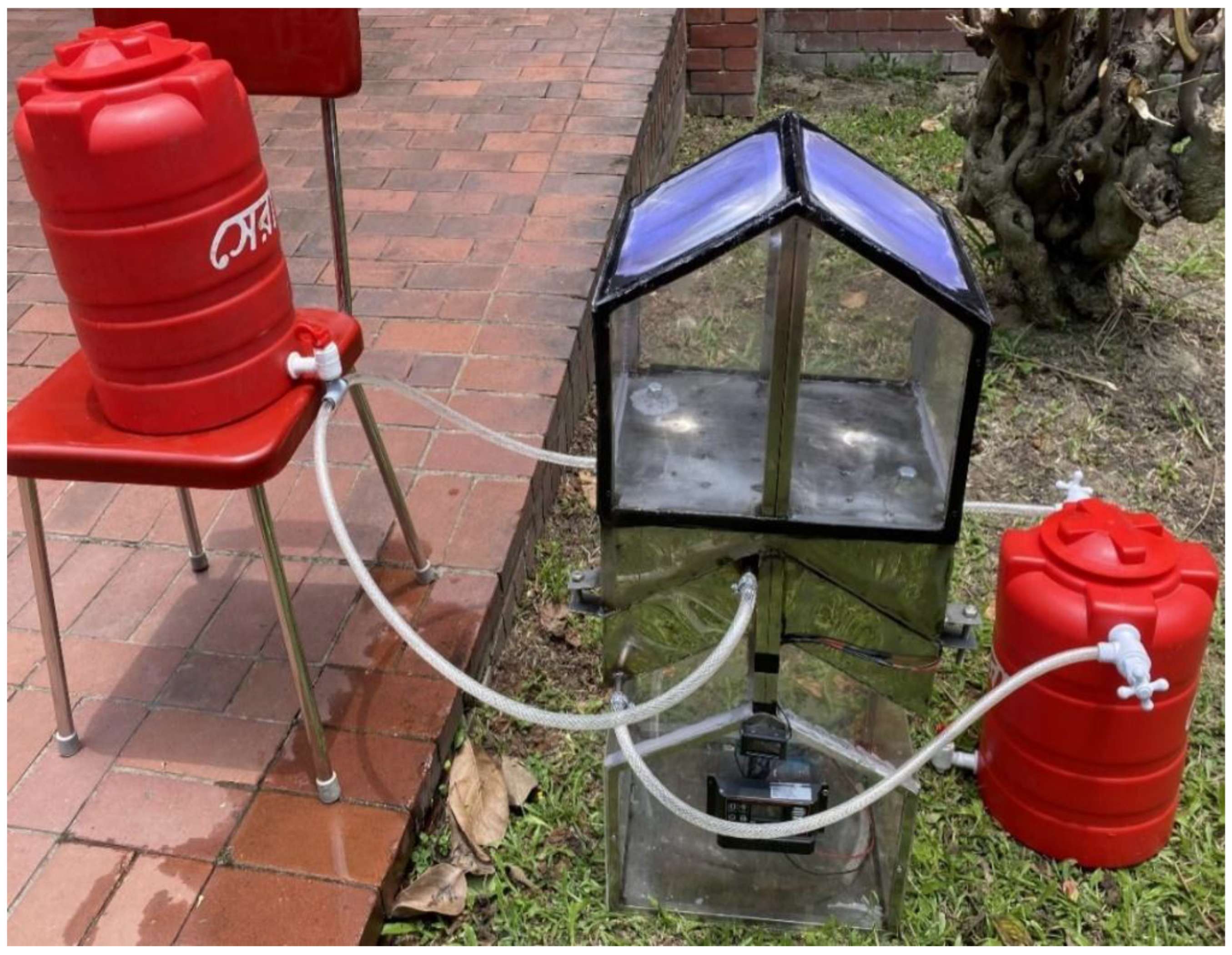
3. Description of the Model/System

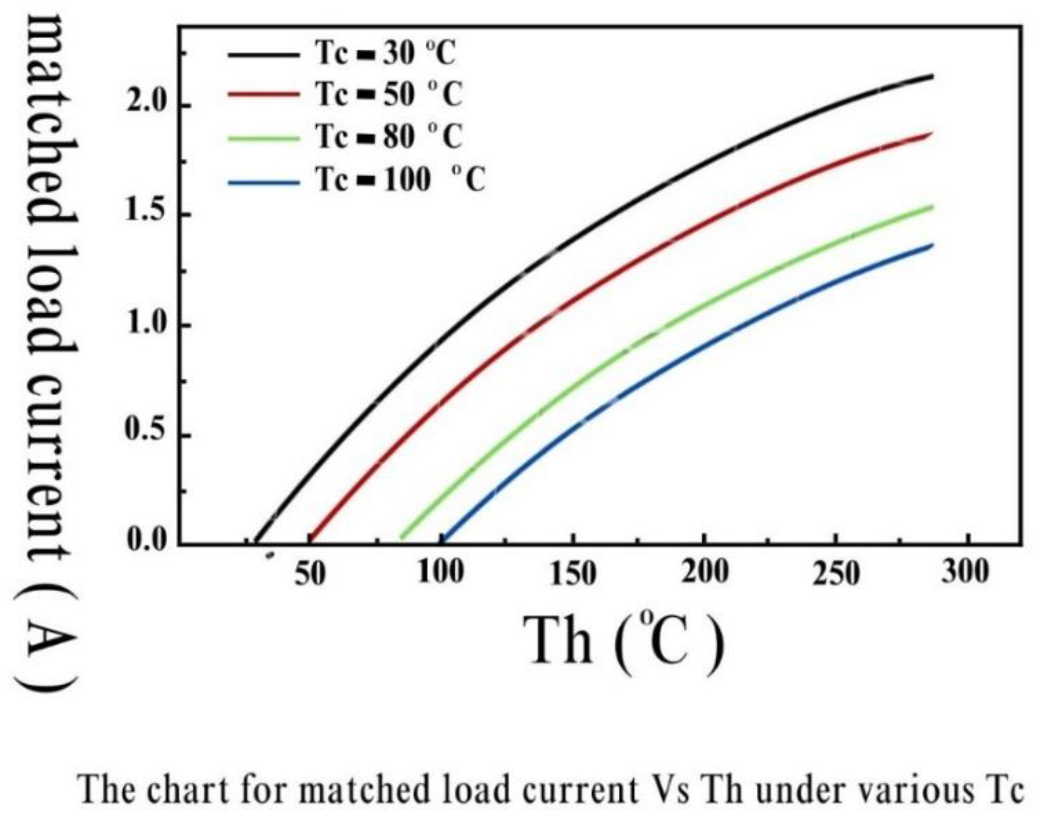
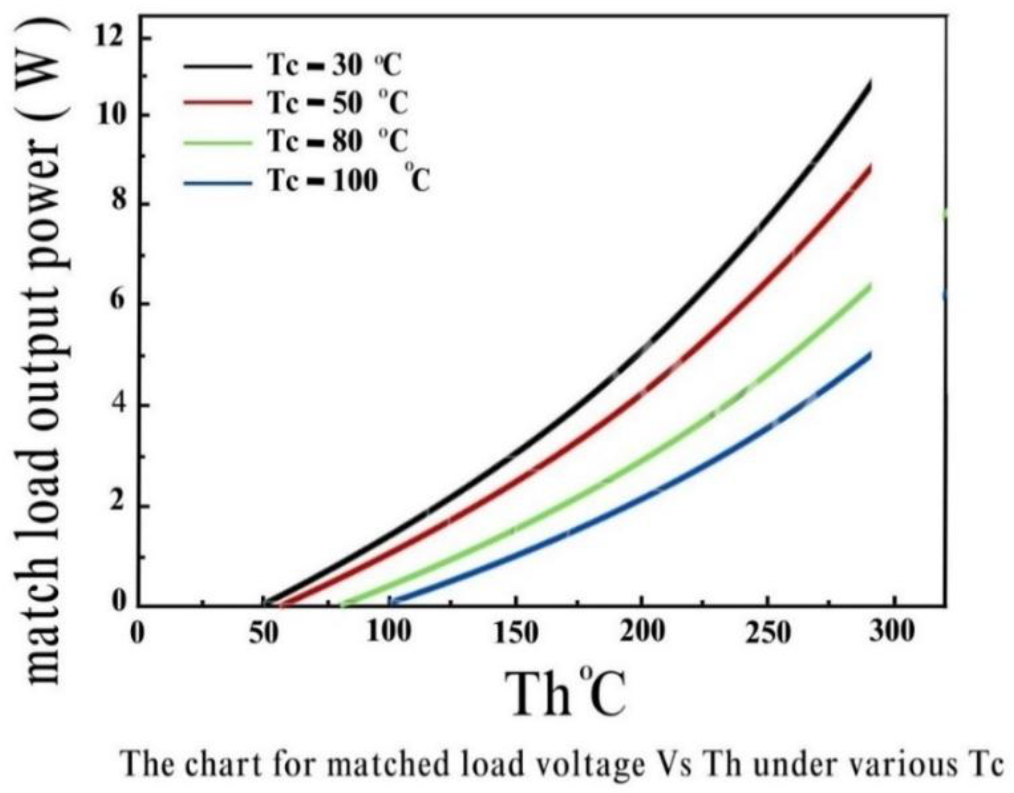
3.1. Generator Specification and Operating Parameter
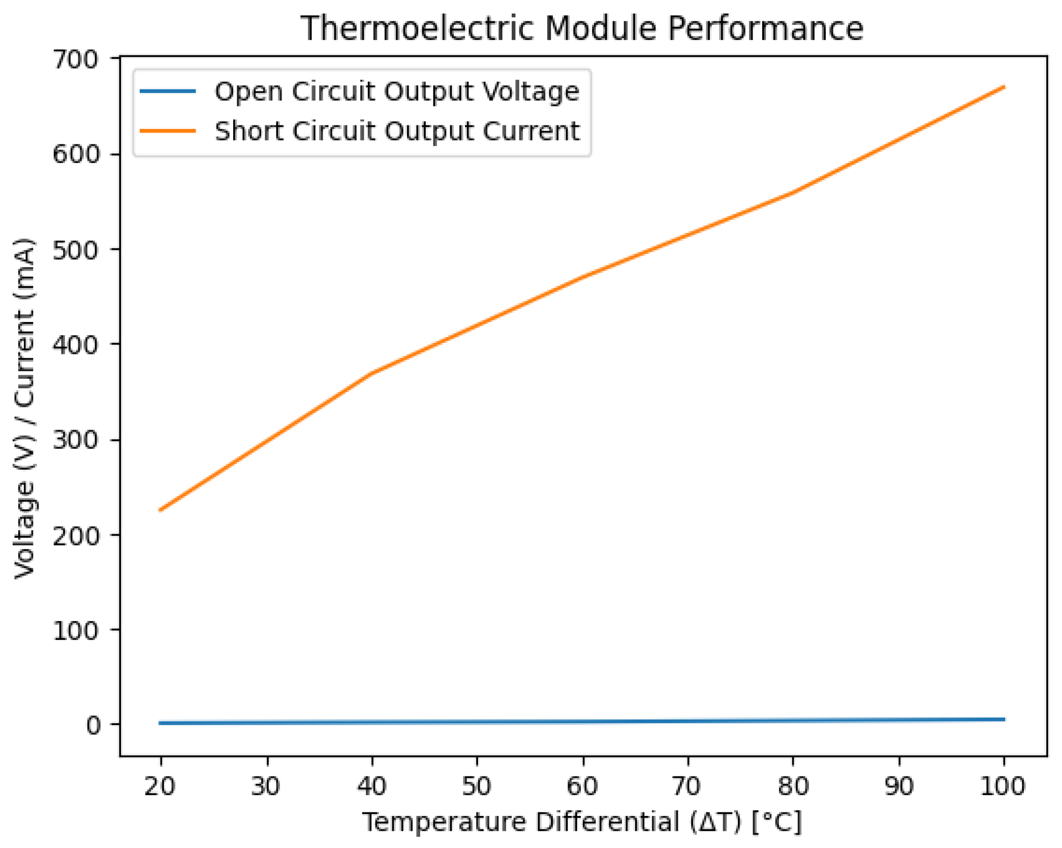
The structure and composition of the low-temperature thermoelectric generator include a one-layer, two-sided ceramic structure, bismuth telluride (Bi2Te3) as the semiconductor material, and a low-temperature solder (Tin-Bismuth Alloy) as a soldering agent. The bismuth telluride material can tolerate temperatures as high as 150°C and has a typical operating temperature range of -60 to 130°C. The specifications of the low-temperature thermoelectric generator are provided in the Table 1 below [17].
Thermoelectric parameters:
i.
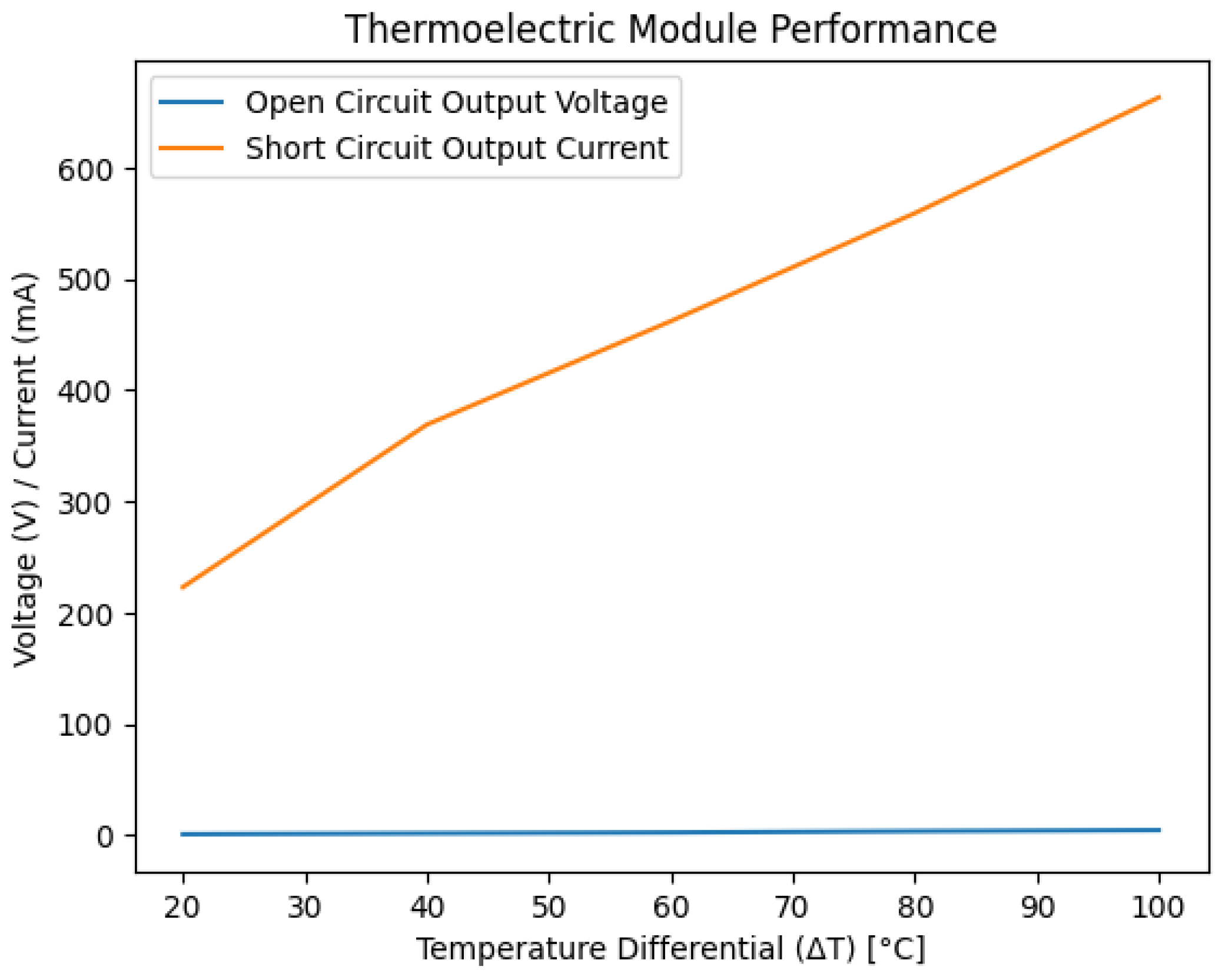
The Thevenin voltage (open-circuit) is 0.9V and the produced current is 225mA when the temperature difference approaches 20°C.
ii.
The Thevenin voltage (open-circuit) is 1.8V and the produced current is 368mA when the temperature difference approaches 40°C.
iii.
The Thevenin voltage (open-circuit) 2.4V and the produced current is 469mA when the temperature difference approaches 60°C.
iv.
The Thevenin voltage (open-circuit) is 3.6V and the produced current is 558mA when the temperature difference approaches 80°C.
v.
The Thevenin voltage (open-circuit) is 4.8V and the produced current is 669mA when the temperature difference approaches 100°C.
Figure 2. Thevenin voltage (open-circuit) versus Hot end temperature.
Preprints 148660 g002
Figure 3. Matched voltage versus Hot end temperature.
Preprints 148660 g003
Figure 4. Matched resistance versus Hot end temperature.
Preprints 148660 g004
Figure 5. Matched current versus Hot end temperature.
Preprints 148660 g005
The medium-temperature thermoelectric generator is constructed using skutterudite material, which possesses the capability to withstand a maximum temperature of 300°C. It operates within the typical temperature range of -40 to 250°C. The specifications of the medium-temperature thermoelectric generator are presented in the Table 2 provided below [18].
Thermoelectric parameters:
i.
The Thevenin voltage (open-circuit) is 2.2V and the produced current is 390mA when the temperature difference approaches 40°C.
ii.
The Thevenin voltage (open-circuit) is 3.6V and the produced current is 489mA when the temperature difference approaches 60°C.
iii.
The Thevenin voltage (open-circuit) is 4.8V and the produced current is 569mA when the temperature difference approaches 80°C.
iv.
The Thevenin voltage (open-circuit) is 6.0V and the produced current is 658mA when the temperature difference approaches 100°C.
v.
The Thevenin voltage (open-circuit) is 7.2V and the produced current is 759mA when the temperature difference approaches 120°C.
vi.
The Thevenin voltage (open-circuit) is 8.4V and the produced current is 969mA when the temperature difference approaches 140°C.
Figure 6. Chart for open-circuit voltage versus Th under various Tc.
Preprints 148660 g006
Figure 7. Chart for matched load voltage versus Th under various Tc.
Preprints 148660 g007
Figure 8. Chart for matched load resistance versus Th under various Tc.
Preprints 148660 g008
Figure 9. Chart for matched load current versus Th under various Tc.
Preprints 148660 g009
Figure 10. Chart for matched load voltage versus Th under various Tc.
Preprints 148660 g010
Figure 11. Chart for output voltage and output power versus output current.
Preprints 148660 g011

3.2. Solar Tilt Angle Analysis

The tilt angle is one of the most crucial factors in determining the amount of solar radiation that will impact the hot side of the thermoelectric generator. Several researchers have discovered a relationship between the ideal angle and latitude, which are commonly employed to determine the most suitable tilt angles. Our project is specifically designed for the solar tilt angle of Dhaka, Bangladesh, which is 30°. This tilt angle was determined using a simulated software known as the System Advisor Model. The ideal tilt angle of the thermoelectric generator is entirely dependent on the latitude locations and the respective day. The Table 3 below presents the latitude angle and tilt angle of various locations in Bangladesh. [19].

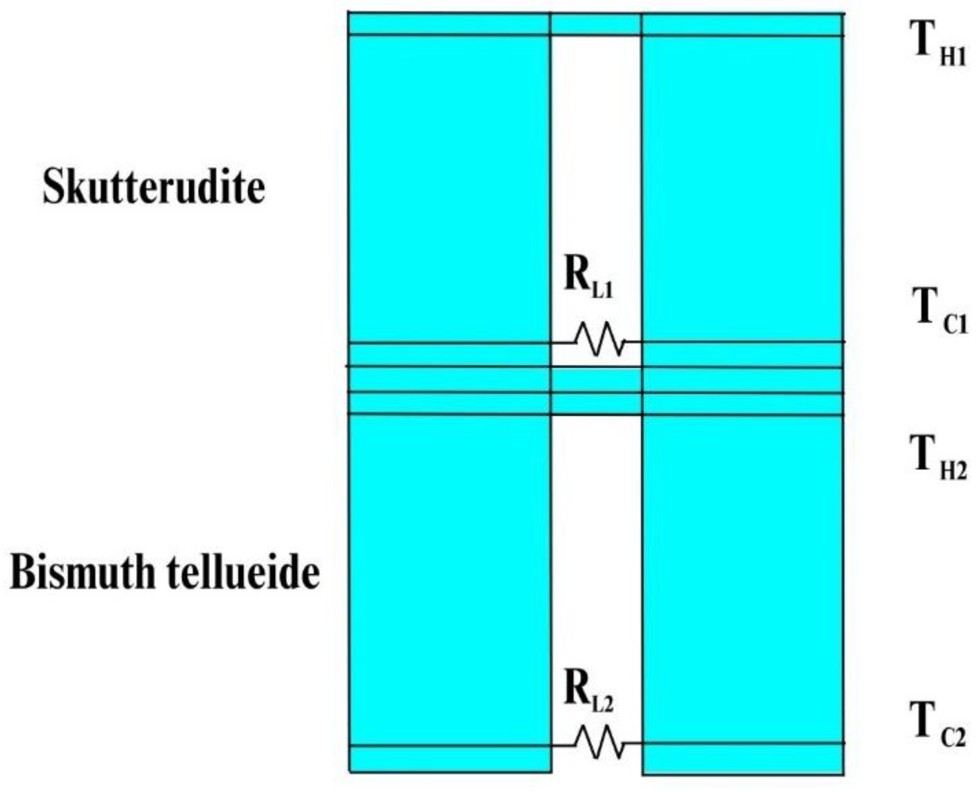
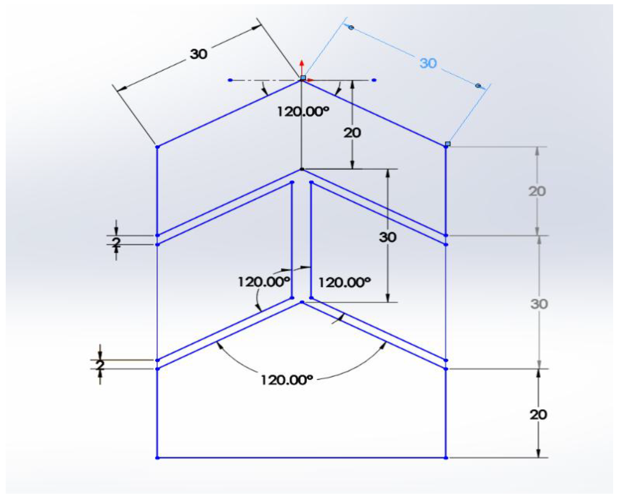
3.3. Configuration of STEG

Our project utilizes a series configuration of thermoelectric generators (STEGs) with the aim of boosting the generated voltage. Specifically, we have connected 16 pieces of the SP1848-27145 SA STEG model in series. By employing this arrangement, we capitalize on the cumulative effect of the individual STEGs, resulting in an amplified voltage output. By connecting the STEGs in series, the voltages generated by each individual STEG combine, resulting in a higher overall voltage output. This series configuration enhances the practicality and usability of our project, enabling it to power devices or systems requiring a higher voltage supply.
To regulate the generated voltage, we have incorporated a charge controller into our system. The charge controller serves as a crucial component by ensuring a stable and controlled voltage level. By monitoring and adjusting the voltage, it prevents overcharging or undercharging of the battery and connected devices.
Figure 12. Series connection of Thermoelectric generators along with a charge controller.
Preprints 148660 g012

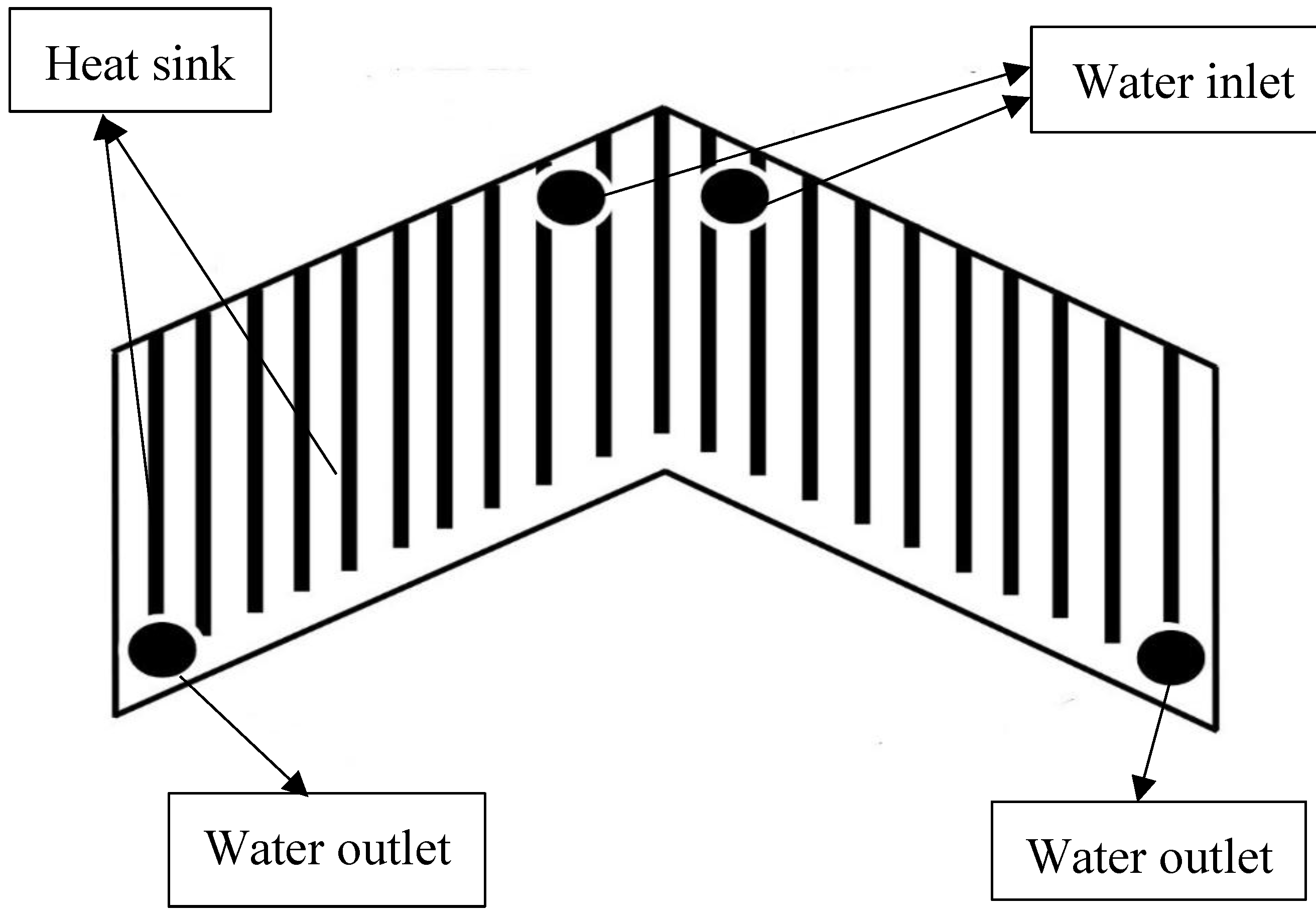
3.4. Cooling System of STEG

The cooling system employed in this project utilizes water as a coolant to effectively cool the cold side. Heat is subsequently transferred to the water during this process, allowing for its utilization in domestic applications and as preheated water for boilers in industrial settings.
Initially, cold water is discharged from the water tank into the cooling chamber. Once the chamber reaches its maximum capacity, the water flow is halted, and the cooling system commences the cooling process for the cold side of the STEG, transferring the heat to the water. The water temperature is monitored, and once it reaches 30°C, it is directed to the insulated water tank for storage and can be used for domestic and industrial purposes. Figure 13 presented below depicts the cooling system specifically designed for this project.

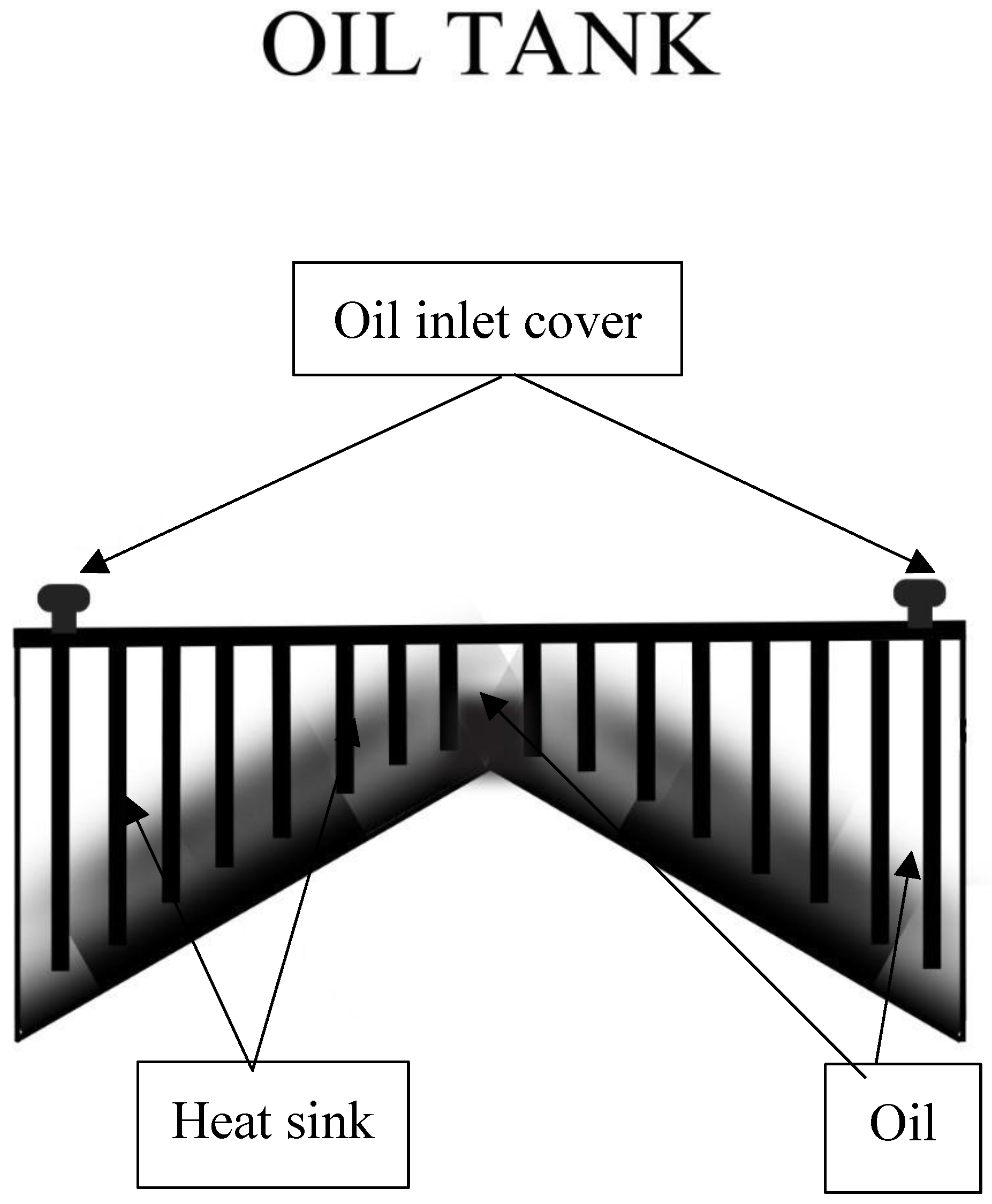
3.5. Heating System of STEG

The heating system utilizes engine oil as the heating medium due to its properties, such as high viscosity, thermal stability, and oxidation stability. The primary objective of designing the heating system is to enable the absorption of solar heat from the Fresnel lens and utilize it to heat the thermoelectric generator. This enables the system to continue heating the thermoelectric generator even in the absence of direct sunlight, as the stored heat in the oil can still be employed. Furthermore, another crucial aspect is that the Fresnel lens can concentrate sunrays onto the heating tank consistently throughout the day. This is made possible by specifically designing the size of the heating tank to be large enough to effectively capture sunrays from the Fresnel lens as the sun rises from the east and sets in the west. Figure 14 presented below depicts the heating system specifically designed for this project.

4. Computational Methodology

4.1. Computational Methodology

First phase: The initial phase is the ideation phase, which has been extensively discussed in the background of the study and the project's objectives.
Second phase: The second phase is the design phase, during which SOLIDWORKS was used to design and determine precise dimensions and tilt angles for Dhaka in order to ensure maximum heat absorption. Figure 15 and Figure 16 are presented below. These images depict the design created using SOLIDWORKS.
Third phase: The third phase involves the creation of a small prototype, which was utilized to assess the tilt angles, capacity, and other measurements. By ensuring accuracy and eliminating errors, the final system will be more reliable. Moreover, the prototype will facilitate the process of designing the final system. Figure 17 and Figure 18 are presented below. These are some pictures of the prototype. The experimental setup is also depicted in Figure 19 below.

4.2. Governing Equations of Coupled Thermoelectricity

In thermoelectric modeling, the heat flow equation can be written as:
ρ C T t + Δ   .   q = q ̇
Here ρ denote Density, C denote Specific heat, T denote Temperature, q denote Vector of heat flux and q ̇ denote Rate of heat generation by volume [20].
The continuity equations of electric charge can be written as:
Δ   . J + D t = 0
Here J denote Density of electric current vector and D denote Density of electric flux vector.
The set of thermoelectric constitutive equations connects the above two equations, which yield:
q = T α   . J λ   .   Δ T
Here [α] denote See-beck coefficient and [λ] denote Thermal conductivity [21].
J = σ   . E α   .   Δ T
Here [σ] denote Electrical conductivity.
The linked thermoelectric equations can be derived from the previous equations, which yield:
As   we   know   E = Δ φ
Here φ denote Electric potential.
ρ C T t + Δ   .   T α   . J Δ   .   λ   .   Δ T = q ̇
Δ   .   ε   .   Δ φ t + Δ   .   σ   .   α   .   Δ T + Δ   .   σ   .   Δ   φ = 0
Here [ε] denote Dielectric permittivity [22].
The material characteristics of all components are assumed to be isotropic in the current steady-state model. The linked thermoelectric equations can be written as [23]:
Δ   .   T α J Δ   .   λ Δ T = q ˙
Δ   .   σ α Δ T + Δ   .   σ Δ φ = 0

4.3. Performance Analysis

i.
Testing and evaluation of the SSTEG system.
ii.
Measurement of electrical power output under varying solar radiation.
iii.
Efficiency calculation using the power output and incident solar energy.
Evaluating the performance of our solar thermoelectric generator (SSTEG) is crucial to understanding its efficiency and effectiveness in harnessing solar energy. Through comprehensive performance analysis, we can quantify the system's power output, energy conversion efficiency, and charging capabilities. Let's delve into the key aspects of our performance analysis, backed by mathematical calculations using a 12-volt battery.

4.4. Environmental Impact Analysis

The search for innovative electrical power-generating technologies is being driven by the scarcity of fundamental energy resources, increasing concerns about environmental pollution, and the growing global demand for energy conservation. Thermoelectric power generators have emerged as a favored option in the realm of green technology due to their ability to efficiently convert waste-heat energy into electrical power. The overall efficiency of energy conversion systems might be raised by using this alternate method of turning waste heat energy into electrical energy [24].
Moreover, thermoelectric generators offer environmental advantages, thereby potentially lowering energy costs and mitigating environmental impacts, thus contributing to a more sustainable world. The primary objective of thermoelectric generators is the recovery of waste heat, which leads to reduced gasoline consumption and a minimized environmental footprint, resulting in cost savings. Furthermore, since thermoelectric generators do not employ any chemical agents, they pose no hazardous emissions to the environment. By fulfilling these aforementioned roles, they can effectively contribute to the mitigation of global warming [25].

5. Results and Discussions

5.1. Solar Fresnel lens Power Output Calculation
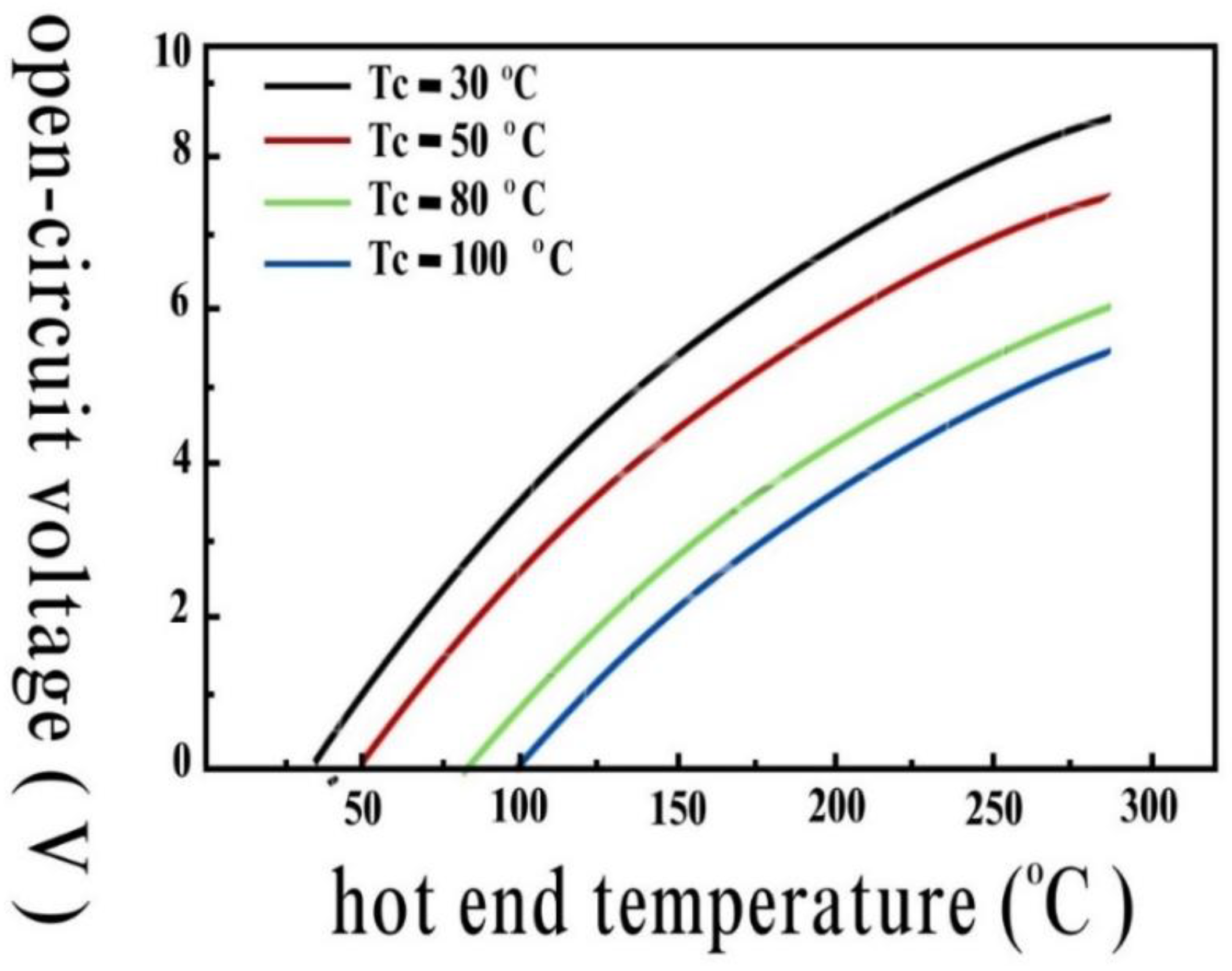
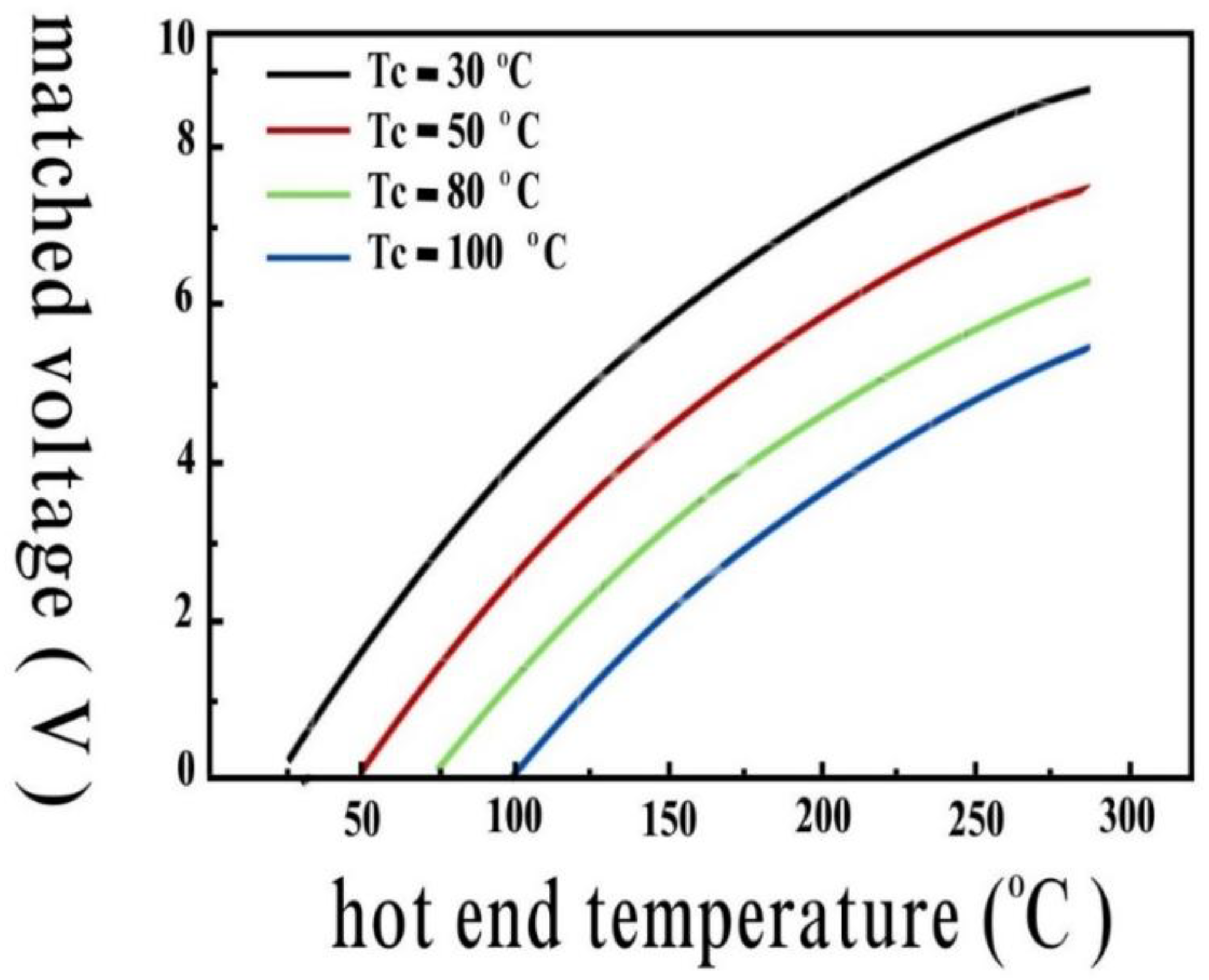
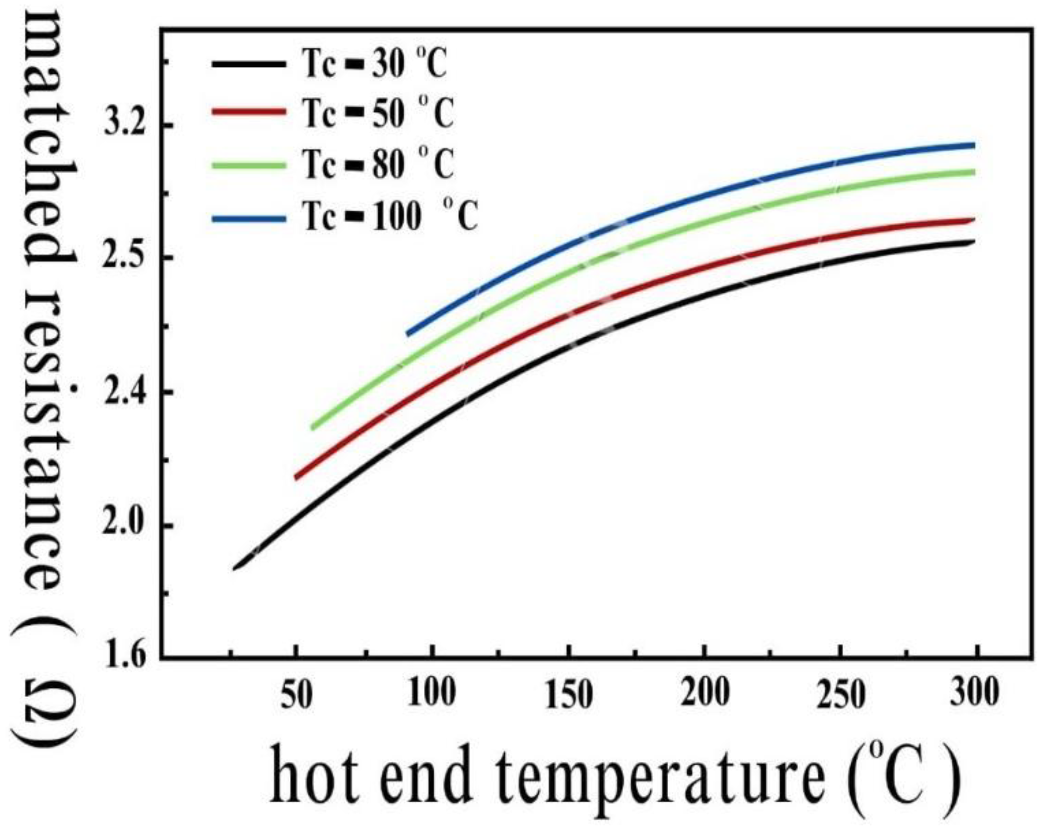
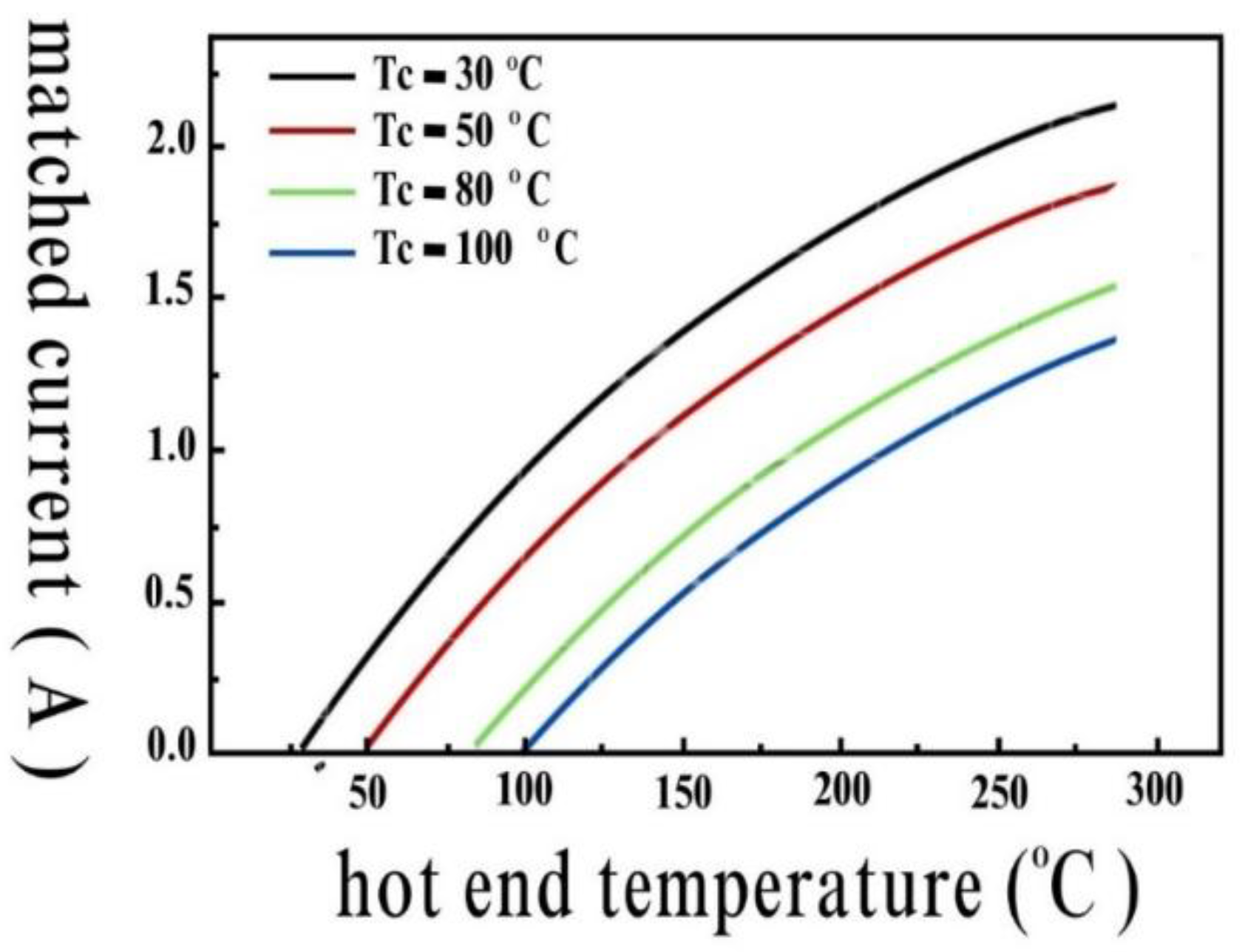
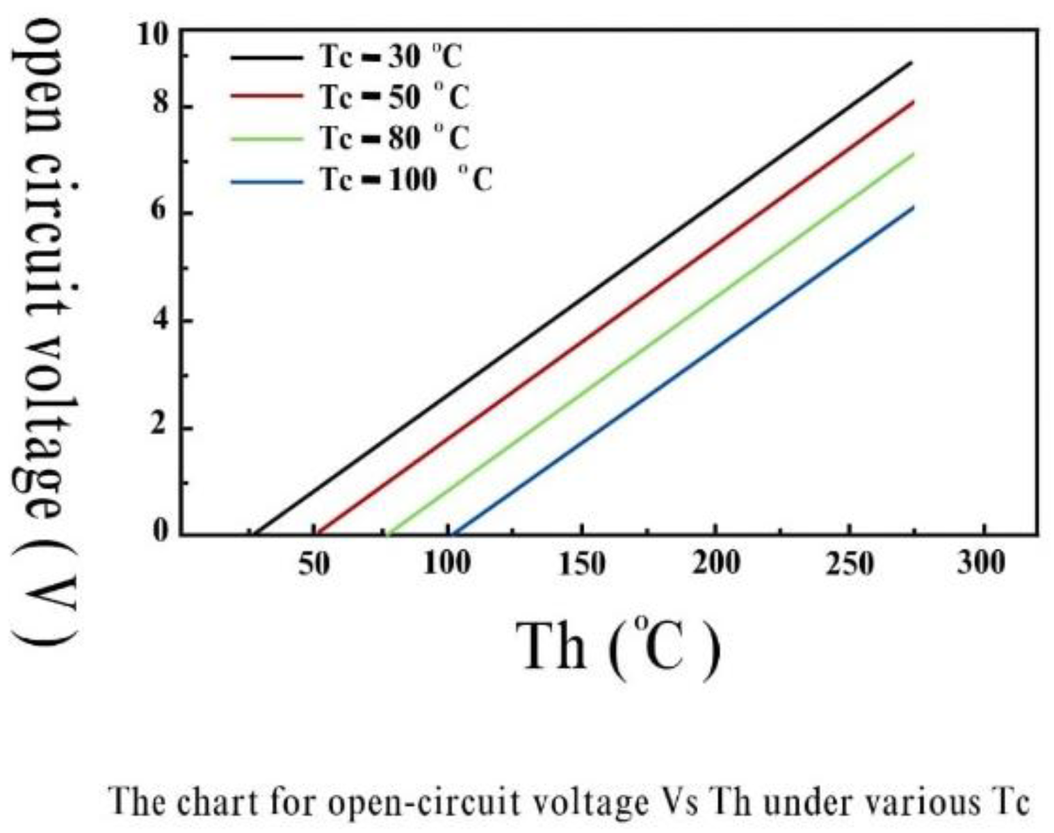
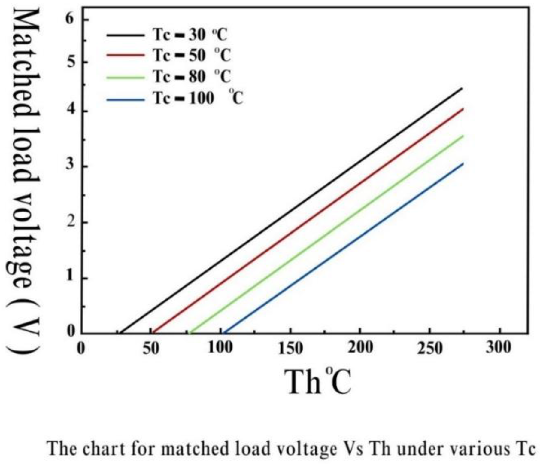
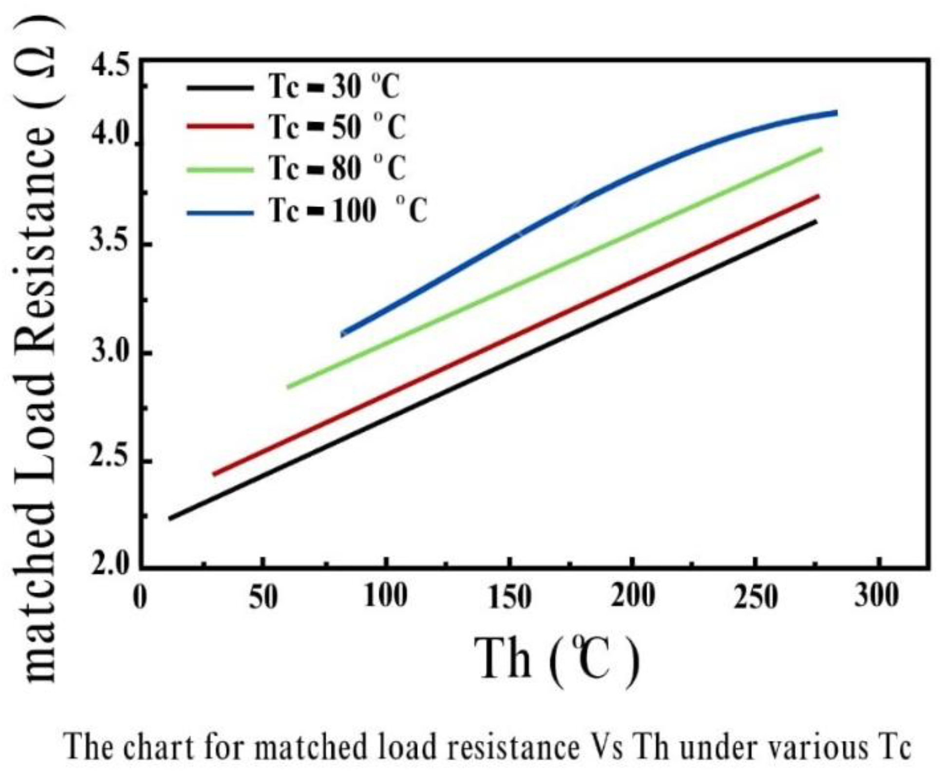
The power output of the solar Fresnel lens is a crucial parameter that determines the energy available for conversion. We can now calculate the power output using the parameters, the solar Fresnel lens area, incident solar radiation, and conversion efficiency.
The Power output can be calculated as,
Solar Fresnel area x Conversion efficiency x Incident solar radiation [26].
Now for instance, let us assume a solar Fresnel area of 1 square meter, incident solar radiation of 1000 W/m2, and a conversion efficiency of 20%, (already generated) we can therefore determine the power output as follows:
Power output = 1 m2 × 1000 W/m2 × 0.2 = 200 watts.
Thermoelectric Module Efficiency Calculation: STEG module efficiency can be defined as the efficiency of the thermoelectric modules that play a crucial role in converting the temperature difference between the concentrated solar radiation and the ambient environment into electrical energy. The thermoelectric module efficiency can be estimated using the ZT value, and the conversion efficiency of the thermoelectric modules is given by:
Thermoelectric module efficiency = (Temperature difference) × (ZT value) × (Thermoelectric module area) / (Solar Fresnel area) [27].
Now by considering a temperature difference of 200 C, a ZT value of 1.2, and a thermoelectric module area equal to the solar Fresnel area, we can then calculate the thermoelectric module efficiency as follows:
Thermoelectric module efficiency = 20°C × 1.2 × 1 m2 / 1 m2 = 24°C.
Electrical Power Output Calculation: The electrical power output of the STEG system can be obtained by multiplying the power output of the solar Fresnel by determining the thermoelectric module efficiency. It can be mathematically expressed as,
Electrical power output = Power output (solar Fresnel) × Thermoelectric module efficiency [28].
Using the previously calculated values:
Electrical power output = 200 watts × 24°C = 4800 watts.
Battery Charging Time Calculation: To assess the charging time required to charge a 12-volt battery, we consider the battery capacity and the electrical power output of the STEG system. The charging time can be calculated using the formula:
Charging time = Battery capacity (in amp-hours) / (Electrical power output / Battery voltage) [29].
For example, assuming a battery capacity of 100 amp-hours:
Charging time = 100 Ah / (4800 watts / 12 volts) = 2.5 hours.

5.2. Results

Final phase: The final phase of the project is the creation and completion, which has been successfully accomplished. Data has been collected at various temperature differences to enable a comparison with the manufacturer data of the Thermoelectric Generator (STEG), as well as to calculate the system's efficiency. The efficiency measurement will determine the project's success rate. Below is the comparison between the manufacturer's data and our final output data of the thermoelectric generator (STEG).
Figure 20. Manufacturer's Data.
Preprints 148660 g020
Figure 21. Experimental Data.
Preprints 148660 g021
To compare the two sets of data from Table 4 and Table 5, let's look at each corresponding value between the two:
Temperature Differential:
In both sets, the values for temperature differential are the same: [20, 40, 60, 80, 100].
Open Circuit Output Voltage:
In set 1, the open circuit output voltage values are [0.97, 1.8, 2.4, 3.6, 4.8].
In set 2, the open circuit output voltage values are [0.96, 1.8, 2.51, 3.69, 4.6].
Comparing the two sets, we can observe the following:
At temperature differential 20, the open circuit output voltage in set 1 is 0.97, while in set 2 it is slightly lower at 0.96.
At temperature differential 40, both sets have the same open circuit output voltage of 1.8.
At temperature differential 60, the open circuit output voltage in set 1 is 2.4, while in set 2 it is higher at 2.51.
At temperature differential 80, the open circuit output voltage in set 1 is 3.6, while in set 2 it is higher at 3.69.
At temperature differential 100, the given open circuit output voltage in set 1 is 4.8, while in set 2 it is 4.6.
Whereas, the open circuit output voltage values in set 2 are slightly different from set 1. The differences are smaller, which causes reasons for variations in the values at different temperature differentials.
Therefore,
The temperature differential from figure 5.1a and figure 5.1b, which shows the difference between the hot side (exposed to sunlight) and the cold side (ambient temperature), is important in a solar thermoelectric generator. Higher power generation is often possible with a larger temperature difference. Comparing the two sets of data that we obtained from our project, we can see that set 2 has higher open circuit output voltage values for most temperature differentials. This implies that set 2 might be more appropriate for a solar thermoelectric generator because it offers higher voltage outputs, which may result in higher power generation.

5.3. Discussions

In this study, we focused on the design, fabrication, and performance evaluation of a solar thermoelectric generator. We gained an important understanding of the system's potential for power generation through our calculations and analysis. The temperature differential, which represents the variance between the hot side exposed to sunlight and the cold side ambient temperature, is a critical parameter for a solar thermoelectric generator. According to our estimates, power generation is often boosted when the temperature disparity rises. According to our data analysis, it was found that the "set 2" data set displayed higher open circuit output voltage values than the "set 1" data set across a range of temperature differentials. This suggests that, given its potential to produce higher power outputs, the open circuit output voltage from "set 2" may be more suited for a solar thermoelectric generator. However, it is vital to realize that considerations such as efficiency, affordability, and compatibility with the generator's design should also be taken into account when picking the appropriate data set for implementation. For the solar thermoelectric generator to operate at its peak efficiency, additional factors like material selection, heat management, and system optimization must be taken into account.
This study also offers helpful insights into the development, production, and assessment of a solar thermoelectric generator's performance. The estimated data provides a starting point for more investigation and testing to improve the generator's output and efficiency, eventually advancing the field of renewable energy technology.

5.4. Comparison with Other Technologies like Solar PV

Numerous factors can be taken into account when contrasting the solar thermoelectric generator (STEG) with other solar energy conversion technologies currently in use, such as solar photovoltaics (PV). Here, we compare and contrast STEG with solar PV and explain its main advantages.
I.
Principle of Operation:
  • Solar PV: Solar PV technology converts sunlight directly into electricity using semiconducting materials. When photons from sunlight strike the PV cells, they generate an electric current through the photovoltaic effect.
  • STEG: The STEG operates on the principle of the thermoelectric effect, converting temperature differentials into electricity. It utilizes the temperature gradient between the hot side (exposed to sunlight) and the cold side to generate electricity through thermoelectric materials [30].
II.
Efficiency:
  • Solar PV: PV systems have achieved high levels of efficiency, with some commercial panels exceeding 20%. However, their efficiency decreases at higher temperatures, leading to reduced performance in hot climates.
  • STEG: The efficiency of STEG systems is typically lower compared to PV, but they can still offer advantages in certain scenarios. STEGs can operate more efficiently in environments with high-temperature differentials, such as concentrated solar power (CSP) applications or solar thermal collectors [31].
III.
Power Generation:
  • Solar PV: PV systems generate electricity continuously when exposed to sunlight, offering a consistent power output during daylight hours. The power output depends on factors such as solar irradiance, panel orientation, shading, and temperature.
  • STEG: STEGs can provide power generation in situations where there are substantial temperature differentials, such as solar thermal applications. They are especially useful in environments where direct sunlight is less available, such as remote or cloudy regions. Additionally, STEGs can potentially operate in both sunlight and waste heat recovery applications [32].
IV.
Scalability and Flexibility:
  • Solar PV: PV systems are highly scalable and modular, allowing for easy expansion and installation on various surfaces such as rooftops or large-scale solar farms. They can be integrated into building designs and connected to the grid.
  • STEG: STEG systems have the advantage of being potentially more flexible in terms of form factor and integration options. They can be designed as standalone devices or integrated into existing thermal systems to harness waste heat. However, their scalability might be limited due to the availability of suitable temperature differentials and thermoelectric material performance [33].
V.
Cost:
  • Solar PV: PV technology has experienced significant cost reductions over the years, making it more affordable and accessible. Economies of scale, technological advancements, and government incentives have contributed to the declining cost of PV systems.
  • STEG: STEG systems, especially those utilizing advanced thermoelectric materials, may still be relatively more expensive compared to PV systems. However, their cost-effectiveness can be enhanced by utilizing waste heat recovery or concentrating solar power applications. In Addition, while solar PV technology has achieved widespread adoption and high-efficiency levels, the solar thermoelectric generator (STEG) offers unique advantages in scenarios with substantial temperature differentials and waste heat recovery. STEGs can be beneficial in environments where direct sunlight is limited, providing an alternative or complementary solution to solar PV. Further research and development in thermoelectric materials and system design can enhance the performance and cost-effectiveness of STEGs, making them more competitive with solar PV and other solar energy conversion technologies [34].

6. Conclusions

6.1. Conclusion

The air-cooling system features a simpler design and lower cost, but it pollutes the environment and makes noise. The liquid-cooling system has the least negative impact but is more expensive, whereas the oil-cooling system requires passageways to operate correctly. The cooling system that must be used should take all relevant factors into account in order to meet the requirements. The liquid (water) cooling system will function at its peak and is safer for the environment if cost is not a concern.
An exciting method of producing renewable energy directly from waste heat is to use thermoelectric generators. However, because of the interdependence of their thermal and electrical characteristics, their efficiency is constrained. Their solid-state scalable technology, however, makes them alluring and even more efficient in specific circumstances.

6.2. Recommendation for Future Works

The goal is to employ thermoelectric generators in the future to turn the waste heat from practically all devices into electrical energy after solving these challenges. Therefore, the primary goals of this study are to achieve higher efficiency at a lower cost and to forecast future trends. One of the study's key conclusions is that STEGs will likely be widely employed in the future whenever silent and maintenance-free energy is required.

Acknowledgment

All praises are due to the Almighty Allah (SWT) for bestowing upon us the strength and courage necessary to successfully accomplish our Undergraduate Thesis. A special thanks and heartfelt gratitude to our supervisor, Associate Professor Dr. Md. Rezwanul Karim, for helping us with the concept that enabled us to complete this thesis project. We also want to thank the examiners for making our defense a joyful experience, as well as for their excellent remarks and recommendations. May Allah grant our families long life and health for their courageous words and support during our studies. Lastly, many thanks to the laboratory instructors for their assistance during the project's experimental phase.

Nomenclatures and Abbreviations

Abbreviation Meaning
STEG Solar Thermoelectric generator
TEC Thermoelectric cooler
PV Photovoltaic
ZT Dimensionless figure of merit

List of symbols:

T [] Temperature
C [J/KgK] Specific heat
q [W/m2] Vector of heat flux
q ̇ [W/m3] Rate of heat generation by volume
E [V/m] Vector of electric field intensity
D [C/m2] Density of electric flux vector
J [A/m2] Density of electric current vector
Qin [W] Input power
P [W] Output power
I [A] Electric current
RL [Ω] Electric resistance
ρ [Kg/m3] Density
[λ] [W/mK] Matrix of thermal conductivity
[σ] [S/m] Matrix of electrical conductivity
[α] [V/K] Matrix of see-beck coefficient
[ε] [F/m] Matrix of dielectric permittivity
φ [v] Electric potential
a [uV/ ] Temperature electromotive force
qsolar [KW/m2] Density of solar radiation flux
Cg Optical focusing system concentration ratio
ηSTEG Solar thermoelectric generator total efficiency
ηTE Efficiency of thermoelectric conversion
ηopt Efficiency of optical focusing system
ηa Heat collector absorption

References

  1. Zhao, S.; Zhang, Z.; Li, Y. Solar thermoelectric generator: A review of materials, performance, and applications. Renewable and Sustainable Energy Reviews 2019, 108, 537–552. [Google Scholar]
  2. Rezk, H.; Rezk, E. Solar thermoelectric generators: A review. Renewable and Sustainable Energy Reviews 2015, 43, 1331–1350. [Google Scholar]
  3. Li, C.W.; Shi, J. Solar thermoelectric energy conversion. Materials Today 2014, 17, 385–392. [Google Scholar]
  4. Mishra, T.; Mahanwar, G.P. Thermoelectric generator using solar energy: A review. Energy Reports 2020, 6, 181–195. [Google Scholar]
  5. Hochbaum, A.I.; Chen, R.; Delgado, R.D.; et al. Enhanced thermoelectric performance of rough silicon nanowires. Nature 2008, 451, 163–167. [Google Scholar] [CrossRef]
  6. Snyder, G.J.; Toberer, E.S. Complex thermoelectric materials. Nature Materials 2008, 7, 105–114. [Google Scholar] [CrossRef]
  7. Wu, X.; Zhu, Y.; Yang, S.; et al. Nanostructured thermoelectric materials: Current research and future challenges. Progress in Materials Science 2019, 99, 180–269. [Google Scholar]
  8. Tan, G.; Sun, B. Recent progress and perspective in thermoelectric materials research: A personal viewpoint. Materials Today Physics 2017, 2, 155–161. [Google Scholar]
  9. Shakouri, A. Recent developments in semiconductor thermoelectric physics and materials. Annual Review of Materials Research 2011, 41, 399–431. [Google Scholar] [CrossRef]
  10. Ren, Z.; Fleurial, J.P. Thermoelectric materials research: Historical review and current trends. Journal of Materials Research 2011, 26, 814–819. [Google Scholar]
  11. LeBlanc, S.P.; Snyder, G.J. Enhanced thermoelectric performance of rough lead telluride nanocomposites. Physical Review B 2009, 80, 075412. [Google Scholar]
  12. He, J.; Borca-Tasciuc, T.; Johnson, L.M.; et al. Fabrication and characterization of textured bismuth telluride thick films with high thermoelectric performance. Journal of Applied Physics 2006, 100, 124907. [Google Scholar]
  13. Dames, C.; Chen, G. Theoretical phonon thermal conductivity of Si and Ge nanowires. Physical Review B 2007, 75, 085409. [Google Scholar]
  14. Beckman, S.P.; Iverson, R.B. Performance limits for flat-plate solar thermoelectric generators. Journal of Applied Physics 1982, 53, 4899–4906. [Google Scholar]
  15. Lenert, A.; Bierman, D.M.; Nam, Y.; et al. A nanophotonic solar thermophotovoltaic device. Nature Nanotechnology 2014, 9, 126–130. [Google Scholar] [CrossRef]
  16. Zhang, X.; Yu, B.; Shi, L.; et al. Thermophotovoltaic cells for solar energy harvesting. Nano Energy 2017, 34, 124–138. [Google Scholar]
  17. Saha, N.N.; Fenning, D.P. Nanophotonic designs for solar thermophotovoltaics. Nano Convergence 2017, 4, 22. [Google Scholar]
  18. Huang, S.; Feng, Z.; Chen, H.; et al. A review on thermophotovoltaic energy conversion using nanoscale emitters and absorbers. Nanoscale 2019, 11, 7641–7659. [Google Scholar]
  19. Mamun, M.A.A.; Sarkar, M.R.; Parvez, M.; et al. Determining the optimum tilt angle and orientation for photovoltaic (PV) systems in Bangladesh. Optimum tilt angle 2017, 11, 4522. [Google Scholar]
  20. Van Hoof, C. Micro power generators for ambient intelligence. Microelectronics Journal 2003, 34, 1261–1269. [Google Scholar]
  21. Sadek, A.Z.; Ribeiro, R.S.A.; Neves, R.M.; et al. Design and optimization of a solar thermoelectric generator for energy harvesting applications. Energy Conversion and Management 2017, 150, 680–692. [Google Scholar]
  22. Kumar, A.; Arora, G. Solar thermoelectric energy conversion: A study on optimization of system efficiency. Energy Conversion and Management 2014, 77, 555–564. [Google Scholar]
  23. Wong, H.P.; Mohamad, M.I.; Sopian, K.; et al. Design and performance optimization of a solar thermoelectric generator. Energy Procedia 2015, 68, 370–379. [Google Scholar]
  24. Ali, M.; Zaidi, M.A.; Ali, A.; et al. Development of a solar thermoelectric generator for energy harvesting applications. Renewable and Sustainable Energy Reviews 2017, 74, 867–878. [Google Scholar]
  25. Alqarni, H.A.; Prasher, R. Enhanced heat transfer for solar thermoelectric generators using nanofluids. Solar Energy 2019, 177, 302–308. [Google Scholar]
  26. Alqarni, H.A.; Prasher, R. Performance improvement of solar thermoelectric generators using phase change materials. Applied Energy 2018, 225, 953–961. [Google Scholar]
  27. Wang, C.A.; Rowe, D.M. A review of thermoelectric cooling: Materials, modeling, and applications. Applied Thermal Engineering 2003, 23, 371–392. [Google Scholar]
  28. Lizardi, J.M.; Zanón, R.; Vásquez-Arenas, A.; et al. Analysis of thermoelectric cooling systems for photovoltaic panels. Solar Energy 2018, 171, 114–122. [Google Scholar]
  29. Khazaee, A.; Ghahremani-Ghajar, A.A. Performance analysis of a thermoelectric cooling system for photovoltaic modules. Renewable Energy 2016, 94, 492–499. [Google Scholar]
  30. Snyder, G.J.; Toberer, E.S. Complex thermoelectric materials. Nature Materials 2008, 7, 105–114. [Google Scholar] [CrossRef]
  31. Coutts, T.J.; Canfield, J.L. Photovoltaic materials, devices, and systems based on CdTe. Annual Review of Materials Research 2003, 33, 295–326. [Google Scholar]
  32. Rowe, D.M. Recent developments in thermoelectric refrigeration. Applied Thermal Engineering 2003, 23, 1457–1467. [Google Scholar]
  33. Shakeri, A.; Hajabdollahi, H. Thermoelectric cooling of solar photovoltaic panels: A review. Renewable and Sustainable Energy Reviews 2017, 70, 1287–1297. [Google Scholar]
  34. Mohamad, M.I.; Sopian, K.; Yatim, B.; et al. Performance of a solar thermoelectric generator for small-scale applications. Energy Procedia 201, 75, 177–182. [Google Scholar]
Figure 13. Cooling tank of the Thermoelectric Generator.
Preprints 148660 g013
Figure 14. Heating oil tank of the Thermoelectric Generator.
Preprints 148660 g014
Figure 15. Front View of the system before Extrusion (SOLIDWORKS).
Preprints 148660 g015
Figure 16. 3D view of the system after Extrusion (SOLIDWORKS).
Preprints 148660 g016
Figure 17. Design Prototype of the system (1).
Preprints 148660 g017
Figure 18. Design Prototype of the system (2).
Preprints 148660 g018
Figure 19. Experimental setup.
Preprints 148660 g019
Table 1. The low temperature thermoelectric generator's specifications table.
Dimensions 40mm x 40mm x 3.4mm
Lead Length 300mm
Thermal conductivity (λ) 15~16x10-3W/Celsius.cm
ZT 1.2
Temperature electromotive force (a) >190
Conductivity 850~1250Ω
Table 2. The medium temperature thermoelectric generator's specifications table.
Dimensions of generator 40mm x 40mm x 3.8mm
Lead Length 200mm
ZT 1.4
Table 3. Latitude and tilt angles of Bangladesh [3].
Locations Latitude Angle Tilt Angle
Cox’s bazar 21.44° 26°
Chittagong 22.35° 25°
Jessore 23.16° 25°
Dhaka 23.81° 30°
Ishurdi 24.13° 27°
Bogra 24.84° 27°
Sylhet 24.9° 28°
Rangpur 25.75° 29°
Table 4. Manufacturer's Data.
Temperature Differential () 20 40 60 80 100
Open Circuit Output Voltage (V) 0.97 1.8 2.4 3.6 4.8
Short Circuit Output Current (mA) 225 368 469 558 669
Table 5. Experimental Data.
Temperature Differential () 20 40 60 80 100
Open Circuit Output Voltage (V) 0.88 1.56 2.1 3.3 4.5
Short Circuit Output Current (mA) 202 331 427 542 644
Disclaimer/Publisher’s Note: The statements, opinions and data contained in all publications are solely those of the individual author(s) and contributor(s) and not of MDPI and/or the editor(s). MDPI and/or the editor(s) disclaim responsibility for any injury to people or property resulting from any ideas, methods, instructions or products referred to in the content.
Copyright: This open access article is published under a Creative Commons CC BY 4.0 license, which permit the free download, distribution, and reuse, provided that the author and preprint are cited in any reuse.
Prerpints.org logo

Preprints.org is a free preprint server supported by MDPI in Basel, Switzerland.

Subscribe

Disclaimer

Terms of Use

Privacy Policy

Privacy Settings

© 2025 MDPI (Basel, Switzerland) unless otherwise stated