1. Introduction
Implantology has taken a big step forward recently, being one of the solutions preferred by both dentists and patients. Studies related to the methods and materials used for dental implants have been developed. This work presents an original approach to the study of a dental implant, required by a vertical axial compression force. The study was done by applying the Transfer-Matrix Method (TMM), using the facilities offered by the mathematical formalism given by the functions and operators of Dirac and Heaviside. The originality consists in assimilating the dental implant with a straight bar, articulated at both ends. TMM is very easy to program and gives results very quickly for problems of optimizing the form of some pieces must be solved, in occurrence, of dental implants. For dental implants, the materials used to make them are very important. There are many materials used for dental implants, but the most important are titanium and its alloys, because it has good durability, it is resistant to corrosion and its most important characteristic is biocompatibility and the mechanical properties (like the bone tissue) as a good hardness and a good corrosion resistance. Risks of buckling are higher for straight bars compressed with an axial force, that is very important to know the critical buckling force.
The research on dental implants is very wide, as can be seen from the numerous publications in the field, of which, in the following, are presented some of them, both from the technical and from the medical field.
The bases for the calculus of different structures by TMM are presented in [
1]. The classical calculus of resistance of materials is given in [
2] and [
3]. TMM for calculus of long cylinder tube with industrial applications is shown in [
4] and [
5] presents an approach by TMM for mandible body bone calculus. [
6] gives the calculus of a monobloc dental bridge with two poles and two missing teeth as a beam by TMM. About the calculus through the TMM of a beam with intermediate support with applications in dental restorations is given in [
7]. Practical notions for dental preparation for fixed single-dental prostheses are given in [
8]. Figures of graph partitioning by counting, sequence and layer matrices are presented in [
9]. A high order finite strip TMM for buckling analysis of single-branched cross-section thin-walled members can be shown in [
10]. Current knowledge and open questions about osseointegration of titanium, titanium alloy and zirconia dental implants are presented in [
11]. A histomorphometry study in miniature pigs about the influence of surface characteristics on bone integration of titanium implants is given in [
12] and in [
13] are presented recent development in beta titanium alloys for biomedical applications. The factors of influence and evaluation for the role of primary stability for successful osseointegration of dental implants can be shown in [
14]. Biomechanical analysis of alveolar bone stress around implants with different thread designs and pitches in the mandibular molar area is given in [
15]. Buckling of piles in layered soils by TMM is presented in [
16] and in [
17] can be shown titanium-based biomaterials for preventing stress shielding between implant devices and bone. Influence of implant taper on the primary and secondary stability of osseous-integrated titanium implants is presented in [
18]. Mechanical reliability, fatigue strength and survival analysis of new polycrystalline translucent zirconia ceramics for monolithic restorations are given in [
19]. A literature review about the influence of thread geometry on implant osseointegration under immediate loading is presented in [
20]. Precise TMM for elastic-buckling analysis of compression bar can be shown in [
21]. Study about the bending beam on elastic environment by TMM is presented in [
22] and [
23] gives a study about buckling bio-composite sandwich bars. An approach for buckling calculus of dental implant as a bar on elastic environment by TMM can be found in [
24] and [
25] presents a buckling calculus of straight bars on elastic environment by TMM for dental implants. A biomechanical and histological analysis effect of implant thread geometry on secondary stability, bone density and bone-to-implant contact can be found in [
26]. A review of the surface modifications of titanium alloys for biomedical applications can be shown in [
27]. Relevant aspects in the surface properties in titanium dental implants for the cellular viability are given in [
28]. Fabrication and properties of functionally graded dental implant can be found in [
29]. A review about the revitalizing concepts with technology tapered implants in dentistry is presented in [
30]. Production and characterization of a bone, like porous Ti/Ti-hydroxyapatite functionally graded material are given in [
31].
This work will serve to future research about dental implants. The TMM is very easy to program, for theoretical tests used to optimize the implants forms and after, in the future, to validate theoretical results with Finite Element Method (FEM) and with experimental tests in laboratory and in situ.
2. Materials and Methods
2.1. Materials
As is known, that a dental implant consists of a dental abutment and a crown that replaces the missing tooth. The abutment has the lower end in the bone, and the upper end is the base for the dental crown, being a screw that screws into the bone, replacing the dental root, being a connector between the bone and the dental crown.Several types of materials can be used for dental abutment. The most frequently used materials are titanium and zirconium. The most important is titanium, because it has good durability, is resistant to corrosion and its most important characteristic is the biocompatibility, being used especially in areas with high masticatory forces, in the back of the mouth. Zirconium is highly appreciated from an aesthetic point of view and has a good integration with the gingival tissues, being used especially in areas where the aesthetic aspect is important, i.e. in the front part of the mouth. Gold and its alloys are less preferred today, due to the high cost and inappropriate color, even if it is biocompatible and easy to process. Poly-ether-ether-ketone (PEEK) is biocompatible and has good elasticity, being an advanced plastic material, used in special situations or for temporary dental works. In order to obtain an efficient and versatile solution at the same time, the hybrid version can be used. There is also the possibility of making a hybrid implant, combining the advantageous characteristics of two or more materials, in order to obtain the optimal option both from an aesthetic point of view, but especially from a functional point of view. In this paper, a straight implant is studied, being assimilated with a double articulated bar subjected to buckling by an axial compression forces.
2.2. Methods
2.2.1. The Transfer-Matrix Method for a doubly articulated straight bar on the rigid environment
The basis of TMM is presented in [
1]. In order to be able to study a double-jointed bar subjected to buckling on an elastic environment, the double-jointed bar subjected to buckling on a rigid environment will first be studied.
2.2.1.1. The differential equation of the deformed average fiber for a doubly articulated right bar subjected to buckling on the rigid environment
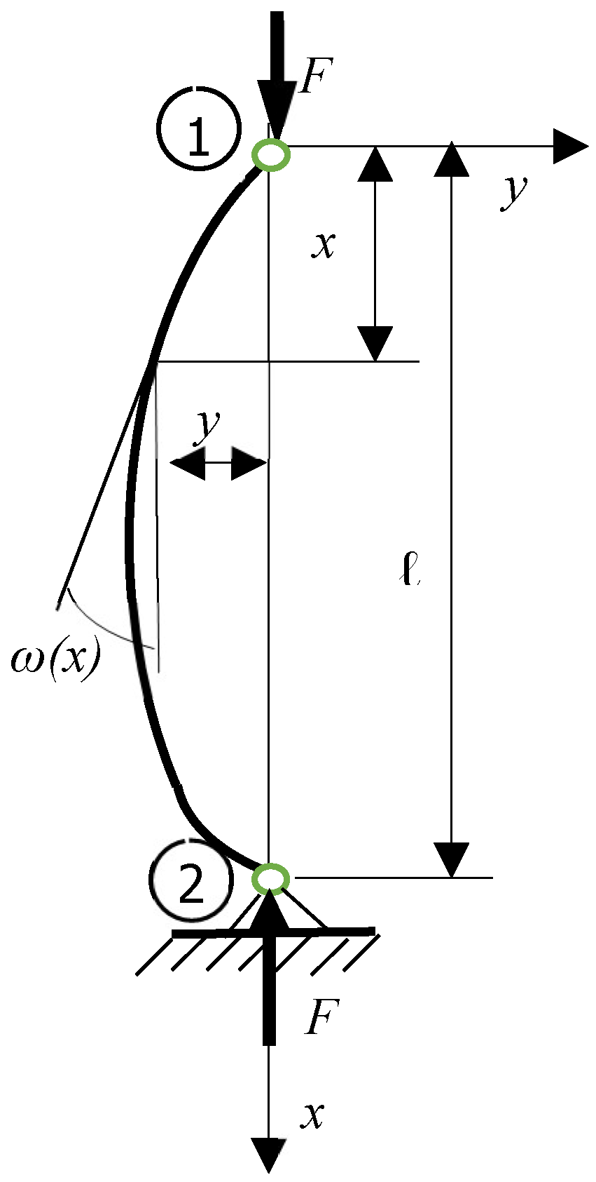
Several working hypotheses are used to deduce the differential equation of the deformed average fiber for a doubly articulated right bar subjected to buckling, a bar as in
Figure 1. The working hypotheses are:
- -
the bar is with length l;
- -
for over entire length, the bar has constant moment of inertia;
- -
a force
F acts in direction of axis
x of the bar on extremities, which tend to compress the bar, as in
Figure 1.;
- -
in a section x, the arrow is noted with y;
- -
in a section x, the rotation is noted with ω;
- -
the curvature at the deformed elastic line is relatively small.
The differential equation of the deformed average fiber, after [
2] and [
3], is as (1):
M(x) is the total bending moment corresponding at the current section
x, with expression (2):
With expression (2), the differential equation (1) becomes as (3):
Deriving (3) twice, it is successively obtained (4):
and (5):
or, (6):
(6) is a a homogeneous linear differential equation with constant coefficients. It is noted
with (7):
With (7), the differential equation (6) becomes as (8):
having the characteristic equation (9):
The general solution of the characteristic equation (9) is of the form given by (10):
The relation (10) is derived three times and expressions (11), (12) and (13) are successively obtained:
For
x = 0, in the origin, the expressions (10), (11), (12) and (13) becomes (14), (15), (16) and (17):
The four integration constants
Ai, i=1,4 are calculated and the expressions (18), (19), (20) and (21) are obtained:
With the four integration constants Ai, i=1,4:
- -
expression (10) becomes as (20):
- -
expression (11) becomes as (22):
- -
expression (12) becomes as (24):
- -
expression (13) becomes as (26):
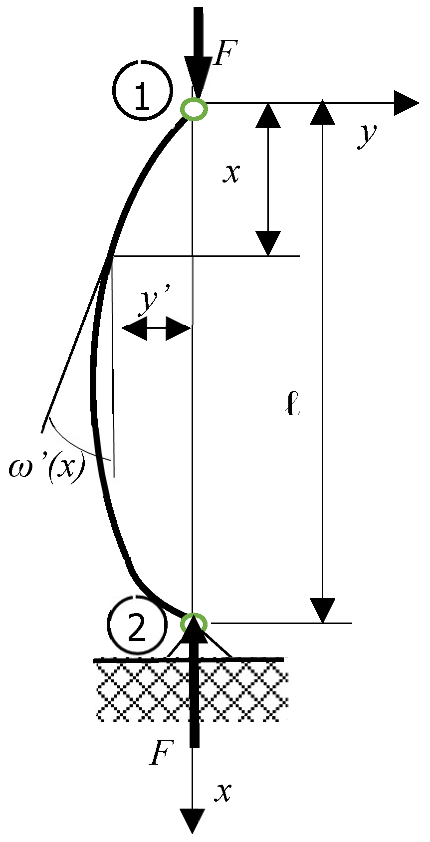
2.2.1.2. The Transfer-Matrix for a doubly articulated buckling bar (Figure 2.)
It can be defined the state vectors and the transfer-matrix of a straight bar, loaded with a concentrated force on the ends, as in
Figure 2.
It can be written in section x, the deformation y.
The state vector for a section x
It can be defined the state vector for a section
x of a bar, a column-vector with 4 elements as (28):
when:
- -
{V(x)} = {V}x is the state vector corresponding at the section x;
- -
y(x) is the arrow corresponding at the section x;
- -
ω(x) is the rotation corresponding at the section x;
- -
M(x) is the bending moment corresponding at the section x;
- -
T(x) is the cutting force corresponding at the section x;
For the first section, the left section, the origin, for
x = 0, the state vector is as (29):
At the last section on the right end, for
x = l, it can be written the state vector as (30):
The connection between the origin section for
x = 0 and a certain section
x, can be made through the matrix relation (31):
with notations:
- -
{V}x is the state vector corresponding to the section x;
- -
[T]x is the Transfer-Matrix between the origin and the section x;
- -
{V}0 is the state vector corresponding to the origin section;
- -
[Te]x·{Ve}x is a term wich corresponds to the exterior loads acting to the section x.
For a section x, expressions (21), (23), (25) and (27) can be written as (32):
or in the form of a matrix relation like (33):
For the last section, for
x = l, it can be written the matrix relation (33) as (34):
Now, it is possible to put the conditions at the two ends, for the doubly articulated right bar, as (35):
2.2.2. The Transfer-Matrix Method for a straight double-articulated buckling bar on elastic environment
It is attempted to deduct the Transfer-Matrix for a bar that is on a perfectly uniform and homogeneous elastic medium, knowing the function that is the coefficient of elasticity of the elastic medium
k (x), (
Figure 3.).
2.2.2.1. The differential equation of the deformed average fiber for a doubly articulated right bar subjected to buckling on the elastic environment
The dental implant is assimilated with an articulated bar on an elastic medium at the bottom (the bone is considered as an elastic environment) and with articulated at the top. It is trying to obtain the Transfer-Matrix for a bar that is on an elastic environment. The elastic medium can be perfectly uniform and homogeneous. It is necessary to know the function for coefficient of elasticity of elastic environment k(x).
A working hypothesis was considered that the arrows at the two ends of the bar are 0.
Figure 3.
Doubly articulated right bar subjected to buckling loaded with a concentrated force, on elastic environment at a botton.
Figure 3.
Doubly articulated right bar subjected to buckling loaded with a concentrated force, on elastic environment at a botton.
The arrows at the two ends of the bar are initially
0. The differential equation of the deformed average fiber is (36):
that is a homogeneous linear differential equation of order
4. It is noted as (37):
and is noted (38):
For the differential equation of the deformed average fiber (36), the characteristic equation is (39):
with the determinant (40):
For, (41):
does not exist solution.
If (42):
after [
1], it can be written (43):
Thus, the general solution of differential equation is as (44):
The expression (44) is derived three times and expressions (45), (46) and (47) are successively obtained:
For
x = 0, in the origin, the expressions (44), (45), (46) and (47) becomes (48), (49), (50) and (51):
The four integration constants
,
, i=1,4 are calculated and the expressions (52), (53), (54) and (55) are obtained:
With the four integration constants i=1,4:
expression (44) becomes as (56):
or, (57):
expression (45) becomes as (58)
expression (46) becomes as (59):
expression (47) becomes as (60):
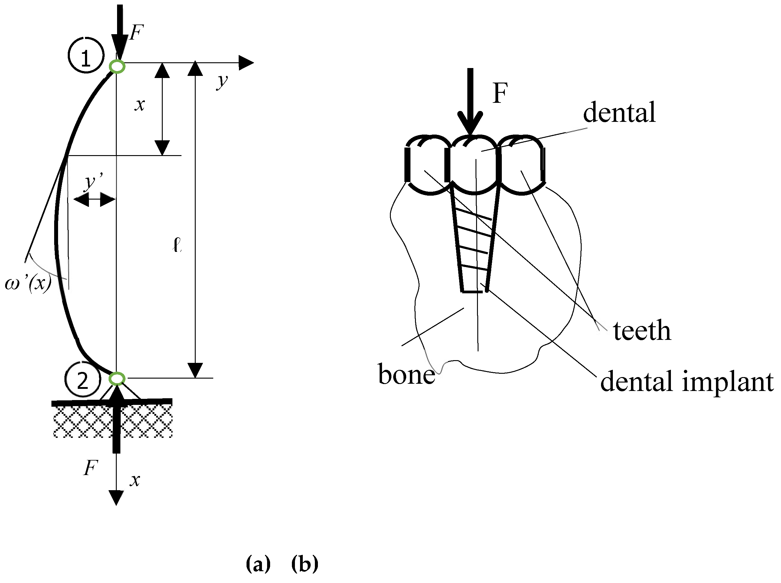
2.2.3. Calculus of dental implant as a double-articulated buckling bar with axial compression force on elastic environment through the TMM (Figure 4.)
The dental implant is assimilated with a double-articulated buckling bar with axial compression force on elastic environment at the bottom.
It can be defined the state vectors and the Transfer-Matrix of a straight bar, loaded with a concentrated force on the ends, as in
Figure 4., (a).
In section x, it can be written the deformation y.
It can be defined the state vector for a section
x of a bar, a column-vector with 4 elements as (61):
when:
- -
{V’(x)} = {V’}x is the state vector corresponding at the section x;
- -
y’(x) is the arrow corresponding at the section x;
- -
ω’(x) is the rotation corresponding at the section x;
- -
M’(x) is the bending moment corresponding at the section x;
- -
T’(x) is the cutting force corresponding at the section x.
For the first section, the left section, the origin, for
x = 0, the state vector is as (62):
At the last section on the right end, for
x = l, it can be written the state vector as (63):
The connection between the first section for
x = 0 and a certain section
x, can be made through the matrix relation (64):
with notations:
- -
{V’}x is the state vector corresponding to the section x;
- -
[T’]x is the Transfer-Matrix between the origin and the section x;
- -
{V’}0 is the state vector corresponding to the origin section, the section 0;
- -
[]x·{}x is a term wich corresponds to the exterior loads acting to the section x.
For a section
x, expressions (57), (58), (59) and (60) can be written as (65):
or, in the form of a matrix relation like (66):
For the last section, for
x = l, it can be written the matrix relation (66) as (67):
3. Results
3.1. Rezults for a double articulated buckling bar on rigid environment
With the conditions (35) the matrix relation (34) becomes as (68):
The banal solution (69) is removed:
The first accepted solution is (70):
and (71):
or, (72):
With (72) and notation (7) it can be written (73):
and the critical buckling force is (74):
value identical to that calculated in [
2] and [
3].
3.2. Rezults for a dental implant as a double articulated buckling bar on elastic environment
The elastic medium can be perfectly uniform and homogeneous. It must know the function for coefficient of elasticity of elastic environment k(x). It was considered a working hypothesis that the arrows at the two ends of the bar are initially 0.
It is possible to put the conditions at the two ends, for the doubly articulated right bar, as (75):
With (75) the matrix relation (67) becomes as (76):
or, (77):
with notations for each line:
- for the first line as (78):
- for the second line as (79):
- for the third line as (80):
for the fourth line as (81):
The matrix relations (76) or (77) can be written as a linear system of 4 equations with 4 unknowns and can be solved and it can be solved relatively easily, especially if software is designed to solve problems with TMM. The solutions allow to determine the critical buckling force for a double-jointed bar, with the lower joint on an elastic medium, subjected to compression by a vertical axial force, with which dental implant is assimilated into bone, bone being likened to an elastic environment.
4. Discussion
This study was done in two steps. Initially, the bar was considered as standing on a rigid environment, the conditions were set on the two end supports and the critical buckling force was determined, which is very important to find the most suitable material for making the respective dental implant. The second step consisted in studying the same doubly articulated bar subjected to compression by a concentrated vertical axial force. This time, it was considered that the joint at the lower end of the bar is on an elastic medium, the bone in which the implant is placed being considered as an elastic environment. In both situations, the modeling was done by TMM.
In the first case, the bar on the rigid environment, it was started from the differential equation of the deformed average fiber, which was derived twice, obtaining a characteristic equation, having as solution the expression of the arrow. This expression is derived four times and was obtained by the expressions for the rotation, bending moment and shear force in some section of the doubly articulated bar and required by a concentrated vertical axial compression force. For this case of the bar on a rigid environment, the four expressions for the arrow, rotation, bending moment and shear force were transcribed in a matrix relationship, written for a certain section x. The four elements (arrow, rotation, bending moment and shear force) compose a state vector associated with some section x. This state vector is obtained by multiplying the transfer matrix corresponding to section x with the state vector of origin section 0. Then, in this matrix relation, x = l was made, and the result was the state vector of the last section, the top section of the bar, depending on the transfer matrix and the state vector of the origin section 0. In this last matrix relationship, the conditions can be placed on the two articulated supports at the two ends of the bar. Then, the matrix relation can be developed into a linear system of four equations with four unknowns, which will have as solution the unknown elements of the two state vectors, the state vector of the first section, section 0 and the state vector of the last section, after which, the critical buckling force could be determined, a value also verified by the classic calculus from the Resistance of Materials.
The second case is the one with which the dental implant was assimilated, that is, a double articulated bar, the lower joint considering that it is on an elastic environment, the mandibular bone being assimilated with an elastic environment. This association is an original idea, which led to this study. In this case, in the differential equation of the deformed average fiber, a term involving the elasticity of the medium intervenes. And this time, the differential equation of the deformed average fiber is derived twice, obtaining as a solution the expression of the arrow in a section x. Then, the expression of the arrow is derived three times and the expressions of rotation, bending moment and cutting force are obtained. The four expressions (for arrow, rotation, bending moment and cutting force) were transcribed in a matrix relationship, just like in the case of the buckling bar on a rigid environment, for a section x. For x = l, it can be obtaining the state vector of the last section, the top section of the bar, depending on the transfer matrix and the state vector of the origin section 0 and now it is possible to put the conditions for the two ends. The matrix relation was developed in the form of a linear system of four equations with four unknowns. His solution gives as a solution the two remaining unknown elements of the state vector from the origin section and the two unknown elements of the state vector corresponding to the last section of the buckling bar on an elastic environment. Now, it is possible to calculate in any section of the bar a state vector with the four elements.
Being a very advantageous method, TMM offers the possibility to program the presented calculation algorithms and thus offers quick solutions in exceptional situations in orthodontics.
5. Conclusions
TMM is an easy and elegant method to solve different problems in various fields, especially where iterative calculations are needed and where the results must be obtained quickly. This work presents an original idea, to assimilate the dental implant as a buckling double articulated bar on elastic environment, the mandibular bone being assimilated as an elastic environment. The buckling bar is treated through the TMM. This work will serve to future research about dental implants. The TMM is very easy to program, for theoretical tests used to optimize the implants forms and after, in the future, to validate theoretical results with FEM and with experimental tests in laboratory and in situ too.
Author Contributions
Conceptualization, M.S., D.R., M.T., R.G. and O.O.; methodology, M.S., D.R., M.T. and O.O.; software, R.G., M.S. and I.B.; validation, D.R., R.G., P.O. and M.S.; formal analysis, M.S., D.R., M.T. and R.G.; investigation, D.R. and M.S.; resources, this research received no funding; data curation, M.S. and D.R.; writing—original draft preparation, M.S. and M.T.; writing—review and editing, M.S. and M.T.; visualization, M.S., D.R., M.T., R.G., O.O., P.O., and I.B.; supervision, M.S.; project administration, M.S.; funding acquisition, this research received no funding. All authors have read and agreed to the published version of the manuscript.
Funding
This research received no external funding.
Institutional Review Board Statement
Not applicable.
Informed Consent Statement
Not applicable.
Data Availability Statement
This is not the case.
Acknowledgments
to MDPI and to Technical University of Cluj-Napoca, Romania.
Conflicts of Interest
The authors declare no conflicts of interest.
References
- Gery, P.-M. & Calgaro, J.-A. Les Matrices-Transfert dans le calcul des structures. Eyrolles, Paris,1973.
- Suciu. M. & Tripa, M.-S. Strength of Materials, Ed. UTPress, Cluj-Napoca, Romania, 2024.
- Warren, C.Y. ROARK’’S Formulas for Stress & Strain, 6th ed.; McGrawHill Book Company: New York, NY, USA, 1989.
- Codrea, L.; Tripa, M.-S.; Opruţa, D.; Gyorbiro, R. & Suciu, M. Transfer-Matrix Method for Calculus of Long Cylinder Tube with Industrial Applications, Mathematics 2023, 11(17), 3756. [CrossRef]
- Suciu, M. About an approach by Transfer-Matrix Method (TMM) for mandible body bone calculus, Mathematics 2023, 11(2), 450. [CrossRef]
- Cojocariu-Oltean, O.; Tripa, M.-S.; Bărăian, I.; Rotaru, D.-I. & Suciu, M. Calculus of a monobloc dental bridge with two poles and two missing teeth as a beam, by Transfer-Matrix Method. Acta Technica Napocensis – Series: Applied Mathematics and Mecha-nics 2024, Vol 67, No 2, pp. 275-282.
- Cojocariu-Oltean, O.; Tripa, M.-S.; Bărăian, I.; Rotaru, D.-I. & Suciu, M. About Calculus Through the Transfer Matrix Method of a Beam with Intermediate Support with Applications in Dental Restorations, Mathematics 2024, 12(23), 3861. [CrossRef]
- Kui, A.; Chisnoiu, A. M.; Rotaru, D. I.; Zaharia, A. PROTHÈSES FIXÉES UNIDENTAIRES. Notions pratiques pour les préparations dentaires, Editura Medicală Universitară "Iuliu Haţieganu"; Cluj-Napoca, Romania, 2022.
- Tomescu, M. A.; Jäntschi, L.; Rotaru, D. I. Figures of Graph Partitioning by Counting, Sequence and Layer Matrices, Mathema-tics 2021, 9(12), 1419. [CrossRef]
- Bin, H.; Dogmei, L.; Jin, L.; Lei, M. & Pusong, M. A high order finite strip transfer matrix method for buckling analysis of single-branched cross-section thin-walled members. Thin-Walled Structures 2019, Vol. 135, pp. 1-11. Elsevier. [CrossRef]
- Bosshardt, D.; Champuis, V. & Buser, D. Osseointegration of titanium, titanium alloy and zirconia dental implants: Current knowledge and open questions. Periodontology 2017, 73, pp. 22–40.
- Buser, D.; Schenk, R.K.; Steinemann, S.; FioreIlini, J.P. & Fox, C.H. Influence of surface characteristics on bone integration of titanium implants. A histomorphometric study in miniature pigs. J. Biomed. Mater. Res. 1991, 25, pp. 889–902.
- Chen, L.-Y.; Cui, Y.-W. & Zhang, L.-C. Recent Development in Beta Titanium Alloys for Biomedical Applications. Metals 2020, 10, 1139.
- Javed, F.; Ahmed, H.B.; Crespi, R. & Romanos, G.E. Role of primary stability for successful osseointegration of dental implants: Factors of influence and evaluation. Interv. Med. Appl. Sci. 2013, 5, pp.162–167.
- Lan, T.H.; Du, J.K.; Pan, C.Y.; Lee, H.E. & Chung, W.H. Biomechanical analysis of alveolar bone stress around implants with different thread designs and pitches in the mandibular molar area. Clin. Oral. Investig. 2012, 16, pp. 363–369.
- Lu, Z.; Tao, D. & Quian, L. Buckling of Piles in Layered Soils by Transfer-Matrix Method, International Journal of Structural Stability and Dynamics 2021, Vol. 21. No. 8, 2150109. [CrossRef]
- Niinom, M. & Nakai, M. Titanium-Based Biomaterials for Preventing Stress Shielding between Implant Devices and Bone. Int. J. Biomater. 2011, 836587.
- O’Sullivan, D.; Sennerby, L. & Meredith, N. Influence of implant taper on the primary and secondary stability of osseointegrated titanium implants. Clin. Oral Implants. Res., 2004, 15, pp. 474–480.
- Pereira, G.K.R.; Guilardi, L.F.; Dapieve, K.S.; Kleverlaan, C.J.; Rippe, M. & Valandro, L.F. Mechanical reliability, fatigue strength and survival analysis of new polycrystalline translucent zirconia ceramics for monolithic restorations. J. Mech. Beh. Biomed. Mater. 2018, 85, pp. 57–65.
- Ryu, H.-S.; Namgung, C.; Lee, J.-H. & Lim, Y.-J. The influence of thread geometry on implant osseointegration under immediate loading: A literature review. J. Adv. Prosthodont. 2014, 6, 547–554.
- Sun, J.-p. & Li, Q.-n. Precise Transfer-Matrix Method for elastic-buckling analysis of compression bar. [J] Engineering Mechanics 2011, 28(7): 26-030.
- Suciu, M. About the Study of Bending Beam on Elastic Environment by Transfer-Matrix Method, Applied Mechanics and Materials 2012, Vol. 186, pp.149-155.
- Suciu, M. About Buckling Bio-Composite Sandwich Bars, Applied Mechanics and Materials 2013, Vol. 245, pp. 39-44.
- Suciu, M. An another approach for buckling calculus of dental implant as a bar on elastic environment by Transfer-Matrix Method (TMM). European Modern Studies Journal 2022, Vol. 6, no. 6, ISSN 2522-9400, www.journal-ems.com.
- Tripa, M.; Şolea, G.; Sorcoi, D.; Florescu, I.; Sorcoi, A.; Păunescu, D.; Bâlc, N. & Suciu, M. About buckling calculus of straight bars on elastic environment by Transfer-Matrix Method (TMM) for dental implants. In MATEC Web of Conferences 2018, Vol. 178, p. 04007. EDP Sciences.
- Trisi, P.; Beraldini, M.; Falco, A. & Vulpiani, M.P. Effect of Implant Thread Geometry on Secondary Stability, Bone Density, and Bone-to-Implant Contact: A Biomechanical and Histological Analysis. Implant. Dent. 2015, 24, pp. 384–391.
- Uporabo, B. A review of the surface modifications of titanium alloys for biomedical applications. Mater. Tehnol. 2017, 51, pp. 181–193.
- Velasco-Ortega, E.; Alfonso-Rodriguez, C.A.; Monsalve-Guii, L.; Espana-Lopez, A.; Jimenez-Guerra, A.; Garzon, I.; Alaminos, M. & Gil, F.J. Relevant aspects in the surface properties in titanium dental implants for the cellular viability. Mater. Sci. Eng. C 2016, 64, pp. 1–10.
- Watari, F.; Yokoyama, A.; Saso, F. & Uo, M. Fabrication and properties of functionally graded dental implant. Composites, Part B: Engineering 1997, Vol. 28, Issues 1-2, pp. 5-11, Elsevier. [CrossRef]
- Wilson, T.G. Jr.; Miiller, R.J.; Trushkowsky, R. & Dard, M. Tapered Implants in Dentistry: Revitalizing Concepts with Technology: A Review. Adv. Dent. Res. 2016, 28, pp. 4–9.
- Yilmaz, E., Feyza, N., Gokce, A. & Findik, F. (2020). Production and Characterization of a Bone-Like Porous Ti/Ti-Hydroxyapatite Functionally Graded Material. J. Mater. Eng. Perform. 2020, 29, pp. 6455–6467.
|
Disclaimer/Publisher’s Note: The statements, opinions and data contained in all publications are solely those of the individual author(s) and contributor(s) and not of MDPI and/or the editor(s). MDPI and/or the editor(s) disclaim responsibility for any injury to people or property resulting from any ideas, methods, instructions or products referred to in the content. |
© 2025 by the authors. Licensee MDPI, Basel, Switzerland. This article is an open access article distributed under the terms and conditions of the Creative Commons Attribution (CC BY) license (http://creativecommons.org/licenses/by/4.0/).