Submitted:
31 January 2025
Posted:
31 January 2025
You are already at the latest version
Abstract
Permanent magnet synchronous motors (PMSMs) are playing an increasing crucial role in industrial applications, where inaccurate system parameters can affect control performance and even threaten system stability. This paper aims to tackle the complex and cumbersome recognition algorithms for electrical and mechanical parameters of the PMSMs, which often result in long identification duration and low precision. We propose a full-parameter identification algorithm for PMSMs based on signal injection. This algorithm is simple and effective, easy to deploy, has a short identification duration, and high precision. It can achieve full parameter identification of resistance Rs, d-axis inductance Ld, q-axis inductance Lq, permanent magnet flux ψf, moment of inertia J, viscous damping coefficient Bm, and Coulomb friction coefficient Cm, contributing to the design and development of a high-performance PMSM servo control system. Firstly, this paper presents the identification algorithms for electrical and mechanical parameters. Then a simulation model is built using Maltab/Simulink. Finally, experiments are conducted on a 1.5kW built-in PMSM experimental platform. Both the simulation and experiments have verified the feasibility and effectiveness of the proposed method.
Keywords:
Electrical Parameter Identification
; Mechanical Parameter Identification
; Parameter Identification
; Permanent Magnet Synchronous Motor
1. Introduction
In recent years, Permanent Magnet Synchronous Motor (PMSM) has attracted extensive attention [1] and application in fields such as household appliances, new energy vehicles [2,3], and industrial machinery [4,5,6,7] due to its excellent characteristics like high power density, high efficiency, and wide speed regulation range. The high-performance control of the PMSM is particularly important. To achieve high-performance PMSM servo control systems, to facilitate high-precision torque, speed, and position control, it is necessary to obtain accurate key parameters such as stator resistance, dq-axis inductance, permanent magnet flux linkage, moment of inertia, viscous damping coefficient, and Coulomb friction, for designing excellent controllers [8,9]. Controllers commonly used in engineering, whether it is proportional-integral (PI) controller or modern controllers derived from modern control theory, all rely on motor parameters. For example, the design of the current loop controller parameters is directly related to resistance and inductance [10], the parameters of the speed loop and position loop controllers are directly related to the mechanical parameters and permanent magnet flux linkage [11,12,13]. The controller under parameter mismatch will cause the system response to be slower or larger overshoot, and due to the strong non-linearity friction torque when the speed crosses zero, the system will exhibit low-speed “creep” phenomenon. All of the above will greatly affect the control performance and tracking performance of the permanent magnet servo control system. Therefore, the study on parameter identification of PMSM is of significant importance for improving its control performance and meeting the demands in various fields [14].
Regarding the electrical parameters of PMSM, they can be mainly divided into offline identification and online identification. The offline electrical parameter identification methods mainly include finite element analysis and experimental measurement, in which the finite element analysis mainly used for motor design, but the influence of processing technology, etc., will bring some errors. The experimental measurement method can measure the current motor parameters accurately, but it is not conducive to the accurate identification of motor parameters under various operating conditions. Online electrical parameter identification methods mainly include recursive least squares method [15], model reference adaptive, extended Kalman filter, affine projection algorithm [16] and intelligent algorithms, etc. Recursive Least Square (RLS), due to its simple principle and easy to implement, is widely used in parameter identification. The accuracy of the model reference adaptive algorithm depends on the model accuracy and adaptation rate. However, when the identified parameters are many, the design of the adaptation rate is difficult. The extended Kalman filter, can suppress noise interference, but when the identified parameters are many, the computation is large. Affine projection algorithm, the computation is less than RLS, but the convergence speed is slower than RLS. Intelligent algorithms used in parameter identification mainly include particle swarm optimization algorithm [17] and neural network [18], their convergence speeds are fast, but the computation is large.
For the mechanical parameter identification of PMSM, similarly, they are mainly divided into offline identification [19,20,21,22] and online identification [23,24]. Offline mechanical parameter identification algorithm does not need to consider whether the application scenario is limited, and more researches exist. It mainly includes signal injection method [19,20], extended state observer method [21], and sliding mode observer method [22], etc. In signal injection methods, Papers [19,20] utilize the orthogonality of the cosine function and the symmetry of friction torque about speed, integrate the mechanical equation within a specific semi-period range of triangular function, and identify the system’s moment of inertia, viscous damping coefficient and Coulomb friction coefficient. However, the above methods all involve the integration of force to position, that is, parameter identification results depend on the tracking effect of the predetermined position trajectory. The operation of the algorithm needs real-time adjustment of the speed controller parameters, improving speed trajectory tracking effect, to enhance the identification accuracy. This leads to a long identification time, complicated algorithm implementation. Paper [20] identifies the three mechanical parameters without using a speed loop, by injecting a linearly increasing current to stimulate the system, comparing the actual rotor speed response and theoretical response, obtaining the moment of inertia and the Coulomb friction coefficient. According to the natural decay situation of the speed, the viscous damping coefficient can be obtained. Due to the rank deficient problem, two successive current stimuli are needed in the identification process, and the algorithm implementation is complicated; the implementation of this scheme requires the storage of speed response data, and the algorithm occupies a large storage space. Paper [21] designs an extended state observer, based on the Lyapunov stability theory to tune the observer parameters, and excites the system with a forward sine speed, obtaining more accurate identification results. But the algorithm control logic is complex, and calculation is large. Paper [22] applies a parallel sliding mode observer network to identify the three mechanical parameters of the servo system, and obtains good identification results under square wave speed excitation. Paper [25] points out that the excitatory effect of the high-order sliding mode algorithm on the unmodeled states of the system is significant, affecting the normal operation of the system and producing considerable negative impacts on the identification results. Papers [19,20] and [21,22] all involve speed loop control; on the premise of no prior information about the moment of inertia, the initial convergence situation and identification effect of the algorithm are not good. Online mechanical parameter identification algorithms usually need to adopt position control mode, they are restricted by the application scenario, and specific identification algorithms need to be designed for online identification. Paper [23], based on the traditional fixed-period integral moment of inertia identification method, proposed a variable-period moment of inertia identification method, overcoming the problems of poor identification results under irregular and slowly changing speed. However, this algorithm requires more zero-crossing speed cases, limiting the scope of application. Paper [24] addresses the problem of large range changes in system moment of inertia affecting normal system operation by treating the torque change caused by moment of inertia change equivalent to load torque disturbance, and effective suppression is achieved by designing a two-degree-of-freedom speed controller, obtaining excellent experimental results. Both Papers [23,24] did not carry out identification of friction coefficients such as viscous damping coefficient and Coulomb friction coefficient, which is not conducive to zero and low-speed operation of the system.
This article proposes a complete parameter identification algorithm based on signal injection for PMSM. Injecting a single high frequency voltage excitation, not using Fast Fourier Transform (FFT), but adopting a novel function amplitude and frequency extraction algorithm to acquire resistance and dq-axis inductance parameters. Based on the results of electrical parameter identification, a current loop is designed, and a constant current excitation is applied to the system. According to the electromechanical torque and speed response, the system’s three mechanical parameters and magnetic linkage parameters can be obtained. The identification precision of this complete parameter identification algorithm is independent of the system’s response to any particular signal. The algorithm is simple, effective, easy to implement, and requires a small amount of microcontroller memory. Both simulation results and experimental results have validated the scientific and validity of the proposed algorithm.
2. Mathematical Model of PMSM
Neglecting the eddy current loss and hysteresis loss of the PMSM, assuming that the excitation magnetic field generated by the permanent magnet and the armature reaction magnetic field generated by the stator winding are uniformly distributed in the air gap, then the voltage equation of the PMSM in the synchronous rotating d-q coordinate system is:
ud and uq are the voltage components of the motor on the d and q axes, respectively; id and iq are the current components of the motor on the d and q axes, respectively; p is the differentiation operator; Rs is the resistance of the motor’s stator winding; Ld and Lq are dq axis inductance; ωe is the angular velocity of the motor; ψf is the magnetic flux linkage of the motor rotor’s permanent magnet.
The electromagnetic torque equation and mechanical motion equation of PMSM are as below.
where, Te represents electromagnetic torque; pn is the pole pairs number; ωm is the mechanical angular velocity of the motor; J, Bm, Cm are respectively the moment of inertia, viscous damping coefficient and Coulomb friction coefficient of the servo system; TL is the load torque of the servo system. Considering the significant role of permanent magnet flux linkage ψf in the electro-mechanical energy conversion of PMSM, this paper will present parameter identification related to ψf in the mechanical parameters identification algorithm.
3. Electric Parameters Identification Algorithm Based on Sine Voltage Injection
This section will present the theory of Hilbert space, and the derivation process of identifying the resistance and dq-axis inductance parameters of the PMSM servo system. This algorithm can obtain the amplitude relationship and phase difference between the excitation signal and the response signal without FFT, greatly simplifying the calculation load, which is beneficial to engineering implementation.
3.1. Theory of Hilbert Space
L2[a, b] represents the set of all square-integrable functions on the closed interval [a, b], and l2 denotes the set of all square-summable sequences. For any real functions x, y∈L2[a, b], the function inner product is defined as follows.
the norm generated by this inner product is
If x ≠ 0, y ≠ 0, it can be derived from the Schwarz inequality.
then there is
hence, the angle between x and y can be defined as
when (x, y) = 0, θ = π/2.
Any element in L2[a, b] can be found as a unique corresponding element in l2 space, and vice versa, indicating the existence of homeomorphism. Therefore, L2[a, b] is topologically homeomorphic to l2. The space spanned by the trigonometric functions is dense in L2[a, b], which is a separable Hilbert space. Therefore, L2[a, b] is isometrically isomorphic to l2. In summary, L2[a, b] is both topologically homeomorphic and isometrically homeomorphic to l2. Hence, the angle defined by equation (8) is equivalent to the phase difference between two sine functions with the same frequency but different phases.
3.2. Principle of Electrical Parameter Identification Algorithm (EPIA)
The voltage equation of PMSM under high-frequency signal excitation is as follows [26].
Among them, udh and uqh are high-frequency voltage excitation; idh and iqh are the high-frequency components in the current response.
The high-frequency sinusoidal voltage injection into the motor is shown in Equation (10). The system control block diagram under electrical parameter identification is shown in Figure 1.
where and are voltage excitation signals; Uh and fh are the amplitude and frequency of the injected sine voltage signal, respectively; t is the time variable. Ignoring the non-linear factors of the inverter, at this point, the d and q axis voltage currents of the PMSM can be characterized by the following equation.
When the system is in steady state, using the form of phasor, the d and q axis voltage and currents can be represented as
Where j represents the imaginary unit; ωh denotes the angular velocity of the voltage injection signals in the d and q axes, where ωh = 2πfh; Ud,qh(jωh) and Id,qh(jωh) represent the phasor of the d and q axis voltage excitation signals and current response signals, respectively. Therefore, the identification result of the electrical parameters is shown as follows.
The moment when the system voltage and current reach steady state is defined as zero time, select an integer number of voltage and current periods, the total duration is T, and the base function is defined as follows on time t∈[0, T].
where ex and ey are the two basic functions at the angular velocity ωh = 2πfh; the coefficient 2/T is for normalization during the amplitude extraction process. Taking into consideration the 1.5 beat PWM period lag generated by the digital effect of the inverter, it is necessary to compensate for its phase. The ratio of the d and q axis voltage signals to the amplitude of the d and q axis current signals Amd,q, and the difference in the compensated phase φmd,q can be obtained as follows:
the translation in English is: Where Δφpwm = 3πTpwmfh. Consequently, the identification result of the electrical parameters is as follows.
4. Mechanical Parameter Identification Algorithm Based on Constant Current Excitation
To avoid the dependence of the mechanical parameter identification algorithm on the speed loop, and thus on the selection of the prior value of the system rotational inertia. This paper will present a mechanical parameter identification algorithm based on a constant current excitation, which can not only identify the rotational inertia, viscous damping coefficient, and Coulomb friction coefficient, but also obtain the magnitude of the permanent magnet flux linkage parameters. The algorithm is simple, efficient, and easy to implement, and the entire algorithm execution time does not exceed 3 seconds to complete.
Under no-load conditions in PMSM drive system, that is, the load torque TL = 0. Based on the results of electrical parameter identification in the previous section, the parameter tuning of the current loop PI controller can be realized. Figure 2 shows the control block diagram of the system’s mechanical parameter identification algorithm. The following current excitation is applied to the system.
where and represent current excitation signals; IQ is the constant value stimulating the PMSM drive system. To fully stimulate the system, this paper sets IQ as the rated current IN, but it is important to note that this is not a prerequisite condition.
The whole identification process includes three stages: the acceleration stage, constant speed stage, and deceleration stage. In the acceleration phase, the current PI of the drive system will quickly reach the limit value, and the rotor will start to accelerate in rotation. Then, as the speed increases, the voltage limit circle begins to shrink, and the actual q-axis current will decrease accordingly until the electromagnetic torque is exactly equal to the friction torque, and the system speed remains stable, which is the constant speed stage. After maintaining a brief constant speed operation, the inverter six switches are immediately forced off, and due to the PMSM losing power, the rotor naturally decelerates to zero, which is known as the deceleration stage. Figure 3 provides a schematic diagram of the rotor’s speed response in these three stages, and Figure 4 provides a schematic diagram of the voltage and current limit circles and the current working point changes during different stages of the mechanical parameter identification algorithm.
During the steady-state operation process and considering that the system adopts the id = 0 control strategy, the q-axis voltage equation of the system is as follows.
Considering the noise pollution in the drive system, this paper uses an integral operator to identify the magnetic linkage of the permanent magnet, with the identification values as follows.
Integrating the mechanical equation (3) of the PMSM drive system over the time [t1, t2], we can obtain
From the above analysis, it can be concluded that if the system rotational speed is always positive, then
Among them, ωm(t)=ωm (t2)-ωm (t1), θm(t)=θm (t2)- θm (t1), t= t2-t1. According to the acceleration phase (ta, tb), the uniform speed phase (tc, td) and the deceleration phase (te, tf), these three phases, combined with equation (26), it can be concluded.
The mechanical parameter identification results can be obtained from equation (27), as shown in the following formula:
Among them, J, Bm and Cm with a hat are the identified values of moment of inertia, viscous damping coefficient and Coulomb friction coefficient respectively.
5. Simulation and Experimental Verification
This section will conduct simulation analysis and experimental verification through Matlab/Simulink software and PMSM drive system based on TMS320F28335, respectively. The related parameters of the PMSM drive system are shown in Table 1.
5.1. Matlab/Simulink Simulation Analysis
Under no-load conditions, voltage signals are injected into the d and q axes of the PMSM, respectively, = Uhsin(2πfht) and = Uhsin(2πfht), where Uh = 100V and fh = 500Hz. Figure 5 shows the reference values of d and q axis voltage and the actual values of current under the steady state of PMSM; Figure 6 shows the selected basis functions ex and ey. The simulation results of the electrical parameter identification algorithm are shown in Table 2.
The bandwidth of the current loop is set to fc, and the PI parameters can be tuned based on the identified values Rs and Ld,q. The tuning of d and q axis current loop PI parameters is as follows:
Here, Kpd,q represents the P parameter in the PI controllers for d and q axis currents, while Kid,q represents the I parameter. In the Matlab/Simulink simulation, the bandwidth of the current loop is set to fc = 1000Hz, and the upper and lower limits of PI are 179.56V and -179.56V respectively. Figure 7 shows the changes of relevant variables during the mechanical parameter identification process. A rated current excitation of = 0 and = iqN is applied to accelerate the PMSM rotor. This is then maintained at a constant speed and eventually decoupled at t = 1s, allowing the motor rotor to slow down freely to zero. The time required for identification is short, approximately completing the mechanical parameter identification in 1.8s. Specifically, the acceleration phase takes about 0.05s, the constant speed phase lasts about 1s, and the natural deceleration phase takes approximately 0.8s. We may choose (ta, tb) = (0, 0.003s), (tc, td) = (0.200s, 0.800s) and (te, tf) = (1.050, 1.850s) respectively as the acceleration, constant speed, and deceleration phases. The simulation results of the mechanical parameter identification algorithm are as shown in Table 3.
5.2. Experimental Validation
To verify the feasibility and effectiveness of the full-parameter identification algorithm based on signal injection proposed in this paper, a PMSM driving system experimental platform was independently developed and built with TMS320F28335 as the main control chip, as shown in Figure 8. This experimental platform includes a 1.3kW PMSM and a towing machine produced by Weiong Technology Ltd., which are connected by a torque meter and a coupling, and the controlled motor is powered by a bi-directionally programmable DC power supply IT6006C-500-40. All relevant experimental data is transmitted to the upper computer in real-time at a sampling rate of 10 kHz through the RS485 module using the DSP’s serial communication module, with a baud rate of 5 Mbps.
Voltage signals are injected into the d axis and q axes of the PMSM respectively, being = Uhsin(2πfht) and = Uhsin(2πfht), where Uh = 100V and fh = 500Hz. 20 electrical parameter identification experiments were conducted. Figure 9 displays the results of the electrical parameter identification experiment. In particular, Figure 9(a) and Figure 9(b) show the curve of the voltage reference values and the actual current values of the d and q axes under steady state conditions of the PMSM in one of the experiments. Figure 9(c) depicts the results of the electrical parameter identification for these 20 experiments.
The current loop bandwidth was set to fc = 500Hz and fc = 1000Hz, and current excitation with intensities of = 0.5IN and = IN were conducted respectively, resulting in four sets of comparative experiments. After the rotational speed of the four operating conditions stabilized, each was maintained at a constant speed for 1s. Subsequently, the six switches of the inverter were forcibly shut off immediately, disabling the inverter. Each operating condition was experimented 20 times. Figure 10 illustrates the change trend of relevant variables under different conditions in one of the experiments; Figure 11 presents the identification results of the magnetic linkage, where (a) represents the identification results of the permanent magnetic linkage under various conditions, and (b) the changes in magnetic linkage with the number of experiments; Figure 12 exhibits the identification results of the inertia, damping, and Coulomb friction, where (a) shows the identification results of the rotating inertia under different conditions, and (b) the identification results of the viscous damping coefficient Bm and Coulomb friction coefficient Cm in one of the experiments.
The experimental results show that the relative errors between the identified values and the true values of Rs, Ld and Ld do not exceed 8%, which validates the effectiveness of the electrical parameter identification algorithm proposed in this paper. This method is quick in identification, simple in algorithm, and strong in noise reduction. The identified value of ψf has a certain difference from the nominal value, which slowly decreases with the increase of experimental times. This is because the operation of the motor causes the temperature to rise, which in turn affects the size of the permanent magnet flux linkage [27]. Although the flux linkage size is influenced by temperature, the identified value is still accurate. This is because the system identifies the parameters of the flux linkage during steady running conditions. The system’s voltage limit circle controls the actual current size, making almost all voltages used to overcome back electromotive force, making the characteristics of permanent magnet flux linkage prominent and enabling accurate flux linkage identification. This algorithm, thanks to the use of the integral operator, has strong resistance to noise. The identified values of J, Bm, and Cm are influenced and changed by the bandwidth and intensity of current loop. This is due to the more noticeable Stribeck effect of the rotor in the zero-low-speed area [28], that is, there is a nonlinear part in the friction-torque curve in the zero-low-speed region. Because of the difference in the bandwidth and intensity of the current loop, the system responds differently to current, which in turn affects the response of system speed and position, and then affects the identification results of mechanical parameters. The mechanical parameter identification algorithm based on the momentum theorem that proposed in this paper aims to optimally identify system mechanical parameters under the premise of equal impulse.
6. Conclusions
This paper proposes a full parameter identification algorithm for PMSMs based on signal injection. The algorithm consists of two parts: an electrical parameter identification algorithm based on high-frequency sinusoidal voltage injection, and a mechanical parameter identification algorithm based on constant current excitation. The electrical parameter identification algorithm doesn’t involve a current loop and uses functional analysis theory to extract the amplitude and phase of the sinusoidal signal, obviating the need for FFT algorithm, thereby greatly simplifying the computation and algorithm complexity, and offering accurate and swift identification with high efficiency. The mechanical parameter identification algorithm only involves the current loop, is independent of the speed loop, requires no prior values of the rotational inertia, thus simplifying the implementation and deployment of the mechanical parameter identification algorithm. Additionally, this algorithm does not need to track any specific trajectory, the identification accuracy does not depend on the tracking effect, but depends on the accuracy of the rotational speed, current sampling and microcontroller oscillator frequency. The accurate identification of the magnetic linkage of the permanent magnet also provides a crucial guarantee for the high-accuracy identification of J, Bm and Cm.
References
- Tarczewski, T.; Szczepanski, R.; Erwinski, K.; Hu, X.; Grzesiak, L.M. A Novel Sensitivity Analysis to Moment of Inertia and Load Variations for PMSM Drives. IEEE Trans. Power Electron. 2022, 37, 13299–13309. [Google Scholar] [CrossRef]
- Yang, Z.; Shang, F.; Brown, I.P.; Krishnamurthy, M. Comparative Study of Interior Permanent Magnet, Induction, and Switched Reluctance Motor Drives for EV and HEV Applications. IEEE Trans. Transp. Electrification 2015, 1, 245–254. [Google Scholar] [CrossRef]
- Athavale, A.; Sasaki, K.; Gagas, B.S.; Kato, T.; Lorenz, R.D. Variable Flux Permanent Magnet Synchronous Machine (VF-PMSM) Design Methodologies to Meet Electric Vehicle Traction Requirements with Reduced Losses. IEEE Trans. Ind. Appl. 2017, 53, 4318–4326. [Google Scholar] [CrossRef]
- Sun, B.; Chen, Z.; Gao, C.; Haddad, A.; Liang, J.; Liu, X. A Power Decoupling Control for Wind Power Converter Based on Series-Connected MMC and Open-Winding PMSG. IEEE Trans. Ind. Electron. 2021, 69, 8091–8101. [Google Scholar] [CrossRef]
- Balbino, A.J.; Nora, B.d.S.; Lazzarin, T.B. An Improved Mechanical Sensorless Maximum Power Point Tracking Method for Permanent-Magnet Synchronous Generator-Based Small Wind Turbines Systems. IEEE Trans. Ind. Electron. 2021, 69, 4765–4775. [Google Scholar] [CrossRef]
- Li, J.; Xia, Y.; Qi, X. On the Necessity, Scheme, and Basis of the Linear–Nonlinear Switching in Active Disturbance Rejection Control. IEEE Transactions on Industrial Electronics 2017, 64, 1425–1435. [Google Scholar] [CrossRef]
- Yu, Y.; Pei, Y.; Chai, F.; Doppelbauer, M. Performance Comparison Between Permanent Magnet Synchronous Motor and Vernier Motor for In-Wheel Direct Drive. IEEE Trans. Ind. Electron. 2022, 70, 7761–7772. [Google Scholar] [CrossRef]
- Wang, Q.; Wang, G.; Zhao, N.; Zhang, G.; Cui, Q.; Xu, D.G. An Impedance Model-Based Multiparameter Identification Method of PMSM for Both Offline and Online Conditions. IEEE Trans. Power Electron. 2020, 36, 727–738. [Google Scholar] [CrossRef]
- Wang, Y.; Liao, W.; Huang, S.; Zhang, J.; Yang, M.; Li, C.; Huang, S. A Robust DPCC for IPMSM Based on a Full Parameter Identification Method. IEEE Trans. Ind. Electron. 2022, 70, 7695–7705. [Google Scholar] [CrossRef]
- An, X.; Liu, G.; Chen, Q.; Zhao, W.; Song, X. Adjustable Model Predictive Control for IPMSM Drives Based on Online Stator Inductance Identification. IEEE Trans. Ind. Electron. 2021, 69, 3368–3381. [Google Scholar] [CrossRef]
- Yang, S.-M.; Lin, K.-W. Automatic Control Loop Tuning for Permanent-Magnet AC Servo Motor Drives. IEEE Trans. Ind. Electron. 2015, 63, 1499–1506. [Google Scholar] [CrossRef]
- Erturk, F.; Akin, B. Inertia Estimation and Speed Loop Auto-Tuning for IPMSM Self-Commissioning. IEEE Trans. Energy Convers. 2019, 34, 1706–1714. [Google Scholar] [CrossRef]
- Choi, J.-W.; Lee, S.-C.; Kim, H.-G. Inertia identification algorithm for high-performance speed control of electric motors. Iee Proc. - Electr. Power Appl. 2006, 153, 379–386. [Google Scholar] [CrossRef]
- Y, Yu.; X, Huang.; Z, Li. Full Parameter Estimation for Permanent Magnet Synchronous Motors. IEEE Transactions on Industrial Electronics 2022, 69, 4376-4386.
- Q, Wang.; G, Wang.; N, Zhao. An Impedance Model-Based Multiparameter Identification Method of PMSM for Both Offline and Online Conditions. IEEE Transactions on Power Electronics 2021, 36, 727-738.
- M S, Rafaq.; F, Mwasilu.; J, Kim. Online Parameter Identification for Model-Based Sensorless Control of Interior Permanent Magnet Synchronous Machine. IEEE Transactions on Power Electronics 2017, 32, 4631-4643.
- Z H, Liu.; H L, Wei Li; H, X. Global Identification of Electrical and Mechanical Parameters in PMSM Drive Based on Dynamic Self-Learning PSO.IEEE Transactions on Power Electronics 2018, 33, 10858-10871.
- K, Liu.; Z Q, Zhu.; Stone, D A. Parameter Estimation for Condition Monitoring of PMSM Stator Winding and Rotor Permanent Magnets. IEEE Transactions on Industrial Electronics 2013, 60, 5902-5913.
- Kim, S. Moment of Inertia and Friction Torque Coefficient Identification in a Servo Drive System. IEEE Trans. Ind. Electron. 2018, 66, 60–70. [Google Scholar] [CrossRef]
- Zuo, Y.; Mei, J.; Zhang, X.; Lee, C.H.T. Simultaneous Identification of Multiple Mechanical Parameters in a Servo Drive System Using Only One Speed. IEEE Trans. Power Electron. 2020, 36, 716–726. [Google Scholar] [CrossRef]
- Yang, B.; Song, Y.; Xie. Speed-Controller-Independent Mechanical Parameter Identification in SPMSM Drive Achieved via Signal Injection. IEEE Transactions on Industrial Electronics 2023, 70, 1282–1297.
- Yang, B.; Song, Y.; Xie. Online Parallel Estimation of Mechanical Parameters for PMSM Drives via a Network of Interconnected Extended Sliding-Mode Observers. IEEE Transactions on Power Electronics 2021, 36, 11818–11834.
- Chen, Y.; Yang, M.; Long, J. A moderate online servo controller parameter self-tuning method via var-iable-period inertia identification. IEEE Transactions on Power Electronics 2019, 34, 12165–12180. [Google Scholar] [CrossRef]
- Fan, Y.; Chen, J.; Zhang, Q.; Cheng, M. An Improved Inertia Disturbance Suppression Method for PMSM Based on Disturbance Observer and Two-Degree-of-Freedom PI Controller. IEEE Trans. Power Electron. 2022, 38, 3590–3599. [Google Scholar] [CrossRef]
- Utkin, V. Discussion Aspects of High-Order Sliding Mode Control. IEEE Trans. Autom. Control. 2015, 61, 829–833. [Google Scholar] [CrossRef]
- Wang, Q.; Wang, G.; Zhao, N.; Zhang, G.; Cui, Q.; Xu, D.G. An Impedance Model-Based Multiparameter Identification Method of PMSM for Both Offline and Online Conditions. IEEE Trans. Power Electron. 2020, 36, 727–738. [Google Scholar] [CrossRef]
- Gulec, M.; Aydin, M.; Nerg, J.; Lindh, P.; Pyrhonen, J.J. Magneto-Thermal Analysis of an Axial-Flux Permanent-Magnet-Assisted Eddy-Current Brake at High-Temperature Working Conditions. IEEE Trans. Ind. Electron. 2020, 68, 5112–5121. [Google Scholar] [CrossRef]
- Wang, C.; Peng, J.; Pan, J. A Novel Friction Compensation Method Based on Stribeck Model With Fuzzy Filter for PMSM Servo Systems. IEEE Trans. Ind. Electron. 2023, 70, 12124–12133. [Google Scholar] [CrossRef]
Figure 1.
Electric parameter identification system control block diagram.
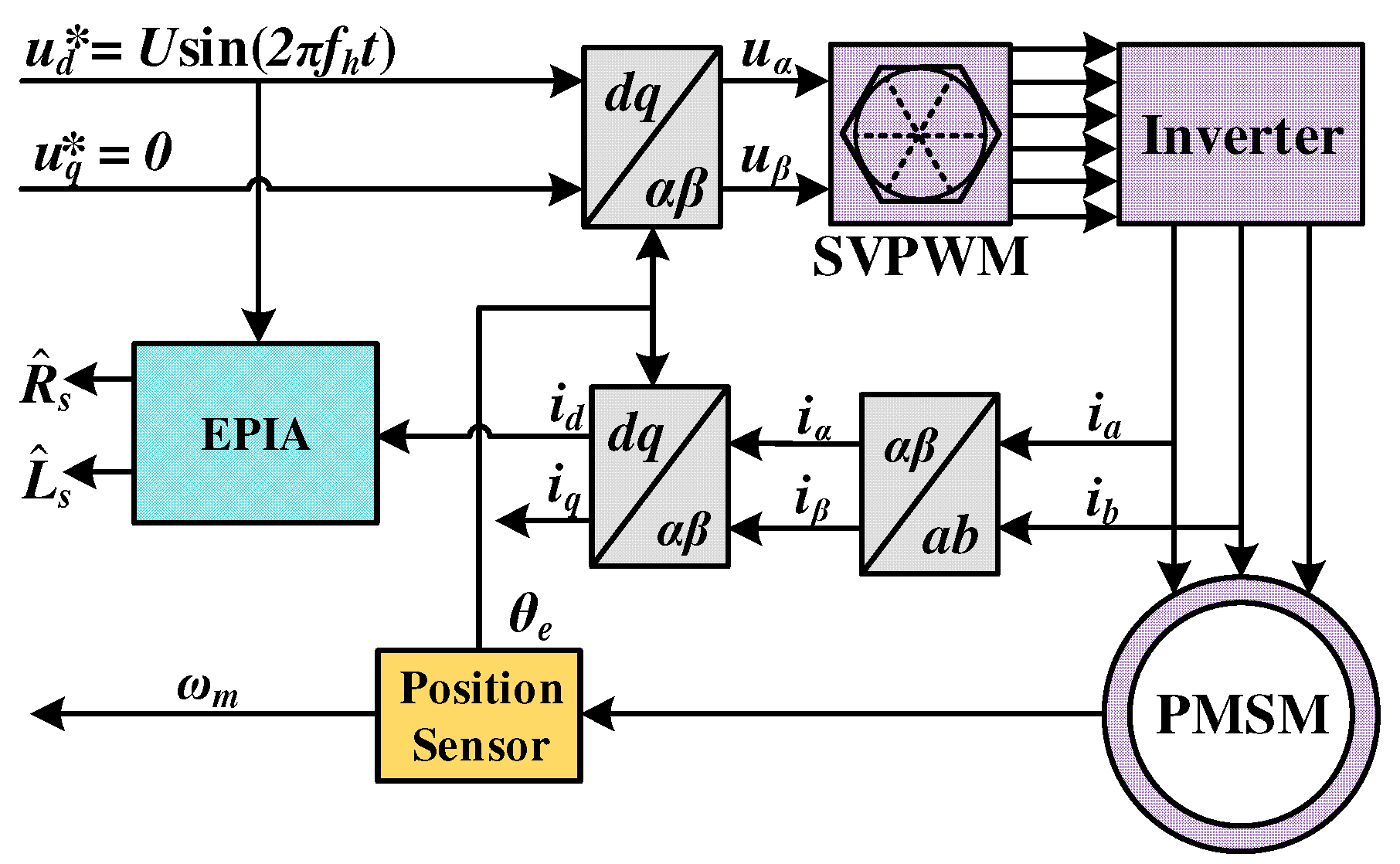
Figure 2.
Mechanical parameter identification system control block diagram.
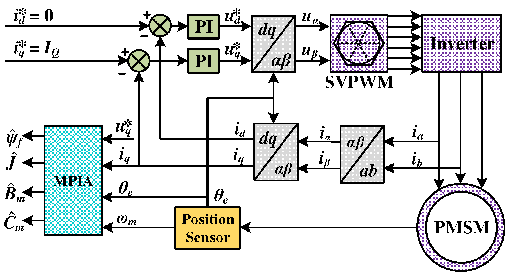
Figure 3.
Schematic diagram of rotor speed response in the process of mechanical parameter identification.
Figure 3.
Schematic diagram of rotor speed response in the process of mechanical parameter identification.
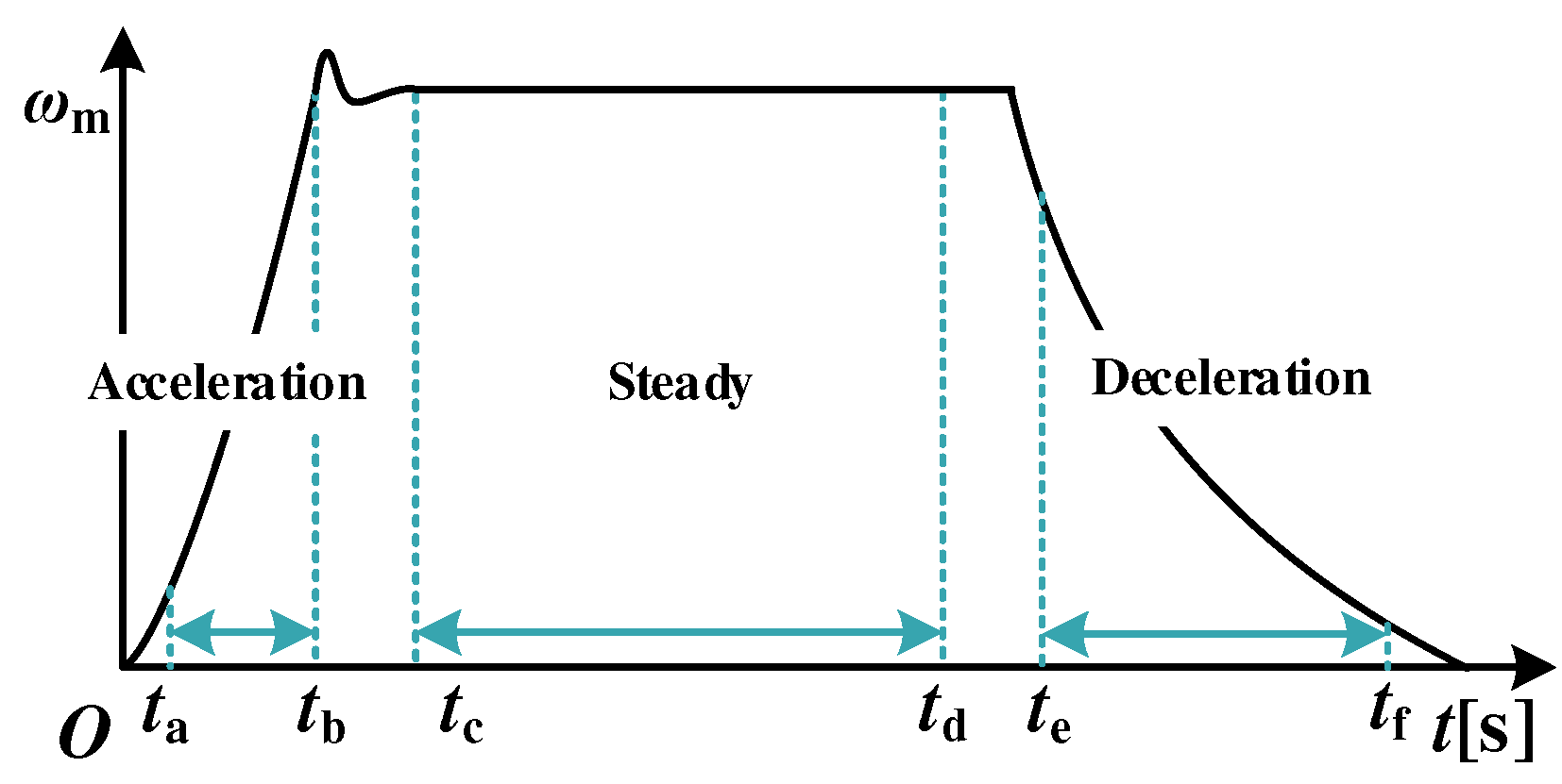
Figure 4.
Schematic diagram of speed response in the process of mechanical parameter identification. (a) Acceleration stage; (b) Steady stage; (c) Deceleration stage.
Figure 4.
Schematic diagram of speed response in the process of mechanical parameter identification. (a) Acceleration stage; (b) Steady stage; (c) Deceleration stage.
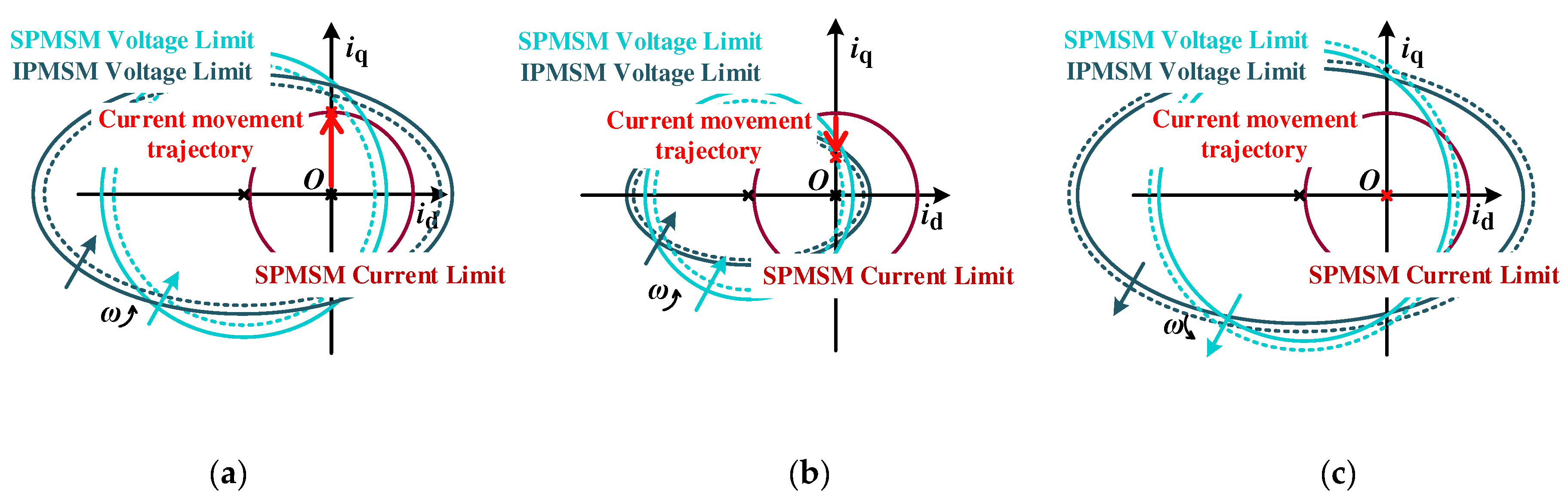
Figure 5.
Figure 5.Dq axis voltage reference values and current measurement curve. (a) D-axis; (b) Q-axis.
Figure 5.
Figure 5.Dq axis voltage reference values and current measurement curve. (a) D-axis; (b) Q-axis.
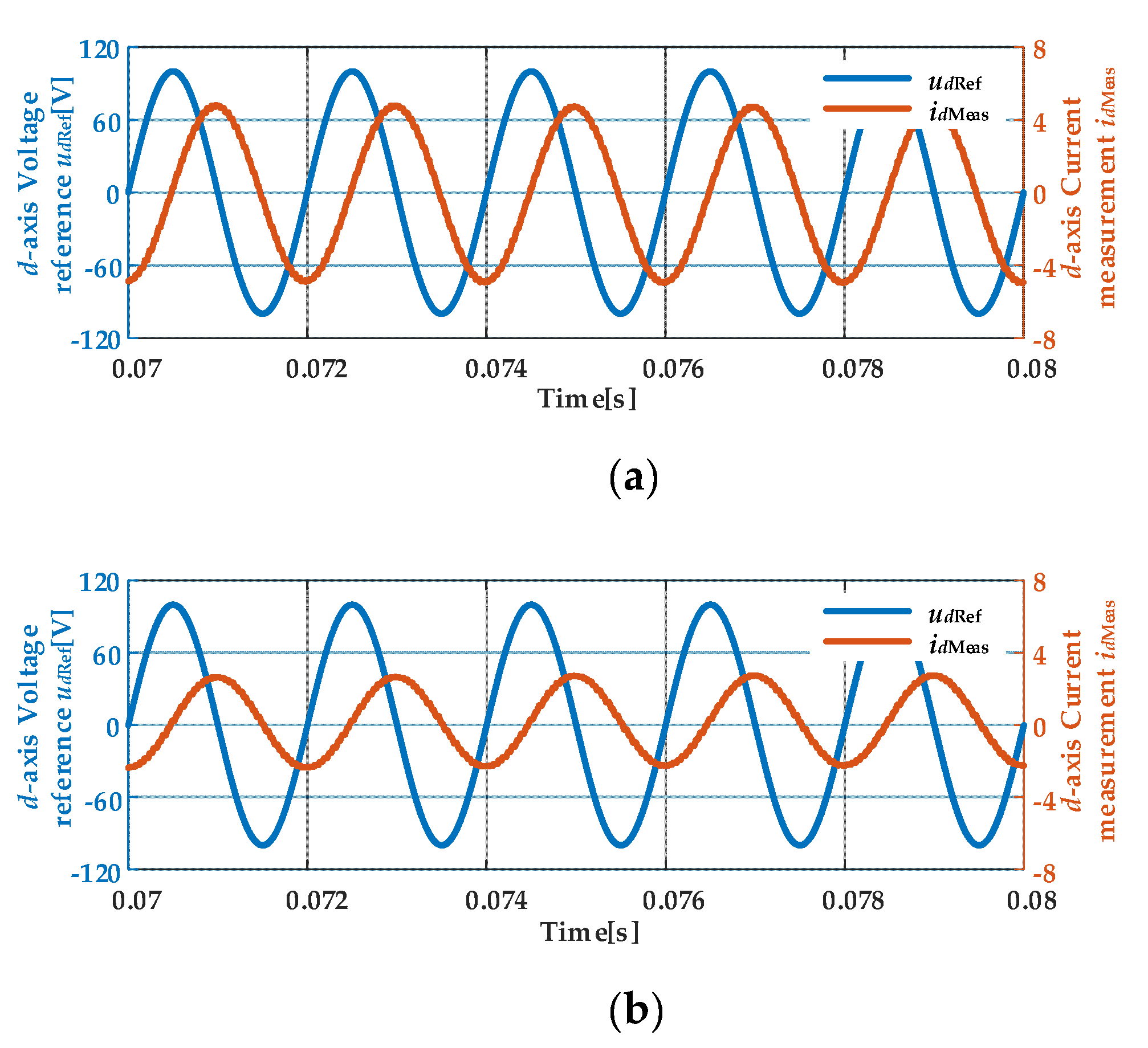
Figure 6.
Base functions ex and ey.
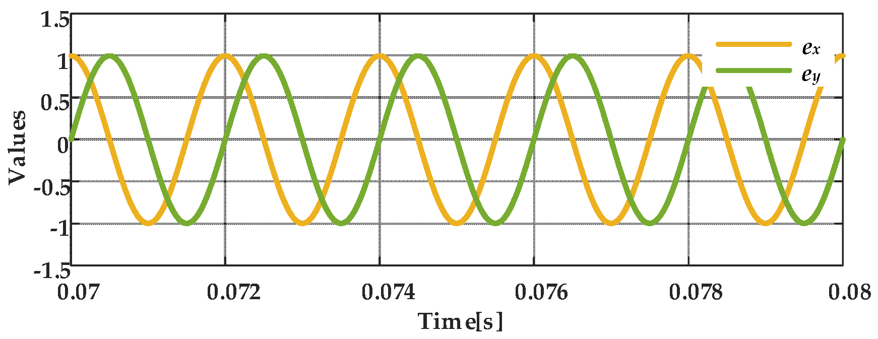
Figure 7.
The changing curve of relevant variables during the process of mechanical parameter identification.
Figure 7.
The changing curve of relevant variables during the process of mechanical parameter identification.
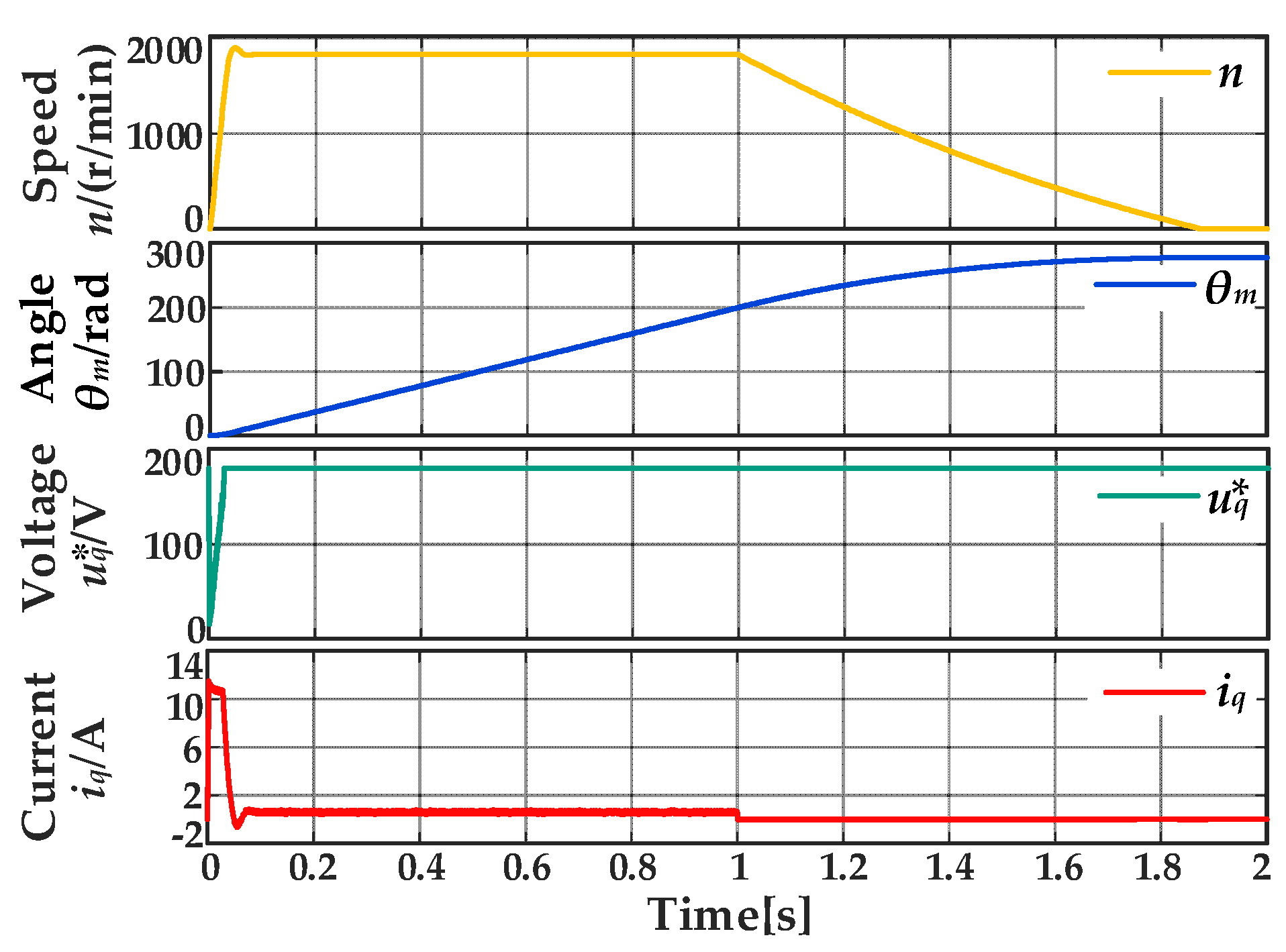
Figure 8.
TMS320F28335-based drive system experimental platform.
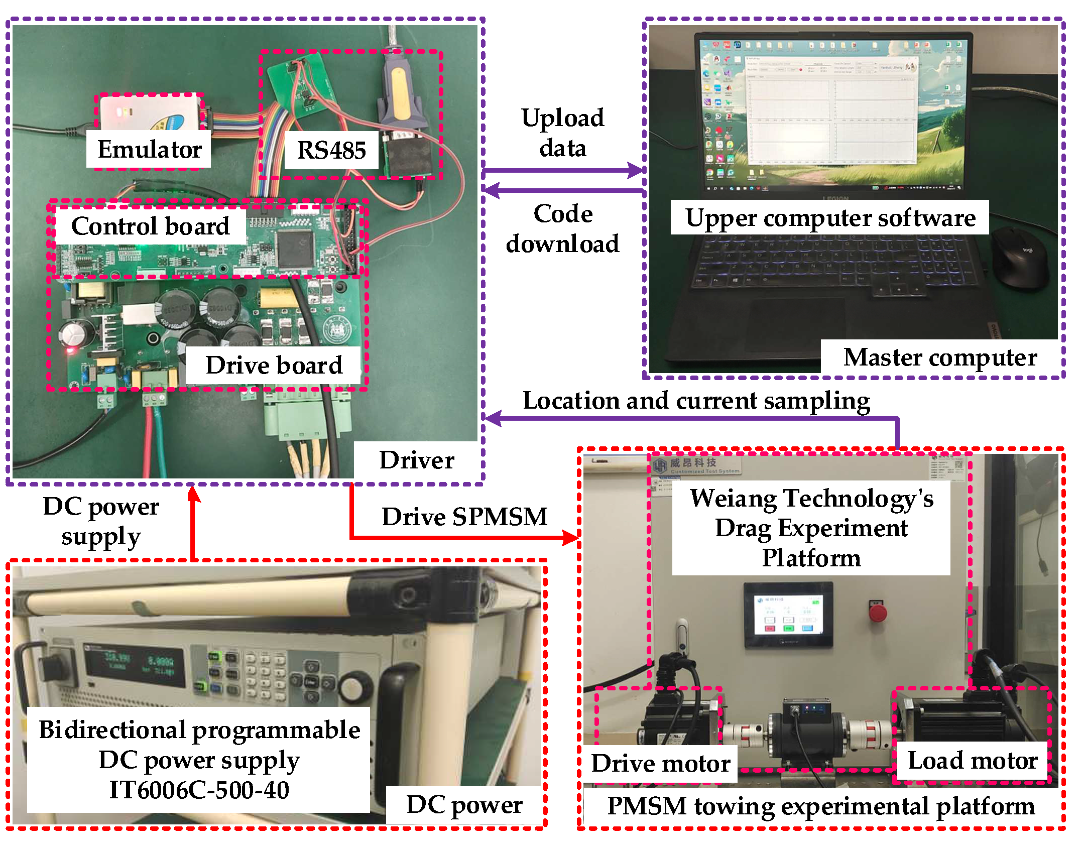
Figure 9.
Waveform of electrical parameter identification algorithm experiment. (a) D-axis voltage reference value and current measurement value; (b) Q-axis voltage reference value and current measurement value; (c) Results of 20 identification experiments of Rs and Ldq.
Figure 9.
Waveform of electrical parameter identification algorithm experiment. (a) D-axis voltage reference value and current measurement value; (b) Q-axis voltage reference value and current measurement value; (c) Results of 20 identification experiments of Rs and Ldq.
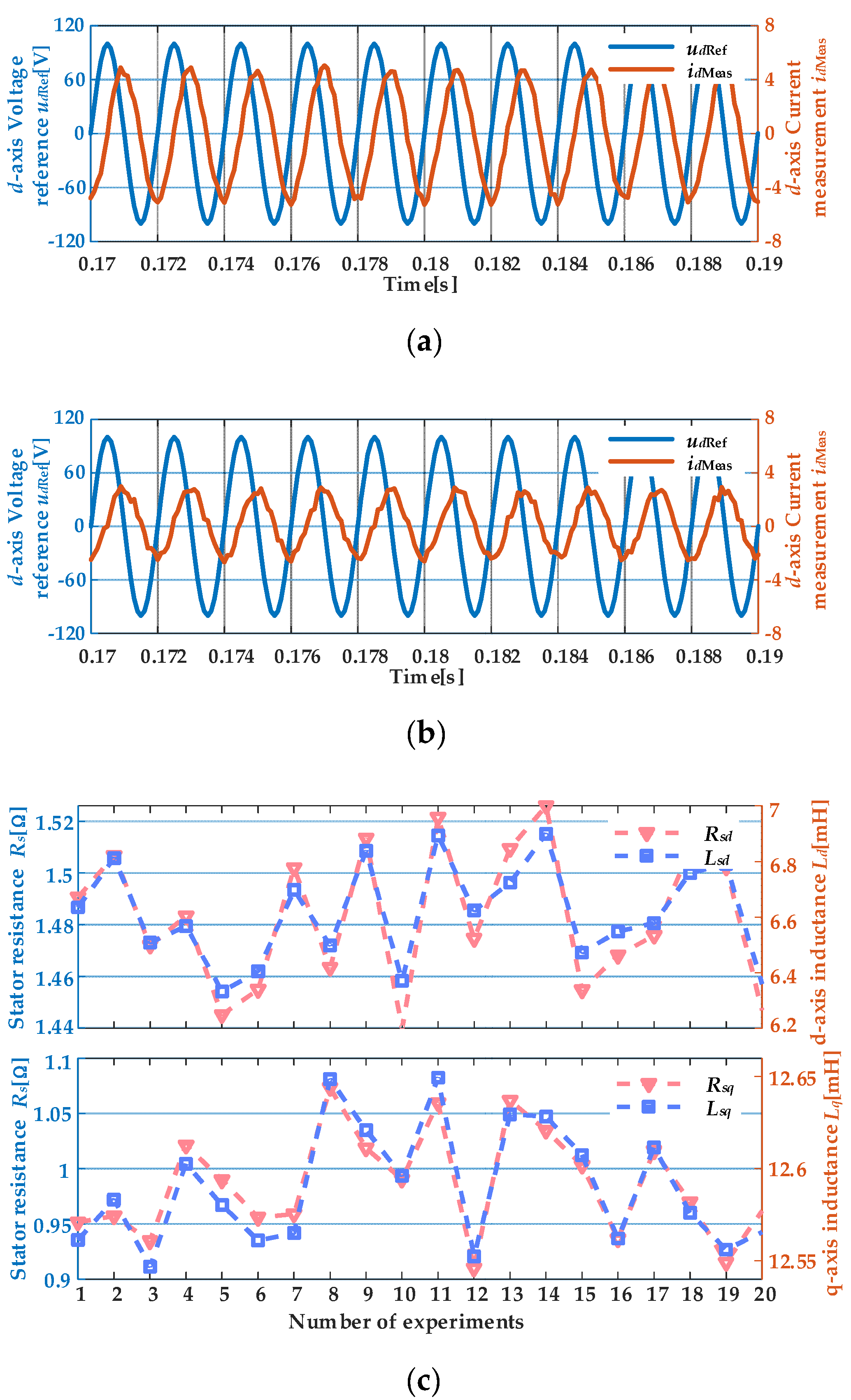
Figure 10.
System response under different current loop bandwidths and different current intensities stimulation. (a) fc=500Hz, = 0.5IN; (b) fc=500Hz, = 1.0IN; (c) fc=1000Hz, = 0.5IN; (d) fc=1000Hz, = 1.0IN.
Figure 10.
System response under different current loop bandwidths and different current intensities stimulation. (a) fc=500Hz, = 0.5IN; (b) fc=500Hz, = 1.0IN; (c) fc=1000Hz, = 0.5IN; (d) fc=1000Hz, = 1.0IN.
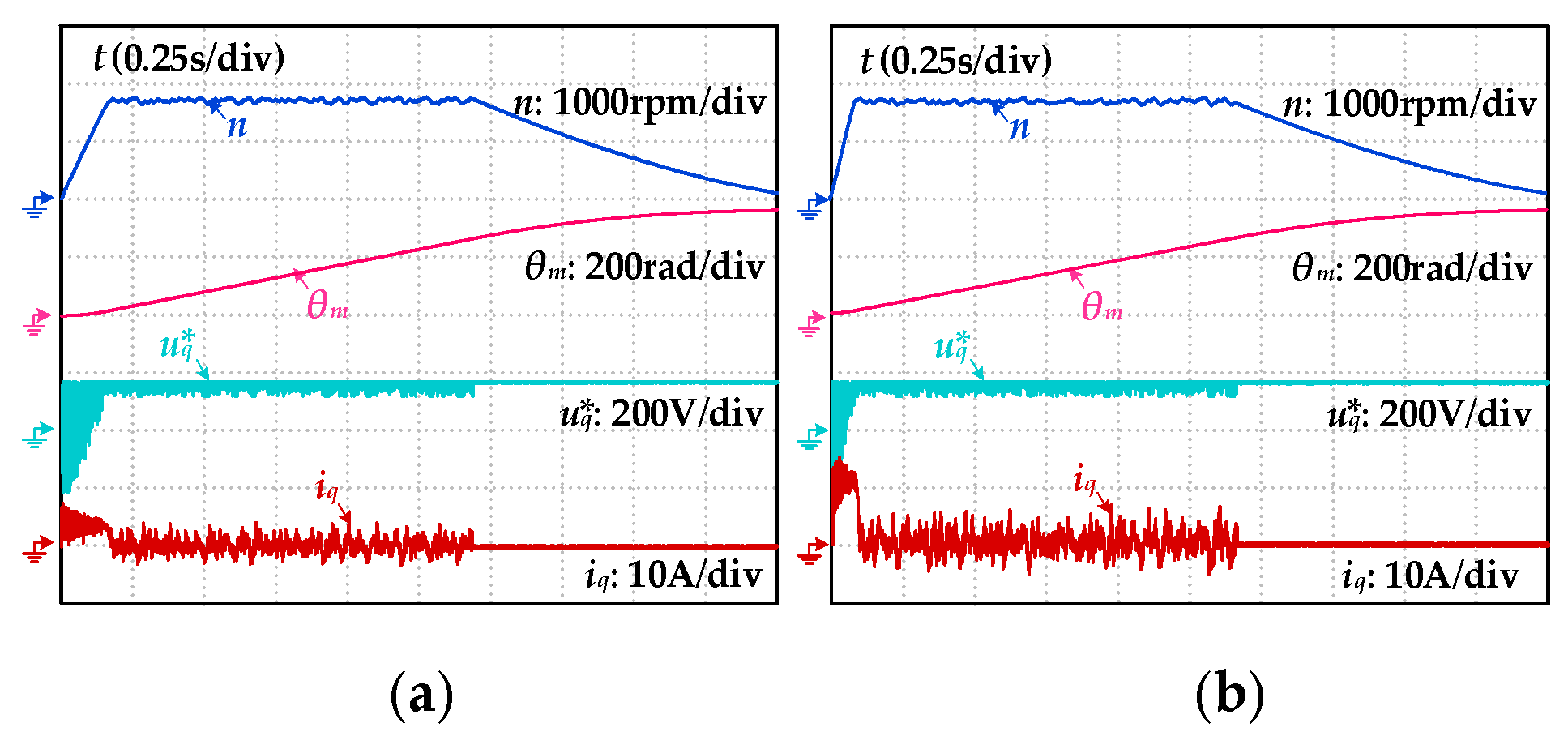
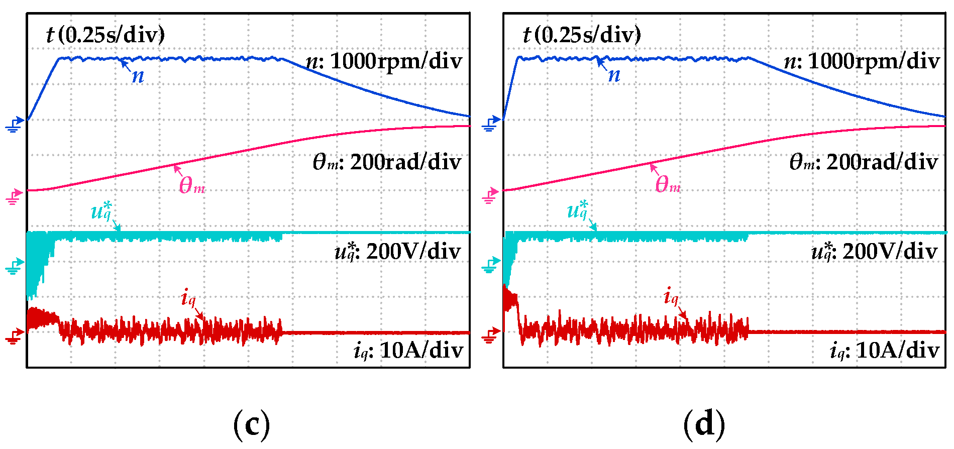
Figure 11.
Recognition result of permanent magnet flux ψf. (a) Experimental results of magnetic chain identification under different conditions; (b) Results of the 80 magnetic flux linkage identification experiments.
Figure 11.
Recognition result of permanent magnet flux ψf. (a) Experimental results of magnetic chain identification under different conditions; (b) Results of the 80 magnetic flux linkage identification experiments.
Figure 12.
Identification results of J, Bm, and Cm mechanical parameters. (a) Experimental results of inertia identification under different conditions; (b) Identification experiment results of viscous damping and Coulomb friction under different conditions.
Figure 12.
Identification results of J, Bm, and Cm mechanical parameters. (a) Experimental results of inertia identification under different conditions; (b) Identification experiment results of viscous damping and Coulomb friction under different conditions.
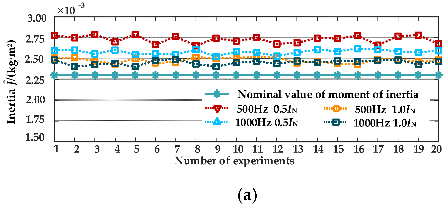
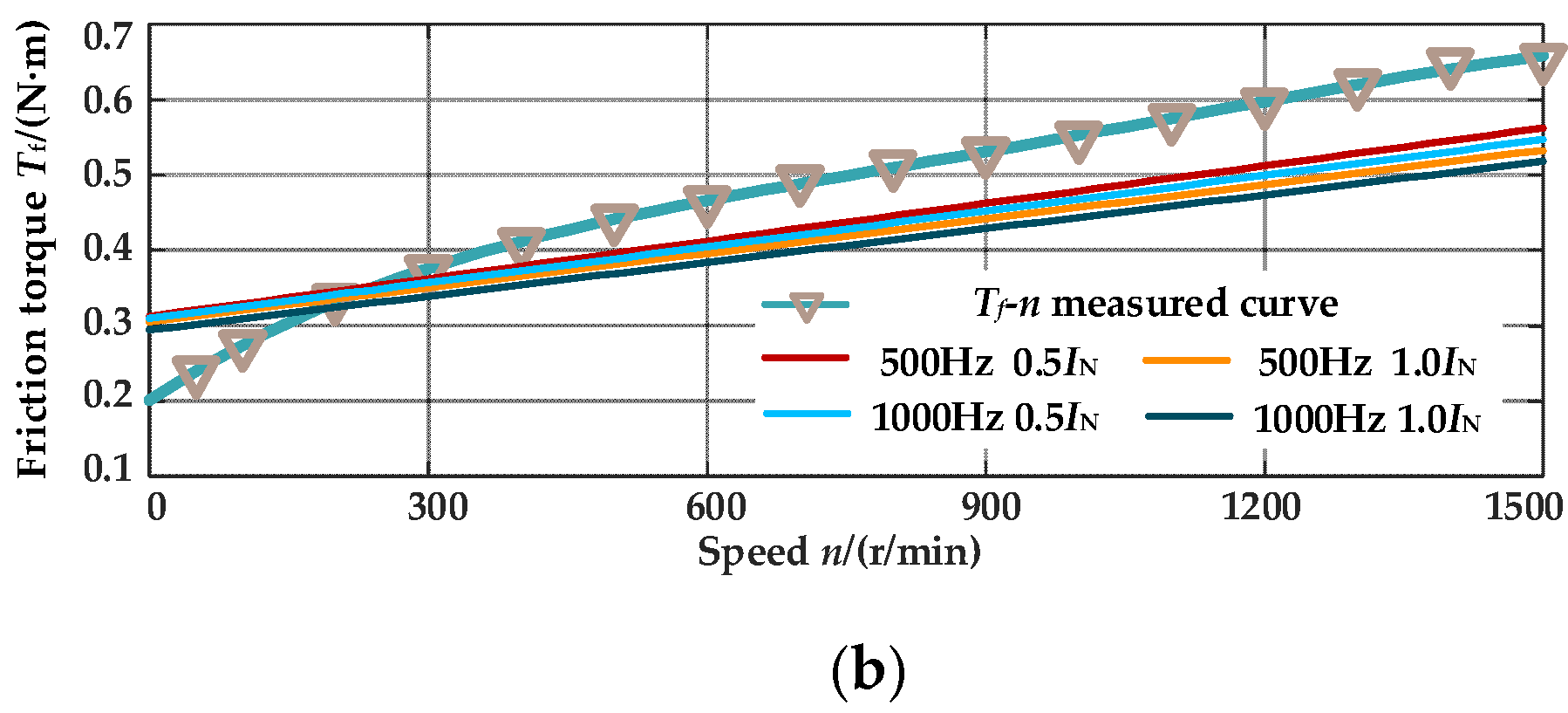

Table 1.
Related parameters of PMSM drive system.
| Parameters | Values |
|---|---|
| Direct current bus voltage Udc/V | 311 |
| Stator resistance Rs/Ω | 1.508 |
| Stator inductance Ld/mH | 6.6571 |
| Stator inductance Lq/mH | 12.8436 |
| Permanent magnet flux linkage ψf/Wb | 0.175 |
| Number of pole pairs pn | 5 |
| Rated voltage UN/V | 220 |
| Rated current IN/A | 8 |
| Rated speed n/(r/min) | 1500 |
| Moment of inertia J/(kg·m2) | 0.0023 |
| Viscous damping coefficient Bm/(N·m·s/rad) | 0.002 |
| Coulomb friction coefficient Cm/(N·m) | 0.35 |
Table 2.
Simulation Results of Electrical Parameter Identification Algorithm.
| Project | Actual Value | Identified Value | Relative Error σ |
|---|---|---|---|
| Stator Resistance Rs/Ω | 1.508 | 1.41855 | -5.93168% |
| d-axis inductance Ld/mH | 6.6571 | 6.59177 | -0.981290% |
| q-axis inductance Lq/mH | 12.8436 | 12.75555 | -0.685547% |
Table 3.
Simulation Results of Mechanical Parameter Identification Algorithm.
| Project | Actual Value | Identified Value | Relative Error σ |
|---|---|---|---|
| Magnet Flux ψf/Wb | 0.1750 | 0.176216 | 0.695069% |
| Rotational Inertia J/(kg·m2) | 0.0023 | 0.0023006 | 0.026919% |
| Viscous Damping Bm/(N·m·s/rad) | 0.0020 | 0.0019989 | -0.059131% |
| Coulomb Friction Cm/(N·m) | 0.3500 | 0.3502411 | 0.068883% |
Disclaimer/Publisher’s Note: The statements, opinions and data contained in all publications are solely those of the individual author(s) and contributor(s) and not of MDPI and/or the editor(s). MDPI and/or the editor(s) disclaim responsibility for any injury to people or property resulting from any ideas, methods, instructions or products referred to in the content. |
© 2025 by the authors. Licensee MDPI, Basel, Switzerland. This article is an open access article distributed under the terms and conditions of the Creative Commons Attribution (CC BY) license (http://creativecommons.org/licenses/by/4.0/).
Copyright: This open access article is published under a Creative Commons CC BY 4.0 license, which permit the free download, distribution, and reuse, provided that the author and preprint are cited in any reuse.


