Submitted:
03 January 2025
Posted:
03 January 2025
You are already at the latest version
Abstract
This study focuses on the restoration of large-module gear teeth for ball mills through electroslag surfacing, emphasizing practical results and mathematical modeling. The research explores wear mechanisms, restoration processes, and laboratory experiments to evaluate the hardness and surface roughness of restored teeth. Optimal surfacing modes were identified, including key parameters such as current strength, slag bath voltage, and cooling water flow rate. These parameters ensure the durability and operational efficiency of restored gears. Mathematical modeling and experimental analysis have provided equations that describe the dependencies between surfacing modes, wear resistance, and mechanical properties. The findings are highly relevant for industries engaged in gear restoration, enabling significant cost reductions and improved reliability.
Keywords:
electro-slag surfacing
; large-module gears
; planning of multifactor experiment
; roughness
; hardness
1. Introduction
Drum ball mills (DBMs) (Figure 1) [1] are used to grind anthracite, hard and brown coals, shale, and other materials into a powdered form. They are designed for continuous operation as part of the dust preparation systems in thermal power plants. These mills are installed in accordance with established standards for the calculation and design of dust preparation installations for boiler units. The grinding process is achieved through the combined impact and friction of steel balls inside the drum. The finished dust is continuously extracted through a pipe via the gas-air network.
The drum rotates from the main electric motor through couplings, gearboxes and drive gears (Figure 3). The drive system consists of a ring gear and a drive gear.
Grinding units experience the most intense abrasive wear during operation [2]. Such wear disrupts the interaction between components and assemblies, potentially leading to increased loads, joint shocks, vibrations, and even sudden failures [3]. For instance, parts of the DBM drive, such as the drive gear, are subjected to prolonged exposure to variable loads during operation. These fluctuating loads can cause significant destruction of components, often accompanied by noticeable plastic deformations. Wear, abrasion, and tooth fractures result in changes to the initial dimensions (Figure 3a) and shapes (Figure 3b).
Restoring the operability of gears is an important and complex process that can be carried out using various methods depending on the condition and nature of the gear’s damage [4,5,6,7]. For large steel gears, it is more practical to fully cut off the worn teeth on lathes [8,9], followed by automatic surfacing under a flux layer [10,11] along the outer surface [12] to the full height of the teeth [13]. The surfaced layer is then machined on a lathe, and the teeth are cut on a gear-cutting machine.
1. 1 In the course of the study, the following methods were applied: the influence of surfacing modes on the quality of the clad tooth was analyzed. The experimental approach was applied, including the use of the electro-slag surfacing method for gear teeth restoration.
1.2 The research methodology includes the following main stages: development of equipment for electro-slag surfacing, including the organization of the laboratory installation; development of the crystallizer design, ensuring compliance of the part dimensions with the drawings; surfacing of teeth on the electro-slag surfacing installation; verification of compliance of the surfaced tooth dimensions with the requirements of the drawings; mathematical modeling; data analysis; determination of tooth quality parameters; identification of regularities between quality parameters and surfacing modes.
1.3 The problem of the research lies in the insufficient study of the influence of different modes of electro-slag surfacing on the quality of teeth of large-modular gears, which complicates the optimal restoration methods development. It should be taken into account that previous works did not provide sufficient data for system analysis, which creates difficulties in the choice of surface parameters and reduces the efficiency of production processes. This work aims to address these gaps by organizing thorough experiments and analyzing the collected data.
1.4 The aim is to investigate the influence of surfacing modes on the roughness and hardness of the clad tooth, as well as to determine the optimum conditions of electro-slag surfacing, which provides the best combination of surface quality and mechanical properties.
2. Description of the Experimental Setup and Operating Modes
Laboratory installation for electro-slag surfacing (Figure 4) consists of welding tractor ADF-1005 Ural, crystallizer (4) with connections (7 and 8), and water meter for water consumption control. Electroslag surfacing begins with the supply of electric current from the power source 6, after which the necessary parameters of the operating mode are set from the control panel (1). Welding wire (3) of 3mm diameter of 30 steel HGSA, fed from the cassette, passes through the mouthpiece. The mouthpiece is used when the volume of the weld metal is greater than 10mm3 [14,15]. The material of the mouthpiece is selected according to the recovered wheel diameter of 6mm, with material St3. The gap between the fusion zone and the center of the welding wire is 25mm. The crystallizer (4) is fixed using a special clamp. In the working area of the crystallizer from a container (5) is fed flux OX Flux 10.71 to ensure the cladding process. After preparing the device, the melting process is started by pressing the “Start” button on the control panel. The electroslag surfacing of the gear teeth is initiated (Figure 5). Technical characteristics of the welding tractor are given in Table 1.
The surfacing current strength was determined based on the technical specifications of the ADF-1005 ’Ural’ welding machine. The current values were set depending on the module of the surfaced tooth and the length of the crystallizer. Optimal current values were established experimentally. The current strength was controlled via the welding machine’s control panel, where the required parameters were set, and during the experiment, the values were monitored visually.
Slag bath stress [16] is a determining factor in electro-slag surfacing, affecting both the stability of the process and the amount of penetration [17] of the base metal [18,19]. The formula [16] was used to calculate the stresses in the slag bath:
where m - module of the cladding tooth, mm.
I - current intensity, A.
In the electro-slag surfacing process, the crystallizer [20] is used to form the clad metal by the specified shape. The greatest importance for ensuring the stability of the electro-slag process and the high quality of the welded and base metal joint is a stabilization of slag bath temperature [21]. For this purpose, it is necessary that the amount of heat released in the slag bath and given off by it is equal (Figure 6). Violation of the balance of heat supply and consumption can lead to overcooling of the slag bath and its boiling, which sharply reduces the amount of heat used for the melting of electrode and base metals.
To control the cooling water flow rate in the experiment we used a water meter “Proteus-15C”, with a division value of 0.001m³, installed in the sanitary room of the laboratory (Figure 7). To ensure water supply to the crystallizer from the meter were connected hoses: one for water supply, the second for its drainage (see Figure 7). This scheme of water supply allowed to effectively regulate the amount of cooling water, which provided maintenance of stable temperature of the slag bath.
During the experiment, the meter readings were stable, which contributed to uniform cooling and a stable overlay process.
3. Methods and Instruments for Measuring Roughness and Hardness
3.1. Determination of Roughness Parameters
According to [22] surface roughness is evaluated by one of the following parameters: Ra - arithmetic mean deviation of the profile; Rz – the height of irregularities of the profile at ten points; Rmah - the highest height of the profile. This study considers the arithmetic mean deviation of the profile - Ra. The length of the section used to assess roughness is called the base length, it was taken for the dividing diameter within 0.8mm, and for the top of the tooth - 8mm by the roughness of the working drawing of the gear [23].
Determination of roughness parameters was carried out in a portable meter TR 220 (Figure 8), the measuring range of the sensor needle was ±80 microns, and visually by comparing the surface with roughness standards. The meter calculates roughness parameters and displays all measured parameters on the LCD screen. The surface roughness was evaluated in the direction that gives the highest roughness after EAF, namely in the direction of the slagging process. When evaluating the surface roughness of the teeth surface, both longitudinal (along the tooth) and transverse (along the tooth height) directions were measured (Figure 9). For reliable roughness evaluation taking into account the registration of the device readings, the roughness parameters were determined at the base areas and the arithmetic mean value was taken as the measurement result.
3.2. Determination of Tooth Surface Hardness
Hardness was measured by the Rockwell method at temperature +200C (Figure 10), hardness tester Mitutoyo HV-100 at a depth of 0.2 mm with a diamond tip [24]. In the course of hardness measurement, measurements were made both on the working surfaces of the tooth and in its middle part. Within the framework of mathematical planning, the hardness values of the working surfaces of the tooth (B) were taken into account, and the hardness of the top and middle part (A) served as an indicator for controlling the stability of the surfacing process (Figure 11).
4. Mathematical Modeling
4.1. Planning and Conditions for Conducting a Multifactor Experiment
The qualitative parameters of the clad tooth are affected to a greater or lesser extent by a large number of factors in the surfacing process. According to the methodology given in [25], a combined square for a three-factor complex was constructed. The intervals of variation of the factors were chosen by experiments in such a way that monotonic changes in the studied indicators of the quality of the clad tooth surface were obtained within these limits. The design of the three-factor experiment at five levels is shown in Table 2.
The need for a method of rational planning of experiments arises when one has to deal with a large number of influencing factors since it is almost impossible to test all possible combinations of these factors on experience due to the huge number of such combinations.
The following parameters of the clad coarse-modular tooth were investigated:
- Y1 – the roughness of the clad tooth Ra, microns;
-Y2 - hardness of the tooth according to Rockwell HRC.
Based on the experiments conducted with the modes given in the plan, the following specimens of 30CrHSSA steel were obtained. (Figure 12).
4.2. Processing of Multifactorial Experiment Results
The results of the multivariate experiment were processed using the “Anetr-5” program [25]. The method is universal, both in terms of application area and in the variants of model construction: models can take the form of sum, product of partial dependencies, and their combinations, with consistent neutralization of the influence of those arguments, which in traditional methods will be excluded from the analysis as not affecting the target function significantly according to the Fisher criterion.
The method is deterministic, i.e., it allows to limit the choice of the model by known data on the theory of the process (type of equation, limits, etc.). at the output, the program, besides the analytical character of the partial relations, gives their graphs, and reliability estimation, ranks the factors by the strength of interaction on the results, and allows to single out significantly influencing factors.
The program finds partial relationships among fifteen equations, each of which is assigned a serial number:
- Y=A+BX;
- Y=A+B lgX;
- Y= A+B/X;
- Y=AxB;
- Y= AeBX;
- Y= X/(A+BX);
- Y= 1/(A+BX);
- Y= AXB +C;
- Y= AeBX +C;
- Y= (C+DX)/(A+BX);
- Y= AX2 +BX+C;
- Y= AeXp (BeCX);
- Y= AeXp (BXC);
- Y= AXB eCX;
- Y= AeBX +C eDX.
Changing the parameter p in the program, which can take the values p=0, p=1, p=2, p=3, p=4, will allow us to obtain different types of generalized formulas both with neutralization of arguments (by the smallest RMS) and without neutralization.
Formulas of the obtained models and types of generalized equations of clad tooth quality parameters are presented below:
- Y1= АеBX2
- Y1= A+BX3;
- Y1= AX1 2 +BX1+C;
- Y1= Y(Х3) + Y(Х2) Y(Х1);
- Y2= A+B/X1;
- Y2=A+BX3;
- Y2= А Х22 + BX2+C;
We evaluate the degree of adequacy of the found models to the initial data through RMS:
where Үe – an experimental value of the function (quality parameter of the clad tooth);
- Үr - calculated value of the function;
- - average value of the function;
- N - number of experiments.
At each stage, in addition to the RMS between the initial data and the calculated data, the multiple correlation coefficient R and Fisher’s criterion F are calculated.
According to the literature [26], the model is considered excellent if the RMS is less than 20% and good if the RMSD is between 20% and 50%.
Taking into account the types of generalized equations and equation coefficients, we obtain the following dependencies linking the modes of surfacing parameters with the quality of the clad tooth:
1. Y1 – the roughness of the clad tooth Ra, µm
RMSD = 35.68%. Multiple correlation coefficient: R=0.924.
The calculated Fisher’s criterion F = 7.82749 is obtained greater than that for 1% significance level F (001) = 2.63605 and for 5% F (005) = 1.97744.
2. Y2 – hardness of the tooth according to Rockwell HRC.
RMSD % = 34.34%. Multiple correlation coefficient: R=0.903.
The calculated Fisher’s criterion F=8.47896 is greater than for 1% significance level F (001) =2.63605 and for 5% significance level F (005) = 1.97744
The obtained mathematical models, linking the quality of the clad tooth with cladding modes, allow for control of the quality parameters of the clad tooth, providing high parameters and operational properties of the gear.
5. Results and Discussion
Data analysis. We reveal regularities and dependencies between roughness parameters (Figure 13) and the hardness of the clad tooth from the cladding mode (Figure 14).
In electro-slag surfacing (Figure 15), a perfectly smooth surfacing surface cannot be obtained; it is more similar to the surface of a casting (Figure 16). In improving the tooth surfacing technology, the authors aimed to achieve minimal surface roughness.
During electro-slag surfacing, heat is generated intensively. The water in the cooling system helps to dissipate this heat. If the water flow rate is reduced to optimum levels, cooling is sufficiently fast to reduce the chance of rough surface finishes. However, if the flow rate is reduced too much (less than 3 l/min), the cooling is insufficient to maintain a stable temperature in the surfacing zone, resulting in overheating and poor surface finish. When the metal is overheated due to insufficient cooling, the microstructure of the cladding layer changes. In this undesirable structural changes such as grain enlargement, pore formation, and cracking are observed. This can also deteriorate the surface properties and its roughness. During experimental studies, it was observed that every time the crystallizer cooling is increased up to 4.5l/min it leads to a rough surface defect in the form of ducking or corrugation (Figure 17).
Increasing the welding current (up to 400A) leads to an increase in the roughness height and hardness in the middle part of the clad tooth (4 samples).
With increasing slag bath voltage, a decrease in roughness parameters is observed (Figure 13). This phenomenon is related to the fact that increasing slag bath temperature leads to thinning of garnish crust and improvement of its forming properties. The pitch and height of roughnesses decrease as the water flow rate decreases (3 - 3.5 l/min). The change in water flow rate in the cooling system is related to heat generation and cooling of the clad metal. At insufficient cooling in the maximum current value, the material undergoes additional thermal deformations. Inhomogeneous shrinkage (#1, 2, 3, 5) and thermal stress arise, which leads to the formation of irregularities and deterioration of surface characteristics (Figure 17).
After establishing optimal surfacing modes, the gear teeth of a ball drum mill were successfully restored (Figure 18).
6. Conclusions
The optimal surfacing mode is characterized by complete process stability, eliminating short-term disruptions. This is achieved by stabilizing electrical and technological parameters (current strength, slag bath voltage) and processing a significant amount of experimental data. As a result, high-quality surfacing of the gear tooth is ensured, with a surface roughness of Ra 7.5-9 μm and hardness of 34-36 HRC. The following surfacing parameters are recommended:
- Current strength, I = 362.5 A.
- Slag bath voltage, U = 73.25-74 V.
- Water flow rate, Q = 3-3.5 l/min.
As a result of the conducted research, it has been established that optimal modes of electroslag surfacing are achieved by stabilizing key process parameters (current strength, slag bath voltage, and water flow rate). These parameters ensure high-quality surfacing of gear teeth with minimal surface roughness and the required hardness.
It was revealed that the stabilization of electrical and technological parameters, such as current strength and slag bath voltage, allows for the elimination of short-term process interruptions. This, in turn, contributes to the formation of a smoother and more stable surface with a roughness of Ra 7,5-9 μm, meeting high surface quality standards for gear teeth.
The established surfacing modes (I = 362.5 A; U = 73.25-74 V; Q = 3-3.5 l/min) ensure not only optimal heat dissipation and uniform cooling but also help prevent overheating and structural defects such as pores, cracks, and grain enlargement, which could negatively affect the wear resistance and durability of the teeth.
It was experimentally confirmed that increasing the current strength to 400 A and above leads to increased thermal deformations and surface defects such as wrinkling and shrinkage. This highlights the importance of maintaining current strength within the range of 362.5-375 A to ensure a high-quality result.
The practical significance of this research lies in the development of recommendations for electroslag surfacing modes that can be applied in production to enhance the durability and reliability of restored gear teeth, while minimizing additional machining costs.
Declaration of Interests
The authors declare that there are no conflicts of interest regarding the publication of this paper. The research was conducted independently, with no financial or personal relationships with other people or organizations that could have influenced the work reported in this paper.
References
- Available online:. Available online: https://library.e.abb.com/public/25ce82cc89a14c85a862dd840abcdff8/Ring_geared_mill_drives_LR_web.pdf (accessed on 24 February 2024).
- B13—Gear failures. Lubrication and Reliability Handbook 2001. [CrossRef]
- Onishchenko, V. Investigation of tooth wear from scuffing of heavy-duty machine spur gears. Mech. Mach. Theory 2015, 83, 38–45. [Google Scholar] [CrossRef]
- Kozulin, S.M.; Lychko, I.I. Electroslag Surfacing of Large-Module Gear Teeth. Autom. Weld. 1987, 3, 62–64. [Google Scholar]
- Kozulin, S.M.; Lychko, I.I.; Kozulin, V.M.; Bordovsky, A.P. Device for Electroslag Surfacing of Large-Module Gear Teeth. Autom. Weld. 1987, 11, 74–75. [Google Scholar]
- Rosenberg, O.O.; Muzychenko, K.K.; Malkin, L.S. Restoration of Chevron Gear Teeth of Unique Gears in Crank-Tube Presses by Electroslag Surfacing. Automatic Welding 1966, 11, 53–65. [Google Scholar]
- Smailova, B.K.; Buzauova, T.M.; Bartenev, I.A.; Davletova, K. Restoration of Large Modular Teeth of Ball Mill Gears by Electro-Slag Surfacing. J. Appl. Eng. Sci. 2024, 22, 483–491. [Google Scholar] [CrossRef]
- Kozulin, S.M.; Sushchuk-Slyusarenko, I.I.; Lychko, I.I. Influence of Electroslag Surfacing Parameters on the Quality of Restored Gear Teeth. Automatic Welding 2006, 9, 57–60. [Google Scholar]
- Ryabtsev, I.; et al. Electroslag Surfacing. In Surfacing and Additive Technologies in Welded Fabrication; Springer Nature: Cham, Switzerland, 2023; Volume 11, pp. 83–107. [Google Scholar]
- Kuskov, Y.M.; Evdokimov, A.I. Electroslag Surfacing of Wear-Resistant Alloyed Cast Irons. Strengthening Technologies and Coatings 2014, 10, 21–24. [Google Scholar]
- Ksenzdyk, G.V.; Kuskov, Y.M.; Sery, V.N. Selection of Flux for Electroslag Surfacing with Steel Shot. Automatic Welding 1993, 12, 48–49. [Google Scholar]
- Kozulin, S.M.; Lychko, I.I.; Podyma, G.S. Electroslag Surfacing of Gear Shaft Teeth of Rotary Kilns. Automatic Welding 2008, 4, 24–30. [Google Scholar]
- Sushchuk-Slyusarenko, I.I.; Lychko, I.I.; Kozulin, M.G.; Semenov, V.M. Electroslag Welding and Surfacing in Repair Work. Kyiv: Naukova, Dumka, 1989; p. 192.
- Oleynichenko, V.I.; Vishnevsky, A.V. Electroslag Surfacing with a Tubular Electrode. Information Bulletin, 1975; -75. [Google Scholar]
- Shvartser, A.Y.; Stoiko, V.P.; Nikitienko, Z.L.; Morgachev, I.G. Restoration of Excavator Bucket Teeth with Variable Surfaced Metal Composition. Automatic Welding 1985, 3, 46–48. [Google Scholar]
- Patent, No. 1149518A. “Method for Restoring Large-Module Gear Teeth.” V.A. Danilov, V.I. Bochenin, A.N. Davidovsky, I.A. Bartenev. , 1984. 23 August.
- Bondarenko, O.P.; Lychko, I.I.; Popovsky, V.Y. , et al. Stabilization of Chemical Composition of the Slag Bath in Electroslag Welding of Extended Seams. Automatic Welding 1986, 54–56. [Google Scholar]
- Smailova, B.K.; Buzauova, T.M.; Bartenev, I.A.; Sarbayev, D.A.; Škamat, J. Planning and Experimental Studies of Electroslag Surfacing Mode on Penetration Depth of Welded Teeth. Science and Technology of Kazakhstan 2024, 3, 95–107. [Google Scholar] [CrossRef]
- Puzrin, L.G.; Gorodetsky, A.S. Stabilization of Base Metal Penetration in Electroslag Surfacing with a Stationary Electrode. In Problems of Electroslag Technology; Kyiv: Naukova Dumka, 1978; pp. 62–66. [Google Scholar]
- Utility. Model Patent “Crystallizer for Electroslag Surfacing of Large-Module Teeth” No. 9186, May 31, 2024, Buzauova T.M., Smailova B.K, Bartenev.
- DDudko, A.; Shcherbina, N.Y.; Sushchuk-Slyusarenko, I.I.; Khrundzhe, V.M. Method for Regulating Bath Temperature in Electroslag Surfacing. Automatic Welding 1970, 9, 45–48. [Google Scholar]
- GOST 2789-73 (ST SEV 638-77). Surface Roughness. Parameters and Characteristics. Moscow: Standards Publishing, 2024, 10 pp.
- Method for Measuring Surface Roughness Parameters According to GOST 2789-73. Using Profile Method Instruments MI41-75. Moscow: Standards Publishing, 1975, 15 pp.
- GOST 9013-59 (ISO 6508-86) Metals. Rockwell Hardness Test Method. Moscow: Standards Publishing, 2001, 10 pp.
- Ermekov, M.A.; Makhov, A.A. Statistical-Deterministic Method for Constructing Multidimensional Models Using Computers: Study Guide. Karaganda, KPTI, 1988, 70 pp.
- Malyshev, V.P. Probabilistic-Deterministic Experimental Planning. Almaty: Science, 1981, 116 pp.
Figure 1.
Ball drum mills (scale 1:1000) [1].
Figure 1.
Ball drum mills (scale 1:1000) [1].
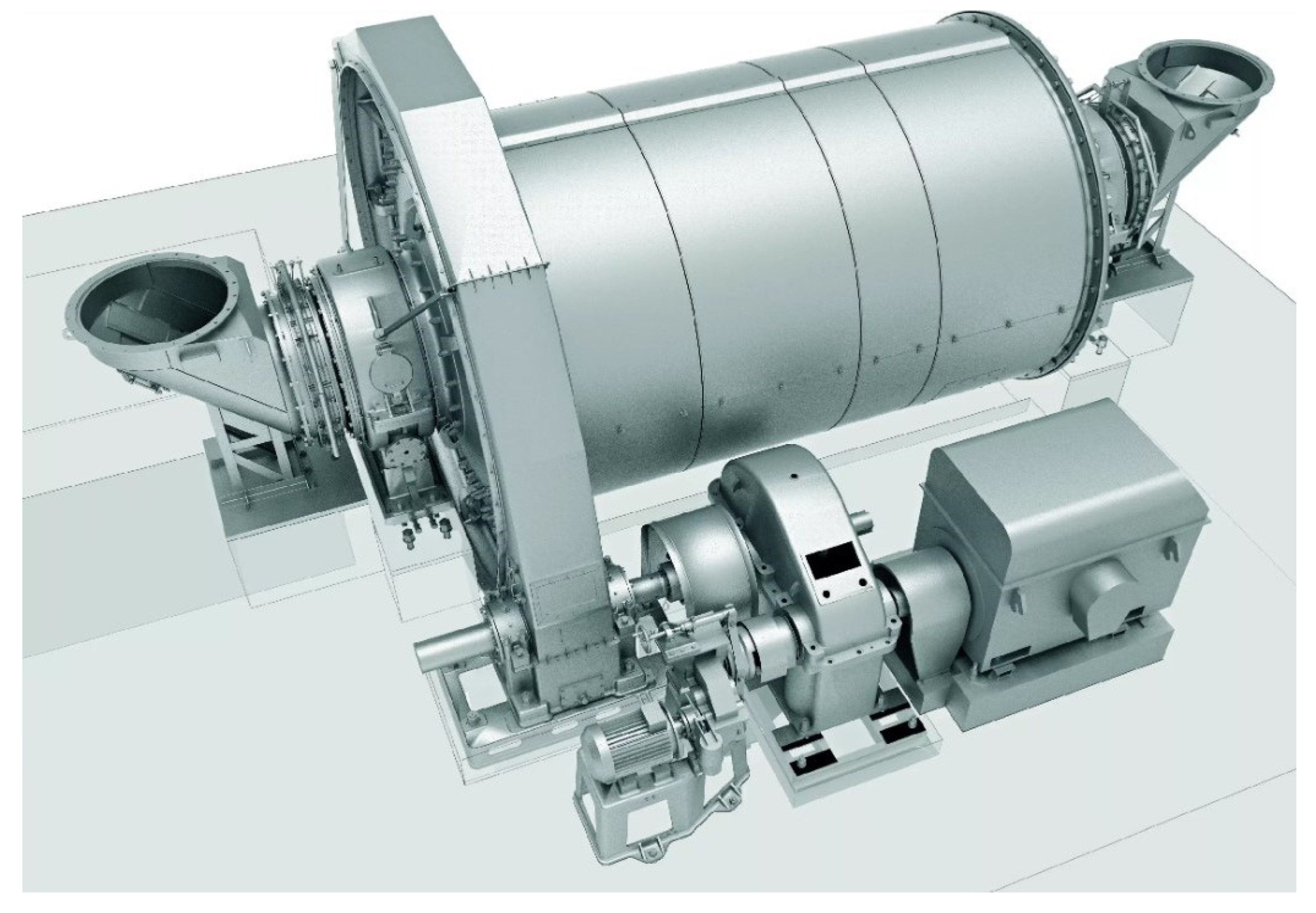
Figure 2.
Ball drum mill drive (scale 1:1000) [1].
Figure 2.
Ball drum mill drive (scale 1:1000) [1].
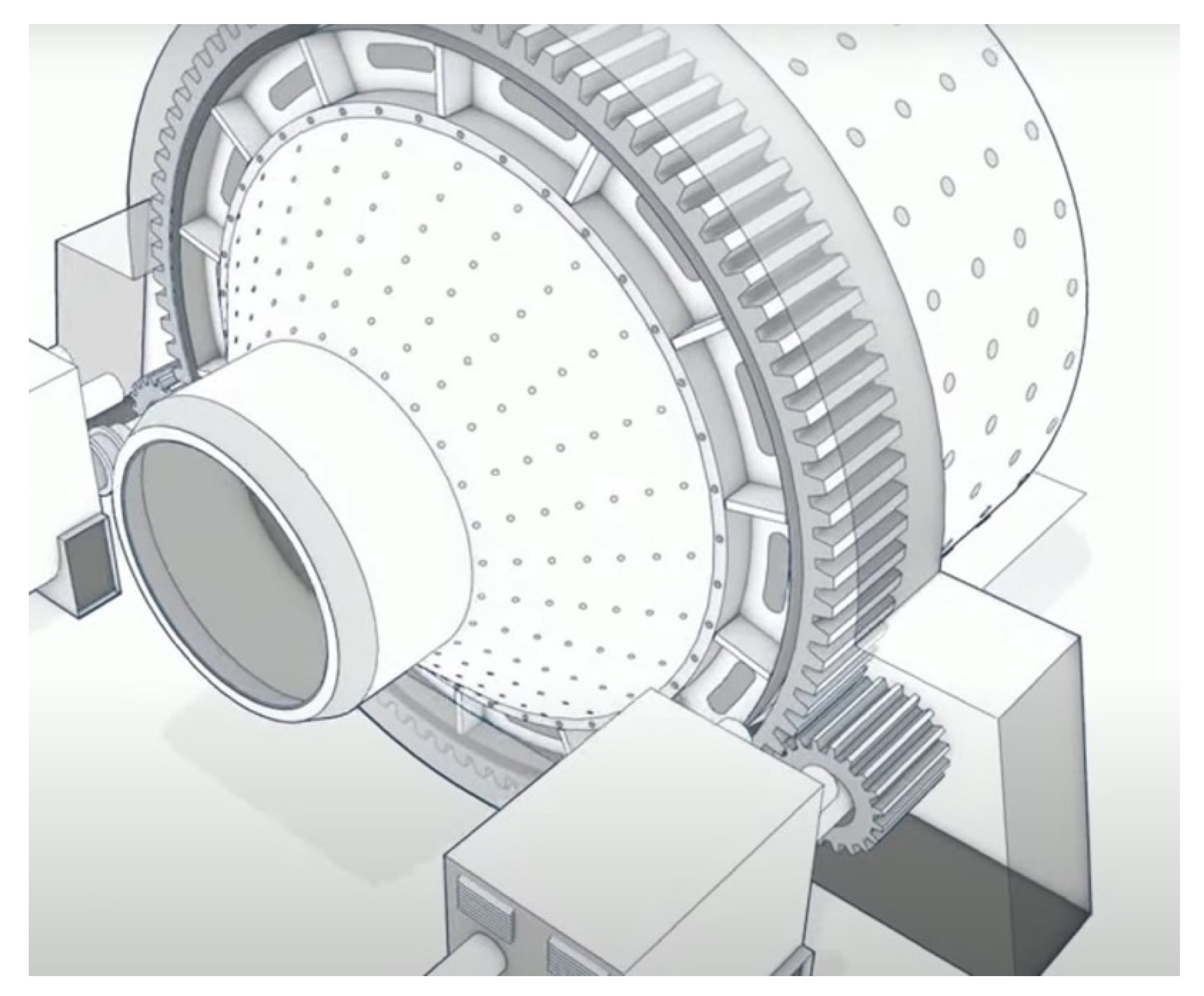
Figure 3.
Types of Wear on the Gear Teeth of a Ball Drum Mill.
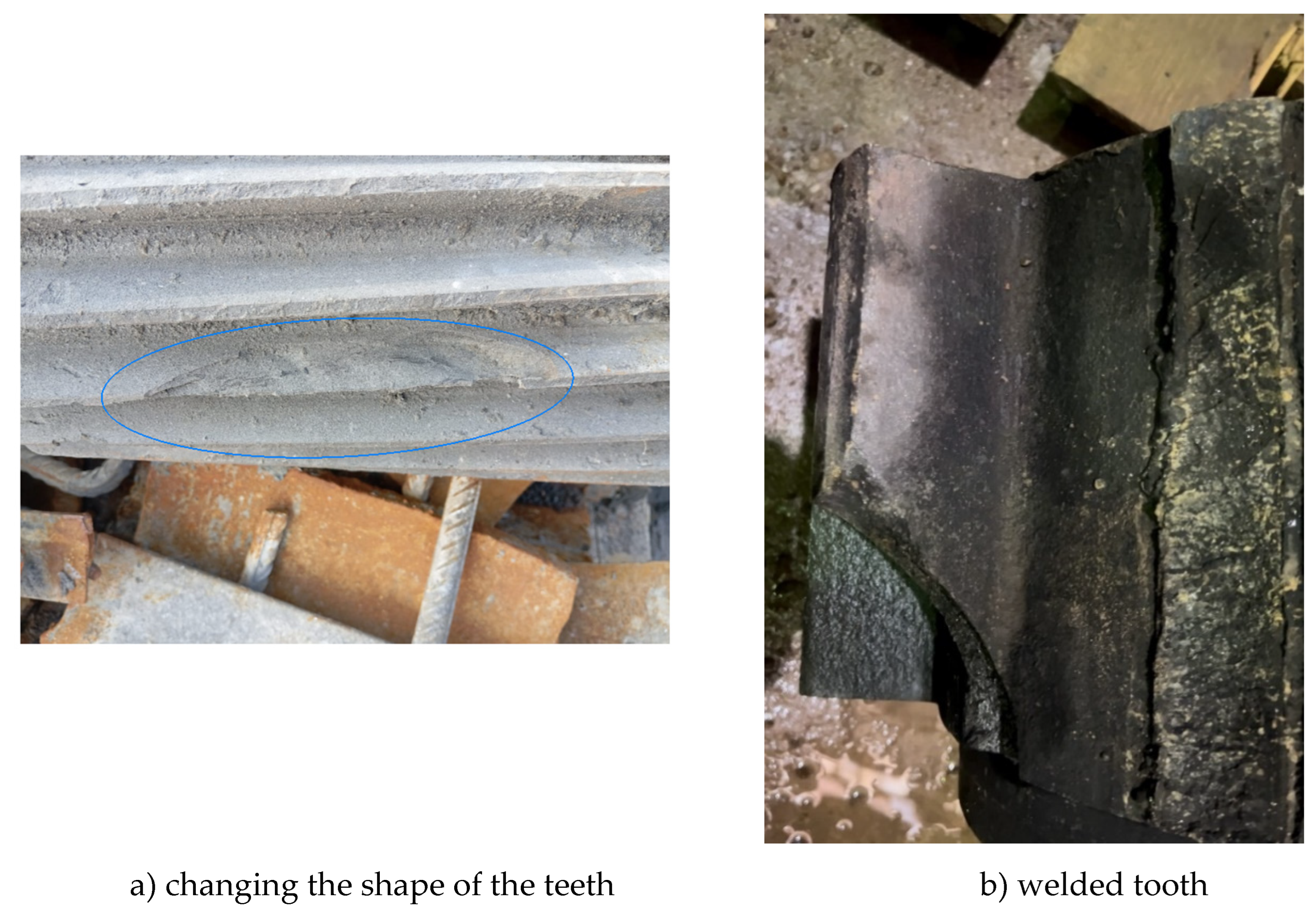
Figure 4.
Laboratory installation for electro-slag surfacing of large-module tooth samples: 1-control panel; 2-bracket for height adjustment; 3-surfacing wire; 4-crystallizer; 5-flux container; 6-power source; 7-connector for water hose connection; 8-connector for water supply.
Figure 4.
Laboratory installation for electro-slag surfacing of large-module tooth samples: 1-control panel; 2-bracket for height adjustment; 3-surfacing wire; 4-crystallizer; 5-flux container; 6-power source; 7-connector for water hose connection; 8-connector for water supply.
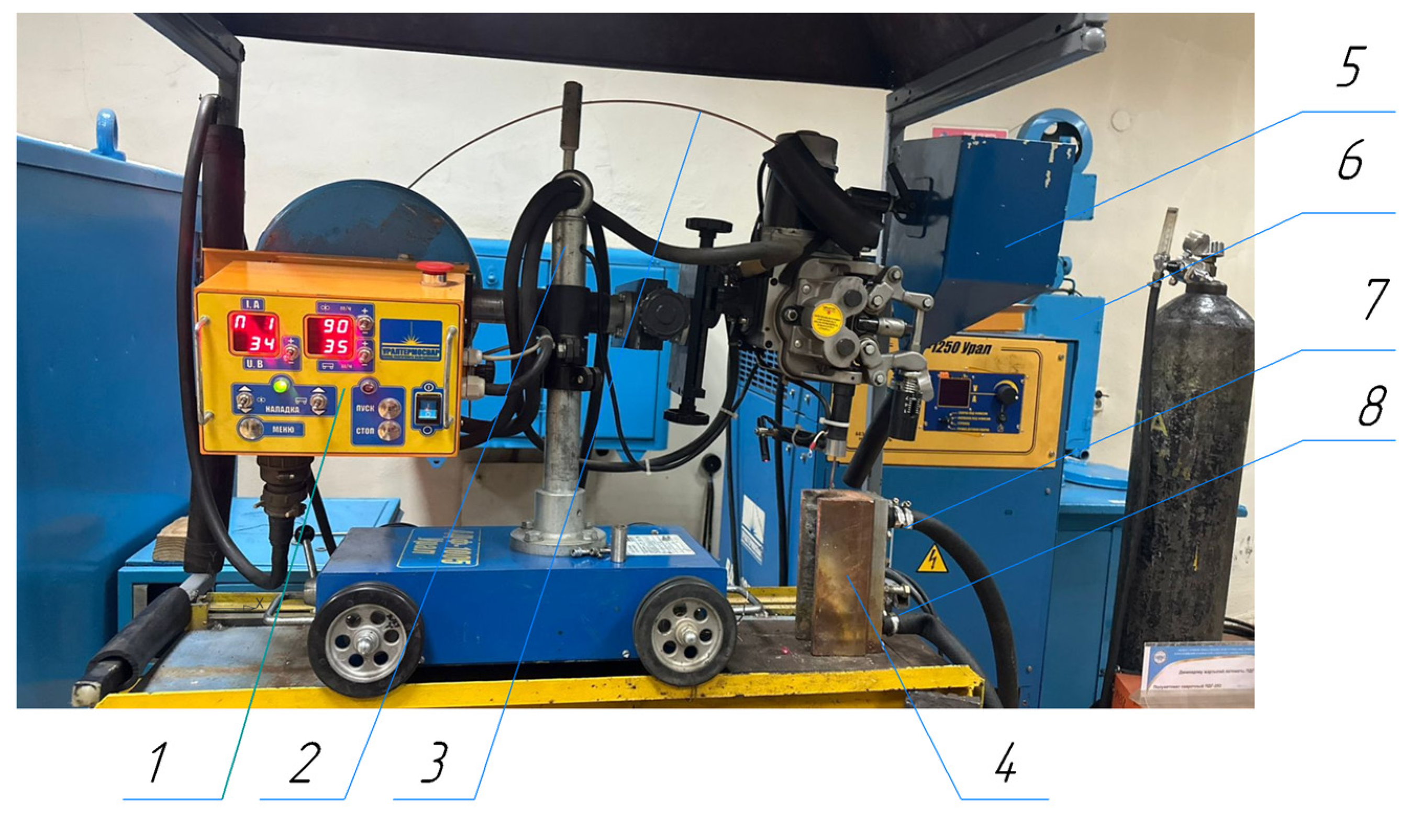
Figure 5.
Diagram of the electroslag process: 1 – plate for tooth surfacing; 2 – crystallizer with a cooling channel; 3 – crystallizer cover; 4, 5 – cooling fittings; 6 – screws for securing the cover; 7 – wire; 8 – nozzle.
Figure 5.
Diagram of the electroslag process: 1 – plate for tooth surfacing; 2 – crystallizer with a cooling channel; 3 – crystallizer cover; 4, 5 – cooling fittings; 6 – screws for securing the cover; 7 – wire; 8 – nozzle.
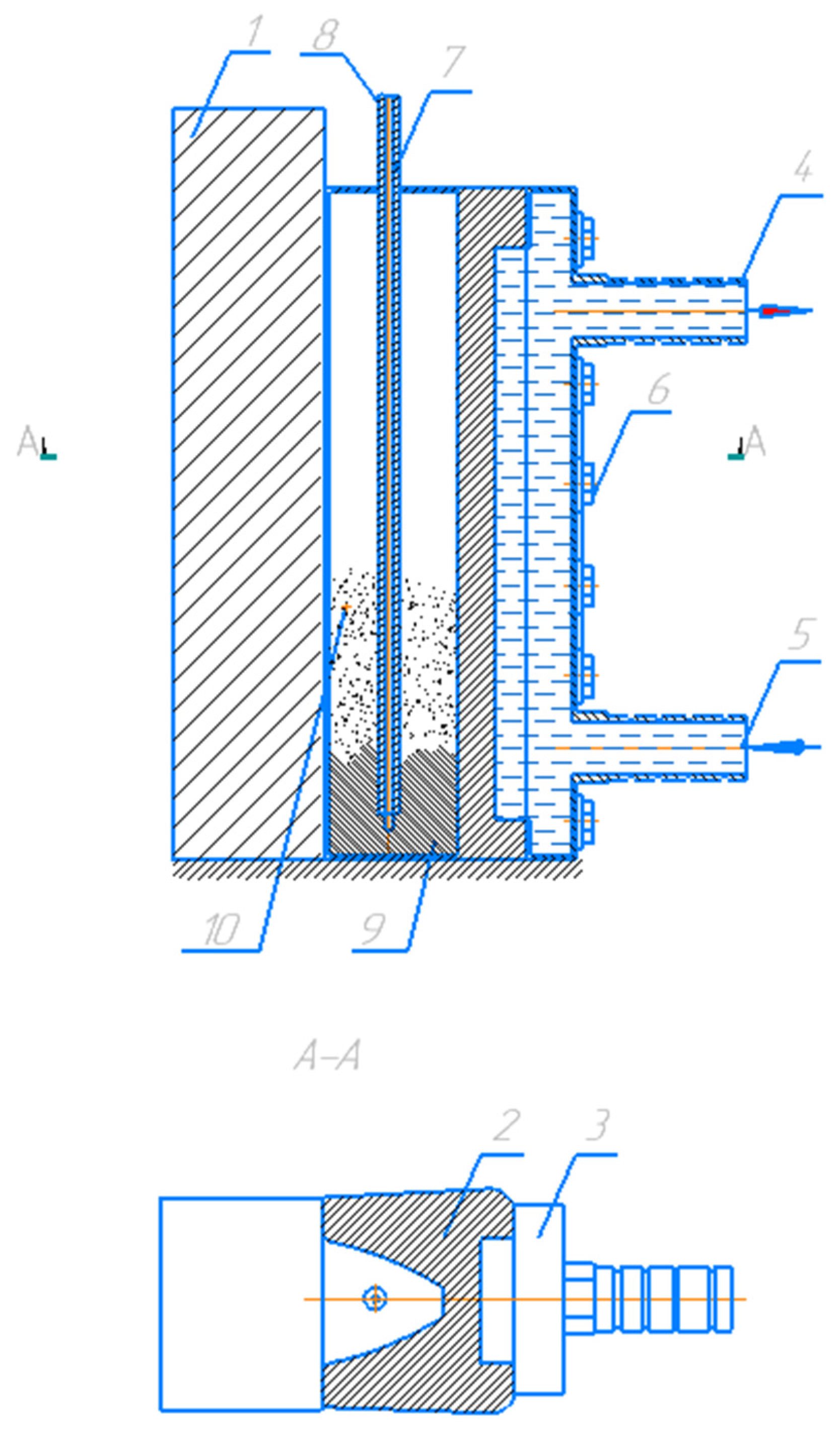
Figure 6.
Crystallizer Cooling Diagram: 1 – valve; 2 – water meter; 3, 7 – hose connection fittings; 4 – cooling channels in the cover and crystallizer; 5 – crystallizer; 6 – cover; 8 – water temperature control sensor.
Figure 6.
Crystallizer Cooling Diagram: 1 – valve; 2 – water meter; 3, 7 – hose connection fittings; 4 – cooling channels in the cover and crystallizer; 5 – crystallizer; 6 – cover; 8 – water temperature control sensor.
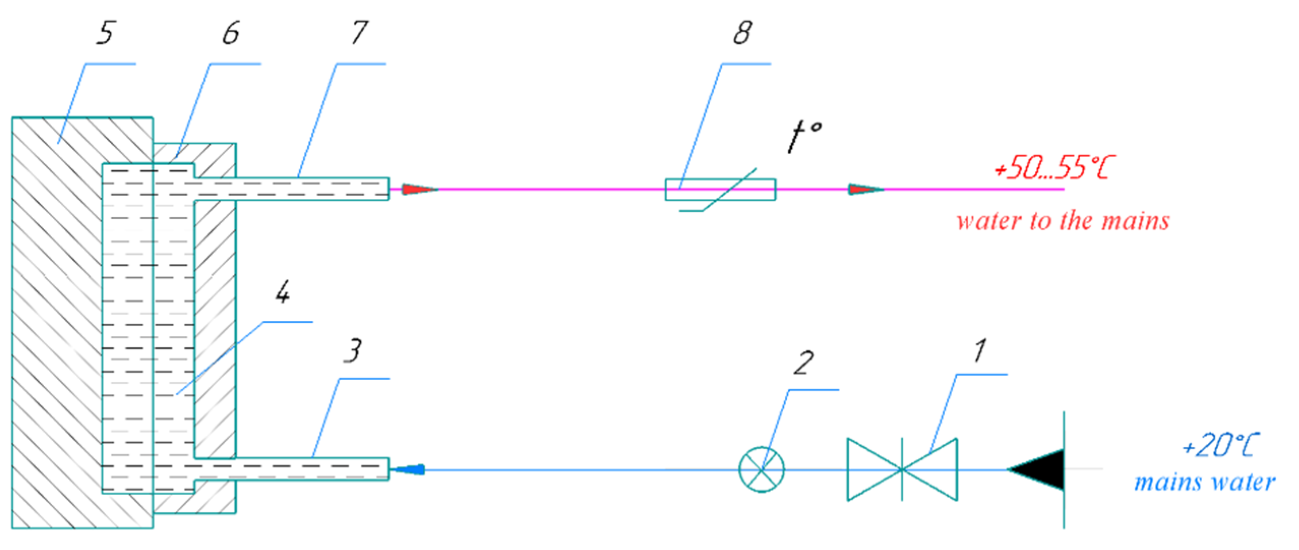
Figure 7.
Water Consumption Control Meter (1- electronic display of the meter; 2 – seal).
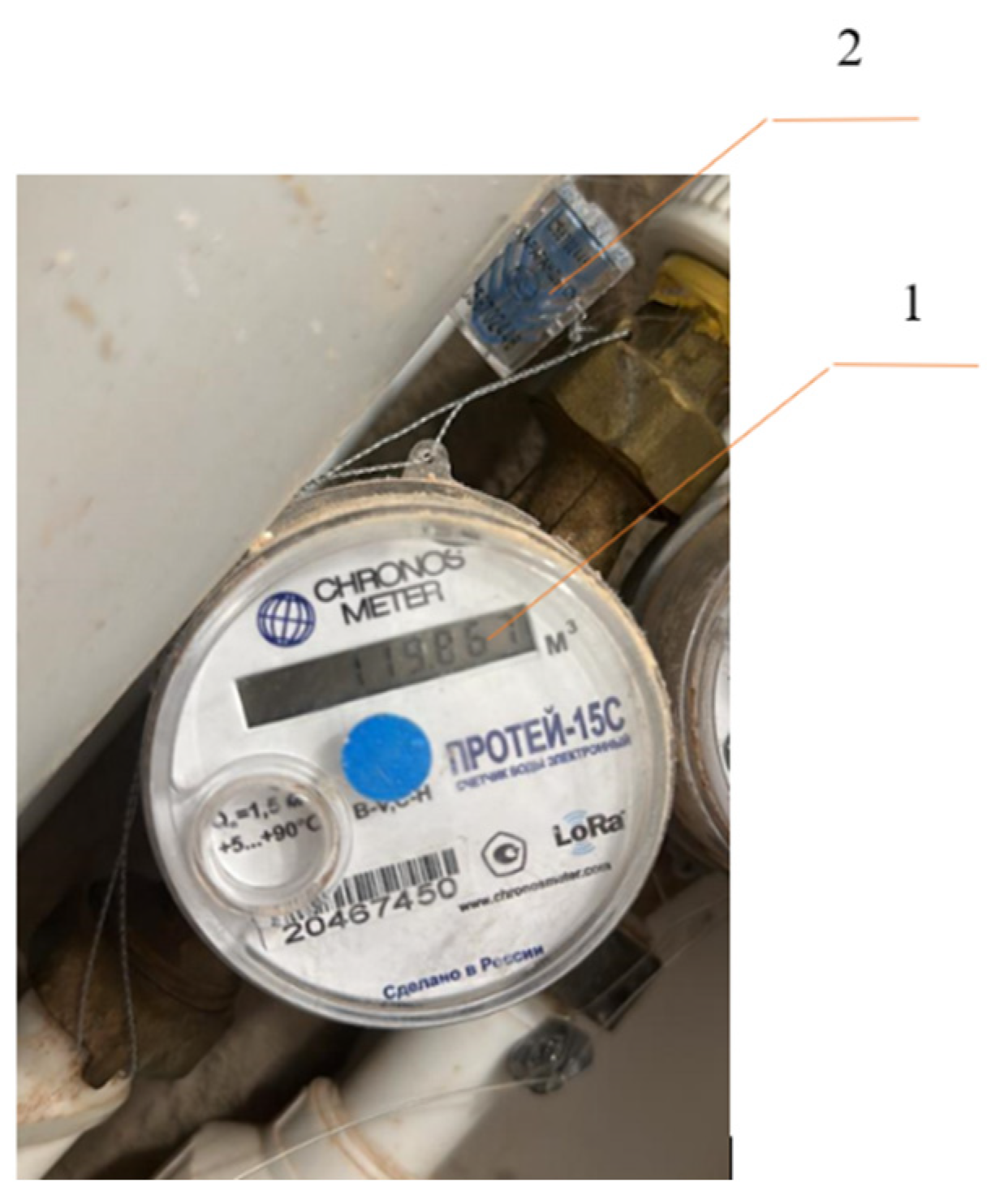
Figure 8.
Tooth sample roughness measurement process.
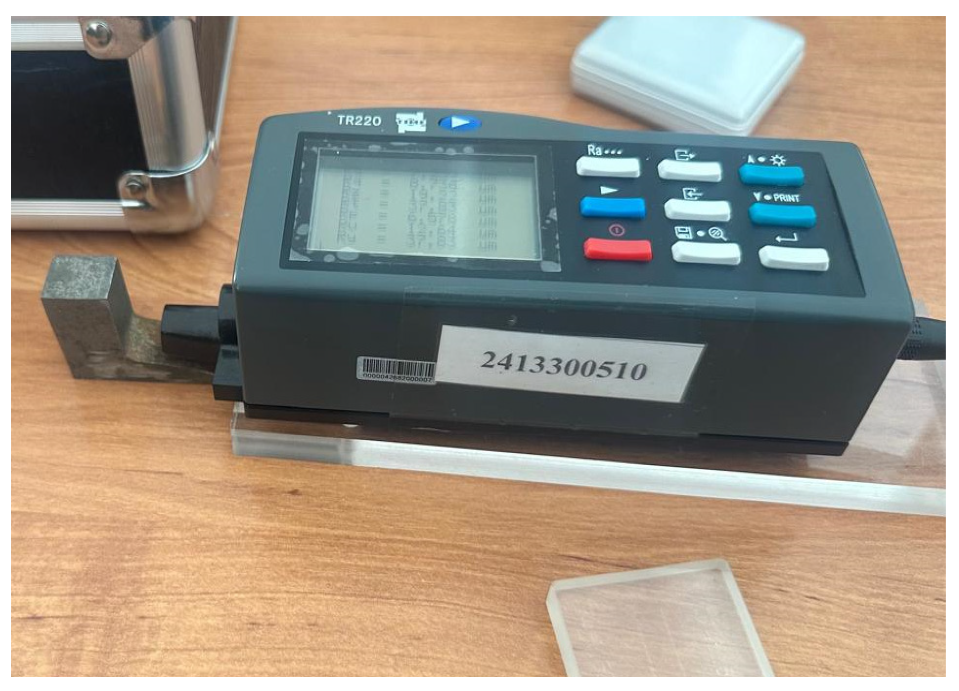
Figure 9.
Schematic of tooth surface roughness measurement: i - longitudinal direction of tooth; j - transverse direction of tooth profile.
Figure 9.
Schematic of tooth surface roughness measurement: i - longitudinal direction of tooth; j - transverse direction of tooth profile.
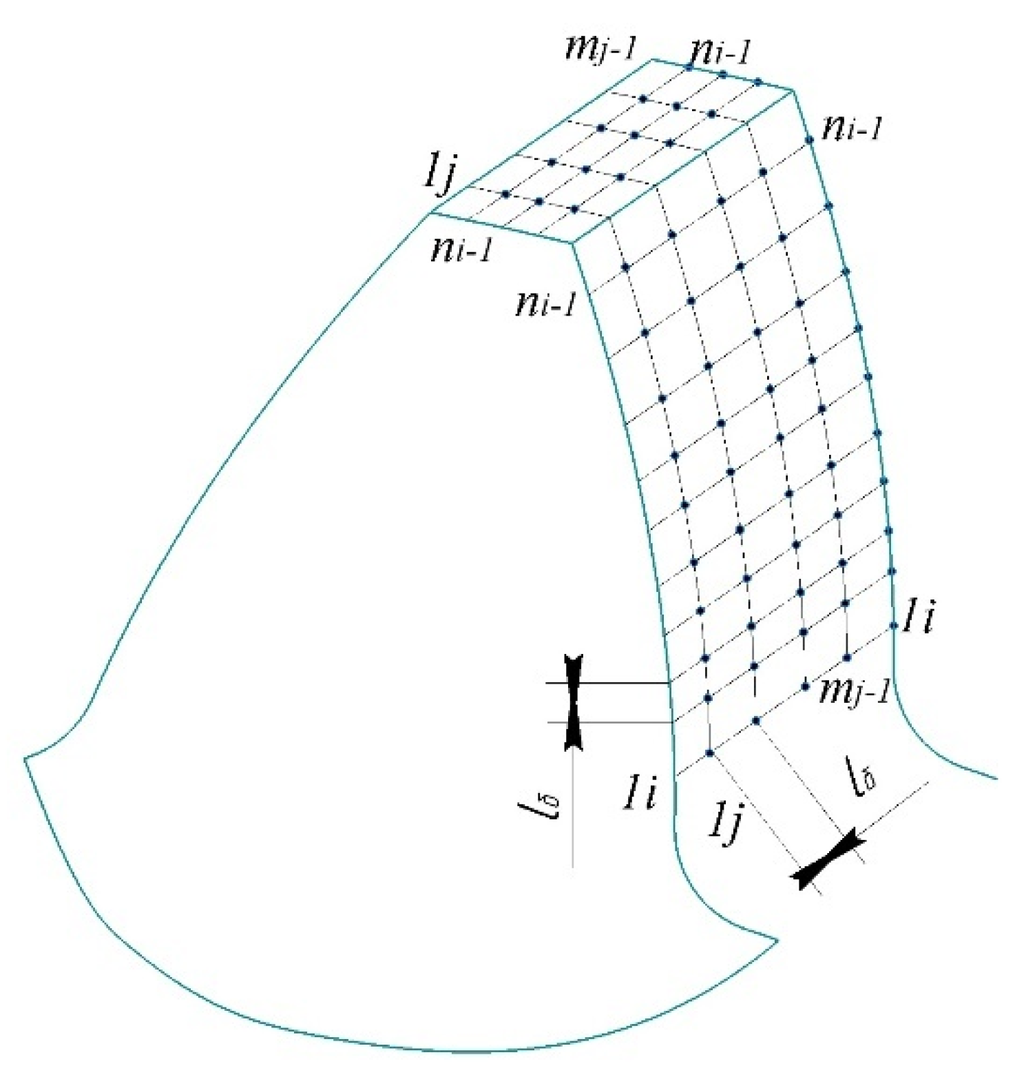
Figure 10.
Mitutoyo hardness tester.
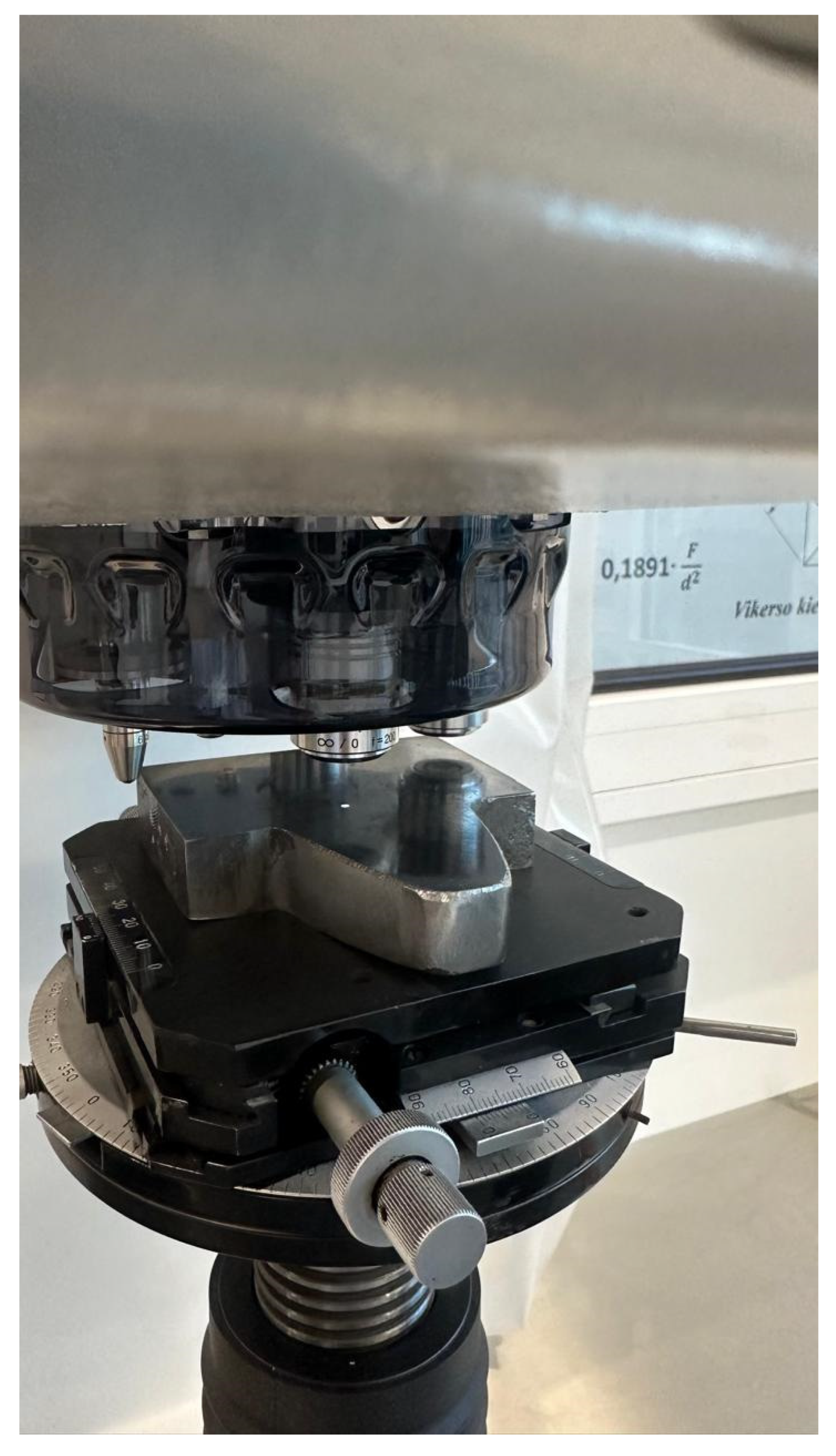
Figure 11.
Tooth hardness measurement scheme: d- dividing diameter.
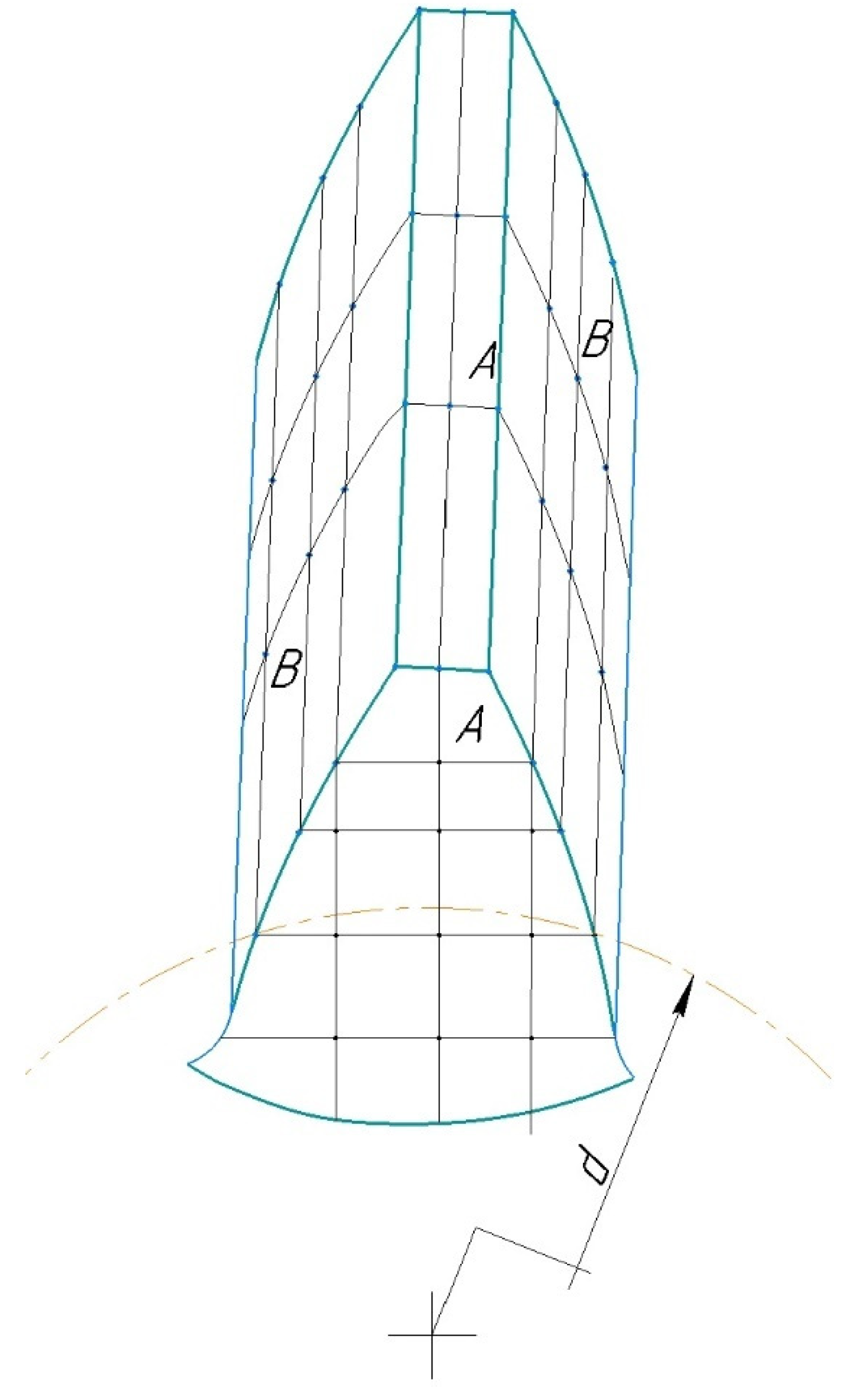
Figure 12.
Clad tooth samples with a modulus of 20mm made of 30CrHSA steel obtained at different cladding modes (the most typical results from 25 experiments are presented): No.1,2 samples (I= 350 - 362,5 A; U= 76 V; 73,25 V; Q=2,5 and 3 l/min). No.3 sample (modes I= 362,5 - 375 A; U= 70 V; 68,5 V; Q=3,5 l/min). No.4 sample (modes I= 400 A; U= 66,4 V; 68,5 V; Q=2,5 l/min). No. 5, 6 samples (modes I= 387,5-400 A; U= 68,5-66,4 V; Q=3,5-4,5 l/min). No.7 sample (modes I= 362,5-375 A; U= 70,8-73,25 V; Q=3-3,5 l/min).
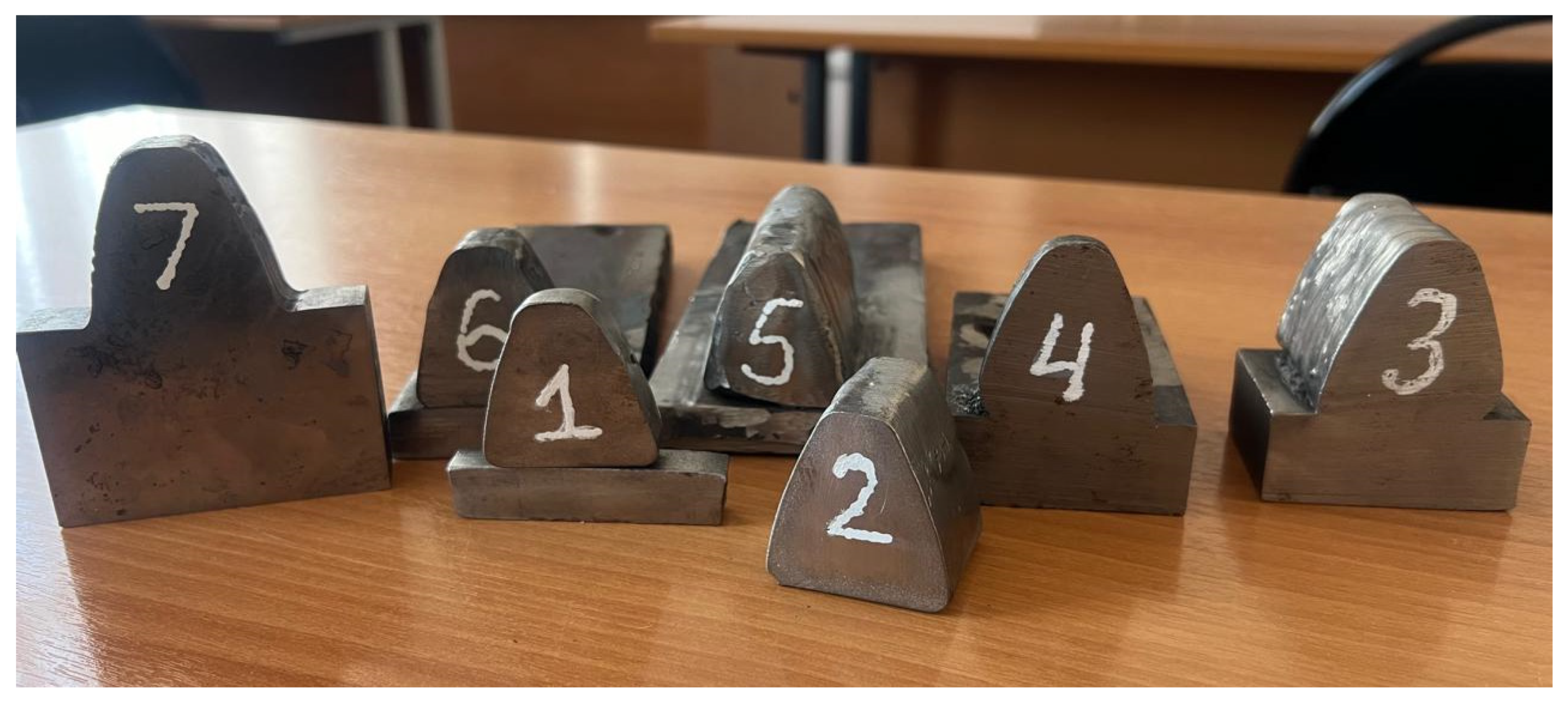
Figure 13.
Graph of voltage and current change at water flow rate Q = 3.5 l/min.
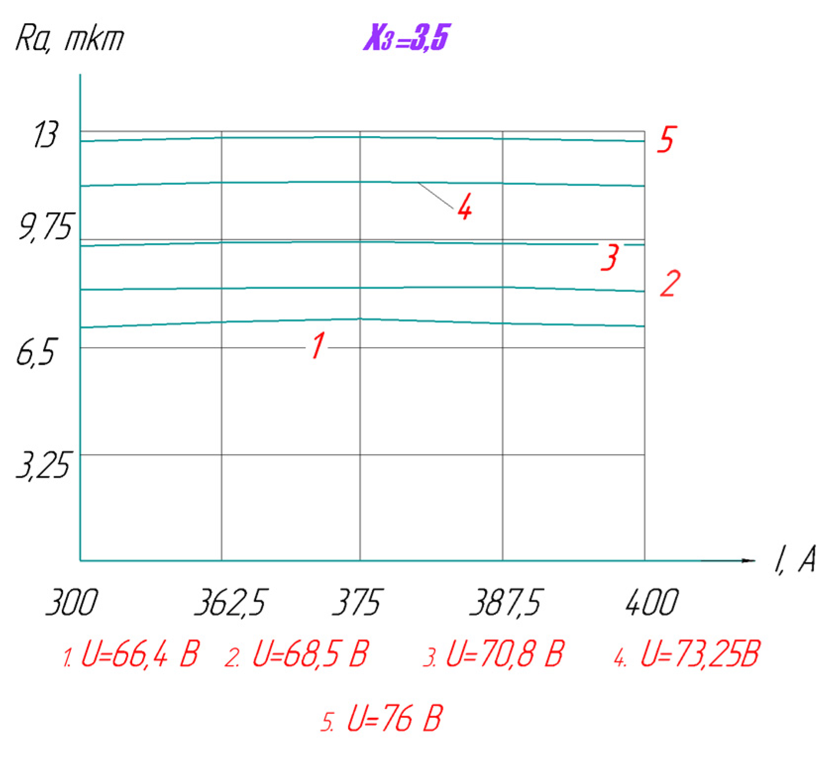
Figure 14.
Graph of change of current value at slag bath voltage U=76V.
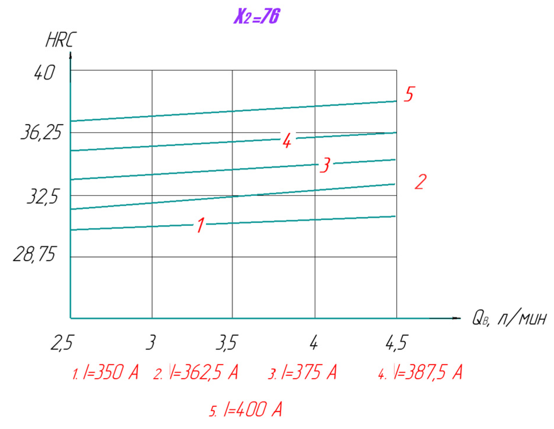
Figure 15.
Tooth surfacing process: 1-fused tooth; 2-crystallizer; 3-cooled cover.
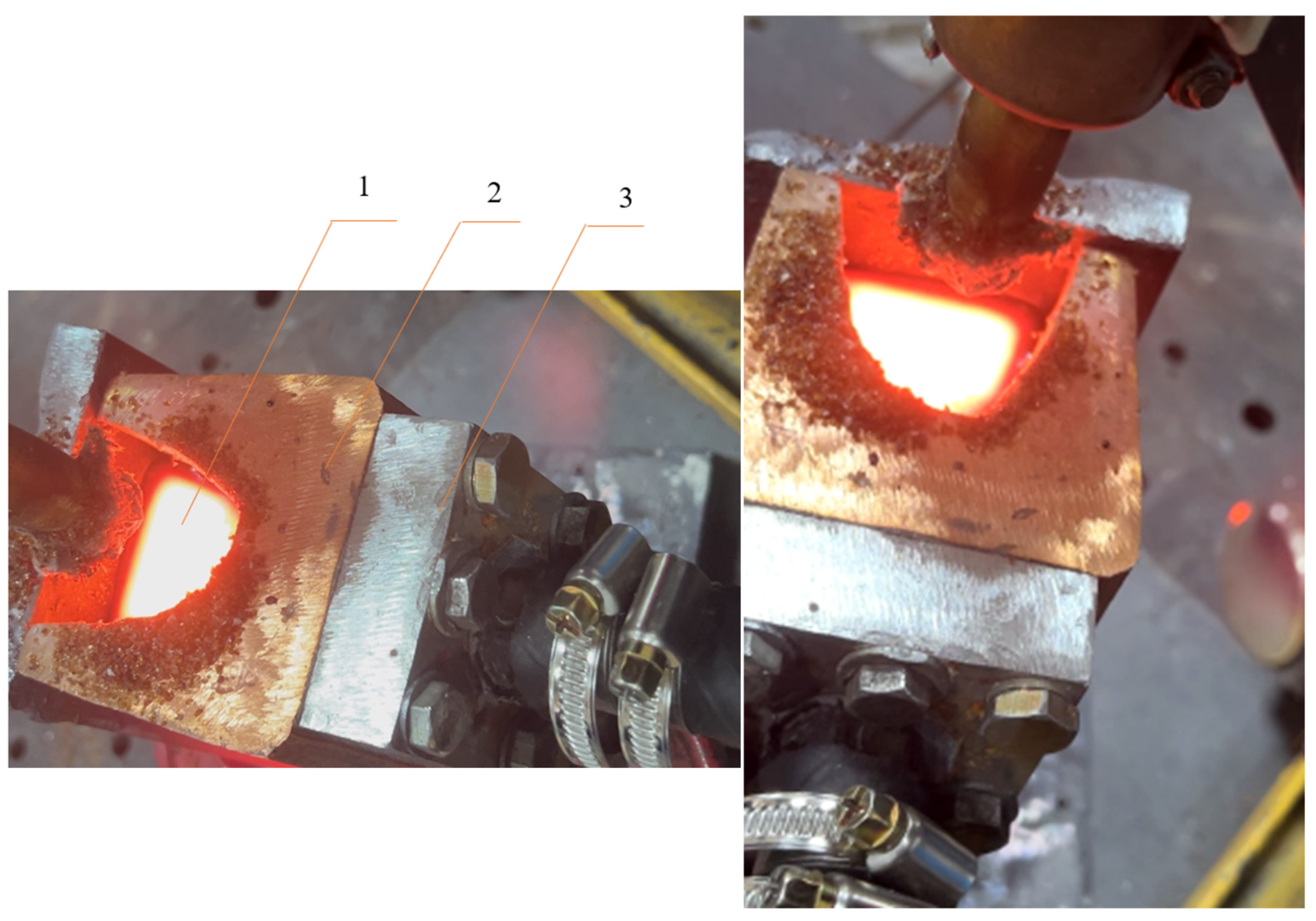
Figure 16.
Roughnesses on the surface of the clad tooth at regimes I= 362.5 - 375 A; U= 70 V; 68.5 V; Q=3.5 l/min.
Figure 16.
Roughnesses on the surface of the clad tooth at regimes I= 362.5 - 375 A; U= 70 V; 68.5 V; Q=3.5 l/min.
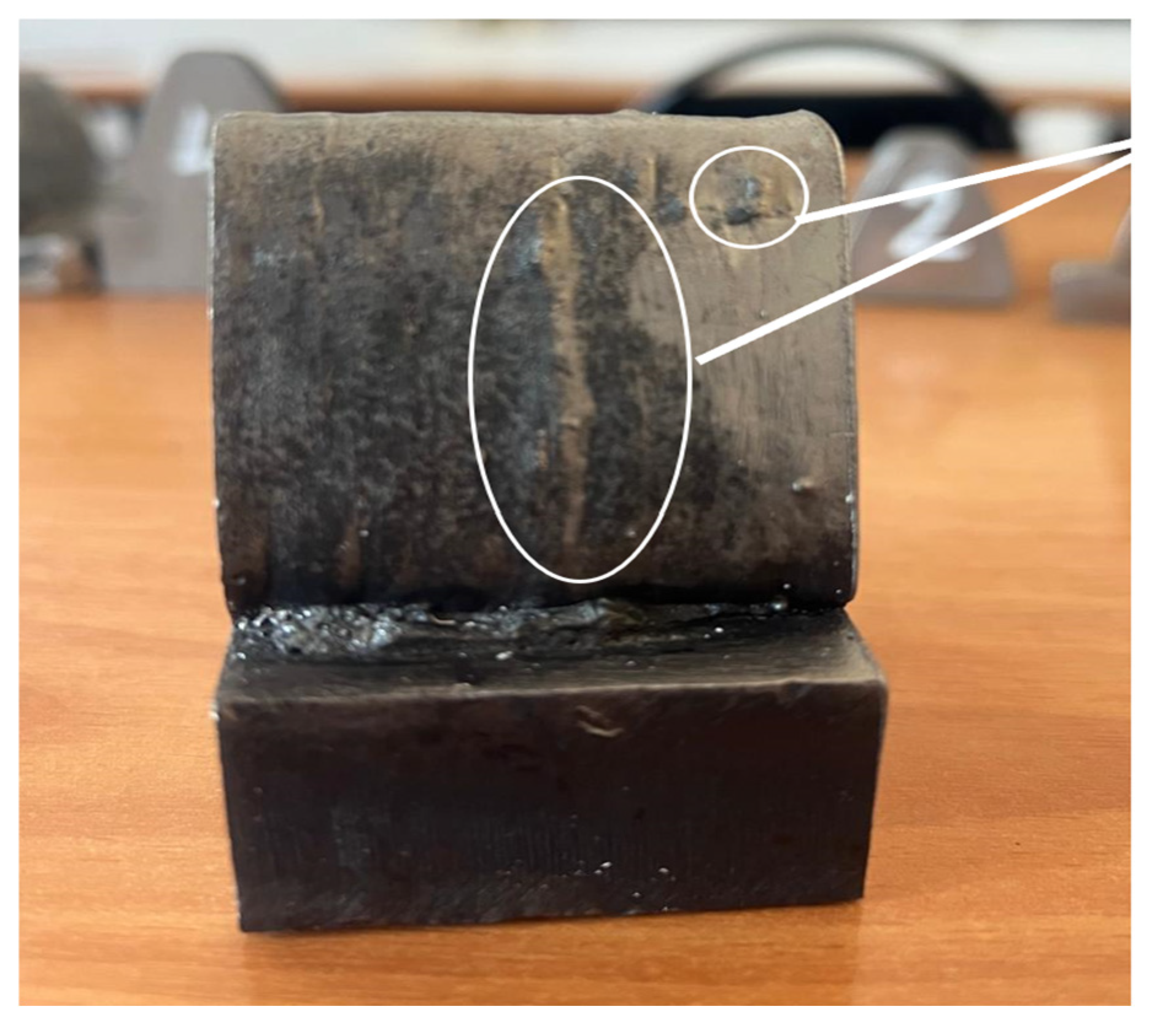
Figure 17.
Defects in the form of corrugation on the tooth surface at the mode: I= 387.5-400 A; U= 68.5-66.4 V; Q=3.5-4.5 l/min.
Figure 17.
Defects in the form of corrugation on the tooth surface at the mode: I= 387.5-400 A; U= 68.5-66.4 V; Q=3.5-4.5 l/min.
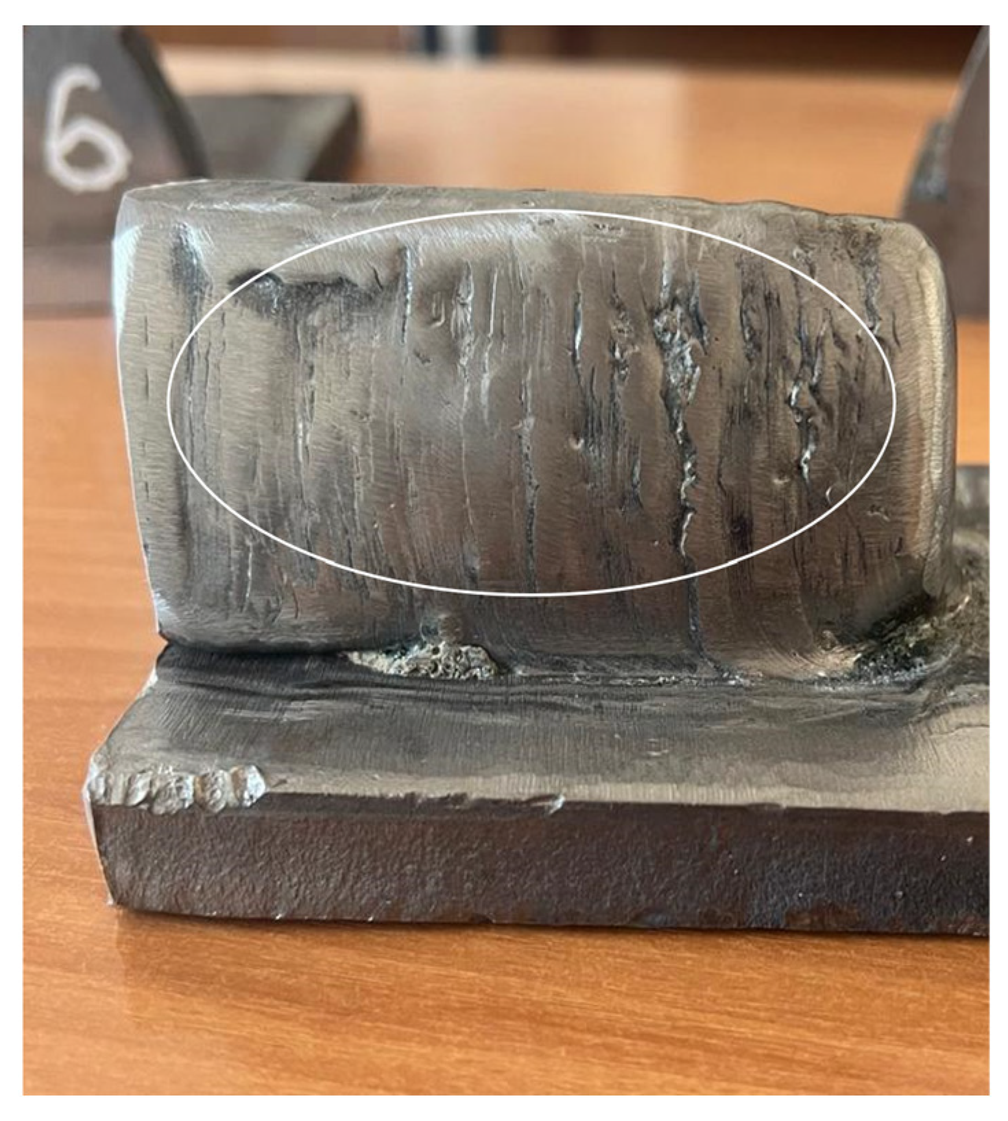
Figure 11.
Teeth surfacing process.
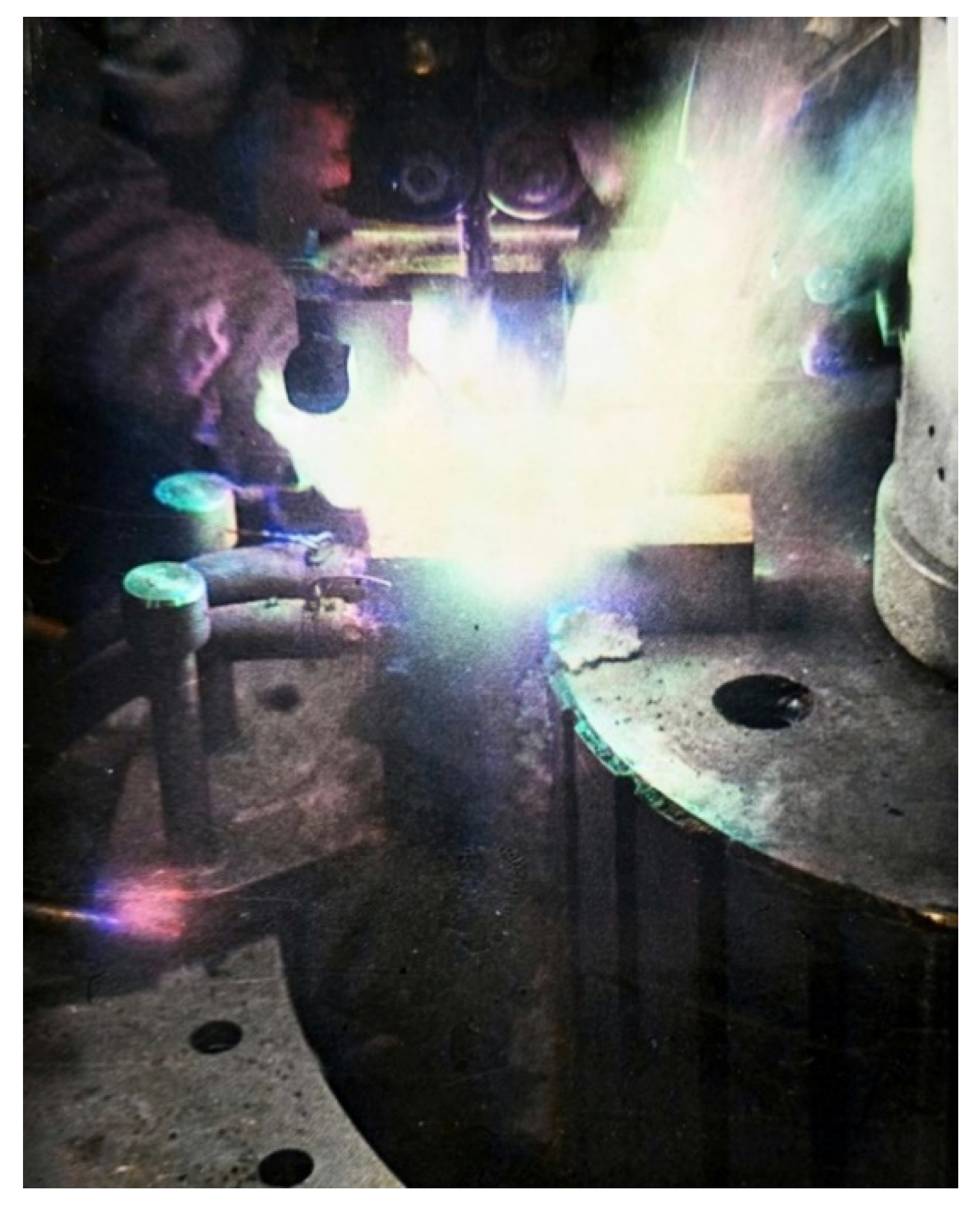

Table 1.
Characteristics of welding tractor ADF -1005Ural.
| Indicator name | Numerical data |
| Power supply voltage, V | 380 |
| Maximum welding current, A | 1000 |
| Frequency, Hz | 50/60 |
| Welding current adjustment range, A | 200 – 1000 |
| Number of welding heads | 1 |
| PV at max current, % | 100 |
| Welding speed, m/min | 0.3 - 1.0 |
| Wire diameter, mm | 3.0 - 5.0 |
| Spool weight, kg | 20 |
| Tractor supply voltage, V | 110 |
| Welding head tilt, ° | ±45 |
| Tractor weight, kg | 54 |
| Wire feed speed, m/min | 0.3 - 2.5 |
Table 2.
Three-factor experiment plan.
| Arguments | |||||
| Numbers | |||||
| X1 | X2 | X3 | |||
| No. of tests |
Limits from to |
350 | 76 | 2,5 | |
| 400 | 66,4 | 4,5 | |||
| Level 1 values 2 3 4 5 |
350 362,5 375 387,5 400 |
76 73,25 70,8 68,5 66,4 |
2,5 3 3,5 4 4,5 |
||
| Function numbers | Argument values in experiments | ||||
| Y1 | Y2 | ||||
| 1 | 10 | 26,2 | 350 | 76 | 2,5 |
| 2 | 9,2 | 27,7 | 350 | 76 | 3,5 |
| 3 | 7,9 | 26 | 350 | 76 | 3 |
| 4 | 9 | 29 | 350 | 76 | 4,5 |
| 5 | 8,6 | 28,7 | 350 | 76 | 4 |
| 6 | 9,2 | 30,6 | 362,5 | 73,25 | 2,5 |
| 7 | 7,9 | 34,8 | 362,5 | 73,25 | 3,5 |
| 8 | 7,5 | 32 | 362,5 | 73,25 | 3 |
| 9 | 11,4 | 31,6 | 362,5 | 73,25 | 4,5 |
| 10 | 11,1 | 33,4 | 362,5 | 73,25 | 4 |
| 11 | 11,6 | 33 | 375 | 70,8 | 2,5 |
| 12 | 12 | 31,3 | 375 | 70,8 | 3,5 |
| 13 | 11,8 | 33,8 | 375 | 70,8 | 3 |
| 14 | 13 | 35 | 375 | 70,8 | 4,5 |
| 15 | 12,8 | 35,7 | 375 | 70,8 | 4 |
| 16 | 13,1 | 32,78 | 387,5 | 68,5 | 2,5 |
| 17 | 13,8 | 30,78 | 387,5 | 68,5 | 3,5 |
| 18 | 13,5 | 30,9 | 387,5 | 68,5 | 3 |
| 19 | 14,1 | 29,2 | 387,5 | 68,5 | 4,5 |
| 20 | 14 | 30,1 | 387,5 | 68,5 | 4 |
| 21 | 14,3 | 25,7 | 400 | 66,4 | 2,5 |
| 22 | 15,1 | 25 | 400 | 66,4 | 3,5 |
| 23 | 14,9 | 25,3 | 400 | 66,4 | 3 |
| 24 | 15,7 | 24,6 | 400 | 66,4 | 4,5 |
| 25 | 15,5 | 24,98 | 400 | 66,4 | 4 |
Disclaimer/Publisher’s Note: The statements, opinions and data contained in all publications are solely those of the individual author(s) and contributor(s) and not of MDPI and/or the editor(s). MDPI and/or the editor(s) disclaim responsibility for any injury to people or property resulting from any ideas, methods, instructions or products referred to in the content. |
© 2025 by the authors. Licensee MDPI, Basel, Switzerland. This article is an open access article distributed under the terms and conditions of the Creative Commons Attribution (CC BY) license (http://creativecommons.org/licenses/by/4.0/).
Copyright: This open access article is published under a Creative Commons CC BY 4.0 license, which permit the free download, distribution, and reuse, provided that the author and preprint are cited in any reuse.


