
Submitted:
30 June 2025
Posted:
02 July 2025
You are already at the latest version
Abstract
An analysis of cylindrical gears’ working surface after scuffing shock tests allowed for an assessment of the effect of loading conditions on the form of damage to teeth working surface. In contrast with the method of scuffing in severe conditions, where loading values are implemented gradually, a direct maximal loading – the shock loading – was used in the tests presented, not preceded by lapping the gears with a lower loading. This manner of loading considerably increases the analysed elements’ vulnerability to scuffing, allowing to judge their limit operational properties. To identify the changes and types of the teeth’s working surface damage, the following microscopy techniques were applied: scanning electron microscopy (FE-SEM) with EDS microanalyser, optical interferential profilometry (WLI), atomic force microscope (AFM), and optical microscopy. The results allowed for defining characteristic damage mechanisms and assessing the efficiency of the applied DLC coatings when it comes to resistance to scuffing in shock scuffing conditions. Tribological tests were performed by means of FZG T-12U gear test rig in a power circulating system to test cylindrical gear scuffing. The gears were made from 18CrNiMo7-6 steel and 35HGSA nano-bainitic steel and coated with W-DLC/CrN.
Keywords:
DLC coating
; cylindrical gears
; shock scuffing
; tooth’s working surface damage
1. Introduction
The problem of friction pair scuffing remains topical in the design and exploitation of machines. This stems from the rising tendency to increase loading transferred by friction elements while simultaneously decreasing their size, which considerably intensifies tribological phenomena. In tribological research, the following question is especially important: to what extent can the results of tribological tests produced in laboratory conditions be extrapolated to machine elements operating under real-world conditions? This question pertains mostly to the qualities of materials of which operating friction pairs are made. Coal mines are characterised by very difficult operating conditions. The teeth working surface of drive trains’ gears are in danger of intense damage there. The gearbox oil is polluted with solid particles. Similar difficult conditions can be found in construction, forest, or agricultural industries. As a result, the gearbox service life is shortened. In extreme situations, a weakened tooth can break, removing the gearbox from exploitation. To prevent the problem of intense wear and lengthen the service life of gearboxes, teeth surfaces are modified in different ways, including the application of thin, low-friction coatings. Currently, DLC coatings (DLC – diamond-like carbon) are the most frequently tested when it comes to tribological properties. Good anti-scuffing qualities result from the presence of amorphous carbon (sp2) in the outer layer of the coating. Wolfram, chromium, or silicon are added to these coatings (W-DLC, Cr-DLC, Si-DLC [1,2,3,4,5,6,7,8,9,10,11,12,13,14,15,16,17,18] in order to protect the base surface from abrasion.
The results identifying changes on the working surfaces of the drive trains’ gears made from 18CrNiMo7-6 and 35CrMnSiA steel and coated with W-DLC/CrN, after scuffing (FZG) tests in severe conditions and with a gradually increasing loading of the friction pair were presented in [19]. In order to further analyse the mechanisms of damage, the tests were continued, accounting for the shock loading of cylindrical toothed gear’s operation, corresponding to dynamic, sudden overloading typical for emergency conditions or operation in a difficult environment. The purpose of the tests was to determine the effect of the manner of loading of the cylindrical toothed gear on the form of damage to the teeth’s working surface through analysing changes on the teeth’s working surface using microscopy methods.
2. Materials and Methods
The shock scuffing tests were conducted on FZG A10 test gears, with a 10 mm wide pinion and a 20 mm wide gear. The teeth’s working surface was ground longitudinally (Figure 1).
Test gears made of 18CrNiMo7-6 steel of 733±14 HV hardness and made of 35CrMnSiA nano-bainitic [20,21,22,23,24] steel of 671±20 HV hardness were used. A coating with the commercial name Balinit C Star (made of W-DLC/CrN coating material) was applied on the gears’ teeth. The company Oerlikon Balzers Coating Poland conducted the process of coating the teeth’s surface using the PACVD technology. The W-DLC/CrN coating applied on 18CrNiMo7-6 steel was 4.8 µm thick, and the coating on 35CrMnSiA steel was 3.8 µm thick.
The coating adhesion tests were performed by scratching with Indenter Rockwell C on the REVETEST CSEM Scratch-Tester. The loading progressively increased up to 100 N/min by 10 N/mm. The scratching length was 10 mm. The values of the forces inducing the characteristic mechanisms of coating damage were determined by microscopic observations of the coating damage in the scratched area. The adhesion for the W-DLC/CrN coating on 18CrNiMo7-6 steel was 40 N, while it was 50 N for the coating on 35CrMnSiA steel. The hardness of the W-DLC/CrN coating on 18CrNiMo7-6 steel was 13 GPa, in turn, it was 10 GPa for the coating on 35CrMnSiA steel.
The tribological, component FZG shock scuffing tests were performed following the S-A10/16,6R/90 method described in the FVA No. 243, June 2000 [25,26,27,28,29,30,31] working paper. The tests were conducted at the T-12UF test stand in the Łukasiewicz – Institute of Sustainable Technologies, Poland [32,33,34,35].
Each test began with a stable rotational speed and identical initial temperature. As part of the shock scuffing method, the loading is not increased gradually from the lowest value, but the test gears are put under such (“shock”) loading that scuffing is expected straightaway. The maximal loading value is 12, which creates a loading torque of 535 Nm and a Hertzian stress of 2.6 GPa (Table 2). This way, the gears’ run-in is avoided, thus, their scuffing susceptibility is increased. The tests are performed until the criterion of scuffing is met, judged by the measurement of the area of the surface showing wear traces on the pinion. The criterion is considered to be fulfilled if damage to the pinion’s teeth shows on a surface larger than 100 mm2.
Test conditions:
- motor rotational speed 3000 rpm
- circumferential speed 16.6 m/s
- run duration 7 min. 30 s
- maximum load stage 12
- maximum loading torque 535 N·m
- maximum Hertzian stress 2.6 GPa
- initial lubrication oil temperature 90oC (uncontrolled after starting the run)
- type of lubrication dip lubrication (oil quantity ca. 1.5 dm3)
Shell Omala S4 GX 320 commercial industrial gear oil with PAO (polyalphaolefin) synthetic base of the 6/6 EP AGMA viscosity class was used in the tests
3. Results
The applied microscopy techniques allowed for the observation of wear propagation after shock scuffing tests, with a maximal 12th loading level of the cylindrical toothed gear. The techniques enabled the identification of the type of damage usually present on the pinion’s tooth working surface, characteristic for scuffing tests (Table 1).
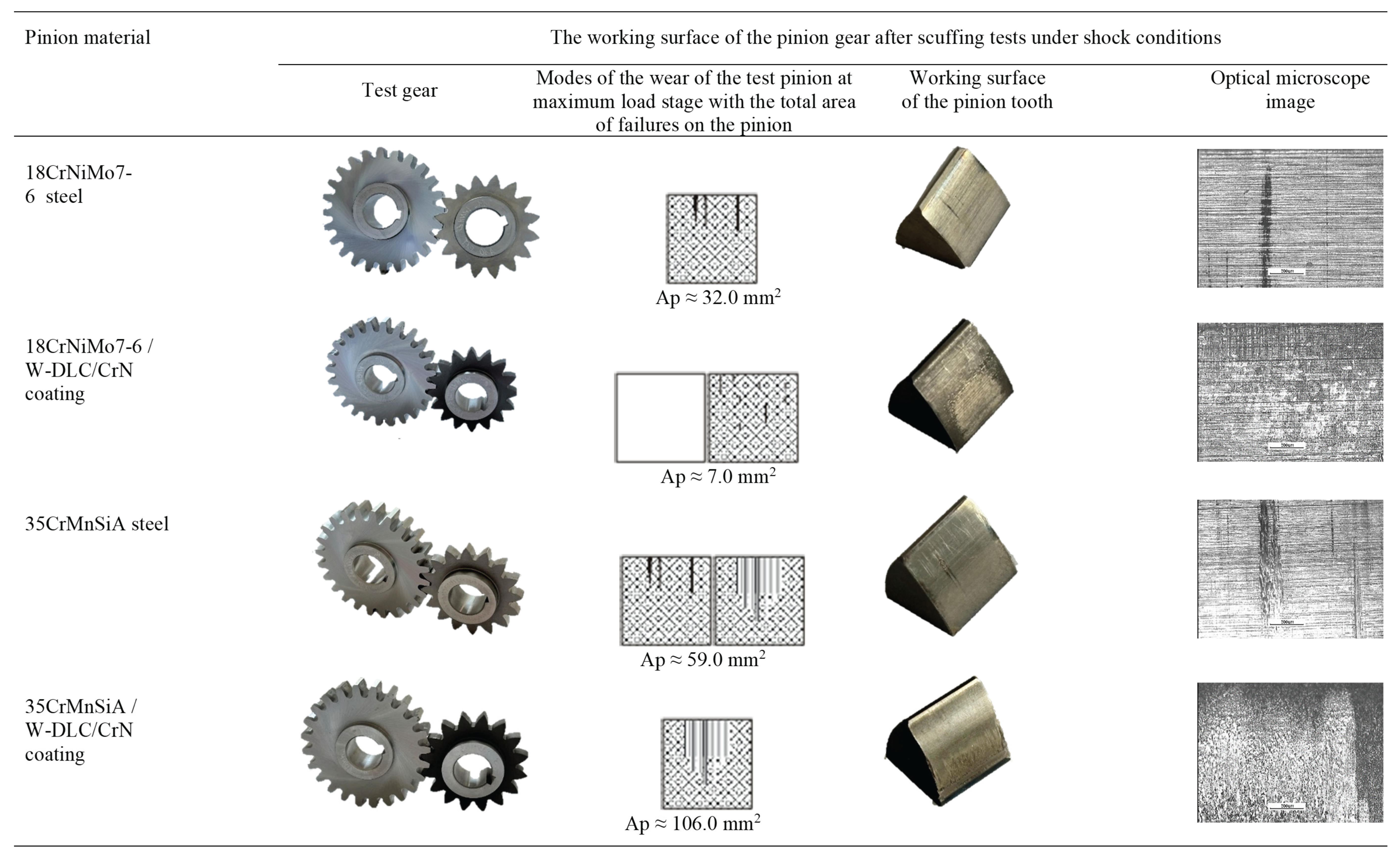
On the basis of microscopic image analysis, the mechanisms of scuffing on the cylindrical gears’ teeth working surface were described. The most common damage influencing the surface’s state was observed. The surface damage and wear trace diagrams, the images of shock scuffing tests performed at the highest, maximal 12th loading level, and of the pinion’s teeth damaged surface are presented in Table 2. By analysing the images of the teeth surface area of the 2.5 mm x 2.5 mm with the use of MM-40 optical microscope from Nikon, the most frequent damages for the given pairings were observed.
Out of all the tested material combinations, the pairing with the pinion of 35CrMnSiA/W-DLC/CrN steel was decidedly the least resistant to scuffing. The wear value of the teeth’s area was Ap = 106 mm2. The damage on the pinion’s surface covered an area of more than 100 mm2. Thus, according to the assessment criterion, the pinion’s working surface was seizured. Plenty of damage in the form of grooves made by the tooth root (Table 2) was identified microscopically. The pairing with the pinion of the 35CrMnSiA steel was another material pairing for which the wear value of the pinion’s surface was worrying, because it amounted to Ap = 59.0 mm2. There was no scuffing, according to the criterion of its assessment, but the surface’s microscopic analysis demonstrated the presence of micropitting wear forms and noticeable scuffing areas. Scratches and polishings were observed on the working surface of the pinion made of 18CrNiMo7-6 / W-DLC/CrN steel. The shock scuffing method allowed for differentiating the analysed material pairings of gears.

Table 2.
The gear tooth’s working surface after shock scuffing, maximally at the 12th stage of failure load.
Table 2.
The gear tooth’s working surface after shock scuffing, maximally at the 12th stage of failure load.
 |
The results of SEM tests performed with the scanning electron microscope model SU-70 from Hitachi, integrated with an NSS 312 energy dispersive spectrometer EDS by Thermo Scientific, are presented in Figure 2. The SEM images were made of the working surface of the pinion’s teeth before and after shock scuffing tests on an area of 100 µm x 100 µm. The teeth’s working surface before the scuffing tests is characterised, in the case of steel, with a texture characteristic for longitudinal grinding. In turn, in the case of modified surface, drops typical for applied PVD coatings were observed. Damage in the form of grooves was observed after the scuffing tests on the surface of a tooth made of 18CrNiMo7-6 steel. On the other hand, break-outs and chippings characteristic for micropitting were identified on the surface of a tooth made of 35CrMnSiA steel.
The coating on the tooth made of 18CrNiMo7-6 steel, as well as on the tooth made of 35CrMnSiA steel, was partially damaged and worn, which was confirmed by the EDS elemental decomposition analysis, showing changes in the outer layer chemical composition (Figure 4). By analysing the map of the EDS elemental decomposition on the surface of the tooth made of 18CrNiMo7-6 steel with W-DLC/CrN coating, after the shock scuffing tests, it was observed that the W-DLC layer was worn through to the CrN interlayer.
A different manner of loading the tooth’s working surface produced a vastly different test result for this pairing than in the case of scuffing in severe conditions, during which the surface made of 35CrMnSiA steel preserved its coating without visible damage [19].
The elemental decomposition of the working surface of a tooth made of 18CrNiMo7-6 steel with a W-DLC/CrN coating and of 35CrMnSiA steel with a W-DLC/CrN coating before the shock scuffing tests is presented in Figure 3. The map of wolfram decomposition was marked pink. In turn, Figure 4 shows the maps of elemental decomposition after the shock scuffing tests.
Figure 3.
The SEM images and maps of EDS elemental decomposition of the working surface of a tooth made of 18CrNiMo7-6 steel and coating and 35CrMnSiA steel and coating, made before the shock scuffing tests (1500x magnification).
Figure 3.
The SEM images and maps of EDS elemental decomposition of the working surface of a tooth made of 18CrNiMo7-6 steel and coating and 35CrMnSiA steel and coating, made before the shock scuffing tests (1500x magnification).
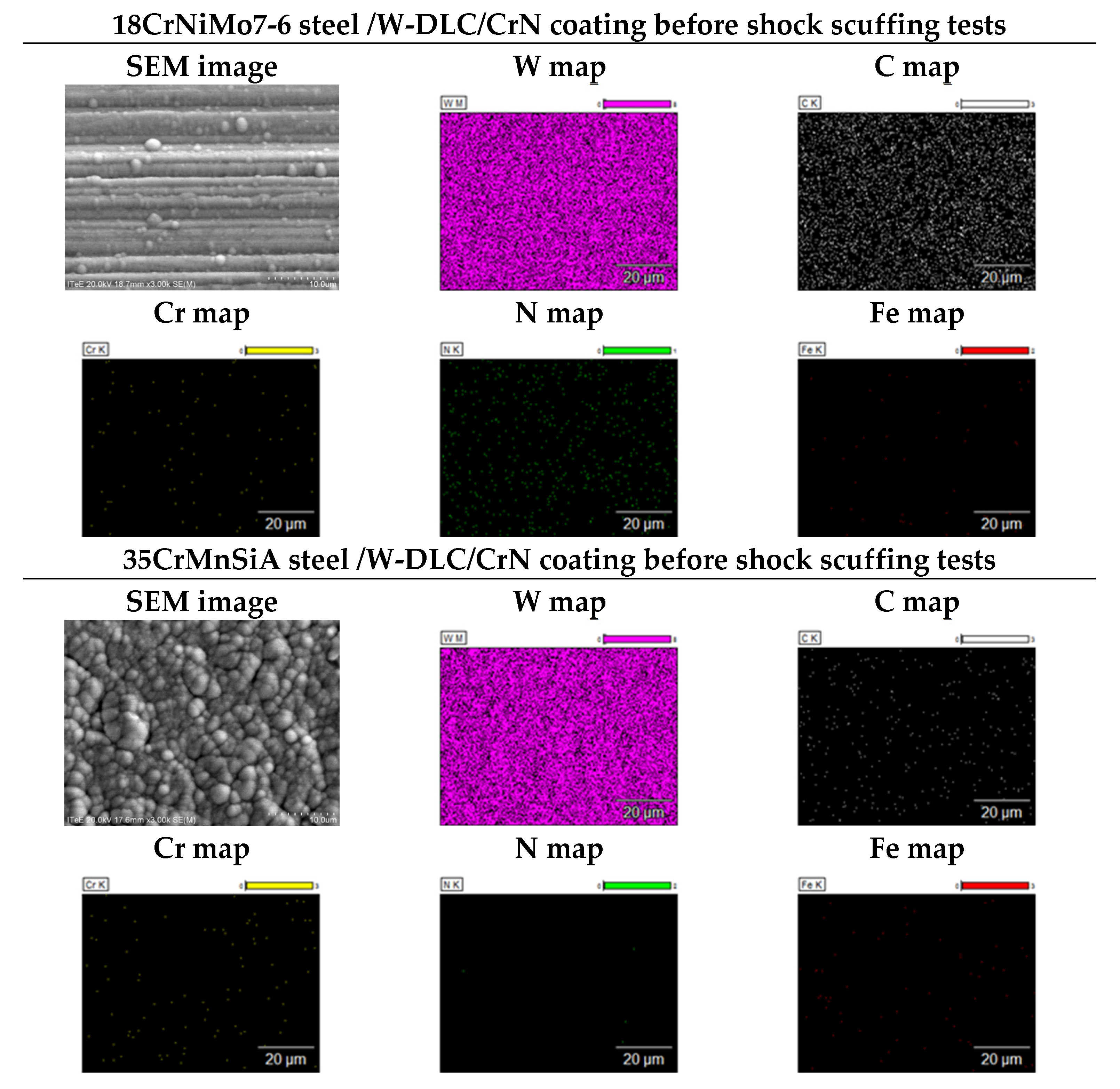
Figure 4.
The SEM images and maps of EDS elemental decomposition of the working surface of a tooth made of 18CrNiMo7-6 steel and coating and of 35CrMnSiA steel and coating, produced after the shock scuffing tests (1500x magnification).
Figure 4.
The SEM images and maps of EDS elemental decomposition of the working surface of a tooth made of 18CrNiMo7-6 steel and coating and of 35CrMnSiA steel and coating, produced after the shock scuffing tests (1500x magnification).
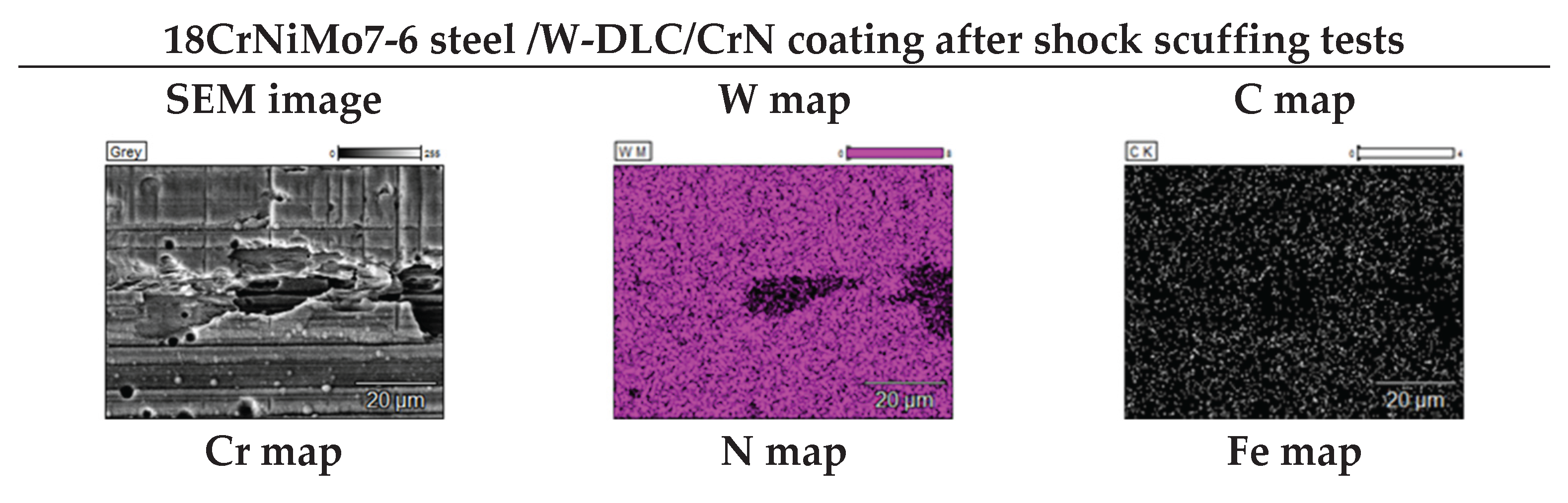
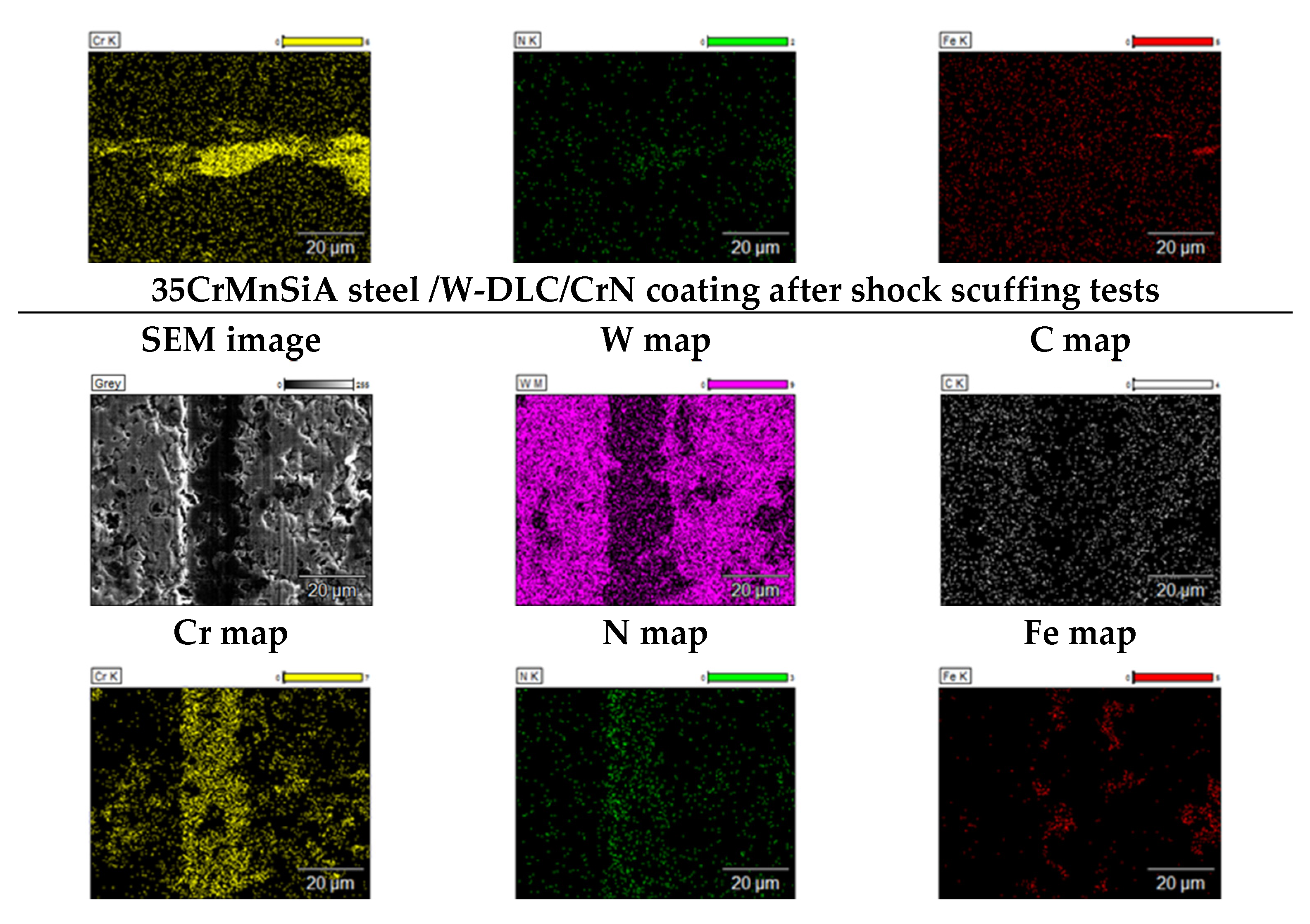
In both cases, the outer layer of the W/DLC coating was damaged, which is confirmed by the lack of wolfram on the EDC elemental decomposition maps (in pink). On the decomposition maps, chromium (marked with yellow) is present on the whole analysed surface, proving that the CrN layer was not worn. Areas in which the base surface was completely uncovered were also noted. This is confirmed by the presence of iron on the decomposition maps (in red).
The 3D microscopic images of 20 µm x 20 µm teeth’s working surface generated with an AFM Q-scope 250 atomic force microscope from Quesant Instrument Corporation are shown in Figure 5. The microscope has shown details of the surface formation before and after the shock scuffing tests. The nature of the changes observed on the surface confirmed the characteristics of the changes shown using SEM. Due to running-in, polishing traces were removed from the surface of the tooth made of 18CrNiMo7-6 steel. The surface of the 35CrMnSiA steel/W-DLC/CrN tooth was damaged, numerous pits were observed, and grooves perpendicular to the polishing direction appeared. The surface of the tooth made of 35CrMnSiA steel behaved similarly. In the case of the 18CrNiMo7-6 steel/ W-DLC-CrN tooth, the steel base surface with some traces of polishing is visible after the coating’s removal.
The images of the 1600 µm x 1600 µm working surface of the pinion, made with WLI interferometric microscope produced by Taylor Hobson, are presented in Figure 6 and Figure 7. Figure 6 shows a 3D microscale view of the pinion’s working surface before the scuffing tests, while Figure 7 shows 3D microscale images after scuffing tests. The state of the measured surface was described with the vertical dimensions of the tested surface marked with the following symbols: Sp – maximal rising height, Sv – maximal pit depth, Sz – maximal surface elevation, Sa – arithmetic average surface roughness deviation, Sq – root mean square surface roughness deviation.
The use of the interferometric microscope in the working surface testing of the pinion’s tooth allowed for presenting the surface spatially as well as a quantitative analysis of qualities of the tested area’s formation. It was observed that the surface of the tooth made of 18CrNiMo7-6 steel after the scuffing tests is characterised by the lowest values of all the analysed roughness parameters. In turn, the highest value of the Sz parameter, above 10.0 µm, was noted in the case of coated surfaces, both for 18CrNiMo7-6 steel and 35CrMnSiA steel. The highest Sv value of 7.043 µm was present in 35CrMnSiA steel with a coating. This points to a considerable surface damage compared to the state of the surface before the tribological tests. In the case of the working surface of the 35CrMnSiA steel tooth, pits described with the Sv parameter of 4.047 µm were observed, which suggests the damage of the tooth’s working surface.
4. Conclusions
Tests conducted at the maximal, 12th stage of shock loading allowed for the assessment of the effectiveness of used materials and protective coatings when it comes to resistance to scuffing. The following conclusions were reached after a microscopic analysis of the pinion’s tooth working surface:
- 35CrMnSiA steel pinions with W-DLC/CrN coating were seizured under shock loading. The coating proved insufficient under extreme overloading conditions.
- Scuffing areas were observed on the 35CrMnSiA steel tooth’s surface.
- 18CrNiMo7-6 steel pinions without the coating were not seizured even under the highest, 12th stage of loading. This proves a much higher material resistance of this steel to scuffing compared with 35CrMnSiA steel.
- 18CrNiMo7-6 steel teeth’s surfaces, coated with -DLC/CrN, did not show any signs of scuffing under the maximal loading either. The combination of a high-quality base material and a coating proved effective under shock scuffing conditions.
The effect of the type of loading on the resistance to scuffing was deemed important based on the microscopic observations (SEM, AFM, WLI, optical microscopy) of the 35CrMnSiA steel pinion’s teeth working surface coated with W-DLC/CrN. A lower resistance to scuffing was observed under shock loading, which corresponds to operation in industrial settings, than in tests under severe conditions [19]. The tooth’s working surface was damaged and seizured despite the use of coating. This suggests that the W-DLC/CrN coating efficiency under shock loading conditions may be limited and requires further optimalisation when it comes to both the layer structure and mechanical qualities of the coating and its adhesion to the base surface.
Author Contributions
Conceptualization, E.O.-S.; Methodology, E.O.-S..; Formal analysis, E.O.-S., A.N.W., and R.M.; Investigation, E.O.-S., M.G., A.M.-S., E.S.; Writing—original draft preparation, E.O.-S..; Writing—review and editing, R.M., A.N.W.; Visualization, E.O.-S..; Supervision, R.M., A.N.W.; Project administration, A.N.W.; funding acquisition A.N.W.; All authors have read and agreed to the published version of the manuscript.
Funding
The study was carried out as part of two projects financed by the National Centre for Research and Development, Poland: “Development of innovative hybrid surface layers composed of anti-wear coatings dedicated to gears for conveyor drive assemblies working in difficult operating conditions”. No. TECHMATSTRATEG-III/0028/2019 and “Development of an innovative technology for the manufacture of toothed components with hybrid surface layers with a nanostructure base for the drive units of conveyors designed to be used in extreme operating conditions”. No. POIR.04.01.04-00-0064/15.
Institutional Review Board Statement
Not applicable.
Informed Consent Statement
Not applicable.
Data Availability Statement
The data presented in this study are available on request from the corresponding author. The data is not publicly available due to the fact that information regarding the transmission technology is reserved by the manufacturer.
Conflicts of Interest
The authors declare no conflicts of interest.
Abbreviations
The following abbreviations are used in this manuscript:
| FLS | failure load stage |
| FZG | the Gear Research Centre (Forschungsstelle fur Zahnrader und Getriebebau, FZG) of the Technical University of Munich |
| DLC | Diamond – Like Carbon coating |
| SEM | Scanning Electron Microscope |
| EDS | Energy Dispersive Spectrometer |
| WLI | White Light Interferometer Microscope |
| AFM | Atomic Force Microscope |
| Ra | profile roughness [µm] |
| Sa | surface roughness [µm] |
| Sp | maximum peak height [µm] |
| Sv | maximum indentation depth [µm] |
| Sz | maximum surface height [µm] |
| Sq | mean square deviation of the surface roughness [µm] |
| Ap | wear surface area [mm2] |
References
- Evaristo, M.; Fernandes, F.; Cavaleiro, A. Influence of the alloying elements on thetribological performance of DLC coatings in different sliding conditions. Wear 2023, 526-527, 204880. [CrossRef]
- Forsberg, P.; Gustavsson, F. Renman,, V.; Hieke A.; Jacobson, S. Performance of DLC coatings in heated commercial engine oils. Wear 2013, 304(1-2), 211-222. [CrossRef]
- Rincon, C.; Zambrano, G.; Carvajal, A.; Prieto, P.; Galindo, H.; Martinez, E.; Lousa, A.; Esteve, J. Tungsten carbide/diamond-like carbon multilayer coatings on steel for tribological applications. Surface and Coatings Technology 2001, 148, 277–283. [Google Scholar] [CrossRef]
- Goti, E.; Mura, A.; Gautier di Confiengo, G.M.; Casalegno, V. The tribological performance of super-hard Ta:C DLC coatings obtained by low-temperature PVD. Ceramics International 2023, 49, 40193–40210. [Google Scholar] [CrossRef]
- Rajak, D. K.; Kumar, A.; Behera, A.; Menezes, P. Diamond-Like Carbon (DLC) Coatings: Classification, Properties, and Applications, Appl. Sci. 2021, 11, 4445. [Google Scholar] [CrossRef]
- Shaikh, S.; Sadeghi, M.; Cruz, S.; Ferreira, F. Recent Progress on the Tribology of Pure/Doped Diamond-like Carbon Coatings and Ionic Liquids, Coatings 2024, 14(1), 71. [CrossRef]
- Radoń-Kobus, K.; Madej, M.; Kowalczyk, J.; Piotrowska, K. Properties of Diamond-like Tungsten-Doped Carbon Coatings Lubricated with Cutting Fluid, Coatings 2024, 14(3), 342. [CrossRef]
- Martins, R.; Amaro, R.; Seabra, J. Influence of low friction coatings on the scuffing load capacity and efficiency of gears, Tribol. Int. 2008, 41, 234–243. [Google Scholar] [CrossRef]
- Vengudusamy, B.; Mufti, R. A.; Lamb, G. D.; Green, J. H.; Spikes, H. A. Friction properties of DLC/DLC contacts in base oil, Tribol. Int. 2011, 44 (7-8), 922–932. [CrossRef]
- Kalin, M.; Vižintin, J. The tribological performance of DLC-coated gears lubricated with biodegradable oil in various pinion/gear material combinations, Wear 2005, 259, 1270–1280. [CrossRef]
- Tuszyński, W.; Michalczewski, R.; Osuch-Słomka, E.; Snarski-Adamski, A.; Kalbarczyk, M.; Wieczorek, A.; Nędza, J. Abrasive wear, scuffing and rolling contact fatigue of DLC-coated 18CrNiMo7-6 steel lubricated by a pure and contaminated gear oil, Materials 2021, 14(22), 7086. [CrossRef]
- Tuszyński, W.; et al. The effect of WC/C coating on the wear of bevel gears used in coal mines. Materials Science (Medžiagotyra) 2015, 21, 358–363. [Google Scholar] [CrossRef]
- Barth, Y. J.; Sagraloff, N.; Egger, G.; Tobie, T.; Stahl, K. Investigations on Ways to Improve the Scuffing and Wear Behavior of Oil-Free Water-Based Lubricants for Gear Applications, J. Tribol. 2024, 146, (5), 054601. [Google Scholar] [CrossRef]
- Ronkainen, H.; Elomaa, O.; Varjus, S.; Kilpi, L.; Jaatinen, T.; Koskinen, J. The influence of carbon based coatings and surface finishon the tribological performance in high-load contacts, Tribology International 2016, 96, 402–409. [CrossRef]
- Beilicke, R.; Bobach, L.; Bartel, D. Transient thermal elastohydrodynamic simulation of a DLC coated helical gear pair considering limiting shear stress behavior of the lubricant, Tribology International 2016, 97, 136–150. [CrossRef]
- Liu, H.; Zhu, C.; Zhang, Y.; Wang, Z.; Song, Ch. Tribological evaluation of a coated spur gear pair, Tribology International 2016, 99, 117–126. [CrossRef]
- Fujii, M.; Seki, M.; Yoshida, A. Surface durability of WC/C-coated case-hardened steel gear, J. Mech. Sci. Technol. 2010, 24, 103–106. [Google Scholar] [CrossRef]
- Michalczewski, R.; Kalbarczyk, M.; Piekoszewski, W.; Szczerek, M.; Tuszynski, W. The rolling contact fatigue of WC/C-coated spur gears, J. Eng. Tribol. 2013, 227, 850–860. [Google Scholar] [CrossRef]
- Osuch-Słomka, E.; Michalczewski, R.; Mańkowska-Snopczyńska, A.; Kalbarczyk, M.; Wieczorek, A.; Skołek, E. Wear mechanisms of the working surface of gears after scuffing tests, Materials 2024, 17(14), 3552. [CrossRef]
- Ríos-Diez, O.; Aristizábal-Sierra, R.; Serna-Giraldo, C.; Jimenez, J. A.; Garcia-Mateo, C. Development of nanobainitic microstructures in carbo-austempered cast steels: Heat treatment, microstructure and properties, Metals 2020, 10(5), 635. [CrossRef]
- Rementeria, R.; Morales-Rivas, L.; Kuntz, M.; Garcia-Mateo, C.; Kerscher, E.; Sourmail, T.; Caballero, F. G. On the role of microstructure in governing the fatigue behaviour of nanostructured bainitic steels, Material Scence Engineering A 2015, 630, 71–77. [CrossRef]
- Solano-Alvarez, W.; Pickering, E.; Bhadeshia, H. K. D Degradation of nanostructured bainitic steel under rolling contact fatigue, Material Scence Engineering A 2014, 617, 156–164. [CrossRef]
- Łukaszewicz, G.; Szczygieł, M.; Wesierska-Hinca, M.; Chmielarz, K.; Wierzbicka, E.; Wasiak, K. Interrupted quenching and bainitising below Ms temperature of EN X37CrMoV5-1 hot-work tool steel: Bainitic transformation kinetics, microstructure and mechanical properties, Material Scence Engineering A 2023, 869, 144740. [CrossRef]
- Morales-Rivas, L.; Azadi, A.; Kerscher, E. Fatigue behavior of nanostructured bainite: A morphological study of crack path, Procedia Struct. Integr. 2022, 39, 515–527. [Google Scholar] [CrossRef]
- FVA Information Sheet, no. 243, Status June 2000, Method to Assess the Scuffing Load Capacity of Lubricants with High EP Performance Using an FZG Gear Test Rig, 2000. 20 June.
- Höhn, B. R.; Michaelis, K.; Eberspächer, C.; Schlenk, L. A scuffing load capacity test with the FZG gear test rig for gear lubricants with high EP performance, Tribotest Journal 1999, 5, 383–390. ,.
- Michaelis, K.; Höhn, B. R.; Graswald, C. Scuffing tests for API GL-1 to GL-5 gear lubricants”, In: Proc. 13th international colloquium tribology 2002, p. 1133-1137.
- Michaelis, K.; Höhn, B. R.; Oster, P. Influence of lubricant on gear failures-test methods and application to gearboxes in practice, Tribotest Journal 2004, 11-1, 43-56.
- Van De Velde, F.; Willen, P.; De Baets, P.; Van Geetruyen, C. Substitution of inexpensive bench tests for the FZG scuffing test - Part I: Calculations, Tribol. Trans. 1999, 42, 63–70. [Google Scholar] [CrossRef]
- Van De Velde, F.; Willen, P.; De Baets, P.; Van Geeteruyen, C. Substitution of inexpensive bench tests for the FZG scuffing test - Part II: Oil tests, Tribol. Trans. 1999, vol. 42, pp. 71-75.
- Tuszynski, W. , Michalczewski R., Szczerek M., Kalbarczyk M.: A new scuffing shock test method for the determination of the resistance to scuffing of coated gears. Archives of Civil and Mechanical Engineering (ACME), 2012, vol. 12 (4), s. 436-445. [CrossRef]
- Michalczewski, R.; Kalbarczyk, M.; Mańkowska-Snopczyńska, A.; Osuch-Słomka, E.; Piekoszewski, W.; Snarski-Adamski, A.; Szczerek, M.; Tuszynski, W.; Wulczyński, J.; Wieczorek, A. The effect of a gear oil on abrasion, scuffing, and pitting of theDLC-coated 18CrNiMo7-6 steel, Coatings 2019, 9(1), 2. [CrossRef]
- Szczerek, M.; Kalbarczyk, M.; Mańkowska-Snopczyńska, A.; Osuch-Słomka, E.; Piekoszewski, W.; Snarski-Adamski, A.; Tuszyński, W.; Wieczorek, A. N. The correlated selection of a thin coating and gear oil to increase the resistance of 18CrNiMo7-6 gears to pitting - Part 1, ASIATRIB 2018, 133, 293-295. ISBN 978-967-13625-2-5.
- Tuszyński, W.; Michalczewski, R.; Osuch-Słomka, E.; Wieczorek, A. N.; Wulczyński, J. The correlated selection of a thin coating and gear oil to increase the resistance of 18CrNiMo7-6 gears to abrasion and scuffing - Part 2, ASIATRIB 2018, 204, 450-452. ISBN 978-967-13625-2-5.
- Michalczewski, R.; Piekoszewski, W.; Szczerek, M.; Tuszynski, W. The lubricant-coating interaction in rolling and sliding contacts. Tribol. Int. 2009, 42, 554–560. [Google Scholar] [CrossRef]
Figure 1.
Test FZG gear pair, type A10, the pinion coated with W-DLC/CrN.
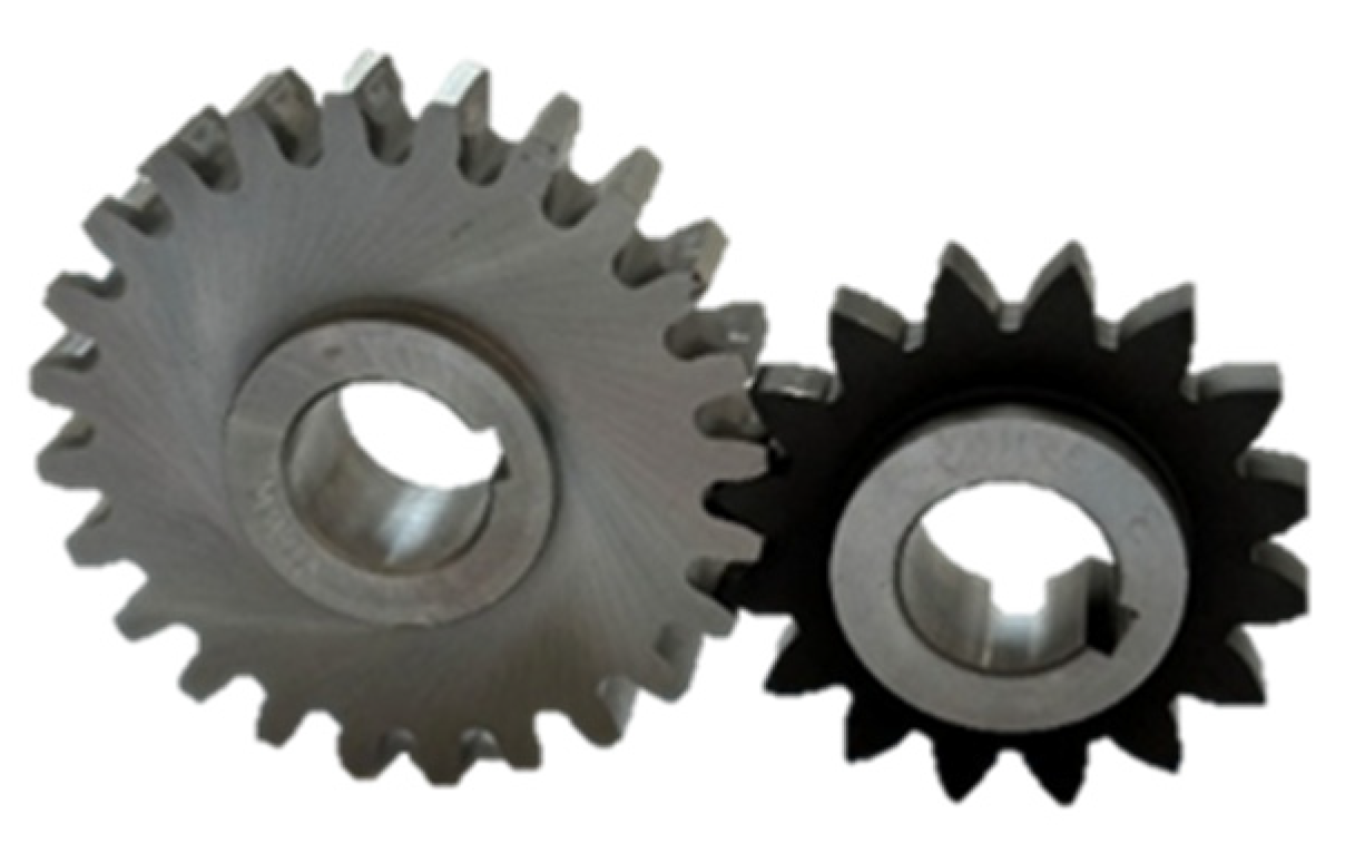
Figure 2.
The SEM images of the tooth’s working surface made before and after the shock scuffing tests.
Figure 2.
The SEM images of the tooth’s working surface made before and after the shock scuffing tests.
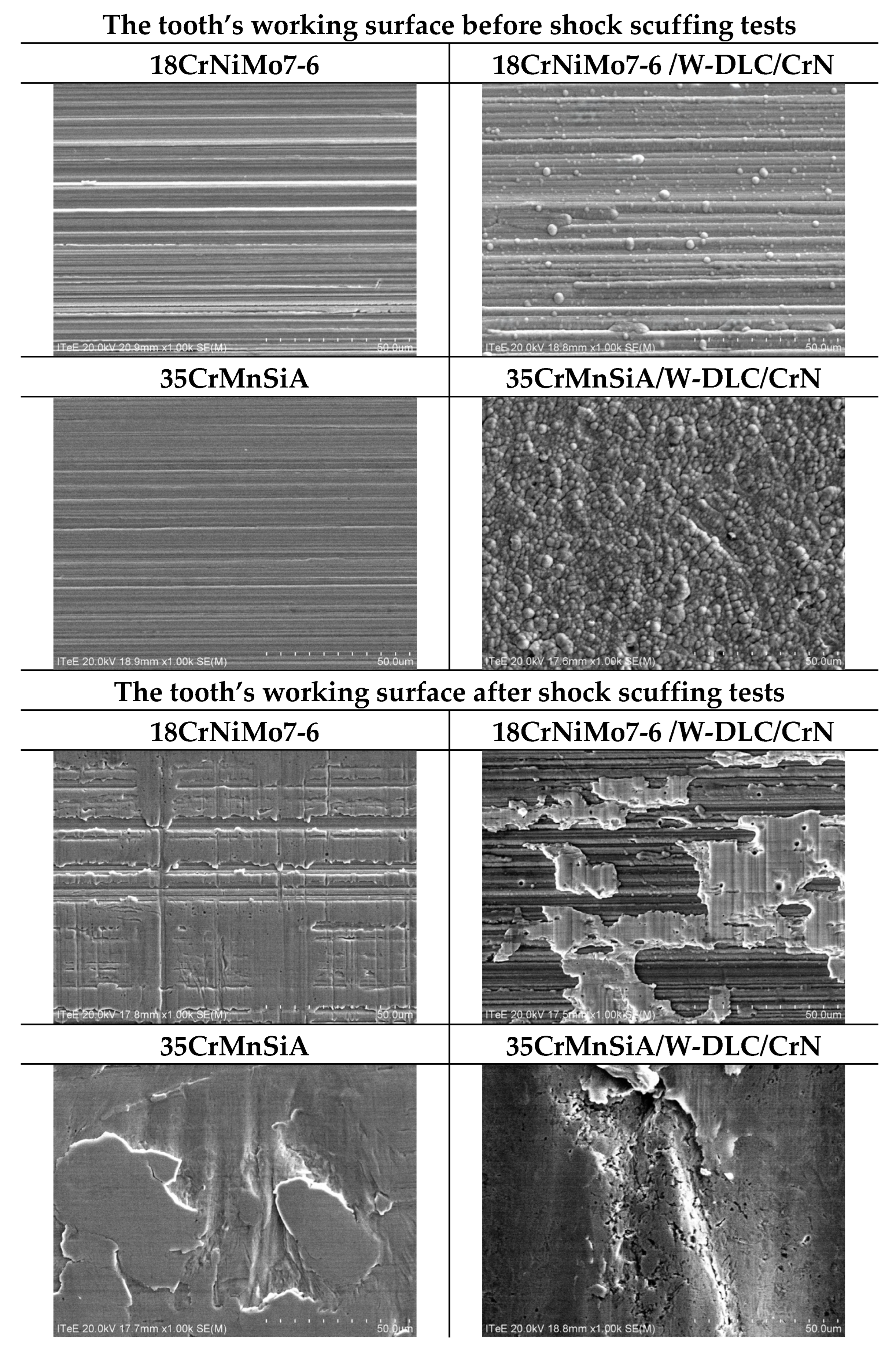
Figure 5.
The test results of formation of tooth’s working surface before and after the AFM shock scuffing tests.
Figure 5.
The test results of formation of tooth’s working surface before and after the AFM shock scuffing tests.

Figure 6.
The interferometric microscope test results of tooth’s working surface formation (3D view) before the shock scuffing tests.
Figure 6.
The interferometric microscope test results of tooth’s working surface formation (3D view) before the shock scuffing tests.
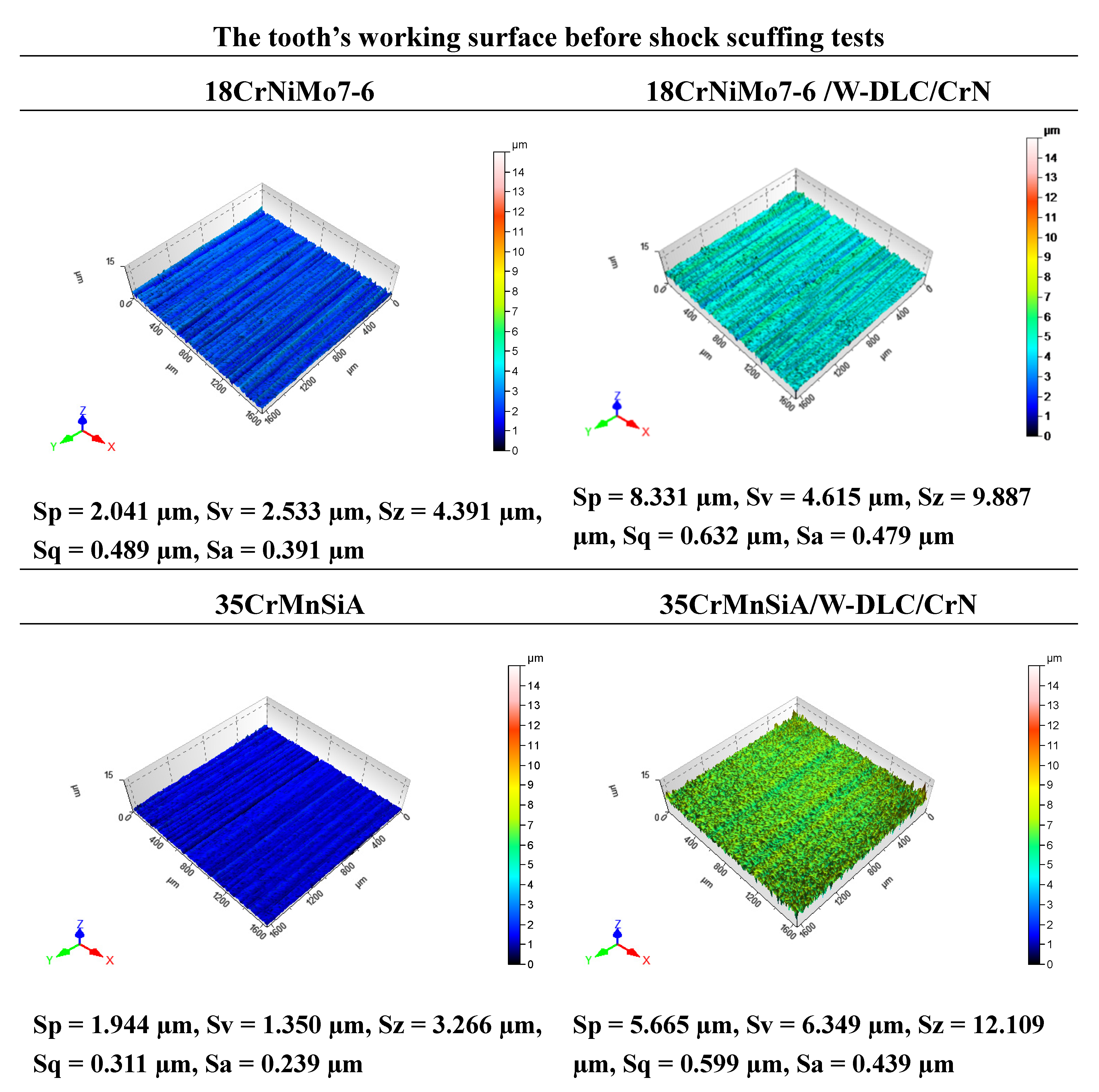
Figure 7.
The interferometric microscope test results of tooth’s working surface formation (3D view) after the shock scuffing tests.
Figure 7.
The interferometric microscope test results of tooth’s working surface formation (3D view) after the shock scuffing tests.
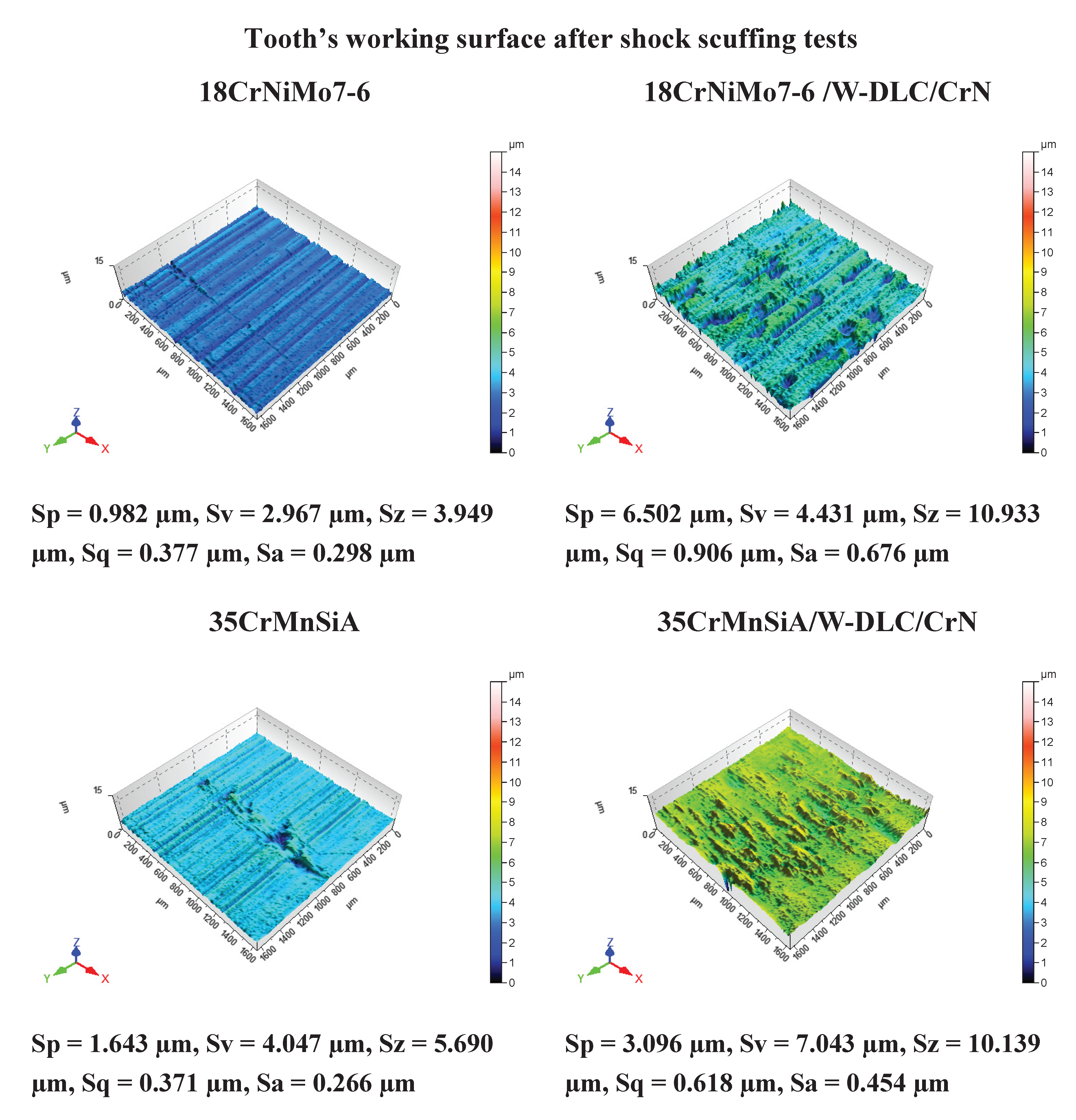
Table 1.
The type of damage present on teeth’s working surface after scuffing tests.
| Polishing | Scratches | Scoring | Scuffing |
 |
 |
 |
 |
Disclaimer/Publisher’s Note: The statements, opinions and data contained in all publications are solely those of the individual author(s) and contributor(s) and not of MDPI and/or the editor(s). MDPI and/or the editor(s) disclaim responsibility for any injury to people or property resulting from any ideas, methods, instructions or products referred to in the content. |
© 2025 by the authors. Licensee MDPI, Basel, Switzerland. This article is an open access article distributed under the terms and conditions of the Creative Commons Attribution (CC BY) license (http://creativecommons.org/licenses/by/4.0/).
Copyright: This open access article is published under a Creative Commons CC BY 4.0 license, which permit the free download, distribution, and reuse, provided that the author and preprint are cited in any reuse.


