
Submitted:
03 November 2025
Posted:
03 November 2025
You are already at the latest version
Abstract
This paper presents the results of a numerical study on the influence of the tooth root fillet manufacturing method on the bending strength of spur gears with straight teeth. A mathematical model describing the gear tooth geometry was developed, in which the transition curve at the tooth root was directly related to the applied machining process—either gear shaping or hobbing. Based on this model, a numerical procedure for calculating the bending stresses at the tooth root was formulated and verified using the finite element method (FEM). The results demonstrated high consistency between the proposed approach and FEM analysis, confirming the accuracy of the developed mathematical model and numerical methodology. The study also examined the effect of the tool fillet radius on the stress distribution in the root region. It was found that increasing the tool radius leads to a reduction in bending stresses, while the differences between the two machining methods gradually diminish. For small-tooth gears, shaping provides a more favorable stress distribution, whereas for higher gear ratios the influence of the machining method becomes negligible. The proposed methodology offers a reliable numerical framework for assessing the strength of spur gears and can be effectively used in the design of lightweight, high-performance gear transmissions for aerospace and automotive applications.
Keywords:
spur gear
; root fillet
; tooth bending stress
; gear shaping
; hobbing
; numerical analysis
; lightweight gear design
1. Introduction
This article presents a methodology for the numerical analysis of the influence of the root fillet machining method on the strength of cylindrical gears with straight teeth. A mathematical model of the tooth flank was developed, in which the geometry of the root transition curve was directly linked to the manufacturing process—shaping or broaching. A novel approach to calculating bending stresses at the tooth root was proposed, based on a numerical method utilizing discrete integration, which allowed for high accuracy compared to classical analytical methods. The results obtained using the proposed method were validated with the finite element method (FEM), and the differences between both approaches were compared and discussed.
Bending stresses at the tooth root are one of the key factors determining gear strength. Their values directly depend on the shape of the root transition curve, the radius of the cutting tool, and the gear manufacturing method. In gears with a small number of teeth, bending stresses reach critical values faster than contact stresses, which may determine the selection of gear design parameters. For pinions with a number of teeth close to the minimum limit, bending stress becomes the deciding factor for selecting the module, face width, and overall gear dimensions.
As noted in the literature [1,2], accurate representation of the tooth geometry and contact pattern between teeth is crucial for correct root stress estimation. In [1], the author presents an analytical model of load distribution in gears with a high contact ratio, while in [2], the authors proposed a combined multibody model and full FEM contact model, which enabled stress distribution assessment under dynamic operating conditions.
Equally important are studies concerning material and geometric aspects of the tooth root. In [3], the author developed a strength model based on material defect analysis, taking into account the influence of micro-inclusions on the bending strength of the tooth base. In [4], the authors simulated the actual generating gear cutting process, allowing them to evaluate the impact of the manufacturing method on the actual fillet geometry. The results of study [5] confirmed the necessity of verifying analytical models using numerical methods, as discrepancies between them can be significant—especially for gears with a small number of teeth.
In works [6,7,8,9], various approaches to gear strength analysis were presented. In [6], a multiaxial fatigue assessment method was proposed; in [7], a modified approach to root stress calculation for gears with high contact ratios was developed; in [8], the authors proposed a fast semi-analytical algorithm to reduce computation time in contact analyses. Study [9] introduced a methodology for statistical evaluation of gear strength based on experimental data, enabling calibration of numerical results against physical testing.
In the area of root transition geometry, studies [10,11] demonstrated that modifying the shape of the transition curve leads to significant changes in the stress distribution. In [10], the author developed a strength analysis method based on a fractal contact model. In [11], the authors compared standard and non-standard root profiles, showing that elliptical or cycloidal curves can reduce maximum stresses compared to classical trochoidal geometry. In studies [12,13], the impact of rim and web thickness on root stress distribution was analyzed and the consistency of numerical results with experimental measurements was confirmed.
Particularly noteworthy are studies focusing on local geometry modifications in the root zone. In [14], the use of stress relief holes at the tooth root was investigated, demonstrating their effectiveness in reducing stress concentrations. In [15], the authors presented an example of tooth root optimization using FEM, achieving a stress reduction of approximately 13%. In [16], the authors showed that accurate representation of the root geometry affects not only stress levels but also the dynamic behavior of the gear—e.g., its natural vibration frequencies.
Further studies [17,18,19] indicate that tooth profile modifications and transition curve shape can significantly affect bending stress amplitude and gear durability. In [20], the authors emphasized that tooth deformation results from both the fillet geometry and gear body elasticity, while in [21], the authors showed that material selection and elastic properties directly influence maximum root stress values.
The review of the above literature leads to the conclusion that while gear modeling, contact analysis, and fatigue strength are broadly discussed in the literature, the influence of the actual machining method—i.e., how the root transition curve is formed—is still an underexplored topic. This study addresses the issue comprehensively by developing a mathematical model of the tooth flank, in which the transition curve geometry is determined by the cutting tool radius (ρ) and the type of process (shaping or broaching).
The research covers three main objectives:
- analysis of the influence of the cutting tool radius ρ on tooth root strength,
- comparison of the impact of shaping vs. broaching on bending stress values,
- evaluation of how a low number of teeth (close to the limiting value) affects root stress levels.
In each case, the developed mathematical model was used to generate the transition curve, and a numerical method was applied to determine stress values along the tooth root. Additionally, a formula was derived to determine the maximum applicable fillet radius for the cutting tool.
From a practical standpoint, the research findings can be applied wherever minimizing gear mass while maintaining high strength is crucial: in lightweight aerospace structures, drone drive systems, and high-performance vehicle transmissions. In such applications, even a small reduction in root stress can allow for a smaller module or narrower face width, leading to noticeable weight savings.
It is also worth noting that shaping tools are simpler than broaching tools, which makes shaping an attractive option for single-piece or precision micro-transmissions. Although broaching tools are more complex, they allow for more accurate geometry reproduction, which translates to lower stress concentrations.
This article presents numerical simulations and serves as a basis for future experimental studies, which will be detailed in subsequent publications. Their aim will be to validate the presented numerical approach and assess its industrial applicability in the production of precise, lightweight, and durable gear systems.
2. Mathematical Model of the Root Fillet
The parametric equation of the involute describing the working flank of the tooth is shown in Figure 1:
where: Rb – base radius, t – roll angle
To ensure correct orientation of the tooth flank relative to the coordinate system, the involute (1) must be rotated by an angle ξ, which is the sum of angles , and (Figure 1).
The angle η is defined by the relation:
where: s – tooth pitch, equal to the gear module divided by π/2, R – pitch radius (see Figure 1)
To determine the angle
, it is necessary to find point A (Figure 1), which represents the intersection of the involute (1) with the pitch diameter R (3):
Thus, the coordinates of point A and angle ε are given by:
Finally, using the rotation matrix (6), we obtain the final equation for the tooth flank (7):
3. Transition Curve Based on the Shaping Method
Figure 2 presents a schematic of the generating simulation process using a rack tool for the shaping method
The parametric equation of the extended involute describing the transition curve at the tooth root is:
where: hr – segment equal to the distance R – Rf, Rf – root radius of the tooth algorithm, the rounding r adius ρ of the cutting tool was taken into account (Figure 2). Consequently, equation (8) must be offset along the normal to the curve by a value determined through derivatives of the parametric equation components, generally expressed as (9):
Note that curve (8) in its basic form is oriented identically to curve (1), with curvature bulges facing the negative X-axis. To correctly align curve (8) and thus also curve (9) it is necessary to apply a mirror transformation relative to the Y-axis, i.e., xw = –xw and xw’ = –xw’.
To correctly generate the lateral surface of the tooth, curve (9) must be rotated by the sum of angles ξ and δ. The angle ξ, defined as the sum of angles (2) and (5), was previously determined during the rotation of curve (1), resulting in curve (7). However, due to the mathematical complexity of curve (9), an analytical determination of angle δ is extremely difficult. Therefore, a numerical method was used. This method is based on numerically locating point B (see Figure 1), which represents the intersection of the transition curve (9) with the base circle Rb.
Once the coordinates of point B are known, angle δ can be calculated as (10):
With the value of angle δ and by applying the rotation matrix, the final equation of the transition curve becomes (11):
Using an analogous numerical method, the final length of curve (7) can be determined by its intersection with the addendum circle Ra (point C, Figure 1), and the length of curve (11) by its intersection with the base circle Rb (point D, Figure 1).
The numerical procedure for determining point B, as well as the lengths of curves (7) and (11), was implemented in MATLAB using the “find” function to identify intersections between the curves and the corresponding gear circles.
To verify the correctness of the above equations, a plot was generated based on them (Figure 3) for sample data (Table 1), and compared with the geometry obtained from the envelope simulation of the shaping process (Figure 2). The simulation involves iterative subtraction of the tool body from the blank body, resulting in a faceted tooth structure (Figure 2). To generate a digital model of such a root fillet, CAD or CAM software can be used. Once the root fillet is obtained, the coordinates of the tool’s successive passes (1, 2, 3, 4… see Figure 2, enlarged view) can be read and plotted as in Figure 3b (12).
4. Transition Curve Based on the Broaching Method
The parametric equation of the epicycloid describing the transition curve at the tooth root is (Figure 3):
where: a – distance between the centers of the cutting tool (I) and the gear blank (II), Ra2 – root depth in the machined gear, Rt – pitch diameter of the tool, R2– pitch diameter of the gear (see Figure 4)
Schematic of the envelope-based simulation of the broaching process using a rack-type tool.
Equation (13) is then transformed analogously to equation (8), resulting in the formation of an epicycloidal root transition curve in the gear.
As in the case of the extended involute, a plot was generated based on these equations (Figure 5), using the sample parameters from Table 1, and compared with the geometry obtained from the envelope-based simulation of the broaching process (Figure 4). Points (14) were obtained from the geometric simulation using the broaching method.
5. Numerical Stress Analysis
In this study, the finite element method (FEM) was applied to verify the analytical results of strength parameter calculations for a modified spur gear tooth. The main purpose of the analysis was to confirm the analytical predictions and to determine the detailed stress distribution within the tooth, with particular emphasis on bending stresses at the tooth root. Due to the applied geometric modifications, the dominant load component was expected to arise from bending, which required precise numerical representation of the tooth-root area. Similar FEM-based approaches have been successfully employed in previous research to validate analytical calculations and to investigate bending stress distributions in gear teeth [22,23,24].
The developed numerical model enables the identification of critical stress concentrations and provides a quantitative assessment of the maximum bending stress in the modified geometry. The obtained results allow comparison of the bending strength of the modified and unmodified teeth, thus serving as a basis for evaluating the influence of geometric alterations on gear durability and performance [22,23].
5.1. Numerical Integration Method
To accurately determine bending stresses, a numerical integration method was applied.
The method is based on:
- Numerically dividing the non-working part of the tooth (regions A and B in Figure 7) into cuboids with height Δr and longitudinal dimensions b and the x-component of equations (11)/(12),
- Calculating the moment arm radius as the y-component of equations (11)/(12) minus Ra,
- Using the relationship (14) to compute bending stresses at the tooth root,
- Numerically determining the maximum value of the stress and its location.
5.2. Finite Element Method (FEM)
To verify the accuracy of the obtained results, FEM analysis was conducted (Figure 8 and Figure 9) using the parameters from Table 1. FEM model parameters are presented in Table 2.
A more detailed comparison of the results from both analyses is presented in Section 6.
6. Discussion of Results
The conducted analyses demonstrated an almost complete agreement between the tooth geometry generated using the developed mathematical model and the geometry obtained from the envelope-based simulation of the material removal process (see Figure 4 and Figure 5). The nearly 100% overlap of profiles confirms the high accuracy in reproducing the actual tooth shape and provides strong evidence that the proposed mathematical model correctly describes both the working flank and the root transition curve in the fillet region. This high level of agreement proves that the adopted parametric equations and the approach to defining the position of curves within the reference system are valid and can serve as a foundation for further numerical computations.
The developed method for calculating root stresses, based on numerical integration, showed very good agreement with results obtained using the finite element method (FEM). For the shaping method, the difference in maximum stress values was 2.85%, while for the broaching method, it was only 0.73%. These small discrepancies confirm the high reliability of the proposed algorithm and indicate that the numerical method can serve as an effective alternative to classical FEM calculations, especially in applications where computational speed and ease of implementation in engineering environments are crucial.
The effect of the cutting tool’s fillet radius ρ on bending stress values at the tooth root was also analyzed. The derived relation (14) enables determination of the maximum allowable radius ρ that preserves correct tooth geometry and avoids overlap of adjacent profiles. The results shown in Figure 10 and Figure 11 and Table 3 clearly confirm that as ρ increases, root stress values decrease. This is due to the thickening of the tooth at the root, which increases its resistance to bending.
where: m – gear module
The differences between the shaping and broaching methods diminish as the radius ρ increases. For the maximum radius ρ = 3.2 mm, the difference in maximum stress values between the methods is less than 1.5%, indicating that with appropriate geometric parameters, the influence of the machining method becomes secondary. However, in the lower radius range, these differences are more pronounced—broaching (epicycloidal profile) provides slightly more favorable stress distribution compared to shaping (extended involute profile).
To broaden the comparison, an analysis was performed for two cases: z₂ = 6 (u = 1) and z₂ = 54 (u = 9).
In the first variant (Figure 12, Table 4), the broaching method resulted in over 20% lower root stress values compared to shaping. As the number of teeth increases, these differences gradually decrease, reaching approximately 15% for z = 14. However, in low gear ratios (u = 1), broached pinions have limited compatibility with gears having more teeth, which restricts their practical applicability.
In the second case (z₂ = 54, u = 9, Figure 13, Table 5), the differences between the two methods do not exceed 4%. A high gear ratio increases the universality of broached gears, which can cooperate with gears having up to nine times more teeth. This indicates that for high gear ratios, the influence of the machining method on strength is marginal, and the choice of technology is dictated more by production factors such as cost, precision, or tool availability.
To summarize, the results of the numerical analyses demonstrated that:
- increasing the tool’s fillet radius (ρ) significantly reduces bending stress at the tooth root,
- differences between machining methods decrease as ρ increases,
- the broaching method provides higher strength for gears with a small number of teeth and low gear ratios,
- for high gear ratios, the influence of the machining method becomes marginal.
The obtained results provide a solid foundation for further optimization and experimental studies that will allow for validation of the numerical model under real-world gear operating conditions.
7. Summary
The developed tooth geometry model accurately reflects the actual shape of the gear tooth, as confirmed by the nearly complete overlap with the geometry from the simulation model. It correctly describes both the tooth flank and the root transition curve in the fillet region between teeth, providing a reliable basis for numerical analysis.
The applied numerical integration method yielded results consistent with the finite element method (FEM). The differences—2.85% for shaping and 0.73% for broaching—confirm its high accuracy and support its use as a faster alternative to FEM in engineering analysis.
An increase in radius ρ leads to a systematic reduction in bending stress at the tooth root. For ρ = 3.2 mm, the difference between the two machining methods drops below 1.5%, indicating that the shape of the transition curve has a greater impact on strength than the machining process itself.
For gears with a small number of teeth (z₂ = 6, u = 1), the broaching method provided over 20% higher strength compared to shaping. As the number of teeth increases, these differences decrease, reaching approximately 4% for a gear ratio of u = 9.
For gears with a small number of teeth, the broaching method is recommended. For gears with higher gear ratios, the impact of the machining method becomes negligible, and the choice of manufacturing technology should be guided by economic factors and required precision.
The developed methodology can be applied in the design of gear systems where low weight and high durability are critical, including aerospace applications, drone drives, high-performance vehicles, and lightweight transmission systems. Reducing root stresses allows for a reduction in module and gear face width, and thus the overall weight of the gearbox.
Experimental research is planned to validate the numerical model under real load conditions. Expanding the model to account for manufacturing errors, tool wear, and material properties will enable the development of universal design guidelines and optimization algorithms for gears with improved fatigue life and reduced mass.
Author Contributions
Conceptualization, P.S.; methodology, P.S.; software, P.S. and R.J.; validation, P.S.; formal analysis, P.S.; investigation, P.S.; resources, P.S.; data curation, P.S and R.J..; writing—original draft preparation, P.S.; writing—review and editing, P.S and R.J.; visualization, P.S.; supervision, P.S.; project administration, P.S.; funding acquisition, P.S. and R.J. All authors have read and agreed to the published version of the manuscript.
Funding
This research received no external funding.
Institutional Review Board Statement
Not applicable.
Data Availability Statement
Data available on request.
Conflicts of Interest
The authors declare no conflicts of interest.
Abbreviations
The following abbreviations are used in this manuscript:
| FEM | Finite Element Method |
References
- Pedrero, J.I. Analysis of the Tooth-Root Stress of External Spur Gears with High Contact Ratio. Mechanism and Machine Theory 2024, 195, 105654. [Google Scholar] [CrossRef]
- Mouton, V.; Verstraten, T.; Desmet, W. Spur Gear Tooth Root Stress Analysis by a 3D Flexible Multibody Approach. Mechanism and Machine Theory 2024, 191, 105482. [Google Scholar] [CrossRef]
- Eggert, C.; Kolouch, M.; Lohner, T.; Stahl, K. Inclusion-Based Model: Calculating Tooth Root Bending Strength. Metals 2024, 14, 1349. [Google Scholar] [CrossRef]
- Fudali, P.; Budzik, G.; Oleksy, M.; Sanocki, T. Machining Simulation of Novikov Profile Gear Models for Finite Element Analysis. Materials 2025, 18, 1155. [Google Scholar] [CrossRef] [PubMed]
- Buzauova, T. What Do Stress Calculations Reveal About Spur Gears? Engineering Science & Technology 2025, 3, 57–66. [Google Scholar]
- Concli, F.; Fraccaroli, L.; Maccioni, L. Gear Root Bending Strength: A New Multiaxial Approach for Life Estimation. Metals 2021, 11, 863. [Google Scholar] [CrossRef]
- Zhang, J. Research on the Strength Calculation Method and Effects of High Contact Ratio Gears. Processes 2023, 11, 1807. [Google Scholar] [CrossRef]
- Cazan, S.; Ionescu, F.; Simion, I.; Voicu, A. Developing a Fast-Processing Novel Algorithm for Contact Pressure and von Mises Stress of Spur Gears. Symmetry 2023, 15, 554. [Google Scholar] [CrossRef]
- Bonaiti, L.; Geitner, M.; Tobie, T.; Gorla, C.; Stahl, K. A Comparison between Two Statistical Methods for Gear Tooth Root Bending Strength Estimation Starting from Pulsator Data. Applied Sciences 2023, 13, 1546. [Google Scholar] [CrossRef]
- Guo, J.; Li, Y.; Xu, W. New Method for Strength Analysis of Involute Beveloid Gears Based on Fractal Contact Model. Journal of Mechanical Science and Technology 2024, 38, 157–169. [Google Scholar] [CrossRef]
- Klapetek, L.; Dobias, J.; Struz, J.; Folta, Z. Comparison of Standard and Non-Standard Gear Root Fillet Considering Root Stress and Manufacturing Possibilities. MM Science Journal 2023, March Issue, 5663–5669, https://www.mmscience.eu/journal/issues/march-2023/articles/comparison-of-standard-and-nonstandard-gear-root-fillet-considering-root-stress-and-manufacturing-possibilities. [Google Scholar]
- Wang, X.; Zhou, J.; Chen, S.; et al. Effect of Rim and Web Thickness on Tooth Root Stress of Spur Gear. Journal of Mechanical Science and Technology 2024, 38, 1825–1836. [Google Scholar] [CrossRef]
- Rao, B.; Venkatesan, S.; Kumar, S. Experimental and Finite Element Analysis on the Gear Tooth Root and Contact Stress. Tribology International 2021, 159, 107036. [Google Scholar] [CrossRef]
- Demir, K.; Yildirim, E. Tooth Root Stress Relief Hole Optimization on the Spur and Helical Gears. International Journal of Advanced Natural Science and Engineering Research 2022, 6, 2157. [Google Scholar]
- Yılmaz, E.; Akyıldız, M. Finite Element Stress Analysis for Shape Optimization of Spur Gear Using ANSYS. Engineering Science Proceedings 2021, 12, 45–51. [Google Scholar]
- Saini, A.; Kumar, N.; Verma, P. Modal Analysis of Spur Gears for Varied Teeth Root Crack Characteristics: Finite Element Analysis. Vibroengineering Procedia 2022, 41, 75–80. [Google Scholar] [CrossRef]
- Concli, F. Effect of Gear Design Parameters on Stress Histories of Gear Tooth Roots. Applied Sciences 2022, 12, 3950. [Google Scholar] [CrossRef]
- Krishnamurthy, S.H. Bending Stresses in Profile-Corrected Gears. Proceedings 2023, 59, 109. [Google Scholar] [CrossRef]
- Concli, F. Dimensional Effect for Small Gears Having a Module below 5 mm. Applied Sciences 2021, 11, 2416. [Google Scholar] [CrossRef]
- Zhang, H.; Liu, Y. A Detailed Investigation of Gear Body-Induced Tooth Deflections. Applied Sciences 2020, 10, 2292. [Google Scholar] [CrossRef]
- Yılmaz, T.G.; Acar, M. A Numerical Analysis of Hybrid Spur Gears with Various Materials. Machines 2022, 10, 1056. [Google Scholar] [CrossRef]
- Ilincă, C.N.; Ramadan, I.N.; Neacșa, A.; Petrescu, M.G.; Laudacescu, E.V. Finite Element Analysis of 3D-Printed Gears: Evaluating Mechanical Behaviour Through Numerical Modelling. Materials 2025, 18, 4530. [Google Scholar] [CrossRef]
- Zhang, J. Research on the Strength Calculation Method and Effects of Gear Parameters on Tooth Root Bending Stress. Processes 2023, 11, 1807. [Google Scholar] [CrossRef]
- Gong, Z.; Chen, B.; Cheng, X. Assessment of the Uniform Wear Bending Strength of Large Modulus Rack and Pinion Pair: Theoretical vs. Experimental Results. Machines 2024, 12, 570. [Google Scholar] [CrossRef]
Figure 1.
Graphical interpretation of the arrangement of the individual curves with respect to the rack’s coordinate system.
Figure 1.
Graphical interpretation of the arrangement of the individual curves with respect to the rack’s coordinate system.
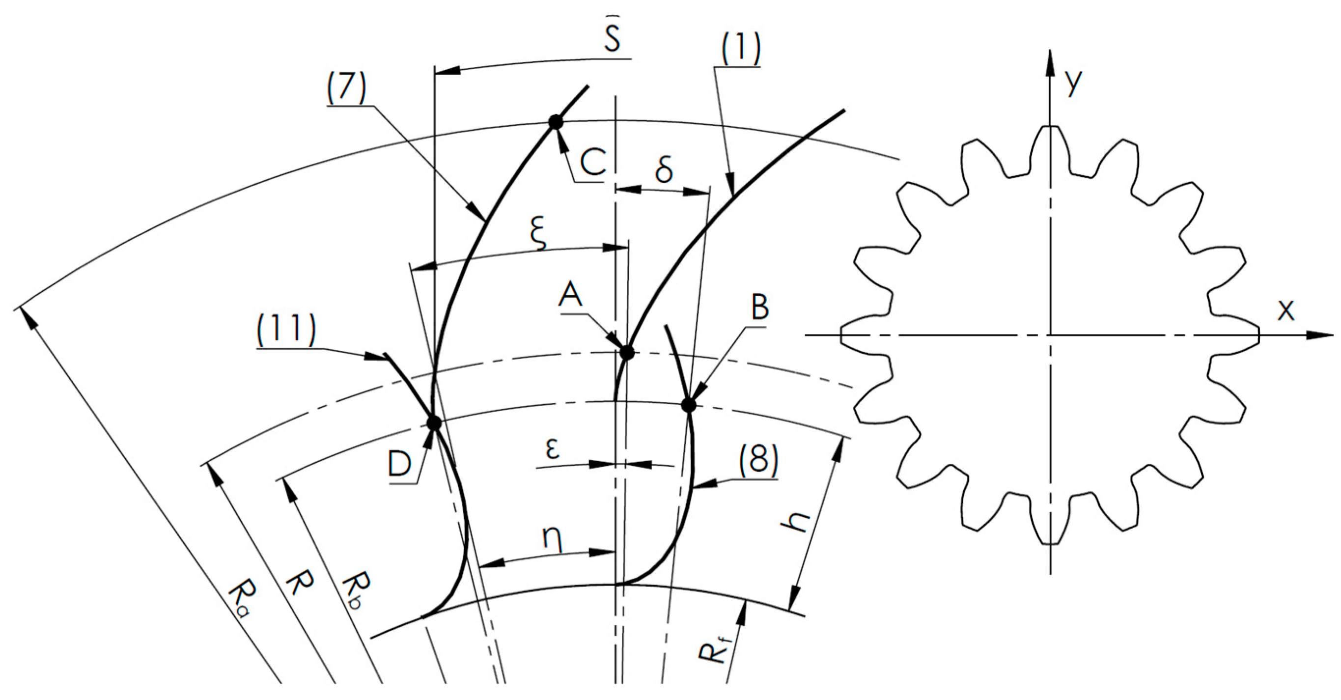
Figure 2.
Schematic of the envelope-based simulation of the shaping process using a rack tool. Where: Rf – root diameter, Ra – tip diameter, R – pitch diameter, ω – angular velocity of the gear, v – linear speed of the cutting tool, ρ – radius of the cutting tool rounding, 1, 2, 3, 4 – successive profiles generated by the tool (magnified).
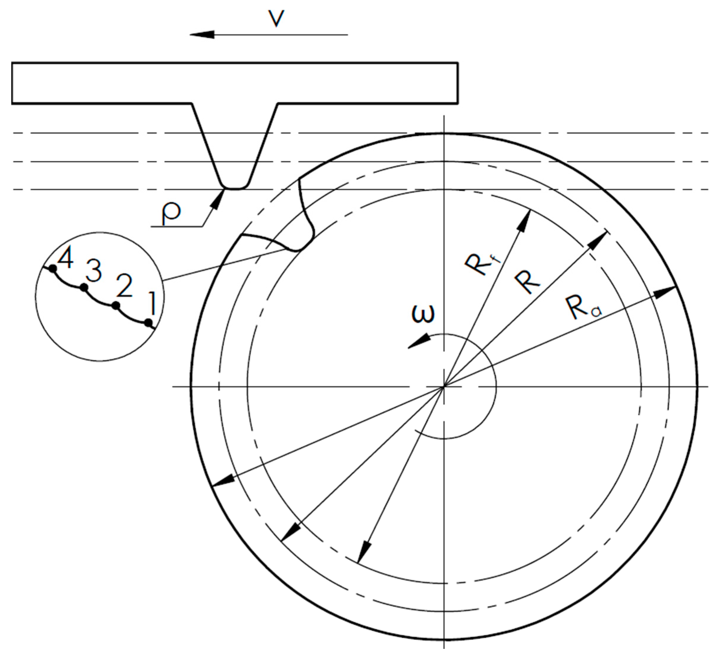
Figure 3.
Comparison of the tooth flank geometry obtained by two methods: a) full view of the tooth flank, b) magnified region showing the transition between the working flank and the root, illustrating convergence of the two modeling methods.
Figure 3.
Comparison of the tooth flank geometry obtained by two methods: a) full view of the tooth flank, b) magnified region showing the transition between the working flank and the root, illustrating convergence of the two modeling methods.
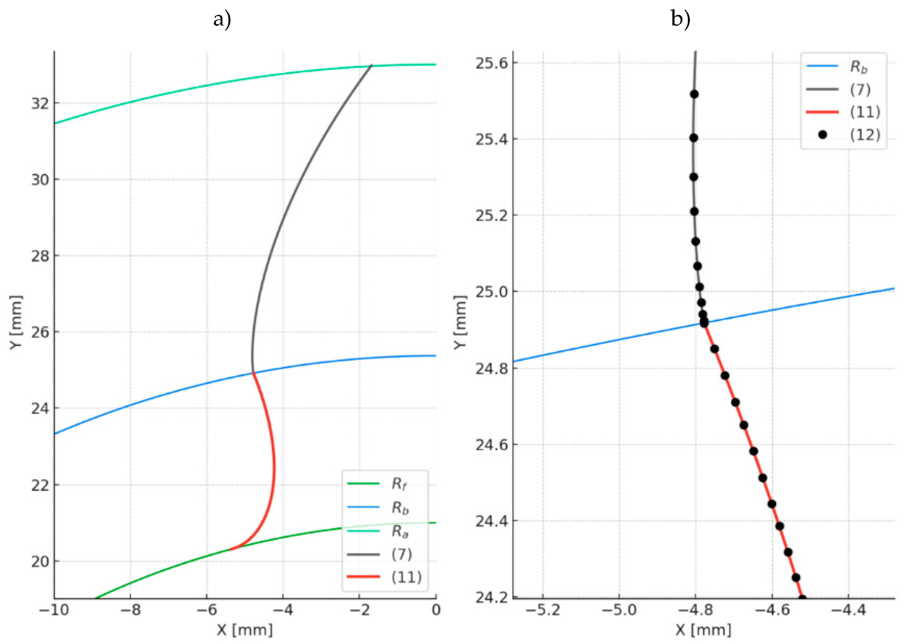
Figure 4.
Schematic of the envelope-based simulation of the broaching process using a rack-type tool. Where: Rt – pitch diameter of the broaching tool, Ra – root diameter of the tooth, R – pitch diameter of the machined gear, ω – angular velocity of the gear, ωt – angular velocity of the broaching tool, ρ – tool tip rounding radius.
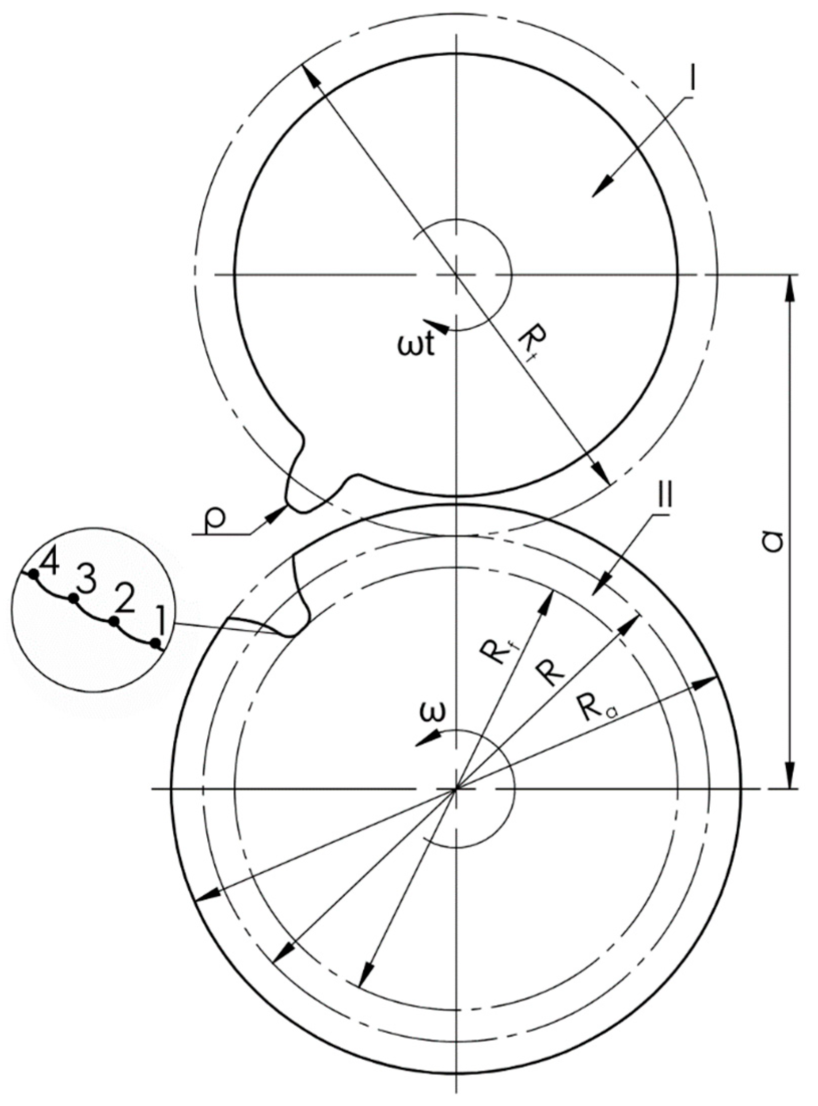
Figure 5.
Comparison of tooth flank geometry obtained using two methods:a – full view of the tooth flank, b – magnified section at the junction of the working flank and root transition curve showing agreement between the two methods.
Figure 5.
Comparison of tooth flank geometry obtained using two methods:a – full view of the tooth flank, b – magnified section at the junction of the working flank and root transition curve showing agreement between the two methods.
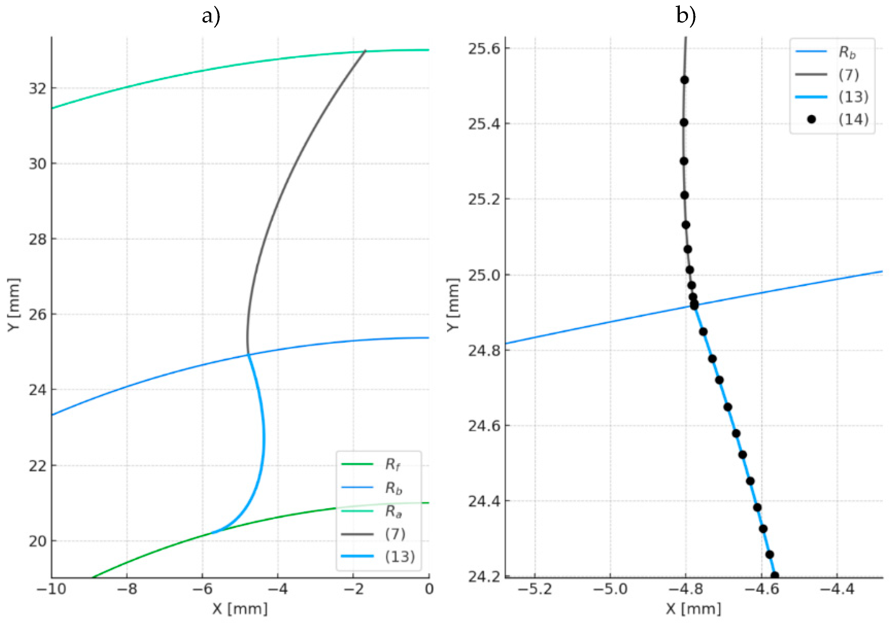
Figure 6.
Geometry difference of the tooth flank obtained via broaching and shaping for the parameters from Table 1.
Figure 6.
Geometry difference of the tooth flank obtained via broaching and shaping for the parameters from Table 1.
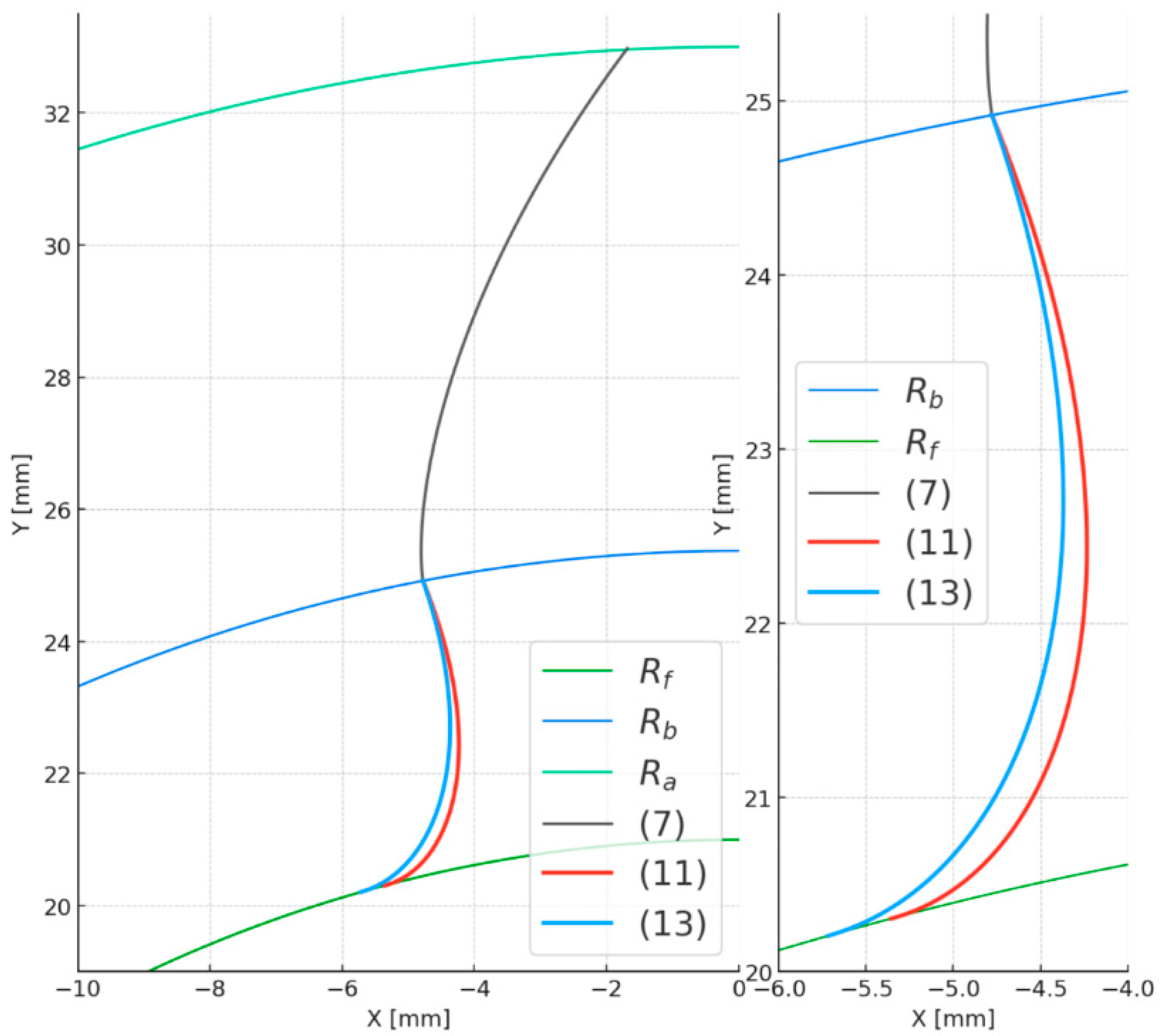
Figure 7.
Schematic for the numerical determination of tooth root stresses.
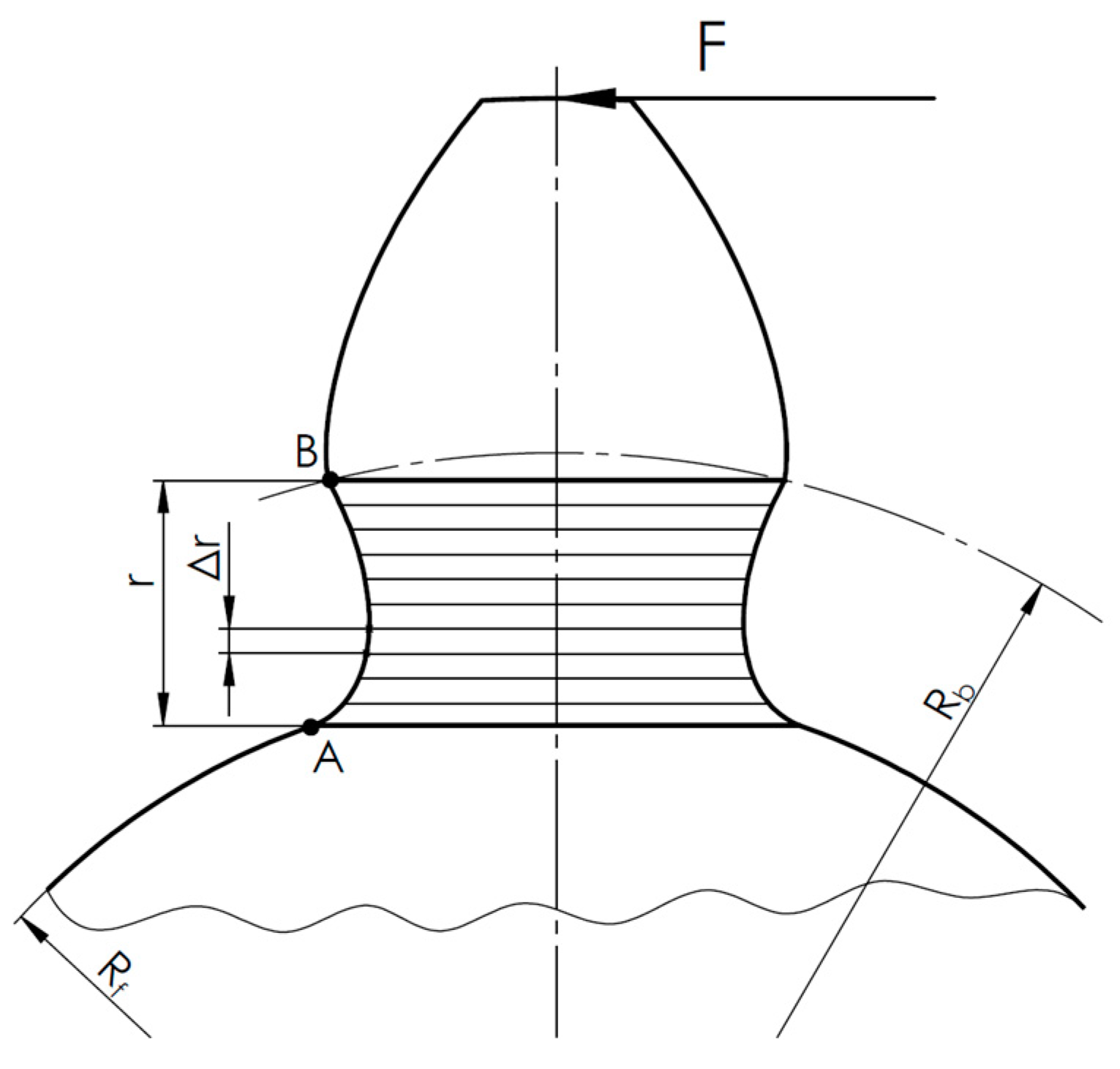
Figure 8.
Comparison of results from FEM and numerical integration method for the shaping-based root curve (extended involute).
Figure 8.
Comparison of results from FEM and numerical integration method for the shaping-based root curve (extended involute).
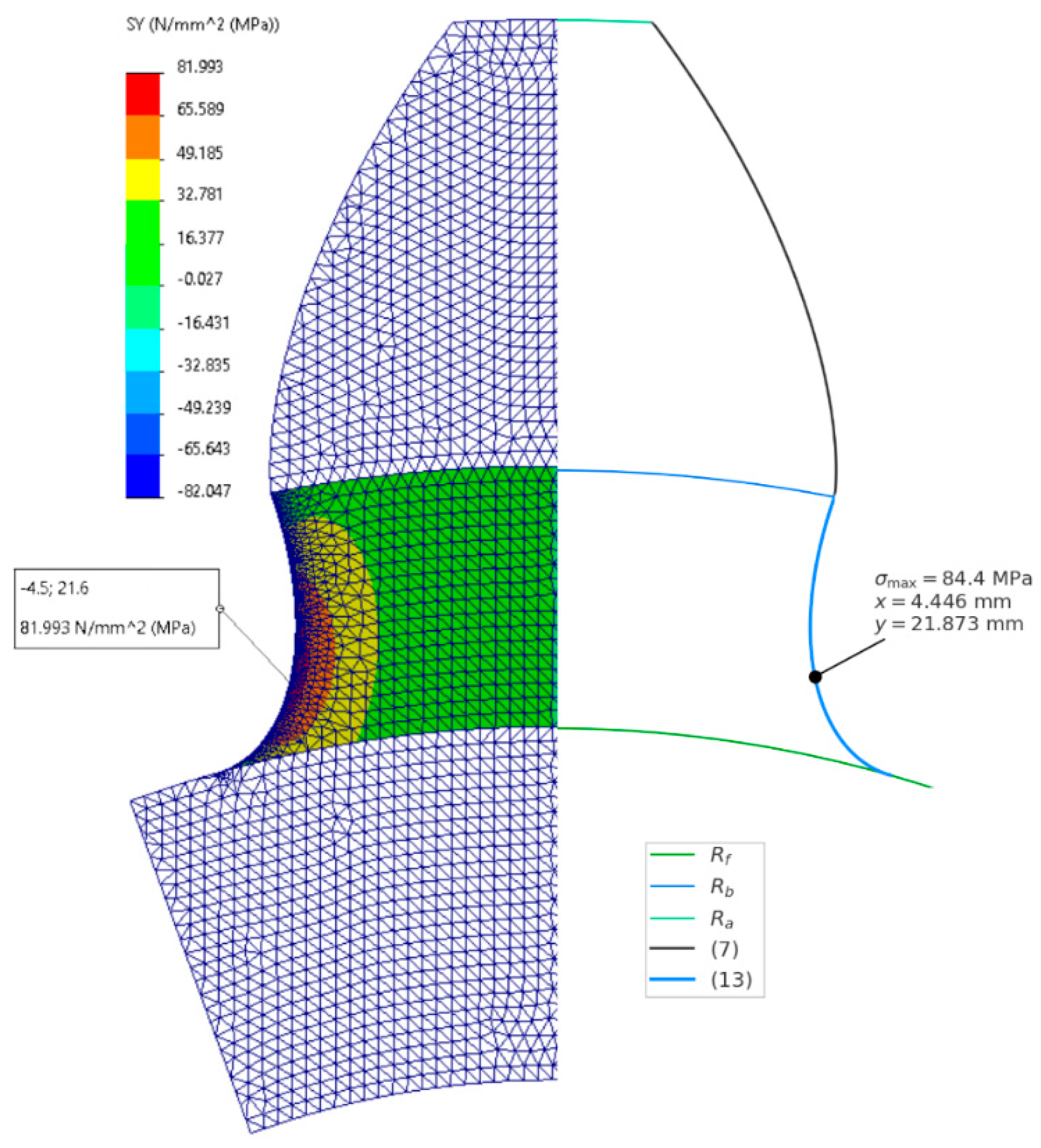
Figure 9.
Comparison of results from FEM and numerical integration method for the broaching-based root curve (epicycloid).
Figure 9.
Comparison of results from FEM and numerical integration method for the broaching-based root curve (epicycloid).
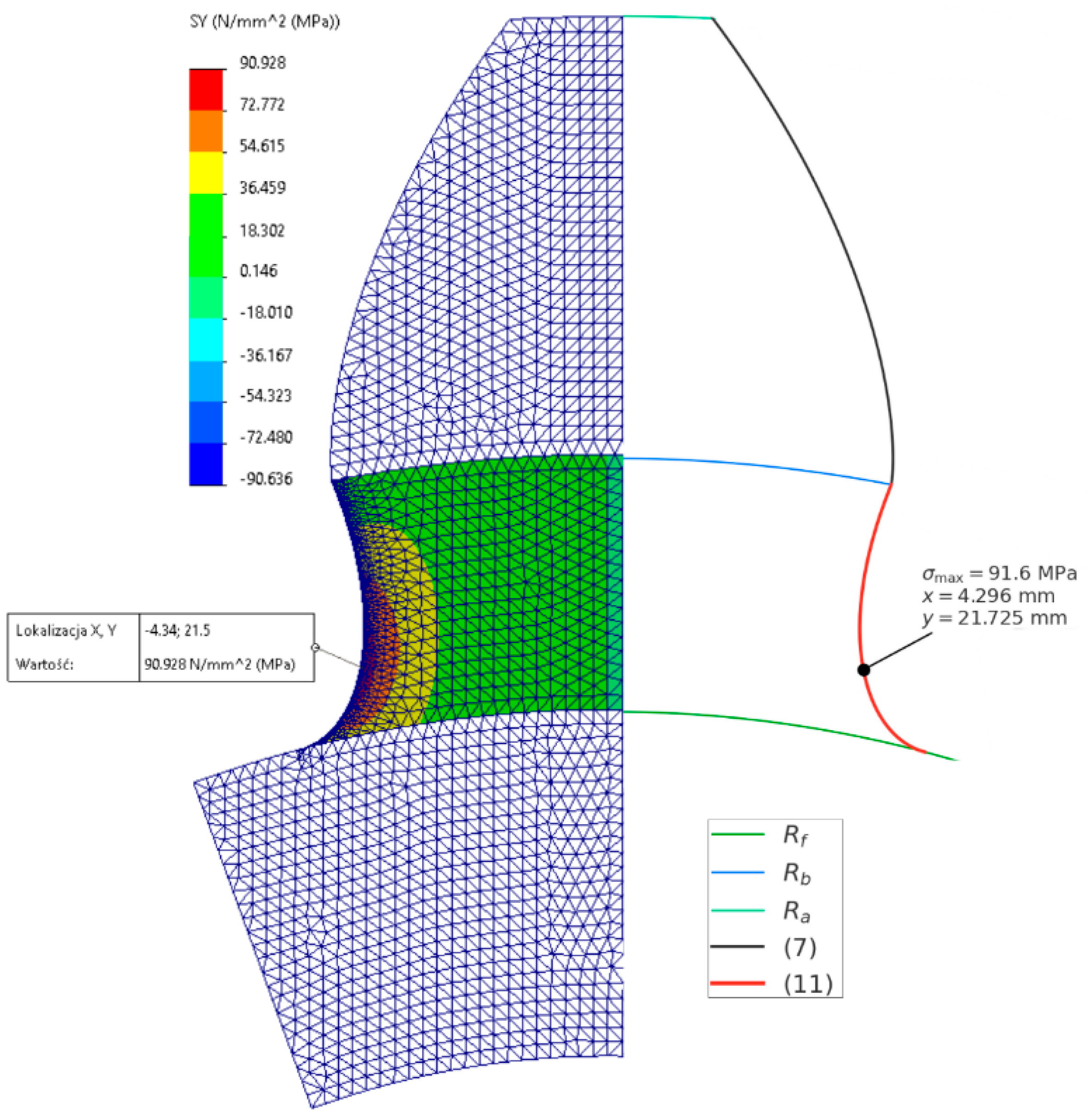
Figure 10.
Plot of the change in root stress values as a function of radius ρ for the shaping method (extended involute).
Figure 10.
Plot of the change in root stress values as a function of radius ρ for the shaping method (extended involute).
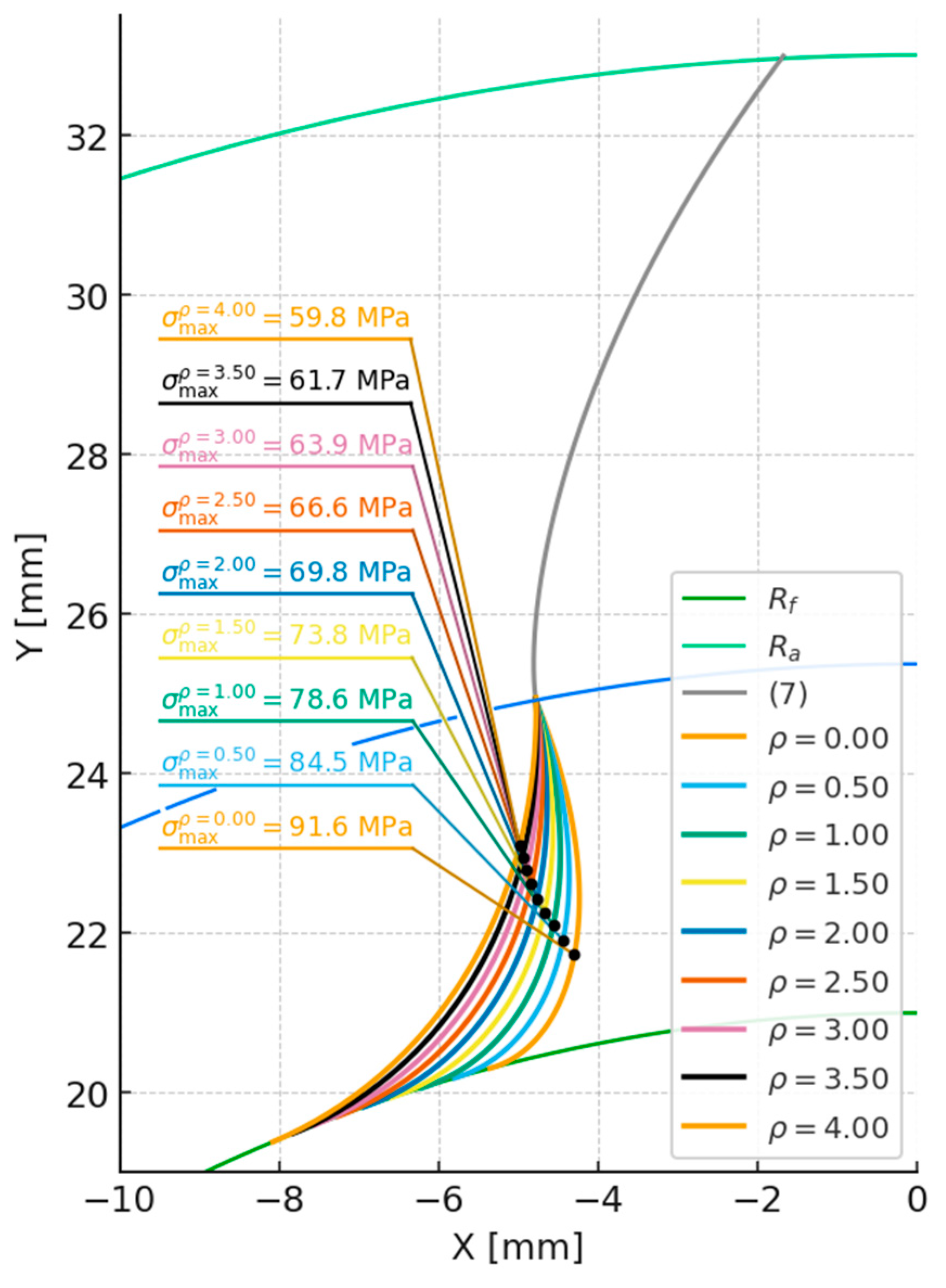
Figure 11.
Plot of the change in root stress values as a function of radius ρ for the broaching method (epicycloid).
Figure 11.
Plot of the change in root stress values as a function of radius ρ for the broaching method (epicycloid).
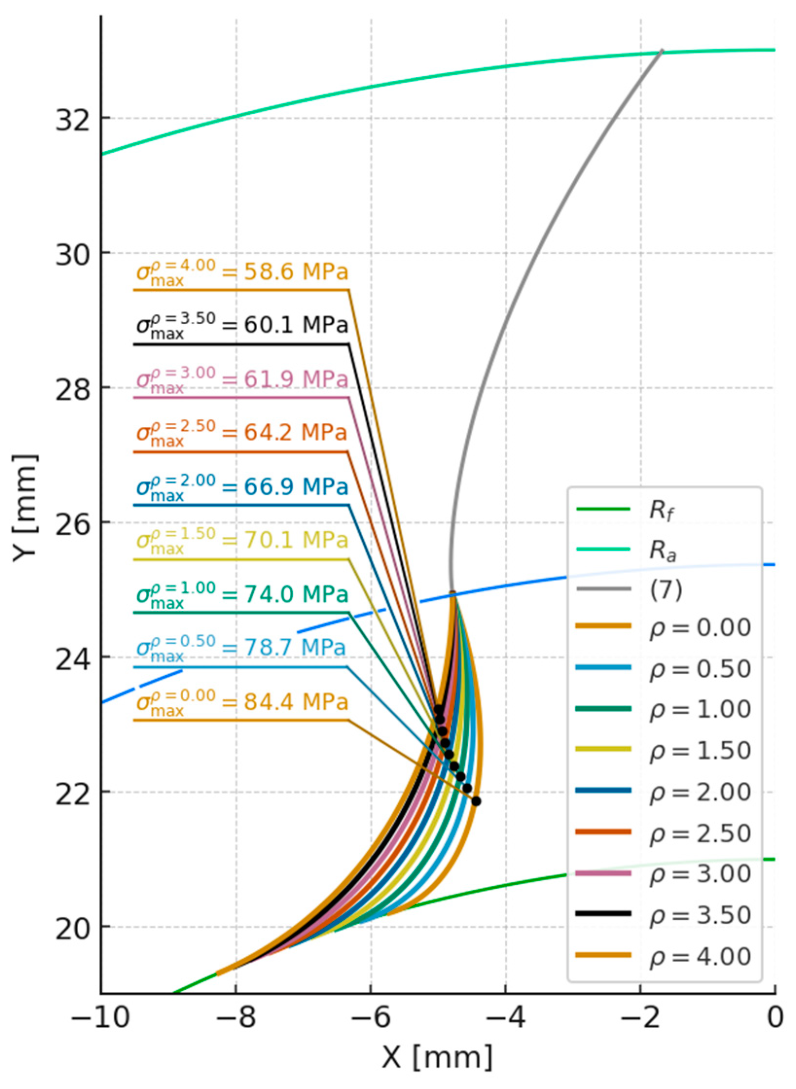
Figure 12.
Maximum stress values for the two machining methods at ρ = 0 mm and z₂ = 6: (11) – extended involute equation, (13) – epicycloid equation.
Figure 12.
Maximum stress values for the two machining methods at ρ = 0 mm and z₂ = 6: (11) – extended involute equation, (13) – epicycloid equation.
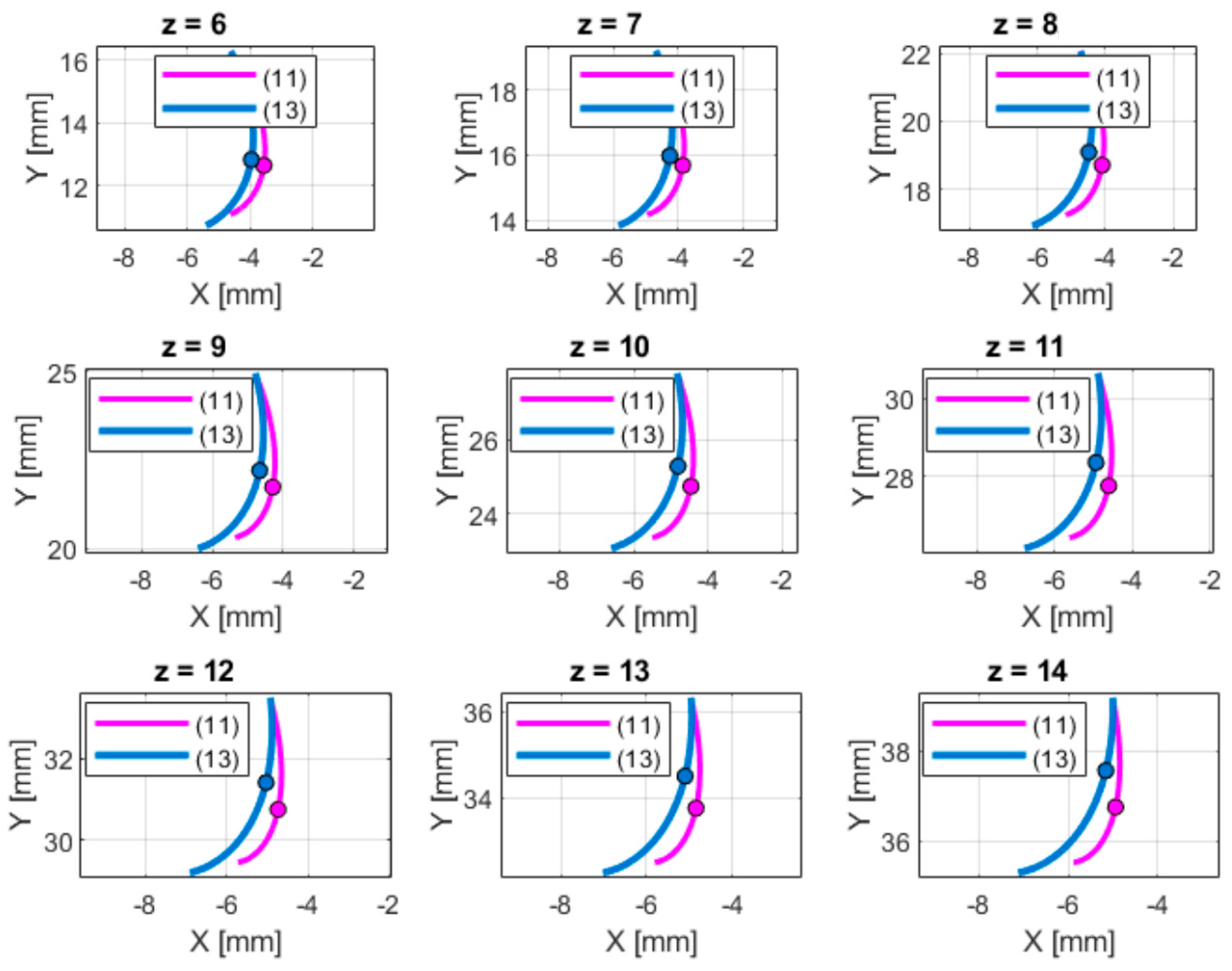
Figure 13.
Maximum stress values for the two machining methods at ρ = 0 mm and z₂ = 54: (11) – extended involute equation, (13) – epicycloid equation.
Figure 13.
Maximum stress values for the two machining methods at ρ = 0 mm and z₂ = 54: (11) – extended involute equation, (13) – epicycloid equation.
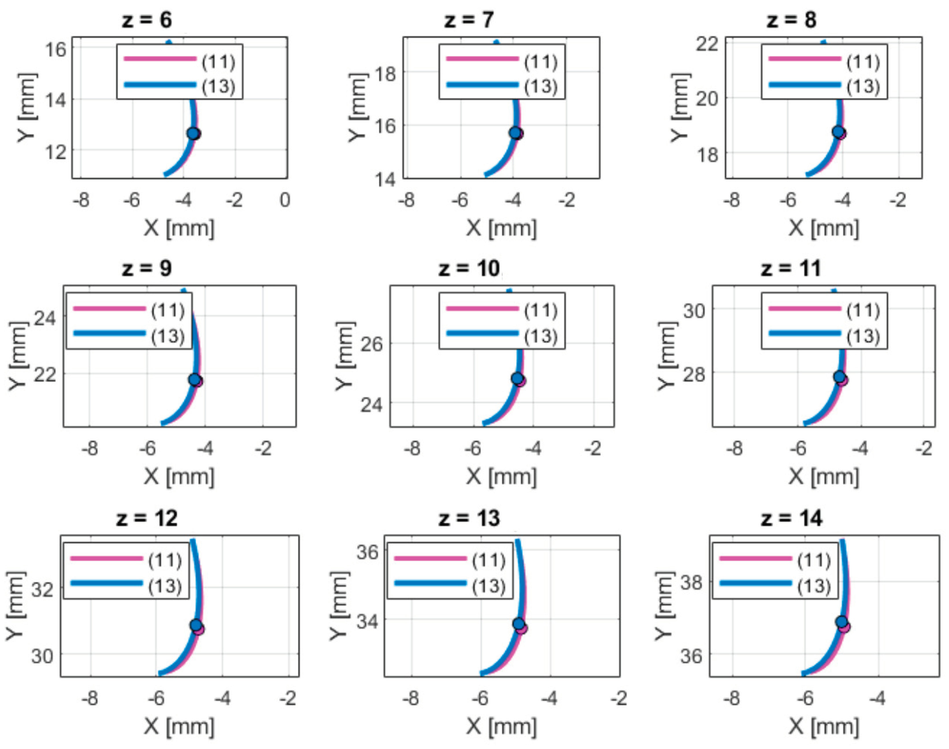

Table 1.
Gear parameters.
| parameter | designation | value |
|---|---|---|
| Module [mm] | m | 6 |
| Number of teeth [-] | z | 9 |
| Tool rounding radius [mm] | ρ | 0 |
| Gear ratio [-] | u | 1 |
Table 2.
FEM parameters for the analyzed models:.
| Parameter | Extended Involute | Epicycloid |
|---|---|---|
| Element size [mm] | 0.25 | |
| Tolerance [mm] | 0.0075 | |
| Total number of nodes [-] | 16443 | 16635 |
| Total number of elements [-] | 7916 | 8008 |
| Jacobian points [-] | 16 | |
| Minimum number of elements per circle [-] | 8 | |
| Element growth rate [-] | 1.4 | |
Table 3.
Differences in tooth root stress values for various ρ values and the two analyzed methods:.
Table 3.
Differences in tooth root stress values for various ρ values and the two analyzed methods:.
| ρ [mm] | σmax (13) [MPa] | σmax (11) [MPa] | Δσ [MPa] | Δσ [%] |
|---|---|---|---|---|
| 0 | 87.797 | 91.625 | 3.827 | 4.18 |
| 0.4 | 82.617 | 85.802 | 3.185 | 3.71 |
| 0.8 | 78.178 | 80.832 | 2.654 | 3.28 |
| 1.2 | 74.37 | 76.585 | 2.215 | 2.89 |
| 1.6 | 71.101 | 72.953 | 1.852 | 2.54 |
| 2.0 | 68.293 | 69.843 | 1.55 | 2.22 |
| 2.4 | 65.88 | 67.18 | 1.299 | 1.93 |
| 2.8 | 63.807 | 64.898 | 1.091 | 1.68 |
| 3.2 | 62.026 | 62.942 | 0.917 | 1.46 |
Table 4.
Percent differences in root stress values between the machining methods (ρ = 0 mm, z₂ = 6).
Table 4.
Percent differences in root stress values between the machining methods (ρ = 0 mm, z₂ = 6).
| z [–] | Δσ [%] | z [–] | Δσ [%] |
|---|---|---|---|
| 6 | 20.43 | 11 | 17.35 |
| 7 | 19.91 | 12 | 16.59 |
| 8 | 19.34 | 13 | 15.77 |
| 9 | 18.72 | 14 | 14.91 |
| 10 | 18.06 |
Table 5.
Percent differences in root stress values between the machining methods (ρ = 0 mm, z₂ = 6).
Table 5.
Percent differences in root stress values between the machining methods (ρ = 0 mm, z₂ = 6).
| z [–] | Δσ [%] | z [–] | Δσ [%] |
|---|---|---|---|
| 6 | 4.13 | 11 | 4.1 |
| 7 | 4.17 | 12 | 4.03 |
| 8 | 4.18 | 13 | 3.94 |
| 9 | 4.18 | 14 | 3.83 |
| 10 | 4.15 |
Disclaimer/Publisher’s Note: The statements, opinions and data contained in all publications are solely those of the individual author(s) and contributor(s) and not of MDPI and/or the editor(s). MDPI and/or the editor(s) disclaim responsibility for any injury to people or property resulting from any ideas, methods, instructions or products referred to in the content. |
© 2025 by the authors. Licensee MDPI, Basel, Switzerland. This article is an open access article distributed under the terms and conditions of the Creative Commons Attribution (CC BY) license (http://creativecommons.org/licenses/by/4.0/).
Copyright: This open access article is published under a Creative Commons CC BY 4.0 license, which permit the free download, distribution, and reuse, provided that the author and preprint are cited in any reuse.


