Submitted:
26 December 2024
Posted:
27 December 2024
You are already at the latest version
Abstract
Recompressed sCO2 Brayton Cycles (RCBC) are topical in the narrative of sustainable energy conversion and are considered to be at 80 % technology readiness level, but still open to thermal efficiency (ηth) and levelized cost of energy (LCOE) enhancements. However, the lack of rigorous academic engagement in the specific nexus of concentrated solar plant (CSP) RCBCs and Triply periodic minimal surface (TPMS) recuperators may be veiling the honey pot. This study surveys data over two decades around academic and research institutions on the history and trends of solar RCBCs and how recuperators contribute to their thermal and economic efficiency. Findings show that many theoretical studies on the RCBC exist, but among RCBC – CSP demonstration plants, there is a total of three (3) ongoing full scale testing stations in the US, EU and China and a couple others still in the construction and initial commissioning stage. The highest reported ηth is 54 % and the lowest LCOE is 0.059 $/kWh. Among the existing test stations worldwide, most use printed circuit heat exchangers (PCHE) recuperators, despite numerical studies presented in this study proving that TPMS recuperators are more effectual on both thermal, hydraulic and LCOE per-formance. As a result, this study has made a strong case in proposing that better prospects may lie around TPMS hybridization of recuperators retrofitted into CSP RCBCs. The authors have strengthened their case by presenting literature evidence on the availability sCO2 compatible alloys, maturity of TPMS manufacturing technology, cost and time effectiveness of their fabrication.

Keywords:
Supercritical CO2
; Triply periodic minimal surface
; Recuperators
; Hybridization
; Levelized cost of energy
1. Introduction
Supercritical carbon dioxide (sCO2) can effectively be applied to heat transfer applications in both high- and low-quality heat source power plants [1]. It requires low work input on compressors [2] because it is high in density but low in both viscosity and compressibility. It is abundant, non-toxic, non-corrosive, non-flammable, non-explosive, of good price (1/70 of R134a [3] and 1/250 of Helium) [4], and environmentally sustainable. In terms critical density, the thermophysical properties of sCO2 trump those of its contenders, making it suitable for advanced energy conversion and generation technologies. Its application will surely help the world in achieving the United Nations sustainable development goals, (SGDs) 7,9 and 13, viz., Affordable and clean energy, Industry, innovation and infrastructure and Climate action. These capabilities of sCO2 promise to appease the universal energy concerns arising from the growing energy demand (1.1 % or 6.6 exajoules, between 2022 and 2013) and the soaring 39.3 billion tons global emissions of CO2 [5]. The intense efforts to find clean and efficient energy conversion technologies are hindered by amongst others the technical bottlenecks of large-scale commercialization and the renewable energy conversion plants’ high investment costs.
The sCO2 Brayton cycle (SCBC) provide high thermal efficiencies, reduces the fuel consumption, lowers the power generation’s impact on the environment, and utilizes compact and modular turbomachinery [6,7]. It can be observed in NIST’s [8] thermophysical properties that the viscosity of sCO2 is lower than in the liquid state, which leads to high compressibility and significantly reduced compressor work [2]. As said by Yaping et al. [3], the critical pressure (Pc) and critical temperature (Tc) (7.3773 MPa and 304.12 K) (Table 1, Figure 1c) of sCO2 allows the power plant to operate under a relatively low pressure, and to use air instead of water as the heat sink. In fact, some studies [4,9,10] have also explored other equally capable fluids, which are still outdone by sCO2, whose special feature is its near ambient critical temperature and low cost.
This study’s scope is in solar RCBCs (with partial cooling, intercooling and reheating) because is outperforms the steam cycle and the SRC (Figure 1a), and the all the other cycles (Figure 1b) in the 450 - 650oC heat source range [11]. Moreover, Guo et al. [12], as seen in Figure 1c, found them to have higher (>1.8%) thermal efficiency improvement against the baseline basic/simple recuperated cycle (SRC). At inlet temperature and pressure of 565 oC and 25 MPa, the simple RCBC improved the efficiency of the SRC by >3.51 %, the partial cooling RCBC (PCC) by >1.98 %, and the inter cooling RCBC (ICC) by > 3.93 %. The reference to RCBCs in this study shall encompass all its variants (PCC, ICC, reheating, preheating), unless the contrary is stated. As shall be seen in later sections of this study, impressive thermodynamic efficiencies of > 45 % have been reported in RCBCs.
Another advantage of the SCBCs is that they have compact sized turbomachinery (e.g. reduced turbine stages due to low pressure ratios) and thermal equipment. The compactness of heat exchangers (HXs) is due to the high sCO2 density throughout the cycle because the minimum working pressure is 7,400 kPa [3]. This compactness provides significant CAPEX savings and space economy. HXs, besides being able to condense sCO2 by convective air currents at the heat sink, the heating curve of sCO2 rises smoothly without a pinch point – a desirable quality.
The cutting edge of research in the compactness and effectiveness of HXs is the application of Triply periodic minimal surface (TPMS) topology design, especially now in the advent of thin-walled materials and 3D printing. Maskery et al [14] acclaims TPMS HXs with high specific surface area, enhanced pore connectivity, versatile applications, while other authors ascribe to them qualities such as high surface area-to-volume ratio [15,16,17], reduced pressure drop [16,18], anti-fouling capacity [19,20,21] and, owing to their increased turbulence; enhanced heat and mass transfer [22]. Of even greater interest lately is the studies that show that TPMS HXs can perform better than the famously used printed circuit HXs (PCHE). The studies around hybridized TPMS HXs are also revolutionizing thermo hydraulic performance metrics.
Given that up to 90 % [23] of the cost of SCBCs could be associated with PCHEs, 30 % being for general HXs [2], strongly beckoning as it may is the question; could there possibly be higher than reported and undiscovered thermal efficiencies and low Levelized Cost of Energy (LCOE) at the nexus of hybridized TPMS recuperators and solar RCBC power plants? How much more when a RCBC’s turbine/(s) discharges its expanded but relatively hot CO2 into an evaporator of a transcritical CO2 cycle (TCC) bottoming cycle? And more – what if the waste heat recovery HX coupling the cycles is a hybridized TPMS HX topology design?
Most studies and reviews lend themselves to the basic operational physics the SCBC, comprehensive comparative performance analysis and optimization between several configurations across all SCBCs, exploration of suitable working fluids, special fields of application, partial or comprehensive key component (turbo machinery and thermal) analysis, and indiscriminate energy source analysis of SCBCs. Form the foregoing summary of existing reviews, the following gaps are apparent;
- There is no review that is specific to solar RCBC various configurations in the renewable energy heat sources. This niche needs deep analysis because it is environmentally sustainable and has high and promising thermal efficiencies [12] with concerted research efforts to lower the concentrated solar power (CSP) side LCOE.
- There is no survey that covers hybrid TPMS HXs within the context of their application to RCBC recuperators.
For this study to be strategically funneled towards a truly sustainable RCBC survey, with lowest plant economics (investment and operational costs) and the lowest environment impact indicators, RCBC technologies reviewed here are of solar heat sources only. Any references to non-renewable heat sources in this study are purely for comparative or contextual purposes. For the same reasons, where this study analyses the recent technologies of RCBC’s combined power plants, it deals only with those whose topping and bottoming cycles’ working fluid/(s) is pure CO2, (unless stated otherwise), hence working fluid mixtures excluded.
After a brief on the operational definition of the RCBC and its efficiency improvement configurations, a brief history of the SCBC is presented. Recent numerical and experimental advances in energy, exergy and economic optimization of the RCBC are reviewed, followed by recent numerical, experimental and test stations of common HX applications in SCBCs. TPMS HXs studies are then introduced, and a discussion is advanced around their possible replacement of PCHE as next generation recuperators. Because high pressure and temperature sCO2 environment is corrosive, material selection, manufacturability and cost considerations are also presented. Lastly, this study concludes by suggesting research and future prospects in the nexus of solar RCBCs and hybrid TPMS HXs, a most needed avant-garde – or not?
2. The Physics of the RCBC
To save this review from a cumbersome and lengthy discourse about the basics, a broader definition, working principle, and classification of CO2 power plants has been done justice by White et al.[24], Tamilarasan et al.[2] and Liu et al.[3] among others, and readers are referred there. It therefore suffices for us to be specific to the working principle of RCBCs, howbeit, a brief on the fundamentals of operation is necessary.
The RCBC Configurations–Efficiencies Improvement
A SCBC is a closed loop cycle (see Figure 2a, Figure 3, and Figure 4a) that has a turbine and a compressor for isentropic expansion and isentropic compression, respectively. It also has HXs. Depending on their function on the cycle, they are either called intercoolers, heaters or recuperators, and they operate at constant pressure. Following Figure 2a, the sCO2 at above critical pressure and temperature is fed into the compressor (1 – 2), after which it is heated (2 – 3) and fed for expansion into the turbine (3 - 4). Exit turbine temperatures are normally decent enough to be channeled to a recuperator to harness its thermal energy (mostly by preheating), and this completes the configuration of a simple recuperated sCO2 cycle. Cooling (4 – 1) can be by air or water. The efficiency of this cycle is not impressive. This section follows through with advanced configuration to improve efficiency. Figure 2b shows a proper P-H diagram of sCO2 with temperature, density and entropy isopleths with the regions labeled versus the perfect gas region.
To increase the efficiency of the SRC, several layouts such as recompression, precompression, inter-cooling, partial cooling and reheating, have been invented and numerically analyzed. Next, we discuss the evolution of the SRC into RCBC variants, which is shown by Figure 3 and accompanying schematics in Figure 4. Figure 3 is focused on compressor centered configurations while Figure 4 demonstrates both expansion and heating configurations. Recompression is used to counter the pinch temperature point effect in the recuperator, and yields even better efficiencies when coupled with reheating. Recompression is when the recuperator is divided into 2; low-temperature recuperator and high temperature recuperator, between which is a compressor, hence the name; recompression cycle, naming one main compressor, the other re-compressor. This reduces heat capacity variation and decreases the mass flow rate in the high-pressure line – which has a significant reduction effect on the pinch temperature effect. Reheating achieves better thermodynamic efficiencies because of higher turbine exit temperatures, which are obtained by dividing the expansion process into two and fitting a heating component in between.
Partial cooling is another RCBC configuration that improves thermodynamic efficiencies. In PCC, sCO2 exiting the low temperature recuperator (LTR) is cooled and compressed in the first stage of the main compressor. After the LTR the sCO2 flow is divided into two; one stream is cooled and recompressed to the high pressure of the cycle before it is preheated in the LTR, whereas the other stream is directly compressed at the high pressure of the cycle and mixed with the stream exiting the LTR [26], where they now proceed as one into the high temperature recuperator (HTR) The other configuration (ICC) is similar to the PCC, except that it has intercooling in the main compression process and no flow separation along its high pressure flow into the LTR. Wang et al. [27], after studying five configurations, concluded that intercooling and partial cooling improves the efficiency of both the precompression and the recompression cycles, which we will quantitatively consider more comprehensively in another section of this study.
3. Brief History of RCBC
The pioneers of real gas investigations in the 19th century were Thomas Andrews and James Thompson who experimented the validity of Boyle’s law across a wide range of pressures [24,28]. However, consideration of CO2 as a working fluid for power generation did not start until 1942, culminating with the registration of a Swiss patent by the Sulzer Bros, of a closed loop CO2 power cycle [29], being a partially cooled condensation process. Dekhtiarev, Feher and Angelino seem to have been technological contemporaries of the CO2 technology development from the early 1960s. Feher investigated the effects of varying operating conditions in simple recuperated sCO2 cycle, and also raised irreversibility issues in the cycle [24]. Angelino then set out to investigate irreversibility reduction among various cycle configurations operating in the supercritical and transcritical states [30,31,32]. It was Angelino who first concluded that the RCBC, at > 650 oC, performed better than the Rankine cycle, and advised that it is suitable for high-temperature heat sources like nuclear.
Dostal, who resuscitated research in this technology in the 21th century, attributes the decades of non-activity to insufficient turbomachinery experience, lack of applicable HXs, and the absence of suitable heat sources [33]. Dostal [4] recommended the RCBC as the best in his comprehensive thermodynamic and economic investigations of intercooling, reheating, precompression and recompression in next generation nuclear reactors. From this foundational work of Dostal, works have expanded to solar, fuel cells, fossil fuel, waste heat [3] and has grown to more than 80 patents (56 % from China alone), and more than 800 academic documents (USA with the most share at 26 %) of research both theoretically and experimentally between 1988 and 2020 [24]. According to Tamilarasan et al. [2], research articles came up to 1300 (12.6 % reviews, 87.4 % research) in 2023, and China leads research efforts, accounting for about 35 % research outputs. Figure 5 shows an example of research progress in the Sandia National Laboratories (SNL), a national security science and engineering lab with many branches in the USA but primarily headquartered in Albuquerque, New Mexico. The next section explores the different test facilities similar to the SNL facility across the world with a bias to CSP projects.
Experimental Facilities of RCBC
Many academic and industrial institutions have developed prototypes to test the practical validity of using sCO2 in power technology. Guo et al. [12], Liu et al. [3] and Marchionni et al. [35] have presented the prototypes around the world according to power outputs, primary heat source and inlet turbine temperatures. Nuclear prototypes were first developed by SNL and Knolls Atomic Power Labs (KAPL) and were then followed by Korea Advanced Institute of Technology (KAIST), Korea Atomic Energy Research Institute (KAERI), Xi’an Jiaotong University and the Harbin Engineering University [36,37,38,39,40,41,42]. The steady state and transient simulations of both KAIST worked on a 36.2 MW 20-year lifetime conceptual design. The Harbin Engineering University simulated safety analysis, dynamic operating conditions and developed a control scheme. In terms of capacity, the Southwest Research Institute (SwRI), General Electric Company (GE), and Thar Energy are developing test loops up to 1 MW, while TIT (Tokyo Institute of Technology), Institute of Applied Energy (IAE), Korea Institute of Energy Research (KIER) and the Bechtel Marine Propulsion are working on the 1 kW to 100 kW range and the KAERI and KAPL are working on greater than 100 kW scale [43,44,45,46,47].
On demonstration projects, research and academic institutions around the world have built and continue to build sCO2 power plants to further investigate the technology gaps and explore commercialization advancements. Table 2 shows the projects in China, the EU and the USA. In Q1 of 2024, Salvaore et al.’s preliminary results of the EU SolarSCO2OL Demonstration Project on enabling the integration of a 2 MW simple Brayton sCO2 power block into a hybrid CSP-PV Plant utilizing heat derived from PTC molten salts reported a thermodynamic efficiency of 22.1% [48]. This is the first EU MW scale facility to couple a high-temperature molten salt PTC (also has a thermal energy storage), called the Evora Molten Salt Platform (EMSP), in Portugal, with a sCO2 power block. Project partners estimate that a similar simple Brayton cycle with analogous component designs will yield an > 30.5 % efficiency at 10 MW scale, and 41.4 % on a reheat recompressed cycle [48]. While the Dunhuang/Shouhang project seem to have attempted demonstrations on their CSP solar tower, but results are not forthcoming.
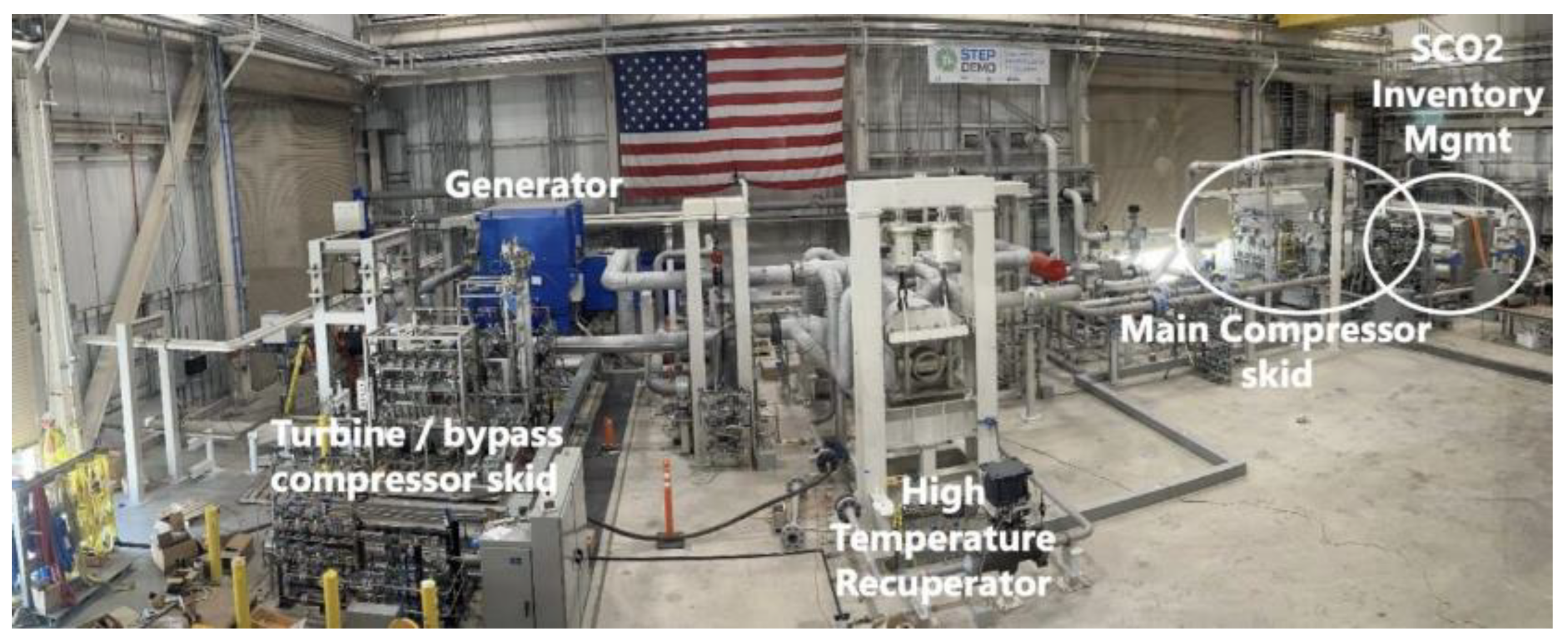
According to Powermag [49], the biggest of the sCO2 demonstration power plants is the Supercritical Transformational Electric Power (STEP) project which began plans for the San Antonio, Texas, USA based plant in 2013. It is led by the Supercritical CO2 Technology Team which is a collaboration between the offices of Nuclear Energy (NE), Fossil Energy (FE) and Energy Efficiency and Renewable Energy (EERE). Its mission is to reduce the technical barriers and risks that delay the commercialization of the sCO2 power cycle [50]. It did not initiate construction until 2018, mechanical completion was in October 2023, commissioning in December 2023 and just completed Phase 1 (on SRC) performance testing in March of 2024. The Phase 1 testing, was on the SRC at full operational turbine speed of 27,000 RPM, operating at turbine inlet temperature (TIT) of 500 oC and 250 bar, yielding 4 MWe of grid-synchronized power. Phase 2 which is scheduled for early 2025 will have TIT of 715 oC, and will be on their RCBC, targeting 10 MW. The HTR is made from 316 stainless steel and is the world’s largest with a PCHE 50 MWt capacity, weighs 50 tons [51]. The natural gas fired heater has a firing capacity of 93 MWt, with a 740H heater coil, and was first fired on-site in September 2023. All the demonstration projects faced supply challenges as components had to be customized. This is an indication that there is ample research work that has to be done on component design.
Figure 6.
The 10-MWe Supercritical Transformational Electric Power (STEP) Demo pilot plant in San Antonio, Texas [49].
Figure 6.
The 10-MWe Supercritical Transformational Electric Power (STEP) Demo pilot plant in San Antonio, Texas [49].
4. RCBC State of the Art Studies
Many studies have been conducted on the RCBC and its efficiency improvement configurations for the purpose of system design, assessment, control, monitoring, improvement, troubleshooting and optimization. Energy (based on the first law) and exergy (based on the second law) modeling are normally used for system performance analysis. Exergy analysis at component level is a key quantitative assessment of energy usefulness, energy loss location, entropy generation, irreversibility, optimum operating conditions that enables maximization of output work [3]. Optimal thermodynamic performance (maximizing thermal/energy/exergy efficiency) and optimal costs (minimizing investment cost or cost of electricity) is achieved by coupling the equation of state of sCO2 and each component’s thermodynamic model [24]. Different cycle parameters are varied within certain constraints and boundaries, to determine how their variation affect the cycle performance. Focus is only on recent solar RCBC’s most advanced configurations of ICC and PCC, some with reheating.
Table 5 shows mass, energy and exergy balances normally used for model development. Thermodynamic energy, exergy and electricity cost results from recent RCBC studies and its related configurations within varying constraints and operating conditions are presented in Table 4. None optimized thermodynamic results without the cost function are in Table 3. Figure 7 shows Project Sunshot’s CSP LCOE 2030 goal.
Modeling of Solar RCBCs
The Sunshot mission projects the LCOE to reach an all time record low of 0.05 USD/kWh by 2030 with approximately 12 hours of storage [52]. This envisaged drop in LCOE and the uptrend of thermal efficiencies of solar driven sCO2 power conversion systems promise a blissful future for sCO2 sustainable energy conversion technology, which can only be limited by amongst other things, the plant components/equipment’s thermal capabilities and as admitted by Guo et al. [12], the working temperature on the CSP side, as is the case presently. LCOE/COE analysis should not be used as the only basis of determining suitable energy conversion technologies. Besides LCOE, researchers have to pursue above-board approaches of determining cycle performance such as comprehensive thermo economic environmental optimization techniques. Abdelghafar et al. [53] expressed a similar sentiment that equipment capital cost, system maintenance, operating cost, and the thermodynamic performance metrics (energy, exergy, etc.) should be coupled in power plants analysis. This approach results in robust models or optimization results that reflect close to true overall cycle performance, and can be trusted to inform decision making. Another noteworthy observation by other authors is that reporting optimal results with the related technological limits, boundary and operating conditions is important.
In the surveyed literature, results vary widely depending on the objective functions and operating conditions, therefore final design considerations and decisions have to be made based on trade-offs of significance to the designer. Summarily, according to Table 3, RCBC energy efficiencies were reported in the range of 23.6 to 51.8 % and while their exergy efficiencies are not well researched/documented in literature, suggesting a knowledge gap. The improved RCBCs with either MC intercooling, reheat, or partial cooling generally show decent energy efficiencies (39.2 – 54%), but low exergy efficiencies (20.5 – 22.9 %). Besides combined cycles, the highest reported energy efficiency is 54 %, on a RCBC with PCC and reheating. A RCBC/TCC combined power cycle recorded an impressive energy efficiency of 46.43 % and an exergy efficiency of 80.59 %. On optimization studies as seen on Table 4, energy efficiency ranges are between 26.3 and 55 %, optimized for LCOE ranges of 0.059 to 0.11 $/kWh. It is not obvious to deduce the best configuration from the current studies as they use different operating conditions, constraints and optimization methodologies, but it is safe to conclude that they generally surpass non-RCBCs, other working fluids, and other power cycles, when taking into consideration their compactness and low LCOEs. Encouraging prospects of CSPs, Abdelghafar et al. [53] have advised that research efforts should continue to be intensified around lowering costs of both CSP plants and related sustainable energy storage strategies. This is especially because the component selectivity analysis findings of Reznicek et al. [54] [21 have identified CSPs as having the highest influence on LCOE.
Should improvements be focused on the components, Sunshot’s commercialization roadmap and target of 0.05 $/kWh should be within reach in the near future. Can the advent of hybridized TPMS recuperators and their application to RCBCs be the alchemy between the now (full scale testing) and commercialization, to the full attainment of the SDGs? Section 5 of this study explores these recuperators.
5. Key Components
To stay true to the topic and scope of this survey, the only key components that will be discussed are those in the interests of this study, the HXs, most specifically the recuperators, as was earlier qualified that they significantly influence overall plant performance. In this section, we hypothisize that if most RCBC are performing well with PCHE, but many studies show that TPMS HXs perform better than PCHE, then retrofitting solar RCBCs with TPMS HXs should be the future, much more with hybridized TPMSs. We will present their development, manufacturability, manufacturing costs, applicable advanced materials to fabricate them, their present and prospective applications to solar RCBCs. For an in depth insight on other sCO2 related key components like turbomarchinery technologies, readers are referred to Marchionni et al. [35], White et al. [24] and Liu et al. [3] amongst others.
Heat Exchangers (Primary Heaters, Recuperators and Coolers)
As stated earlier, the need to innovate around HXs is motivated by the data that up to 90 % [23] of the cost of SCBCs could be associated with PCHEs, 30 % of the cost with general HXs [Saravana], and that recuperator performance is crucial for achieving 46 % system performance in RCBCs. Structural designs of HXs are interventions to improve one or several of the characteristics that improve heat transfer effectiveness and pressure drop. In fact, the many existing innovations are as a result of this pursuit. These structural designs come in the form of HX shape, size, surface area to volume ratio, plate baffles shape/size, fin shapes/ sizes, tube shape/ diameter/ number/ arrangement, surface roughness and direction of flow. Manipulation of these structural features affect operating temperature and pressure range, mass flow rate, pressure drop, heat transfer effectiveness and coefficient, flow velocity, scalability, compactness, modularity, heat duty per unit volume, creep, fouling and fatigue resistance, structural integrity, material shrinkage, material cost, operation maintenance and corrosive attack. The design of HXs is therefore complex and needs detailed numerical analysis and optimization coupled with prototyping and in situ experiments. In most cases, the maximization of one or two features comes at the expense of other/(s), and this can not be avoided, hence a balanced trade off is required, in most cases it is around the triple matrix of economy and/or thermal and/or hydraulic aspects.
In terms of cost per UA unit ($/(kW/K)), studies by Marchionni [71] show that across general applications (primary heaters, recuperators and coolers), PHE as gas coolers are the most economic at 50. The primary heater is known to be energy intensive and [72] agree on a figure above 5000 for shell S&T, Micro tube and PCHEs. The PCHE was found to have a cost per UA unit north of 2500 across general HX application [73], while the Formed Plate HX (FPHE) was about 2000 in the gas cooler and the recuperator.
Applications of HXs to either a primary heater, recuperator or cooler is therefore dependent on which of the said features make the best engineering and economic sense, and White et al.’s [24] narration makes for a good read on that. In primary heaters, PCHE are commonly used where liquid is a heat source, while for a gas heat source, shell and tube (S&T) and micro tube HXs are most suitable. Specific CO2 laminar and turbulent thermal and hydraulic correlations of empirical Nusselt (Nu.) in different cross sections, flow channels and fin shapes are widely dealt with by Tamilarasan et al [2], Guo et al [12], Liu et al. [3], Marchionni et al. [35] and White et al. [24], while we present only the operating parameters of experimental studies in Table 6. Tano and colleagues [74] have recently done an interesting study on sCO2 – molten salt TPMS based HX that the reader may refer to, as we hasten narrowly onto recuperators.
In spite of their pinch point problems, cleaning difficulties, high possibility of fouling, and high pressure drops due to their long flow passages, and complicated channel geometry [24], the high pressure and temperature resistance, creep and fatigue resistance of PCHEs and FPHEs makes them crème de la crème recuperators for SCRCs. However, in the last five years, they seem to be taking a rear seat as technological innovations seem to favour TPMS HXs, Plate Matrix HX (PMHE), the Wire Mesh HX (WMHE), cast metal HXs and microtube HXs with axial separation sheets [75]. The technology of TPMS HXs is actively being numerically and experimentally modelled across a wide range of applications.
A TPMS is a shape that has 2 distinct and intertwined volumes separated by a thin wall. Their design is best illustrated in [15,76]. Examples of some of their shapes appear on Figure 8. A molten salt to sCO2 HX made from a diamond TPMS is demonstrated in Figure 8 by Kelly et al [77]. As mentioned earlier, TPMS HXs have enhanced pore connectivity, versatile applications, while other authors ascribe to them qualities such as high surface area-to-volume ratio [15,16,17], reduced pressure drop [16,18], anti-fouling capacity [19,20,21] and, owing to their increased turbulence; enhanced heat and mass transfer [22]. TPMS HXs numerical models in literature exist around desalination technologies like membrane distillation [75,78,79,80,81,82], phase change materials and thermal energy storage [83,84,85,86], thermal management as in the cooling of batteries to achieve peak battery performance [87], hydrogen storage technology [88], adsorption cooling systems and high power density cooling. However, our study focuses on their application to recuperators, where a fluid stream is cooling another fluid stream, both in single phase.
A study of heat transfer effectiveness and pressure drop by Kim and Yoo [90] found the Diamond topology based HX to perform 100 % better than a PHE on thermal effectiveness. Diamond, together with Gyroid and Primitive HXs, despite their curved complex shapes, matched the pressure drop of PHE. Iyer et al. [91] and Yan et al. [92] both developed friction factor (f) and Nu. correlations of TPMS HXs. The Nu. and the f are as presented in Figure 9 and 10. This laminar flow comparative study on pressure drop and heat transfer among 7 TPMS HXs with a pipe HX as baseline shows that TPMS HXs have better f (up to 13 times better than a pipe). On how the TPMS HXs fared against a normal pipe based HX on Nu., the Diamond and C(I2-Y) are the highest due to intermittent ebb and flow regime that is caused by the topologies’ internal disturbance structure. Iyer and colleagues also concluded that to remove the same amount of heat and operate under the same pressure conditions, the Schwarz-D based HX was 3 – 10 times smaller (more compact) than a tubular HX.
On the performance evaluation coefficient (PEC), the PCHE was outperformed 90 – 100 % by Diamond, Gyroid and IWP (I-graph and wrapped package-graph) as seen on Figure 10 [92]. PEC is the ratio between Nu (Nu/Nu0) and friction factor (f/f0)1/3, both dimensionless. Li et al. [93], on the cooling of sCO2 using Gyroid and Diamond HXs, proved better results than on a PCHE. A 29 % improved thermal effectiveness on a Brayton sCO2 cooler was recorded by Liang et al [94], better than on the PCHE. Yan et al. [95] concluded that hybridizing primitive and gyroid with diamond enhanced both heat transfer and pressure drop.
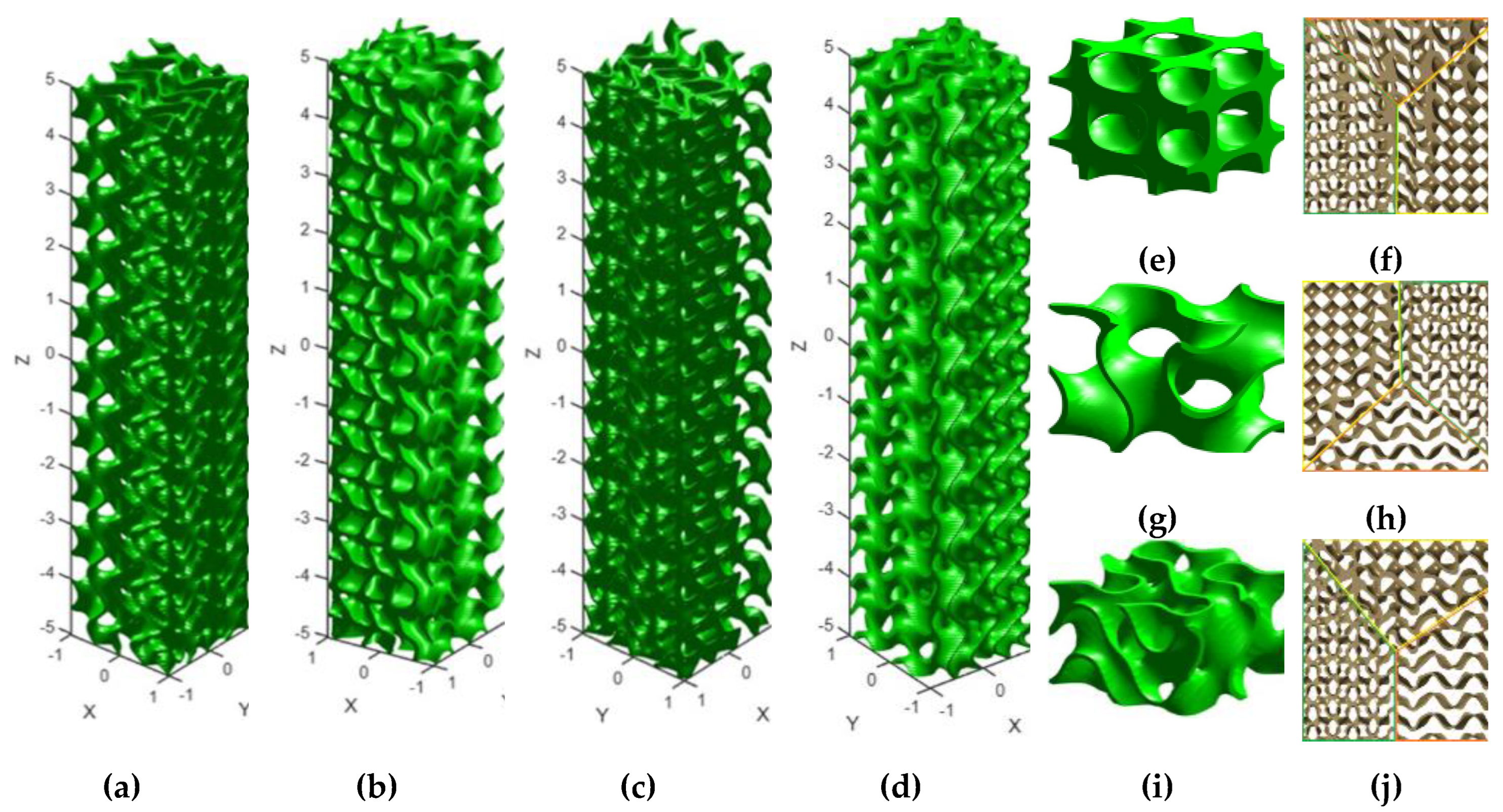
In general, the superior performance of TPMS based HXs is highly attributable to their high mixing and homogenization patterns, bifurcation flow pattern, high surface area to volume ratio and early (Re = ~300) turbulent flow development. In closing this section, we need to speak to the non-existence of studies on TPMS HX on RCBC, and the need to merge the individual typologies (hybridize) to study if putting together individual typologies into one HX (hybridization) yields superior results. This follows from the logic that typologies may complement each other’s thermohydraulic weaknesses when hybridized. The hybridization methodology is comprehensively presented by Yang et al. [115] and Al Ketan and Abu Al Rub [76]. The only hybridization works related to heat trasfer, though not in RCBCs, are by Letlhare-Wastikc [116] and Yang [115] and Yan et al. [95]. Yan et al. studied area goodness factor (j/f), pressure drop and heat transfer effectiveness in 2 typology TPMS hybrids. Their study established that that the factor is better in standard TPMSs than in 2 TPMS based hybrid TPMSs. This is interesting as one would expect the hybridization to improve HX performance. These studies need to be continued on other fluids. Their study concluded that hybridizing primitive with diamond or gyroid with diamond enhanced both heat transfer and pressure drop, but overall, pressure drop of standard TPMSs was still lower than of the hybrids. We propose strongly that further studies on HX TPMS hybridization, even up to three typologies on RCBCs, need to be performed.
Figure 12.
The (a), (b), (c), (d) developed hybrid HX in 4 views by merging (e) diamond, (g) gyroid and (i) FKS and (f), (h), (j) The cross sections of the hybrid TPMS [116].
Figure 12.
The (a), (b), (c), (d) developed hybrid HX in 4 views by merging (e) diamond, (g) gyroid and (i) FKS and (f), (h), (j) The cross sections of the hybrid TPMS [116].
6. Materials, Cost and Manufacturability of TPMS HXs
When selecting a recuperator material for high temperature and pressure operating conditions within industrial applications, it is important to consider the material’s thermal and mechanical properties because in sCO2 environment, as admitted by Badescu et al.[117] and Li et al.[118], corrosion, oxidation, carburization, decarburisation and creep resistance are important factors worthy of consideration. Another important consideration is the manufacturing method, throughput, and fabrication and maintenance costs [119]. This section will discuss the latest research on the manufacturability of TPMS HXs, the suitability of materials and the cost implications of 3D manufacturing. The objective of this section is not so much about reviewing structural and thermal studies of AM manufactured TPMSs, but to demonstrate that should RCBCs advance to incorporating TPMS recuperators, the materials and the technology to manufacture TPMS structures exists within cost effective measures.
6.1. Materials
Survey studies covering materials which are normally used for AM can be found in [120,121,122,123]. Studies have been conducted on temperatures ranging from 400 oC to 800 oC, pressures from 0.1 to 30 MPa and hours of operation between 194 hours and 8,000 hours in Ferritic martensitic steels (FM), Austenitic steels, oxide dispersion strengthened steels (ODS), Iron based alloys and Nickel based alloys. Alloys commonly applied to recuperators are AlSi10Mg, CuCrZr, X5CrNi18-10, Alloy 800HT, M380, SUS304, and SS316L. These studies identified that in FM steels and Austenitic steels, the rate of oxide scale formation is directly proportional to time. For across the board general sCO2 environment applications, researchers propose advanced doping techniques to improve the poor oxidation resistance in FM steels, and carburization (caused by high pressures) which is also prominent among them. Oxidation resistance and carburization in Austenitic steels are better than in FM steels, and pressure and thermal cycling have been shown to have insignificant effect on oxidation. These studies focused oxidation and carburization studies on 316FR, 800H, Al-6XN, 316SS, and 310SS. Even though ODS is known to be costly, it is reported to display no carburization under the oxide scale, with impressive corrosion resistance.
6.2. Manufacturability
The technology of additive manufacturing (AM), has matured into a space of producing uniform, functionally graded and hybrid TPMSs according to Al-ketan et al. [15,17], implying with less fabrication costs, better customization, improved resolution, lightweight designs, low cost for prototyping, sustainability benefits, reduced fabrication time. The reader may refer to [15,26,76,83,124] for a comprehensive review of the AM technologies for TPMS.
As regards TPMS manufacturability that can be applied to TPMS recuperators, techniques such as Fused Deposition Modeling (FDM), Digital light processing (DLP), Selective laser sintering (SLS), Microstereolithography/SLA and Two photon polymerization (2PP). Without going into their descriptions, merits and demerits, these techniques have been applied across the board on the fabrication of ceramic, metallic and alloyic TPMSs with AM resolutions varying from 15 micrometers to more than 300 micrometers. The SLA has been used to fabricate gyroid diamond and primitive TPMSs. The primitive TPMS has been fabricated by 2PP, SLA, FDM and DLP [60,89,125]
A cost analysis study on the two most promising 3D printing technologies was conducted by Cramer et al. [119], comparing extrusion-based (EB) and binder jet (BJ) 3D-printing-based AM technologies followed by phenolic PIP and silicon infiltration for ceramic HXs, placed BJ at US$0.011 and EB at US$0.1322, being capital cost per cubic inch. This level of manufacturing cost in terms of cubic were unimaginable in the last two decades.
Additive manufacturing and advanced alloying technology have significantly transformed manufacturing time, cost, and customization of light weight, compact and high surface area to volume ratio HXs over the last two decades. This advancement is an unprecedented epoch in the sustainable energy generation industry. Should research efforts be intensified around TPMS recuperator solar RCBC’s, energy, environmental, and social development related SDGs may be engendered sooner than ever imagined.
7. Conclusions
This study reviewed recent studies of the solar RCBCs, and whether the hybrid TPMS HX is utilized on either one of the three kinds of HXs (primary heater, recuperator or cooler). It was established that many theoretical studies on the RCBC exist, but among RCBC – CSP demonstration plants, there is a total of three (3) ongoing full scale testing stations in the US, EU and China and a couple others still in the construction and initial commissioning stage. Among the existing test stations worldwide, and the numerical analysis, most use PCHE recuperators, despite numerical studies presented in this study proving that TPMS HXs are more effectual on both thermal, hydraulic and LCOE performance. As a result, this study has proposed the need to study the effects of TPMS typology hybridization in solar RCBC recuperators, and to the total RCBC power block. In terms of materials and manufacturability of the said TPMS HXs, we have demonstrated that should RCBCs advance to incorporating TPMS recuperators, the materials and the technology to manufacture TPMS structures exists within cost effective measures, but that should be proceeded by numerical analysis, experimenting and prototyping.
Prospectively, despite the commercialization scaling challenges, technology gaps faced by CSP-sCO2 power plants as ably articulated in Moliere et al., CSP’s high LCOE (relative to solar PV), we may as well brace ourselves for lower LCOEs, advanced thermal efficiencies, greener and economic power plants in the next decade if researchers focus their efforts of CSP RCBCs power plants with hybrid TPMSs, highly efficient smaller sized solar collector fields and compact thermal-energy storage technologies. It will take concerted technical collaborations between funders, technical and academic institutions around the world to make CSP RCBC hybrid TPMS recuperated power plants a reality. National energy policies have to be aligned with promoting sustainable energy conversion practices through regulatory guidelines, supporting research funding for leveraging AI and machine learning in exploring and adopting advanced solar RCBC and TPMS technologies.
Future research is crucial for exploring parameters not addressed in this study, such as the application of hybrid TPMSs in the next generation primary heater (sCO2/Molten salt), phase change materials, gas cooler and in turbo machinery designs. As heat sources are predominantly unstable, control strategies need to be developed for uniform process operation and control.
Author Contributions
Conceptualization, K.L.W.; methodology, K.L.W.; software, X.Y.; validation, K.L.W.; formal analysis, X.Y. and K.L.W.; investigation, K.L.W.; resources, X.Y.; data curation, K.L.W.; writing—original draft preparation, K.L.W.; writing—review and editing, X.Y. and K.L.W.; visualization, K.L.W.; supervision, X.Y.; project administration, X.Y. All authors have read and agreed to the published version of the manuscript.
Funding
Please add: This research received no external funding.
Data Availability Statement
Data will be made available on request by emailing the corresponding author.
Conflicts of Interest
The authors declare no conflicts of interest.
References
- Zhang, F.; Zhu, Y.; Li, C.; Jiang, P. Thermodynamic optimization of heat transfer process in thermal systems using CO₂ as the working fluid based on temperature glide matching. Energy 2018, 151, 376–386. [Google Scholar] [CrossRef]
- Tamilarasan, S. K.; et al. Recent Developments in Supercritical CO₂-Based Sustainable Power Generation Technologies. Energy 2024, 17, 64019. [Google Scholar] [CrossRef]
- Liu, Y.; Wang, Y.; Huang, D. Supercritical CO₂ Brayton cycle: A state-of-the-art review. Energy 2019. [Google Scholar] [CrossRef]
- Dostal, V.; Driscoll, M. J.; Hejzlar, P. Advanced Nuclear Power Technology Program. 2004. Available online: http://web.mit.edu/canes/.
- The Energy Institute. In partnership with Statistical Review of World Energy 2023 | 72nd edition, 2023.
- Xu, J.; Wang, X.; Sun, E.; Li, M. Economic comparison between sCO₂ power cycle and water-steam Rankine cycle for coal-fired power generation system. Energy Convers. Manag. 2021, 238, 114150. [Google Scholar] [CrossRef]
- Yousef, M. S.; Santana, D. Thermodynamic and exergoeconomic optimization of a new combined cooling and power system based on supercritical CO₂ recompression Brayton cycle. Energy Convers. Manag. 2023, 295, 117592. [Google Scholar] [CrossRef]
- Huber, M. L.; Lemmon, E. W.; Bell, I. H.; McLinden, M. O. The NIST REFPROP Database for Highly Accurate Properties of Industrially Important Fluids. Ind. Eng. Chem. Res. 2022, 61, 15449–15472. [Google Scholar] [CrossRef] [PubMed]
- Angelino, G.; Invernizzi, C. Real gas Brayton cycles for organic working fluids. Proc. Inst. Mech. Eng. Part A: J. Power Energy 2001, 215, 27–38. [Google Scholar] [CrossRef]
- Rovira, A.; Muñoz-Antón, J.; Montes, M. J.; Martínez-Val, J. Optimization of Brayton cycles for low-to-moderate grade thermal energy sources. Energy 2013, 55, 403–416. [Google Scholar] [CrossRef]
- Gary, R. E.; Rashdan, A. Supercritical CO₂ Direct Cycle Gas Fast Reactor (SC-GFR) Concept.
- Guo, J. Q.; et al. A systematic review of supercritical carbon dioxide (S-CO₂) power cycle for energy industries: Technologies, key issues, and potential prospects. Energy Convers. Manag. 2022. [Google Scholar] [CrossRef]
- Lewis, T. G.; Parma, E. J.; Wright, S. A.; Vernon, M. E.; Fleming, D. D.; Rochau, G. E. Sandia’s Supercritical CO₂ Direct Cycle Gas Fast Reactor (SC-GFR) Concept. In ASME 2011 Small Modular Reactors Symposium; ASME, 2011; pp. 91–94. [CrossRef]
- Maskery, I.; et al. Insights into the mechanical properties of several triply periodic minimal surface lattice structures made by polymer additive manufacturing. Polymer (Guildf.) 2018, 152, 62–71. [Google Scholar] [CrossRef]
- Al-Ketan, O.; Abu Al-Rub, R. K. Multifunctional Mechanical Metamaterials Based on Triply Periodic Minimal Surface Lattices. Adv. Eng. Mater. 2019. [Google Scholar] [CrossRef]
- Li, W.; Yu, G.; Yu, Z. Bioinspired heat exchangers based on triply periodic minimal surfaces for supercritical CO₂ cycles. Appl. Therm. Eng. 2020, 179, 115686. [Google Scholar] [CrossRef]
- Torquato, S.; Donev, A. Minimal surfaces and multifunctionality. Proc. R. Soc. Lond. A 2004, 460, 1849–1856. [Google Scholar] [CrossRef]
- Dharmalingam, L. K.; Aute, V.; Ling, J. Review of Triply Periodic Minimal Surface (TPMS) Based Heat Exchanger Designs. Int. Refrig. Air Cond. Conf. Purdue 2022. Available online: https://docs.lib.purdue.edu/iracc.
- Çulfaz, P. Z.; et al. Fouling Behavior of Microstructured Hollow Fiber Membranes in Dead-End Filtrations: Critical Flux Determination and NMR Imaging of Particle Deposition. Langmuir 2011, 27, 1643–1652. [Google Scholar] [CrossRef] [PubMed]
- Çulfaz, P. Z.; Wessling, M.; Lammertink, R. G. H. Fouling behavior of microstructured hollow fiber membranes in submerged and aerated filtrations. Water Res. 2011, 45, 1865–1871. [Google Scholar] [CrossRef] [PubMed]
- Çulfaz, P. Z.; Haddad, M.; Wessling, M.; Lammertink, R. G. H. Fouling behavior of microstructured hollow fibers in cross-flow filtrations: Critical flux determination and direct visual observation of particle deposition. J. Memb. Sci. 2011, 372, 210–218. [Google Scholar] [CrossRef]
- Lord, E. Periodic Minimal Surfaces of Cubic Symmetry. Curr. Sci. 2003, 85, 346–362, Available online: http://eprints.bbk.ac.uk/policies.html. [Google Scholar]
- Fleming, D.; Pasch, J.; Conboy, T.; Carlson, M. Testing Platform and Commercialization Plan for Heat Exchanging Systems for SCO₂ Power Cycles. In Volume 8: Supercritical CO₂ Power Cycles; Wind Energy; Honors and Awards; ASME, 2013. [CrossRef]
- White, M. T.; Bianchi, G.; Chai, L.; Tassou, S. A.; Sayma, A. I. Review of supercritical CO₂ technologies and systems for power generation. Appl. Therm. Eng. 2021. [Google Scholar] [CrossRef]
- Molière, M.; Privat, R.; Jaubert, J. N.; Geiger, F. Supercritical CO₂ Power Technology: Strengths but Challenges. Energies 2024, 17, 5129. [Google Scholar] [CrossRef]
- Padilla, R. V.; Soo Too, Y. C.; Benito, R.; Stein, W. Exergetic analysis of supercritical CO₂ Brayton cycles integrated with solar central receivers. Appl. Energy 2015, 148, 348–365. [Google Scholar] [CrossRef]
- Wang, K.; Li, M.-J.; Guo, J.-Q.; Li, P.; Liu, Z.-B. A systematic comparison of different S-CO₂ Brayton cycle layouts based on multi-objective optimization for applications in solar power tower plants. Appl. Energy 2018, 212, 109–121. [Google Scholar] [CrossRef]
- Rowlinson, J. S. The work of Thomas Andrews and James Thomson on the liquefaction of gases. Notes Rec. R. Soc. Lond. 2003, 57, 143–159. [Google Scholar] [CrossRef]
- Sulzer, G. Verfahren zur erzeugung von arbeit aus warme. Swiss Patent 269599 1950.
- Angelino, G. Real Gas Effects in Carbon Dioxide Cycles. In ASME 1969 Gas Turbine Conference and Products Show; ASME, 1969. [CrossRef]
- Angelino, G. Carbon Dioxide Condensation Cycles For Power Production. J. Eng. Power 1968, 90, 287–295. [Google Scholar] [CrossRef]
- Angelino, G. Perspectives for the Liquid Phase Compression Gas Turbine. J. Eng. Power 1967, 89, 229–236. [Google Scholar] [CrossRef]
- Yu, A.; Su, W.; Lin, X.; Zhou, N. Recent trends of supercritical CO₂ Brayton cycle: Bibliometric analysis and research review. Nucl. Eng. Technol. 2021, 53, 699–714. [Google Scholar] [CrossRef]
- Mendez, C. M.; Rochau, G. sCO₂ Brayton Cycle: Roadmap to sCO₂ Power Cycles NE Commercial Applications. 2018. Available online: https://classic.ntis.gov/help/order-methods/.
- Marchionni, M.; Bianchi, G.; Tassou, S. A. Review of supercritical carbon dioxide (sCO₂) technologies for high-grade waste heat to power conversion. Springer Nature 2020. [Google Scholar] [CrossRef]
- Kim, S. G.; et al. A concept design of supercritical CO₂ cooled SMR operating at isolated microgrid region. Int. J. Energy Res. 2017, 41, 512–525. [Google Scholar] [CrossRef]
- Jung, H.-Y.; Lee, J. I.; Wi, M.-H.; Ahn, H. J. An investigation of sodium–CO₂ interaction byproduct cleaning agent for SFR coupled with S-CO₂ Brayton cycle. Nucl. Eng. Des. 2016, 297, 158–165. [Google Scholar] [CrossRef]
- Eoh, J.-H.; No, H. C.; Lee, Y.-B.; Kim, S.-O. Potential sodium–CO₂ interaction of a supercritical CO₂ power conversion option coupled with an SFR: Basic nature and design issues. Nucl. Eng. Des. 2013, 259, 88–101. [Google Scholar] [CrossRef]
- Li, M.-J.; Xu, J.-L.; Cao, F.; Guo, J.-Q.; Tong, Z.-X.; Zhu, H.-H. The investigation of thermo-economic performance and conceptual design for the miniaturized lead-cooled fast reactor composing supercritical CO₂ power cycle. Energy 2019, 173, 174–195. [Google Scholar] [CrossRef]
- Li, M.-J.; Jie, Y.-J.; Zhu, H.-H.; Qi, G.-J.; Li, M.-J. The thermodynamic and cost-benefit-analysis of miniaturized lead-cooled fast reactor with supercritical CO₂ power cycle in the commercial market. Prog. Nucl. Energy 2018, 103, 135–150. [Google Scholar] [CrossRef]
- Kim, S. G.; Cho, S.; Yu, H.; Kim, Y.; Jeong, Y. H.; Lee, J. I. System Design of a Supercritical CO₂ cooled Micro Modular Reactor. 2014.
- Yu, H.; Hartanto, D.; Oh, B. S.; Lee, J. I.; Kim, Y. Neutronics and Transient Analyses of a Supercritical CO₂-cooled Micro Modular Reactor (MMR). Energy Procedia 2017, 131, 21–28. [Google Scholar] [CrossRef]
- Cho, J.; et al. The 5th International Symposium-Supercritical CO₂ Power Cycles RESEARCH ON THE DEVELOPMENT OF A SMALL-SCALE SUPERCRITICAL CARBON DIOXIDE POWER CYCLE EXPERIMENTAL TEST LOOP.
- Ahn, Y.; Lee, J.; Kim, S. G.; Lee, J. I.; Cha, J. E. The Design Study of Supercritical Carbon Dioxide Integral Experiment Loop. In Volume 8: Supercritical CO₂ Power Cycles; Wind Energy; Honors and Awards; ASME, 2013. [CrossRef]
- Wright, S.; Conboy, T.; Radel, R.; Rochau, G. Modeling and experimental results for condensing supercritical CO₂ power cycles. Albuquerque, NM, and Livermore, CA (United States), 2011. [CrossRef]
- Clementoni, E. M.; Cox, T. L.; Sprague, C. P. Startup and Operation of a Supercritical Carbon Dioxide Brayton Cycle. In Volume 8: Supercritical CO₂ Power Cycles; Wind Energy; Honors and Awards; ASME, 2013. [CrossRef]
- Utamura, M.; et al. Demonstration of Supercritical CO₂ Closed Regenerative Brayton Cycle in a Bench Scale Experiment. In Volume 3: Cycle Innovations; Education; Electric Power; Fans and Blowers; Industrial and Cogeneration; ASME, 2012; pp. 155–164. [CrossRef]
- Guccione, S. Candidate; Guedez, R. Senior Researcher; Sánchez, Á. R.; Aranda, J. L.; Ruiz, A. Preliminary Results of the EU SolarSCO₂OL Demonstration Project: Enabling the Integration of Supercritical CO₂ Power Blocks into Hybrid CSP-PV Plants. Available online: http://www.emsp.uevora.pt/.
- Breakthrough for sCO₂ Power Cycle as STEP Demo Completes Phase 1 of 10 MW Project. Available online: https://www.powermag.com/breakthrough-for-sco2-power-cycle-as-step-demo-completes-phase-1-of-10-mw-project/.
- Sandia National Laboratories. Supercritical Transformational Electric Power (STEP) Nuclear Energy. Available online: https://energy.sandia.gov/programs/nuclear-energy/advanced-energy-conversion/supercritical-transformational-electric-power-step-nuclear-energy/.
- A Step Forward for sCO₂ Power Cycles; Modern Power Systems. Available online: https://www.modernpowersystems.com/analysis/a-step-forward-for-sco2-power-cycles-11423286/?cf-view&cf (accessed on 8 December 2024).
- Murphy, C.; Sun, Y.; Cole, W.; Maclaurin, G.; Turchi, C.; Mehos, M. The Potential Role of Concentrating Solar Power within the Context of DOE’s 2030 Solar Cost Targets. 2030. Available online: www.nrel.gov/publications (accessed on 8 December 2024).
- Abdelghafar, M. M.; Hassan, M. A.; Kayed, H. Comprehensive analysis of combined power cycles driven by sCO2-based concentrated solar power: Energy, exergy, and exergoeconomic perspectives. Energy Convers. Manag. 2024, 301, 118046. [Google Scholar] [CrossRef]
- Reznicek, E. P.; Neises, T.; Braun, R. J. Optimization and techno-economic comparison of regenerators and recuperators in sCO2 recompression Brayton cycles for concentrating solar power applications. Solar Energy 2022, 238, 327–340. [Google Scholar] [CrossRef]
- Zhao, H.; Deng, Q.; Zheng, K.; Zhang, H.; Feng, Z. Numerical Investigation on the Flow Characteristics of a Supercritical CO2 Centrifugal Compressor. In Volume 3B: Oil and Gas Applications; Organic Rankine Cycle Power Systems; Supercritical CO2 Power Cycles; Wind Energy; American Society of Mechanical Engineers: New York, NY, USA, 2014. [CrossRef]
- Chacartegui, R.; Muñoz de Escalona, J. M.; Sánchez, D.; Monje, B.; Sánchez, T. Alternative cycles based on carbon dioxide for central receiver solar power plants. Appl. Therm. Eng. 2011, 31, 872–879. [Google Scholar] [CrossRef]
- Sun, E.; Xu, J.; Li, M.; Li, H.; Liu, C.; Xie, J. Synergetics: The cooperative phenomenon in multi-compressions S-CO2 power cycles. Energy Convers. Manag. X 2020, 7, 100042. [Google Scholar] [CrossRef]
- Ehsan, M. M.; Duniam, S.; Guan, Z.; Gurgenci, H.; Klimenko, A. Seasonal variation on the performance of the dry cooled supercritical CO2 recompression cycle. Energy Convers. Manag. 2019, 197, 111865. [Google Scholar] [CrossRef]
- Binotti, M.; Astolfi, M.; Campanari, S.; Manzolini, G.; Silva, P. Preliminary assessment of sCO2 cycles for power generation in CSP solar tower plants. Appl. Energy 2017, 204, 1007–1017. [Google Scholar] [CrossRef]
- Singh, H.; Mishra, R. S. Energy- and exergy-based performance evaluation of solar powered combined cycle (recompression supercritical carbon dioxide cycle/organic Rankine cycle). Clean Energy 2018, 2, 140–153. [Google Scholar] [CrossRef]
- Turchi, C. S.; Ma, Z.; Neises, T. W.; Wagner, M. J. Thermodynamic Study of Advanced Supercritical Carbon Dioxide Power Cycles for Concentrating Solar Power Systems. J. Sol. Energy Eng. 2013, 135, 4024030. [Google Scholar] [CrossRef]
- Kouta, A.; Al-Sulaiman, F.; Atif, M.; Bin Marshad, S. Entropy, exergy, and cost analyses of solar driven cogeneration systems using supercritical CO2 Brayton cycles and MEE-TVC desalination system. Energy Convers. Manag. 2016, 115, 253–264. [Google Scholar] [CrossRef]
- Le Moullec, Y.; et al. SHOUHANG-EDF 10MWE SUPERCRITICAL CO2 CYCLE + CSP DEMONSTRATION PROJECT. In Conference Proceedings of the European sCO2 Conference; DuEPublico - Duisburg-Essen Publications Online, 2019; pp. 138–147. [CrossRef]
- Alsagri, A. S.; Chiasson, A.; Gadalla, M. Viability Assessment of a Concentrated Solar Power Tower with a Supercritical CO2 Brayton Cycle Power Plant. J. Sol. Energy Eng. 2019, 141, 4043515. [Google Scholar] [CrossRef]
- Schmitt, J.; Wilkes, J.; Allison, T.; Bennett, J.; Wygant, K.; Pelton, R. Lowering the Levelized Cost of Electricity of a Concentrating Solar Power Tower with a Supercritical Carbon Dioxide Power Cycle. In Volume 9: Oil and Gas Applications; Supercritical CO2 Power Cycles; Wind Energy; American Society of Mechanical Engineers: New York, NY, USA, 2017. [CrossRef]
- Crespi, F.; Sánchez, D.; Rodríguez, J. M.; Gavagnin, G. A thermo-economic methodology to select sCO2 power cycles for CSP applications. Renew. Energy 2020, 147, 2905–2912. [Google Scholar] [CrossRef]
- Wang, G.; Dong, B.; Chen, Z. Design and behaviour estimate of a novel concentrated solar-driven power and desalination system using S–CO2 Brayton cycle and MSF technology. Renew. Energy 2021, 176, 555–564. [Google Scholar] [CrossRef]
- Wang, K.; Li, M.-J.; Guo, J.-Q.; Li, P.; Liu, Z.-B. A systematic comparison of different S-CO2 Brayton cycle layouts based on multi-objective optimization for applications in solar power tower plants. Appl. Energy 2018, 212, 109–121. [Google Scholar] [CrossRef]
- Zhu, H.-H.; Wang, K.; He, Y.-L. Thermodynamic analysis and comparison for different direct-heated supercritical CO2 Brayton cycles integrated into a solar thermal power tower system. Energy 2017, 140, 144–157. [Google Scholar] [CrossRef]
- Neises, T.; Turchi, C. Supercritical carbon dioxide power cycle design and configuration optimization to minimize levelized cost of energy of molten salt power towers operating at 650 °C. Solar Energy 2019, 181, 27–36. [Google Scholar] [CrossRef]
- Marchionni, M.; Bianchi, G.; Karvountzis-Kontakiotis, A.; Pesyridis, A.; Tassou, S. A. An appraisal of proportional integral control strategies for small scale waste heat to power conversion units based on Organic Rankine Cycles. Energy 2018, 163, 1062–1076. [Google Scholar] [CrossRef]
- Bianchi, G.; et al. Design of a high-temperature heat to power conversion facility for testing supercritical CO2 equipment and packaged power units. Energy Procedia 2019, 161, 421–428. [Google Scholar] [CrossRef]
- Marchionni, M.; Bianchi, G.; Karvountzis-Kontakiotis, A.; Pesyridis, A.; Tassou, S. A. An appraisal of proportional integral control strategies for small scale waste heat to power conversion units based on Organic Rankine Cycles. Energy 2018, 163, 1062–1076. [Google Scholar] [CrossRef]
- Tano, I. N.; et al. A Scalable Compact Additively Manufactured Molten Salt to Supercritical Carbon Dioxide Heat Exchanger for Solar Thermal Application. J. Sol. Energy Eng. 2024, 146, 1. [Google Scholar] [CrossRef]
- Chordia, L.; Portnoff, M. A.; Green, E. High Temperature Heat Exchanger Design and Fabrication for Systems with Large Pressure Differentials. Pittsburgh, PA, and Morgantown, WV, USA, 2017. [CrossRef]
- Al-Ketan, O.; Abu Al-Rub, R. K. MSLattice: A free software for generating two-dimensional and three-dimensional lattice structures. Comput. Phys. Commun. 2020, 254, 107447. [Google Scholar] [CrossRef]
- Kelly, J. P.; et al. Binder jet additive manufacturing of ceramic heat exchangers for concentrating solar power applications with thermal energy storage in molten chlorides. Addit. Manuf. 2022, 56, 102937. [Google Scholar] [CrossRef]
- Termpiyakul, P.; Jiraratananon, R.; Srisurichan, S. Heat and mass transfer characteristics of a direct contact membrane distillation process for desalination. Desalination 2005, 177, 133–141. [Google Scholar] [CrossRef]
- Yun, Y.; Ma, R.; Zhang, W.; Fane, A. G.; Li, J. Direct contact membrane distillation mechanism for high concentration NaCl solutions. Desalination 2006, 188, 251–262. [Google Scholar] [CrossRef]
- Lawson, K. W.; Lloyd, D. R. Membrane distillation. J. Memb. Sci. 1997, 124, 1–25. [Google Scholar] [CrossRef]
- Alkhudhiri, A.; Darwish, N.; Hilal, N. Membrane distillation: A comprehensive review. Desalination 2012, 287, 2–18. [Google Scholar] [CrossRef]
- Thomas, N.; Mavukkandy, M. O.; Loutatidou, S.; Arafat, H. A. Membrane distillation research & implementation: Lessons from the past five decades. Sep. Purif. Technol. 2017, 189, 108–127. [Google Scholar] [CrossRef]
- Qureshi, Z. A.; Al-Omari, S. A. B.; Elnajjar, E.; Al-Ketan, O.; Al-Rub, R. A. On the effect of porosity and functional grading of 3D printable triply periodic minimal surface (TPMS) based architected lattices embedded with a phase change material. Int. J. Heat Mass Transf. 2022, 183, 122111. [Google Scholar] [CrossRef]
- Kumaresan, V.; Chandrasekaran, P.; Nanda, M.; Maini, A. K.; Velraj, R. Role of PCM based nanofluids for energy efficient cool thermal storage system. Int. J. Refrigeration 2013, 36, 1641–1647. [Google Scholar] [CrossRef]
- Gado, M. G.; Hassan, H. Energy-saving potential of compression heat pump using thermal energy storage of phase change materials for cooling and heating applications. Energy 2023, 263, 126046. [Google Scholar] [CrossRef]
- Gado, M. G.; Ookawara, S.; Nada, S.; Hassan, H. Performance investigation of hybrid adsorption-compression refrigeration system accompanied with phase change materials − Intermittent characteristics. Int. J. Refrigeration 2022, 142, 66–81. [Google Scholar] [CrossRef]
- Zhao, C.; et al. Multiscale construction of bifunctional electrocatalysts for long-lifespan rechargeable zinc–air batteries. Adv. Funct. Mater. 2020, 30, 2003619. [Google Scholar] [CrossRef]
- Zhao, C.; et al. Multiscale construction of bifunctional electrocatalysts for long-lifespan rechargeable zinc–air batteries. Adv. Funct. Mater. 2020, 30, 2003619. [Google Scholar] [CrossRef]
- Dixit, T.; Al-Hajri, E.; Paul, M. C.; Nithiarasu, P.; Kumar, S. High performance, microarchitected, compact heat exchanger enabled by 3D printing. Appl. Therm. Eng. 2022, 210, 118339. [Google Scholar] [CrossRef]
- Kim, J.; Yoo, D.-J. 3D printed compact heat exchangers with mathematically defined core structures. J. Comput. Des. Eng. 2020, 7, 527–550. [Google Scholar] [CrossRef]
- Iyer, J.; Moore, T.; Nguyen, D.; Roy, P.; Stolaroff, J. Heat transfer and pressure drop characteristics of heat exchangers based on triply periodic minimal and periodic nodal surfaces. Appl. Therm. Eng. 2022, 209, 118192. [Google Scholar] [CrossRef]
- Yan, K.; Wang, J.; Li, L.; Deng, H. Numerical investigation into thermo-hydraulic characteristics and mixing performance of triply periodic minimal surface-structured heat exchangers. Appl. Therm. Eng. 2023, 230, 120748. [Google Scholar] [CrossRef]
- Li, W.; Li, W.; Yu, Z. Heat transfer enhancement of water-cooled triply periodic minimal surface heat exchangers. Appl. Therm. Eng. 2022, 217, 119198. [Google Scholar] [CrossRef]
- Liang, D.; Yang, K.; Gu, H.; Chen, W.; Chyu, M. K. The effect of unit size on the flow and heat transfer performance of the ‘Schwartz-D’ heat exchanger. Int. J. Heat Mass Transf. 2023, 214, 124367. [Google Scholar] [CrossRef]
- Yan, G.; et al. Experimental study on flow and heat transfer performance of triply periodic minimal surface structures and their hybrid form as disturbance structure. Int. Commun. Heat Mass Transfer 2023, 147, 106942. [Google Scholar] [CrossRef]
- Bae, S. J.; Kwon, J.; Kim, S. G.; Son, I. W.; Lee, J. I. Condensation heat transfer and multi-phase pressure drop of CO2 near the critical point in a printed circuit heat exchanger. Int. J. Heat Mass Transf. 2019, 129, 1206–1221. [Google Scholar] [CrossRef]
- Kim, I. H.; No, H. C. Thermal hydraulic performance analysis of a printed circuit heat exchanger using a helium-water test loop and numerical simulations. Appl. Therm. Eng. 2011, 31, 4064–4073. [Google Scholar] [CrossRef]
- Baik, S.; Kim, S. G.; Lee, J.; Lee, J. I. Study on CO2–water printed circuit heat exchanger performance operating under various CO₂ phases for S-CO₂ power cycle application. Appl. Therm. Eng. 2017, 113, 1536–1546. [Google Scholar] [CrossRef]
- Ngo, T. L.; Kato, Y.; Nikitin, K.; Ishizuka, T. Heat transfer and pressure drop correlations of microchannel heat exchangers with S-shaped and zigzag fins for carbon dioxide cycles. Exp. Therm. Fluid Sci. 2007, 32, 560–570. [Google Scholar] [CrossRef]
- Nikitin, K.; Kato, Y.; Ngo, L. Printed circuit heat exchanger thermal-hydraulic performance in supercritical CO2 experimental loop. Int. J. Refrigeration 2006, 29, 807–814. [Google Scholar] [CrossRef]
- Tsuzuki, N.; Kato, Y.; Ishiduka, T. High performance printed circuit heat exchanger. Appl. Therm. Eng. 2007, 27, 1702–1707. [Google Scholar] [CrossRef]
- Pidaparti, S. R.; Anderson, M. H.; Ranjan, D. Experimental investigation of thermal-hydraulic performance of discontinuous fin printed circuit heat exchangers for supercritical CO2 power cycles. Exp. Therm. Fluid Sci. 2019, 106. [Google Scholar] [CrossRef]
- Ding, M.; Li, Y.; Zhou, J.; Zhang, X.; Ma, Z.; Liu, Q.; Wang, Y.; He, Y.; Sun, S.; Zhang, D. An Adaptive Flow Path Regenerator Used in Supercritical Carbon Dioxide Brayton Cycle. Appl. Therm. Eng. 2018, 138, 513–522. [Google Scholar] [CrossRef]
- Zhao, J.W.; Zhao, R.; Le Nian, Y.; Cheng, W.L. Experimental Study of Supercritical CO₂ in a Vertical Adaptive Flow Path Heat Exchanger. Appl. Therm. Eng. 2021, 188, 116597. [Google Scholar] [CrossRef]
- Liu, S.H.; Huang, Y.P.; Wang, J.F.; Liu, R.L. Experimental Study on Transitional Flow in Straight Channels of Printed Circuit Heat Exchanger. Appl. Therm. Eng. 2020, 181, 115950. [Google Scholar] [CrossRef]
- Liu, S.H.; Huang, Y.P.; Wang, J.F.; Liu, R.L.; Zang, J.G. Experimental Study of Thermal-Hydraulic Performance of a Printed Circuit Heat Exchanger with Straight Channels. Int. J. Heat Mass Transfer 2020, 160, 120109. [Google Scholar] [CrossRef]
- Cheng, K.; Zhou, J.; Huai, X.; Guo, J. Experimental Exergy Analysis of a Printed Circuit Heat Exchanger for Supercritical Carbon Dioxide Brayton Cycles. Appl. Therm. Eng. 2021, 192, 116882. [Google Scholar] [CrossRef]
- Zhou, J.; Cheng, K.; Huai, X.; Guo, J.; Zhang, H.; Li, Z. Test Platform and Experimental Test on 100 kW Class Printed Circuit Heat Exchanger for Supercritical CO₂ Brayton Cycle. Int. J. Heat Mass Transfer 2020, 148, 118540. [Google Scholar] [CrossRef]
- Cheng, K.; Zhou, J.; Zhang, H.; Huai, X.; Guo, J. Experimental Investigation of Thermal-Hydraulic Characteristics of a Printed Circuit Heat Exchanger Used as a Pre-Cooler for the Supercritical CO₂ Brayton Cycle. Appl. Therm. Eng. 2020, 171, 115116. [Google Scholar] [CrossRef]
- Zhang, H.; Xu, Z.; Zhao, X.; Li, J.; Sun, H.; Chen, L.; Liu, C.; Cheng, S.; Wang, J. Experimental and Numerical Investigations of Thermal-Hydraulic Characteristics in a Novel Airfoil Fin Heat Exchanger. Int. J. Heat Mass Transfer 2021, 175, 121333. [Google Scholar] [CrossRef]
- Chu, W.X.; Li, X.H.; Ma, T.; Chen, Y.T.; Wang, Q. Experimental Investigation on SCO₂-Water Heat Transfer Characteristics in a Printed Circuit Heat Exchanger with Straight Channels. Int. J. Heat Mass Transfer 2017, 113, 184–194. [Google Scholar] [CrossRef]
- Li, X.H.; Deng, T.R.; Ma, T.; Ke, H.B.; Wang, Q.W. A New Evaluation Method for Overall Heat Transfer Performance of Supercritical Carbon Dioxide in a Printed Circuit Heat Exchanger. Energy Convers. Manag. 2019, 193, 99–105. [Google Scholar] [CrossRef]
- Katz, A.; Aakre, S.R.; Anderson, M.H.; Ranjan, D. Experimental Investigation of Pressure Drop and Heat Transfer in High Temperature Supercritical CO₂ and Helium in a Printed-Circuit Heat Exchanger. Int. J. Heat Mass Transfer 2021, 171, 121089. [Google Scholar] [CrossRef]
- Theologou, K.; Hofer, M.; Mertz, R.; Buck, M.; Laurien, E.; Starflinger, J. Experimental Investigation and Modelling of Steam-Heated Supercritical CO₂ Compact Cross-Flow Heat Exchangers. Appl. Therm. Eng. 2021, 190, 116352. [Google Scholar] [CrossRef]
- Yang, N.; Quan, Z.; Zhang, D.; Tian, Y. Multi-Morphology Transition Hybridization CAD Design of Minimal Surface Porous Structures for Use in Tissue Engineering. CAD Comput. Aided Design 2014, 56, 11–21. [Google Scholar] [CrossRef]
- Letlhare-Wastikc, K.; Yang, X. Triply Periodic Minimal Surface Hybridization and Novel Thin Walled AlSi10Mg Heat Exchanger Modeling for Sustainable Energy Applications. TechRxiv 2024. [Google Scholar] [CrossRef]
- Badescu, V.; Lazaroiu, G.C.; Barelli, L., Eds. POWER ENGINEERING: Advances and Challenges; CRC Press, 2018. [CrossRef]
- Anderson, M.; Nellis, G.; Corradini, M. Materials, Turbomachinery and Heat Exchangers for Supercritical CO₂ Systems. Idaho Falls, ID (United States), October 2012. [CrossRef]
- Cramer, C.L.; et al. Material Selection and Manufacturing for High-Temperature Heat Exchangers: Review of State-of-the-Art Development, Opportunities, and Challenges. John Wiley and Sons Inc., 2024. [CrossRef]
- Gerstler, W.D.; Erno, D. Introduction of an Additively Manufactured Multi-Furcating Heat Exchanger. In 2017 16th IEEE Intersociety Conference on Thermal and Thermomechanical Phenomena in Electronic Systems (ITherm); IEEE, May 2017; pp. 624–633. [CrossRef]
- Min, Z.; Huang, G.; Parbat, S.N.; Yang, L.; Chyu, M.K. Experimental Investigation on Additively Manufactured Transpiration and Film Cooling Structures. J. Turbomach. 2019, 141, 1–3. [Google Scholar] [CrossRef]
- Peng, H.; Gao, F.; Hu, W. Design, Modeling and Characterization on Triply Periodic Minimal Surface Heat Exchangers with Additive Manufacturing. In International Solid Freeform Fabrication Symposium, Austin, Texas, 2019.
- Teneiji, A.I.M. Heat Transfer Effectiveness Characteristics Maps for Additively Manufactured Triply Periodic Minimal Surfaces Compact Heat Exchanger. Master’s Thesis, Khalifa University, 2021.
- Gado, M.G.; Al-Ketan, O.; Aziz, M.; Al-Rub, R.A.; Ookawara, S. Triply Periodic Minimal Surface Structures: Design, Fabrication, 3D Printing Techniques, State-of-the-Art Studies, and Prospective Thermal Applications for Efficient Energy Utilization. John Wiley and Sons Inc., May 2024. [CrossRef]
- Kim, J.; Yoo, D.-J. 3D Printed Compact Heat Exchangers with Mathematically Defined Core Structures. J. Comput. Des. Eng. 2020, 7, 527–550. [Google Scholar] [CrossRef]
Figure 1.
The (a) cycle thermal efficiency as a function of heat source [11,13], (b) efficiencies against source temperature [11], (c) thermal efficiencies of other configurations against the SRC baseline [12] and (d) thermal properties of CO2 at 8MPa [8].

Figure 2.
The (a) basic SRC and (b) the P-H diagram of CO2 with temperature, density and entropy isopleths [25].
Figure 2.
The (a) basic SRC and (b) the P-H diagram of CO2 with temperature, density and entropy isopleths [25].

Figure 3.
Figure 3. The development of a RCBC power cycle [12]
Figure 3.
Figure 3. The development of a RCBC power cycle [12]
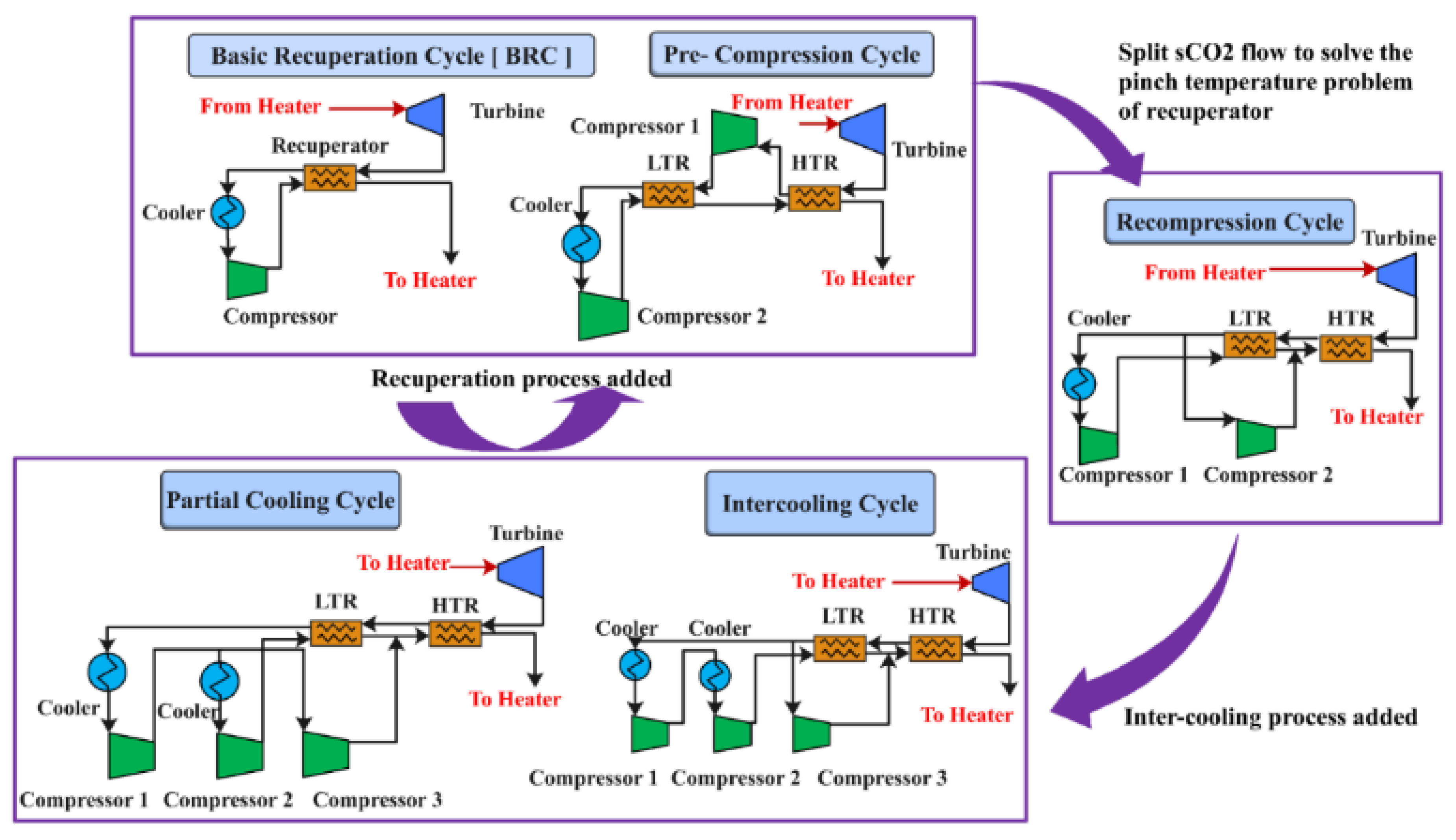
Figure 4.
Schematics and T-S diagrams of: (a) SRC; (b) RCBC reheated (c) RCBC; (d) TCC [24].
Figure 4.
Schematics and T-S diagrams of: (a) SRC; (b) RCBC reheated (c) RCBC; (d) TCC [24].
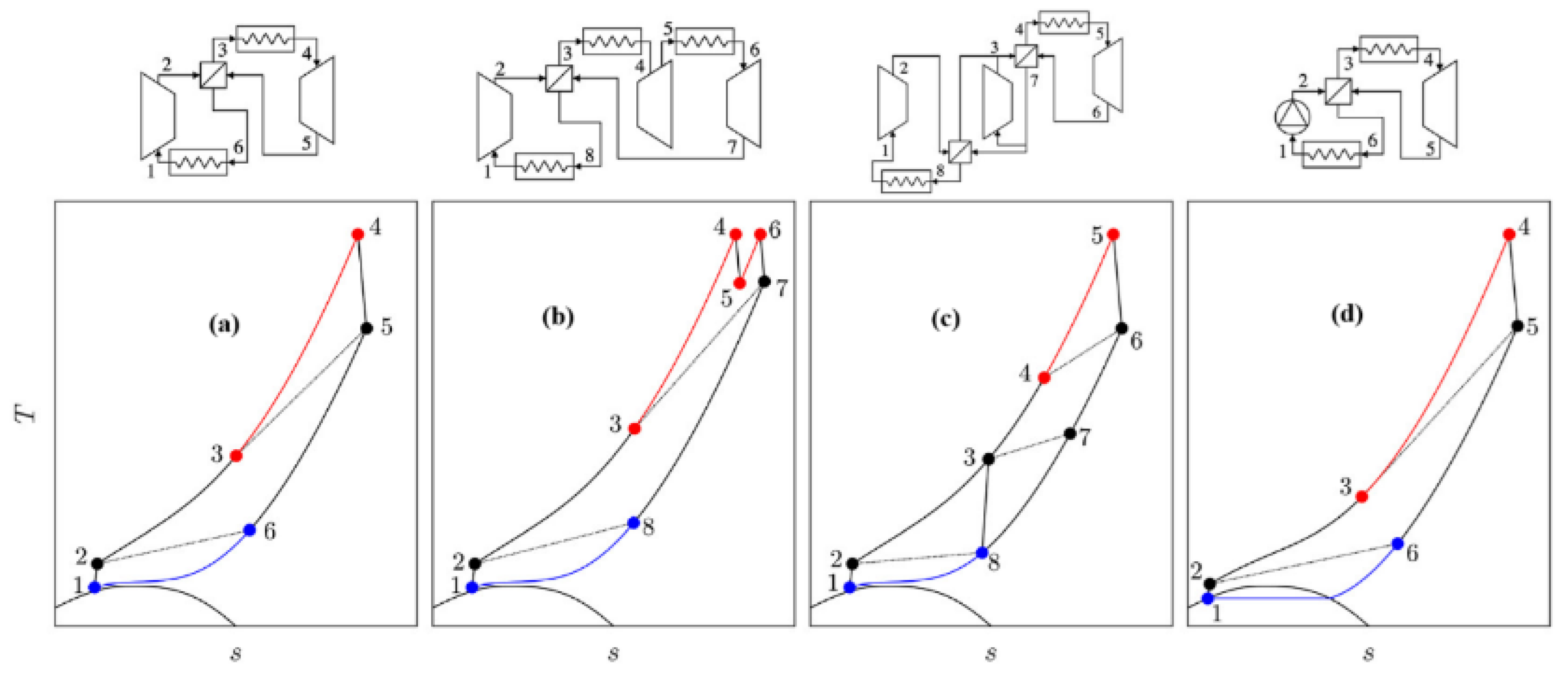
Figure 5.
SANDIA labs research progress since 2007 [34].
Figure 5.
SANDIA labs research progress since 2007 [34].
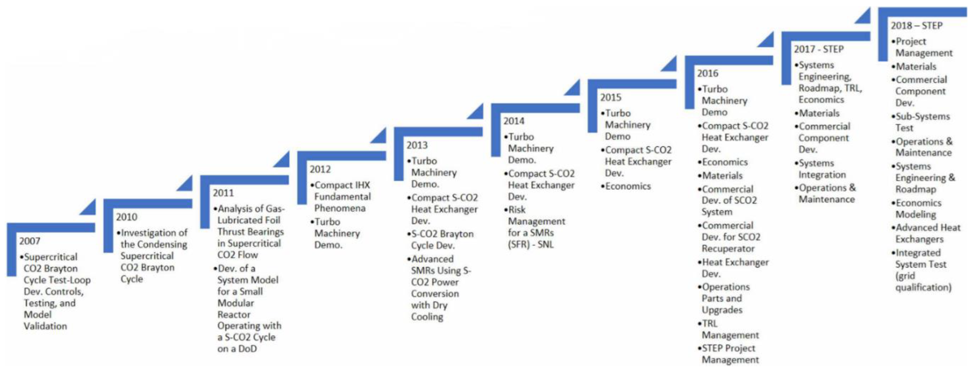
Figure 7.
Project Sunshot’s CSP LCOE 2030 goal [52].
Figure 7.
Project Sunshot’s CSP LCOE 2030 goal [52].
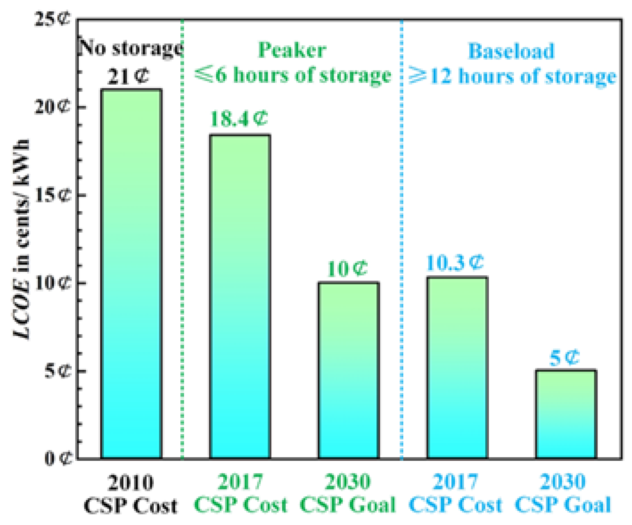
Figure 8.
Example of (a) a Diamond TPMS molten salt-sCO2 heat exchanger exchanger [77], (b) Gyroid heat exchanger [89] and an illustration of a functionally graded HX [77].
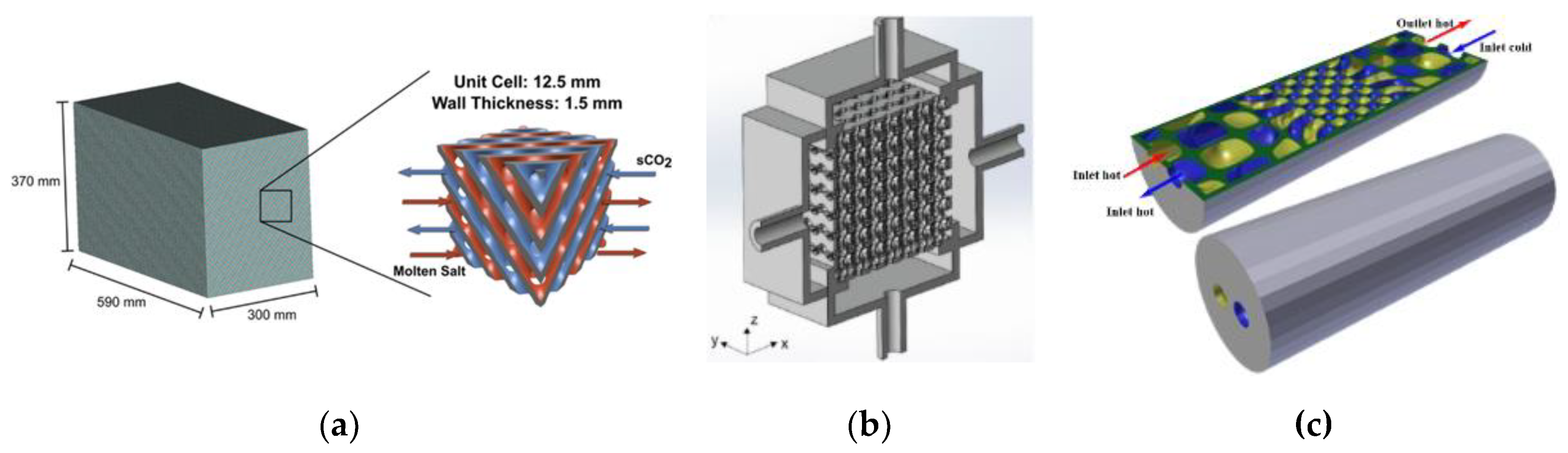
Figure 9.
Reynolds number against (a) Nu. and (b) f in laminar regime [91].
Figure 9.
Reynolds number against (a) Nu. and (b) f in laminar regime [91].
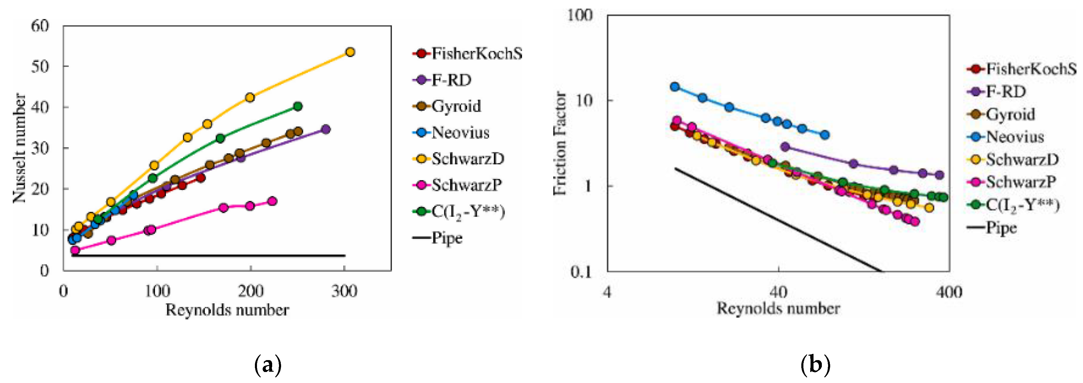
Figure 10.
Reynolds number against (a) Nu. and (b) f in 0 > Re > 500 [92]
Figure 10.
Reynolds number against (a) Nu. and (b) f in 0 > Re > 500 [92]
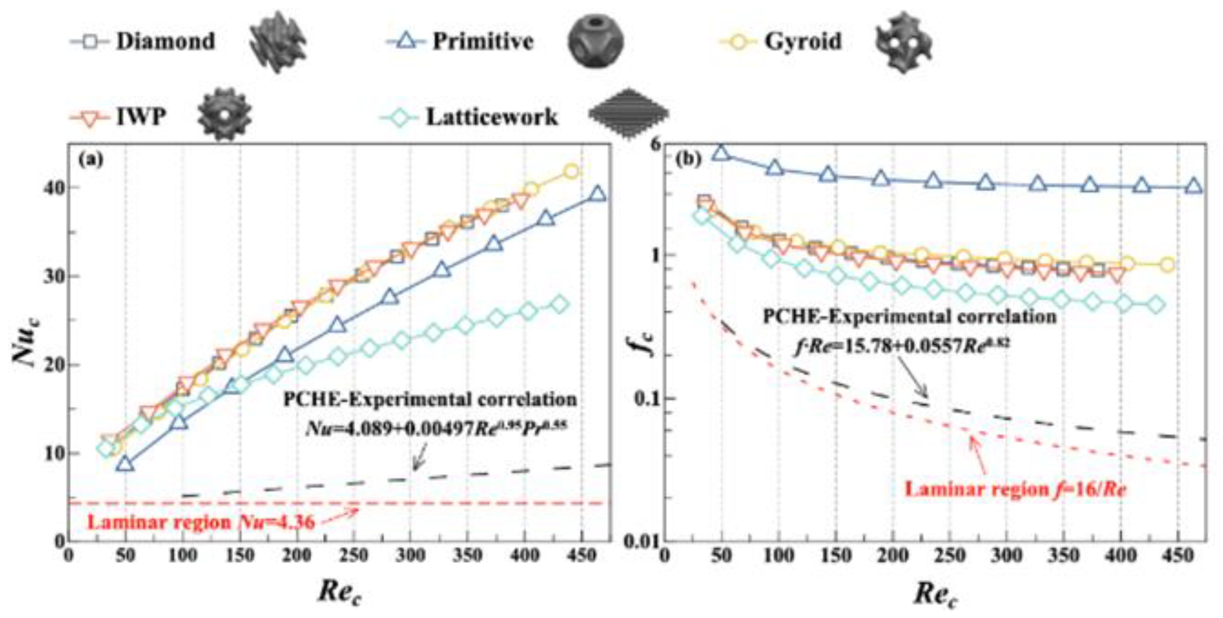
Figure 11.
Performance evaluation coefficient
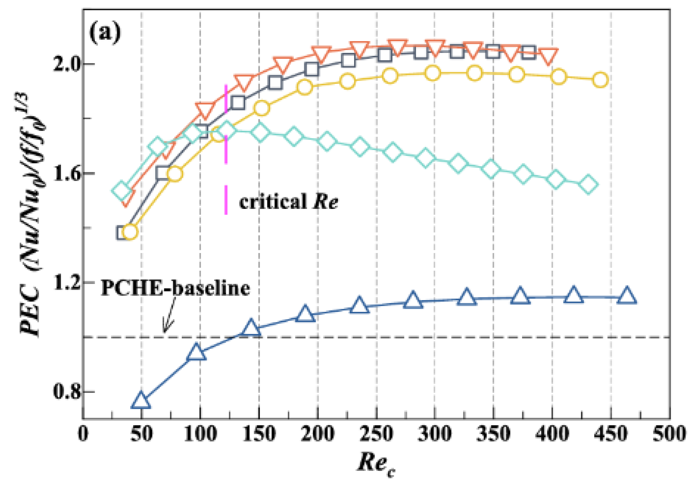

Table 1.
Thermophysical properties of CO2 against other common working fluids.
| Fluid | CO2 | H2O | He | Air |
|---|---|---|---|---|
| Molecular weight | 44.01 | 18.015 | 4.0026 | 28.965 |
| Critical density/kg.m3 | 467.6 | 322 | 72.567 | 342.68 |
| Critical temperature/K | 304.13 | 647.1 | 5.1953 | 132.53 |
| Critical pressure/MPa | 7.3773 | 22.064 | 0.2276 | 3.786 |
| Project | Features |
|---|---|
| EPS100 (USA) | 8 MW, 532 oC, 24 % efficiency |
| NET Power, 8 Rivers Capital (USA) | Combustion gas, zero emission, 100% CO2 capture, high efficiency, low cost |
| STEP (USA) | 10 MW, 169 mil. US$ cost |
| SOLARSCO20L (EU) | 2 MW, Based on CSP, molten salt |
| Xi’an Thermal Power Co. Ltd., Harbin Boiler Co. Ltd. (China) | 5 MW, 33 MPa |
| Dunhuang, Shouhang IHW (China) | Solar thermal power plant, 10 MWe |
| Hengshui Zhongke HENGFA power Equipment Co. Ltd. (China) | 40 MPa PCHE pressure |
Table 3.
Energy and exergy efficiencies of RCBC.
| Power plant | Energy eff. (%) | Exergy eff. (%) | Author/s |
|---|---|---|---|
| RCBC, TCC | 46.43 | 80.59 | [55] |
| RCBC | 43.22 | 75.01 | [55] |
| RCBC with MC intercooling & reheating | 42.7 - 52.2 | 22.3 – 22.9 | [26] |
| RCBC with MC intercooling | 41.3 – 53.8 | 21.6 – 22.4 | |
| RCBC with partial cooling & reheating | 41.1 - 54 | 21.5 – 22.4 | |
| RCBC with partial cooling | 39.2 – 52.3 | 20.5 – 21.7 | |
| RCBC | 40.1 – 51.8 | 20.5 – 21.5 | |
| RCBC with reheating | 41.1 – 52.8 | 20.9 - 22 | |
| RCBC | 33.8 | - | [56] |
| RCBC | 47.43 | - | [57] |
| RCBC tri-compression | 49.47 | - | [57] |
| RCBC dry cooled | 50.9 | - | [58] |
| RCBC | 23.6 | - | [59] |
| RCBC with partial cooling | 24.4 | - | |
| RCBC with intercooling | 24.5 | - | |
| RCBC with ORC bottoming | 63.86 – 85.83 | 35.57 – 47.82 | [60] |
| > 50 | - | [61] |
Table 4.
Energy, exergy and cost optimization studies of RCBC.
| Power plant | Optimization scheme | Energy eff. Function (%) | Electricity cost function | Author/s |
|---|---|---|---|---|
| RCBC | - | - | 0.0826 $/kWh | [62] |
| RCBC, intercooling & preheating | - | 35.6 | [63] | |
| RCBC | - | 46 | 0.11 $/kWh | [64] |
| RCBC | - | 48.8 | 0.0598 $/kw | [65] |
| RCBC partially cooled | - | 55 | (5015)a | [66] |
| RCBC | - | 36.6 | 0.059 $/kWh | [67] |
| RCBC | GA, NSGA-II | 26.3 – 29.8 | ||
| RCBC with partial cooling | 27.2 – 29.6 | [68] | ||
| RCBC with intercooling | 28.3 – 31.2 | |||
| RCBC | 29.4 – 31.3 | [69] | ||
| RCBC with partial cooling | GA | 28.3 – 30 | ||
| RCBC with intercooling | 29.6 – 31.5 | |||
| RCBC | 15.30 c/kWh | [70] | ||
| RCBC | 3930 $/kW | [154] |
aOvernight capital costs,$/kW.
Table 5.
Energy, exergy and optimization equations for the RCBC and TCC.
| Equipment | Energy | Exergy | |
|---|---|---|---|
| RCBC | Turbine 1 | ||
| HTR | |||
| LTR | |||
| MC | |||
| Precooler-2 | |||
| RC | |||
| Heater | |||
| Efficiency | |||
| Power | |||
| TCC | Turbine 2 | ||
| Precooler-1 | |||
| Power | |||
| Optimization | …(1) where …(2), …(3), …(4), …(5)…(6) | ||
| …(7) …(8) …(9) …(10) | |||
| …(11) …(12)…(13) | |||
Table 6.
The parameters of PCHE in academic and research institutions.
| Institution | Fluids | Channel | Material |
iDh /mm |
HTAj /m2 |
Refs. | Parameters Temp./oC, Pressure/MPa, **m/kgh-1 |
|---|---|---|---|---|---|---|---|
| KAIST | CO2 | Z | SS316L | 1.8 | [96] |
S channel; Tcold: 23.1-108, Thot:25.4-300, Phot: 2.2-11.97, Pcold: 0.14-18, m: 20-650 Z channel; Tcold: 8-580, Thot:8-580, Phot: 1.0-9.5, Pcold: 0.1-22.5, m: 10-3636 Teardrop fin; Thot: 70–110, Phot: 7.6–9.0, mhot: 500–1800, Tcold: 16–25, Pcold: 0.1, mcold: 3m3h1 |
|
| He/CO2 | Z | Alloy 800HT | 0.922/0922 | 3.8/3.8 | [90,97] | ||
| CO2/H2O | Z | SS316L | 1.167 | 0.8 | [98] | ||
| TIT | CO2 | Z/SS | kSS316L | 1.09/1.09 | S:0.5099/0.2559 Z: 0.4653/0.2353 |
[99] | |
| CO2 | Z | 1.9/1.8 | 0.697/0.356 | [100] | |||
| CO2 | Z/SS | 1.88 | [101] | ||||
| GITa | CO2 | Rectangular NACA 0020 Airfoil |
SS316L | 0.9973 1.112 |
91.133* 24.94* |
[102] | |
| USTCb | CO2 | SS | mole steel M280 | [103] | |||
| CO2 | SS | steel M280 | 1.12/0.95 | 0.095821/0.101306 | [104] | ||
| SUc | CO2/H2O | S | SS316L | 1.14 | [105,106] | ||
| CASd | CO2 | Z | SS316L | [107] | |||
| CO2 | Z | SS316L | 1.83 | 2.291 | [108] | ||
| CO2/H2O | Z | SS316L | 1.5/1.6 | [109] | |||
| CO2/H2O | Teardrop fin | [110] | |||||
| XJUe | CO2/H2O | S | SUS304 | [111] | |||
| CO2/H2O | Z | SUS304 | 2.0 | [112] | |||
| WSMEf | He/CO2 | Z | SS316L | 1.0 | 0.14 | [113] | |
| ZUg | CO2 | - | 193 | ||||
| USh | CO2/H2O | Z | X5CrNi18-10 | 1.33 | [114] |
aGeorgia Institute of Technology, bUniversity of Science and Technology of China, cSoutheast University, dChine Academy of Sciences, eXi’an Jiaotong University, fWoodruff School of Mechanical Engineering, gZhejiang University, hUniversity of Stuttgart, ihydraulic diameter, jheat transfer area, kmicrochannel printed HX, *unite cell HTA, **mass flow rate.
Disclaimer/Publisher’s Note: The statements, opinions and data contained in all publications are solely those of the individual author(s) and contributor(s) and not of MDPI and/or the editor(s). MDPI and/or the editor(s) disclaim responsibility for any injury to people or property resulting from any ideas, methods, instructions or products referred to in the content. |
© 2024 by the authors. Licensee MDPI, Basel, Switzerland. This article is an open access article distributed under the terms and conditions of the Creative Commons Attribution (CC BY) license (http://creativecommons.org/licenses/by/4.0/).
Copyright: This open access article is published under a Creative Commons CC BY 4.0 license, which permit the free download, distribution, and reuse, provided that the author and preprint are cited in any reuse.


