Submitted:
21 December 2024
Posted:
26 December 2024
You are already at the latest version
Abstract
This study proposes a novel Inverse Rotating Drive Shaft System (IRDSS) to mitigate torque twist and enhance climbing stability in Radio-Controlled (RC) crawlers. By counteracting torque-induced rollovers through reverse angular momentum, the IRDSS aims to improve performance on uneven terrains. The study combines real-world testing on simulated terrains, dynamic simulations using RecurDyn, and theoretical analyses to evaluate two RC crawler models: one with the IRDSS and one with a standard transmission. Results showed that the IRDSS-equipped crawler achieved a 7.5% improvement in maximum climb angle on high-friction surfaces, reaching 64.8° compared to 60.3° for the standard model. However, on low-friction surfaces, both models were traction-limited, achieving similar climb angles of approximately 48°. These findings highlight the IRDSS's ability to enhance performance in high-friction environments, offering insights into optimizing RC crawler designs for stability and climbing capability under varied terrain conditions.
Keywords:
Inverse Rotating Drive Shaft System (IRDSS)
; RC Crawlers
; Climbing Performance
; Torque Twist Mitigation
; Terrain Friction Analysis
; Mechanical Engineering
; Vehicle Dynamics
; Simulation (RecurDyn)
Introduction
Radio-Control (RC) Crawlers are usually built in small scale to simulate real vehicles for entertainment, they can be designed to navigate steep and uneven terrains, which requires precise engineering to optimize their stability and maneuverability. [1] The mechanical design of (RC) four-wheel drive crawlers significantly influences their dynamic performance. Since the introduction of the first RC crawler kit in 2007, these vehicles have become highly popular and the best selling type in the RC market, appealing due to their accessibility and minimal experience requirements for users. Compared to 5.1k followers for RC buggy group in Facebook, there are over 26 thousand accounts in the Facebook Group “RC Crawlers”, which can prove how welcoming this specific type of RC crawler is. [2,3] The design of RC crawlers must account for how each component affects the vehicle’s overall performance. [4]
The introduction of an Inverse Rotating Drive Shaft System (IRDSS) presents a novel approach to enhancing these capabilities for climbing and crossing the uneven terrains. By counteracting the torque produced by the main drive shaft with an opposite rotation, this system aims to reduce the net angular momentum. This would potentially increase stability and reduce the tendency for roll-overs, which is critical in uneven terrains.
Furthermore, the mass distribution within an RC vehicle is crucial for maintaining traction and balance. Adjustments to the vehicle’s mass, whether through redistribution or total mass alteration, can significantly affect its ability to climb steep inclines. [5] An optimally distributed mass not only supports greater slope ascent but also contributes to a lower center of gravity, reducing the risk of roll-overs.
The process involves simulating the different friction of different terrain and the weight on the crawler, which uses different kinds of transmission, as well as making sure the data collection is correct.
This paper examines the effects of incorporating an IRDSS and the mass distribution on the climbing capabilities of RC crawlers. By introducing IRDSS, the RC crawler could have a larger maximum angle climb and reduce the torque twist that might cause a body roll and reduce the friction force. It focuses on critical performance indicators, including the maximum slope angle achievable and the risk of roll-overs under varying terrain conditions.
2. Materials And Methods
2.1. Material Needed
2.1.1. Crawler Build
Table 1 shows the parts bought from the RC factory in China, including two transmissions that have the same structure of the AX10 transmission.
2.1.2. Test Incline Build
The testing board is composed of a wooden board and two sets of sandpaper tracks as shown in Figure 1, used to simulate the different grips under the different surfaces of the run condition.
2.2. Real World Setup
Sandpaper with different grips is used to simulate the run conditions under the different surfaces — the coastal rock surface, dry clay surface and the perfect grit condition — and to control the bias.
Sandpaper with grit number 40-60 is used to simulate the clean coastal rock with a coefficient of efficiency around 0.85. Sandpaper with grit number 150-220 is used to simulate the clay surface on the clay hill with a coefficient of efficient around 0.4
2.3. Chassis Passability Theory Analysis
2.3.1. Ideally Climbing Angle Analysis
When the crawler is crawling upward, the force exerted on the crawler includes gravity, the normal force of the ground, and the friction between the tire and the surface.
The downward torque exerted by gravity refers to the torque generated by the component of gravitational force that is perpendicular to the line connecting the center of mass and the rear output axle and acts downward. This torque tends to rotate the crawler in a way that keeps it stable, preventing it from tipping over.
The upward torque exerted by gravity refers to the torque generated by the component of gravitational force that is perpendicular to the line connecting the center of mass and the rear output axle and acts upward. This torque tends to rotate the crawler in a way that could lead to it tipping over.
Under these conditions, the pressure on the front tire will not be zero. Once the pressure on the front wheel equals to zero, the crawler will roll over.
General Chassis Free Body Diagram
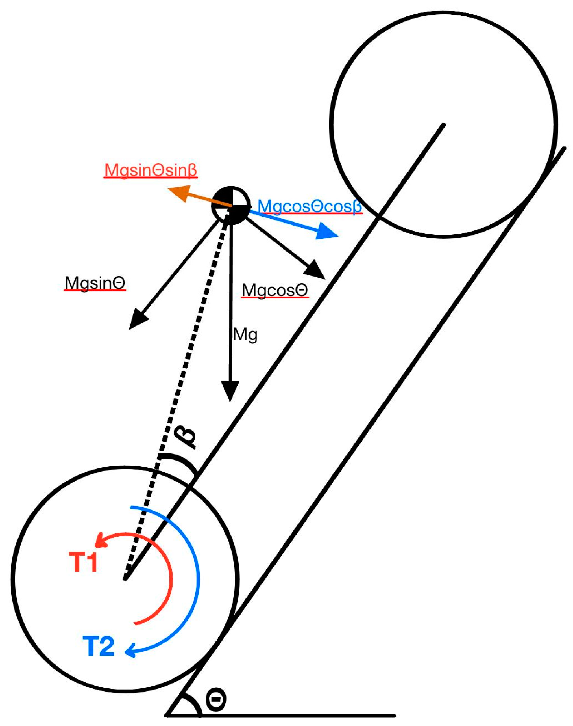
Diagram 1: Free body diagram of RC crawler
M is the mass of the crawler, g is the gravitational acceleration, and θ is the slope angle. The gravitational force could be represented by the component
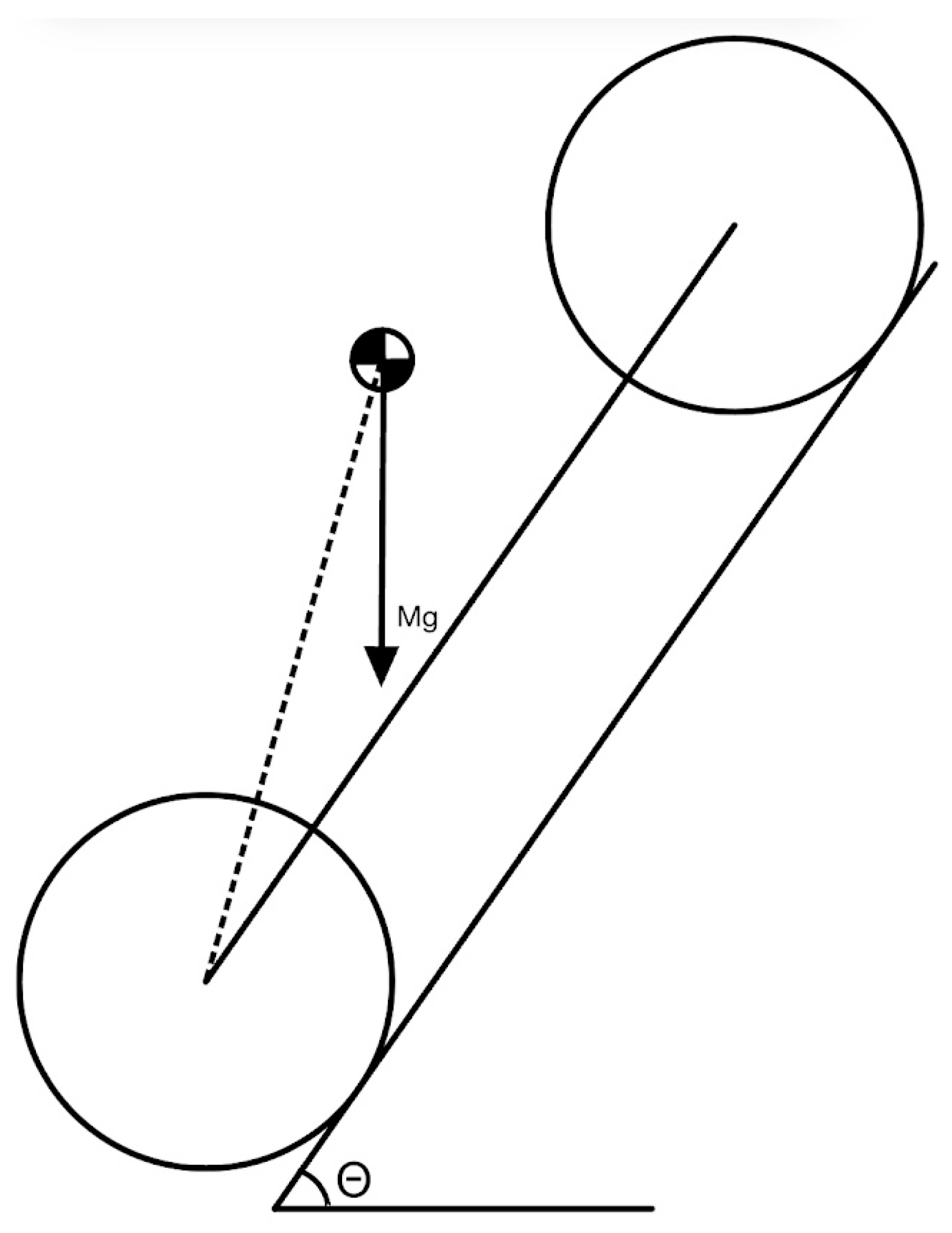
Diagram 2: The gravity force act on crawler
The line connected to the front and rear axle is perpendicular to the slope surface
The resolution of force Mg will be
parallel to the slope (the connecting line of front and rear axle):
perpendicular to the slope(the connecting line of front and rear axle):
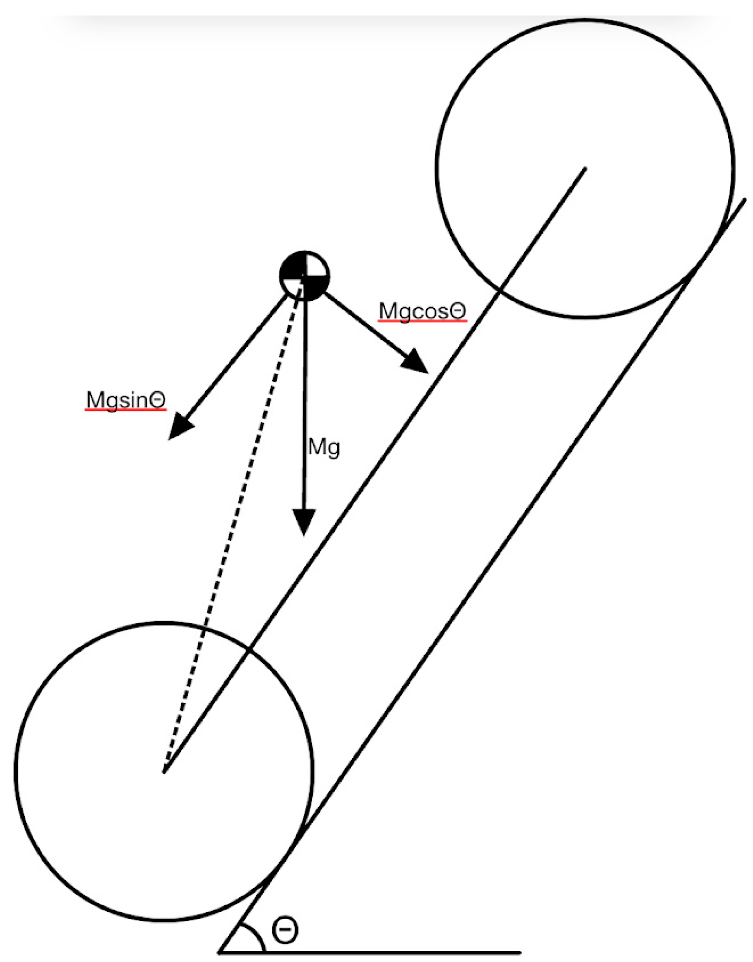
Diagram 3: The resolution of the force Mg
ꞵ is the angle between and the connection line between the center of mass and the slope, and L is the length of the connection line between the rear output axle and the center of mass (shows in dot line). The torque exerted on the axle by the gravitational force on counterclockwise can be represented by (Diagram 4) and clockwise by (Diagram 5).
backward(CCW):
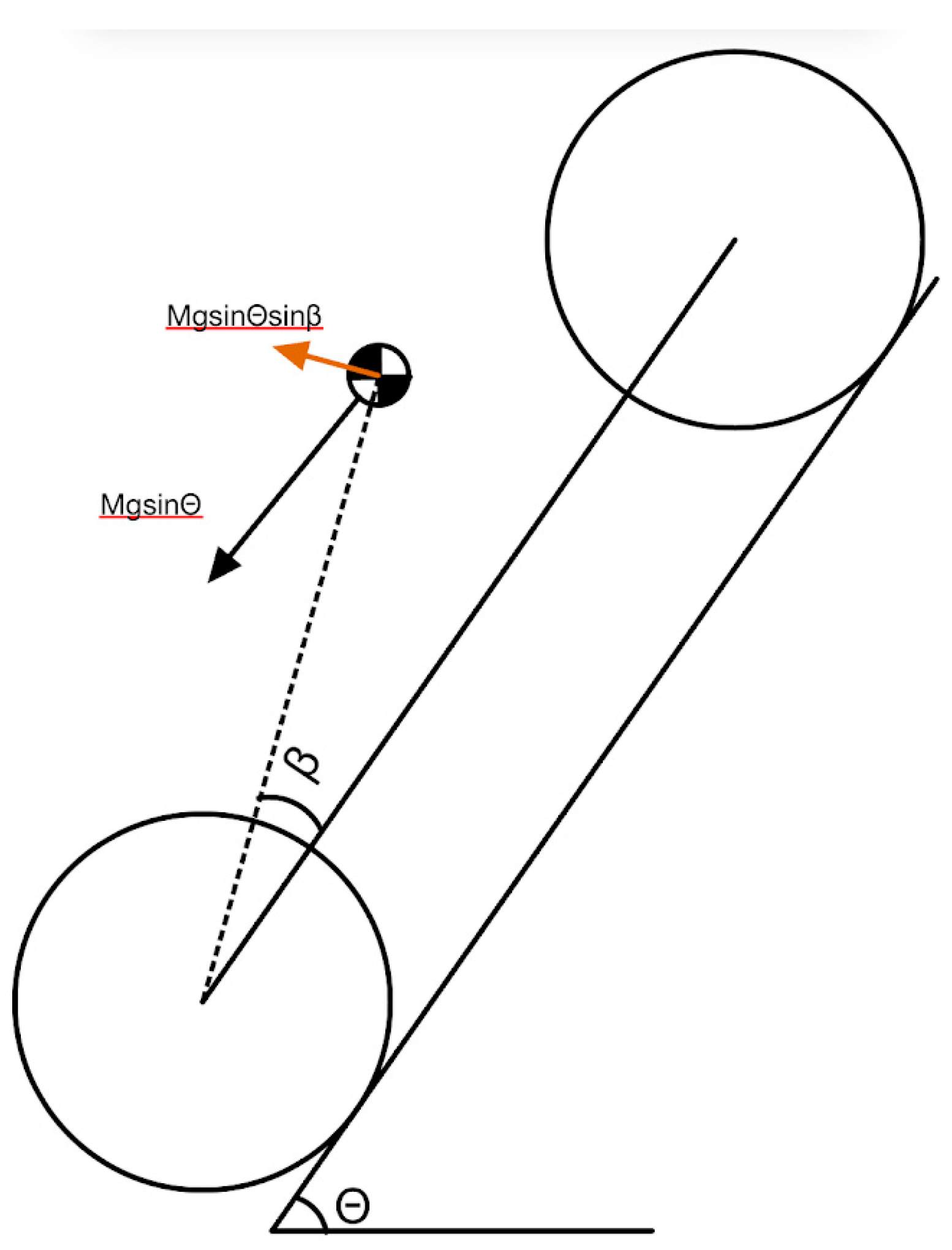
Diagram 4: The resolution of force Mg sin, the force perpendicular to the line L
downward(CW):
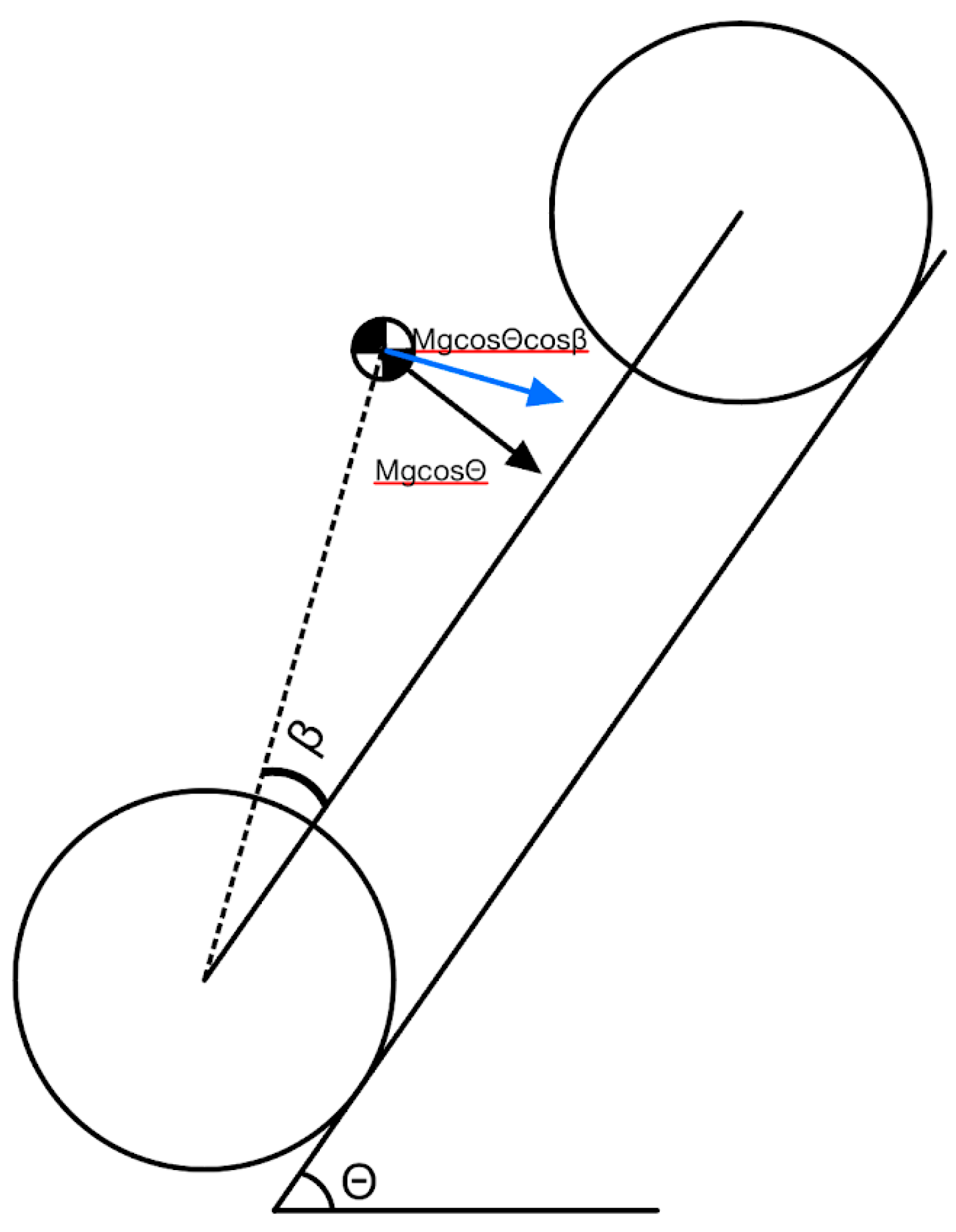
Diagram 5: The resolution of force Mg cos, the force parallel
When the clockwise and counterclockwise torques reach equilibrium, the crawler will reach its maximum theoretical climbing angle as shown in Diagram 6.
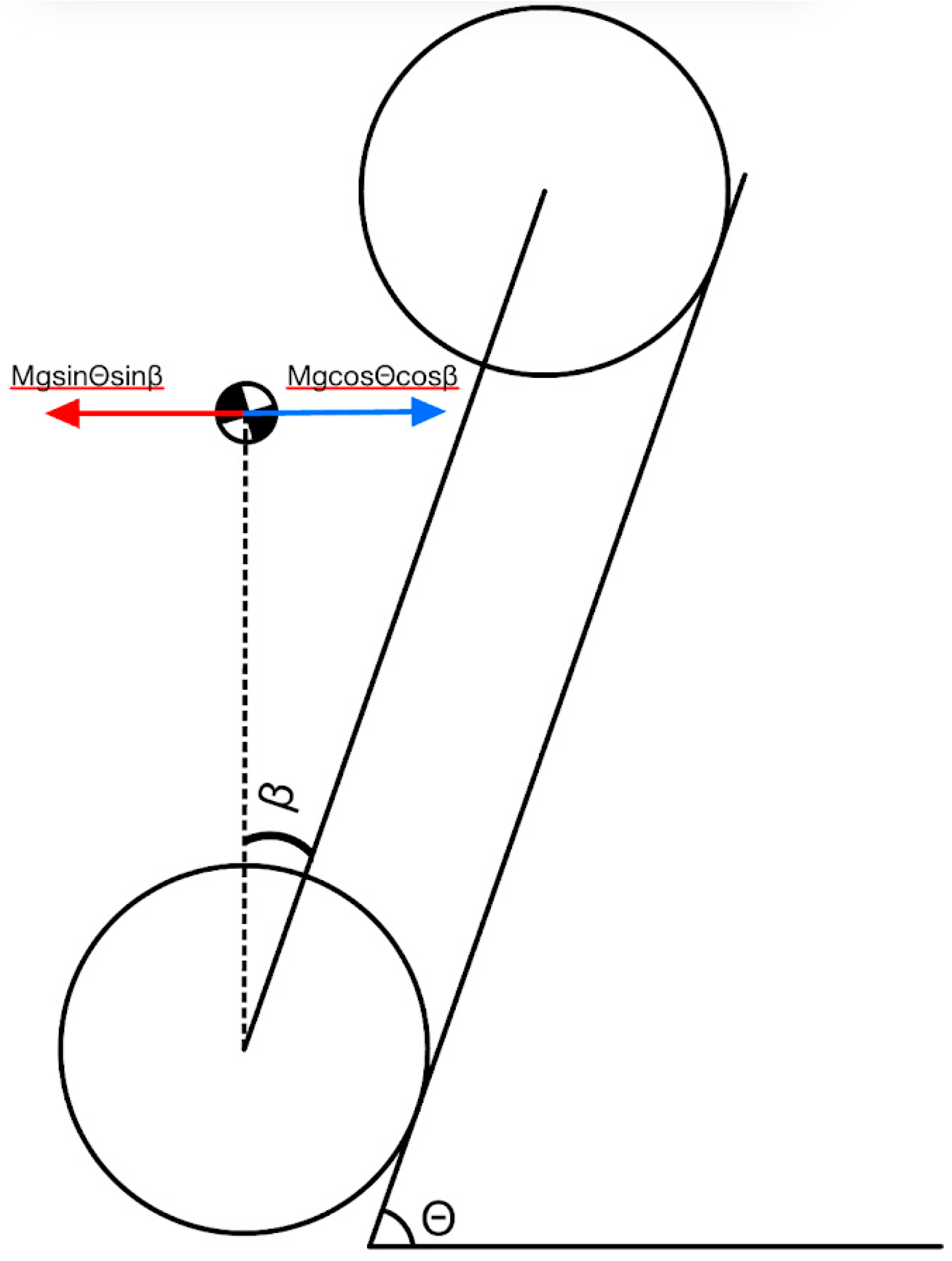
Diagram 6: The theoretical maximum climbing angle analysis. The figure shows the balancing of the two torques achieved when the crawler reaches its maximum theoretical climbing angle.
Simplify:
The line labeled H represents a perpendicular line from the center of mass to the line connecting the front axle and the rear axle.
2.3.2. Torque Analysis
Torque twist occurs in RC crawlers when torque generated by the motor and transmitted through the drivetrain interacts with the suspension system. This phenomenon arises due to the reactionary force generated by the torque acting on the axle housing. Without appropriate countermeasures, this reaction can destabilize the vehicle by causing the chassis to twist, thereby reducing traction and climbing efficiency.
When the motor applies torque to the drivetrain, the axles experience a reactive rotational force opposing the direction of torque. This reactive force acts on the suspension linkage, compressing one side and extending the other. The magnitude of this reaction can be expressed mathematically. The torque applied at the axle, Ta, is calculated as:
where Tm represents the motor torque and Rg is the gear ratio. The reactive force on the suspension linkage, FrF_rFr, is derived from:
Where La is the moment arm, or the distance from the axle to the suspension mount point. This force causes displacement in the suspension, which can be expressed as:
Ts = Tm × Rg
Fr = La / Ta
Ds = ks / Fr
Here, ks is the suspension spring constant. In a standard RC crawler, the reactive force leads to uneven weight distribution and suspension behavior. This creates instability, particularly when climbing steep inclines, as the twisting motion shifts the weight and reduces the effective traction.
The introduction of the Inverse Rotating Drive Shaft System (IRDSS) addresses this issue by counteracting the torque-induced twist. The IRDSS generates an opposing angular momentum through reverse rotation of the drive shaft, effectively reducing the net reactive force acting on the suspension. This system mitigates the compression and extension of the suspension components, maintaining an even weight distribution across all wheels.
2.4. Computational Analysis Using RecurDyn
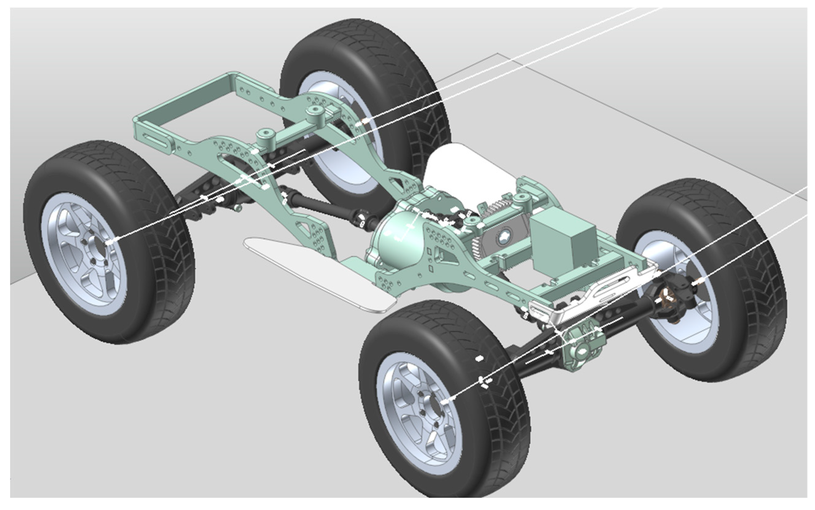
To enhance the understanding of the RC crawler’s performance, a computational analysis was conducted using RecurDyn, a multi-body dynamics simulation software. This approach facilitated the evaluation of the crawler’s dynamic behavior, focusing on torque twist mitigation, climbing stability, and the effects of incorporating the Inverse Rotating Drive Shaft System (IRDSS). RecurDyn provided a platform for predicting performance under controlled, simulated conditions, bridging theoretical analysis and real-world testing.
The simulation model was constructed to reflect the physical properties and configurations of the RC crawler. The chassis was modeled with a wheelbase of 320 mm. The center of mass was positioned at 45% of the wheelbase from the front axle, consistent with measurements from the physical prototype. Material properties, including the total weight of 2.3 kg, were integrated into the mode. The simulation also replicated real-world boundary conditions by incrementally increasing the slope angle up to 90° and incorporating suspension characteristics.
Figure 2.
RecurDyn general setup.
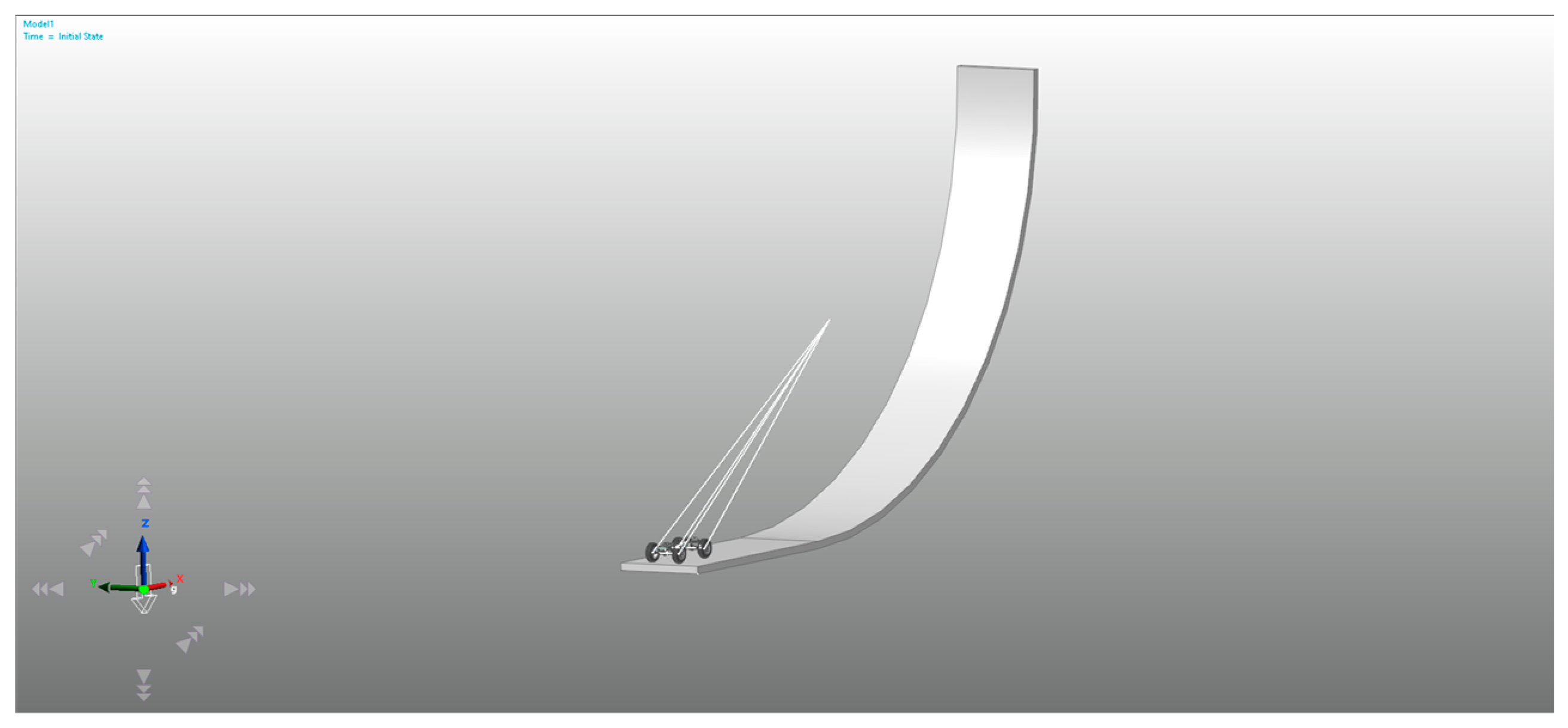
Figure 3.
RecurDyn general setup (sideview).
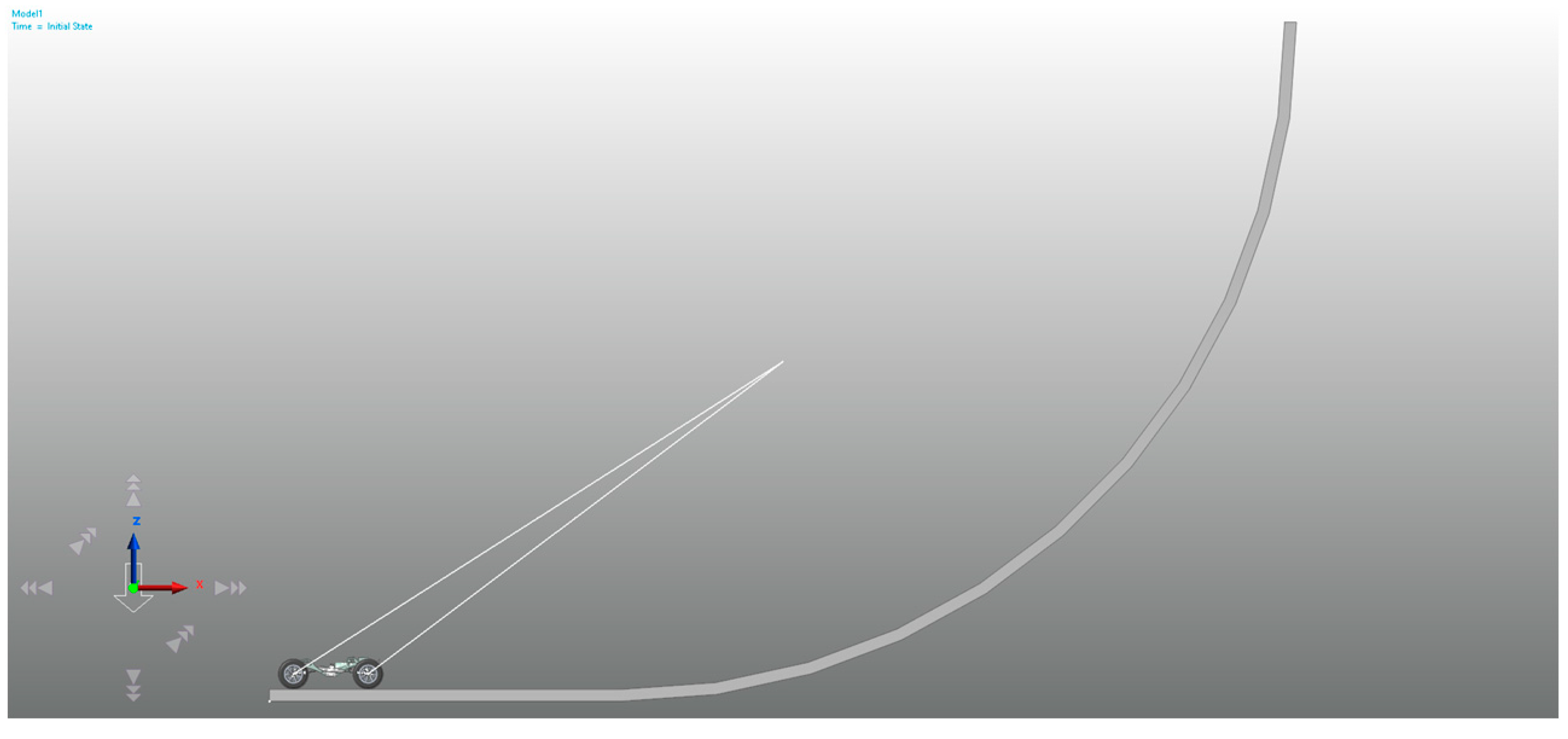
Figure 4.
RecurDyn crawler setup.
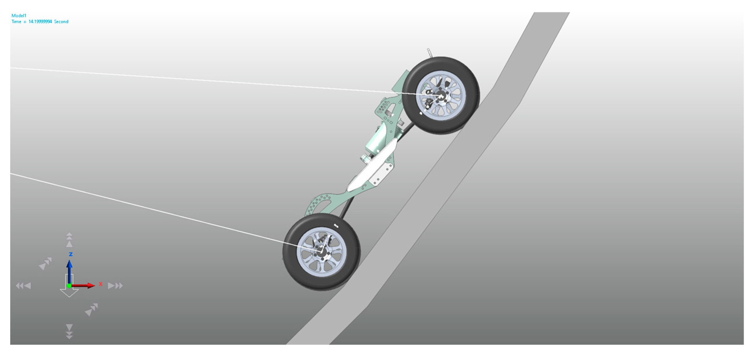
According to the simulation result, the crawler under a clean coastal rock surface will roll over at 56 degrees. And the crawler under the clay surface will begin to slide at 43 degrees.
Figure 5.
The clay surface simulation result, before it starts to sliding.
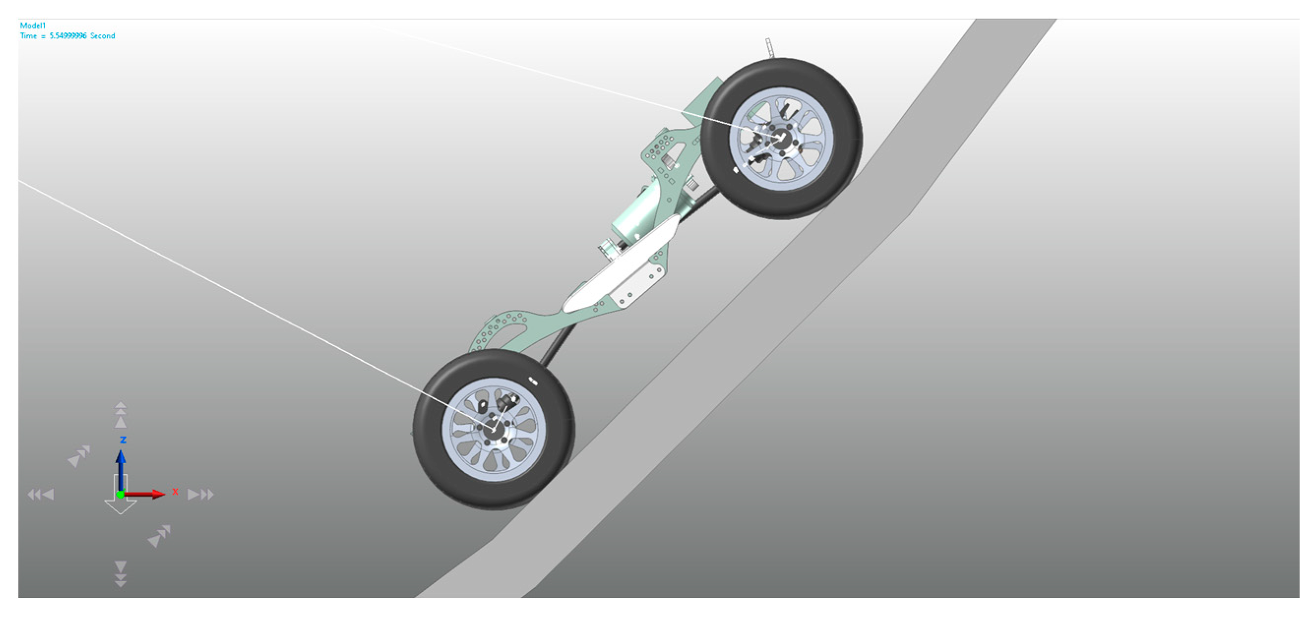
Figure 6.
The costal rock surface simulation result, before it starts to roll over.
2.5. Chassis Build And Data Collection
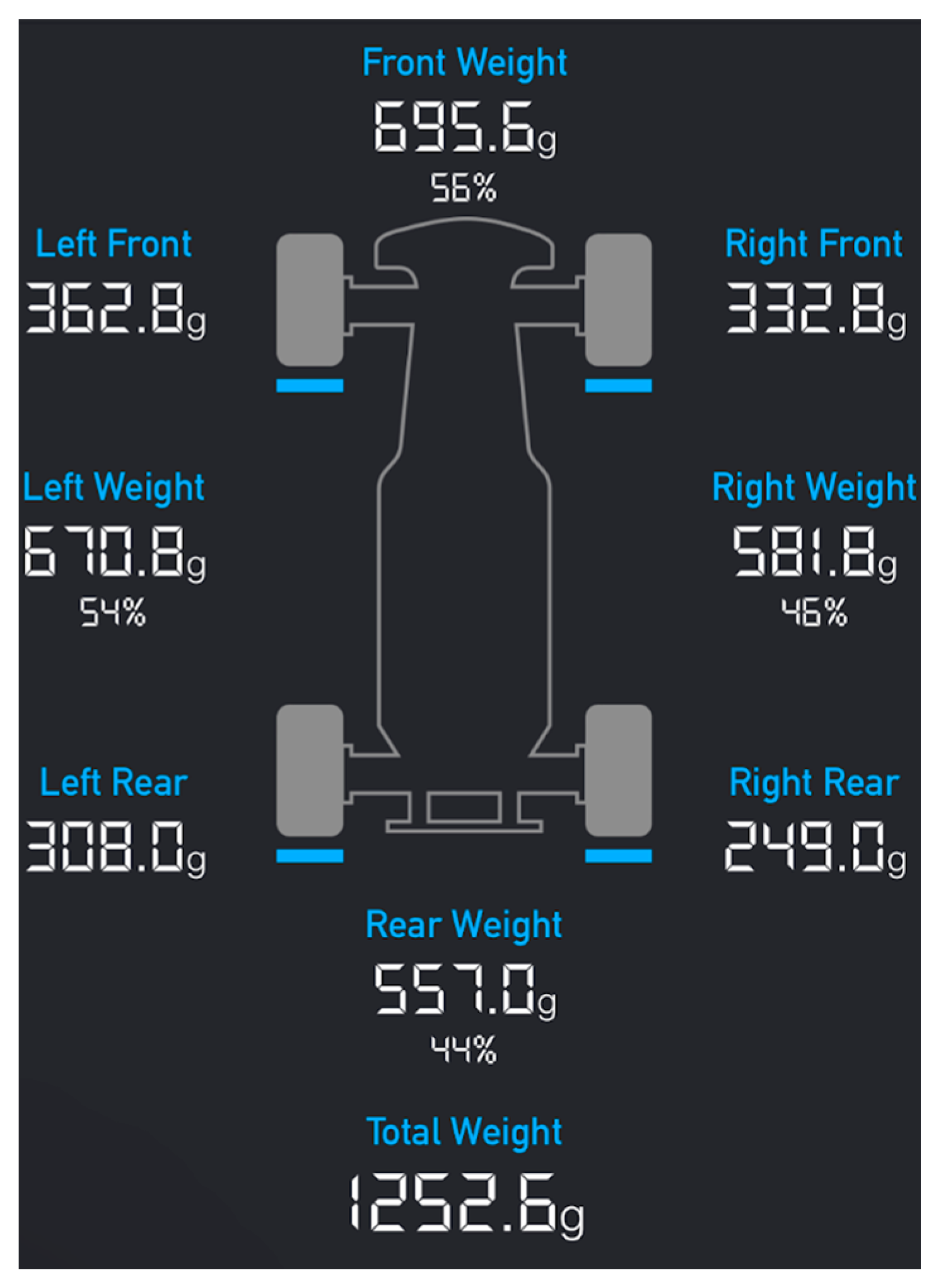
The measurement tools included the SkyRC Corner Weight System to measure the pressure on each tire and to calculate the crawler’s center of mass . After building both the regular crawler and the one with the inverse rotating drive shaft system, the weight and the mass distribution are adjusted by the different battery locations and the extra weight added to the chassis. After adjustments, the left weight and right weight reached a relatively small bias within 1%.
Before adjusting
Figure 7.
Crawler with IRDSS.
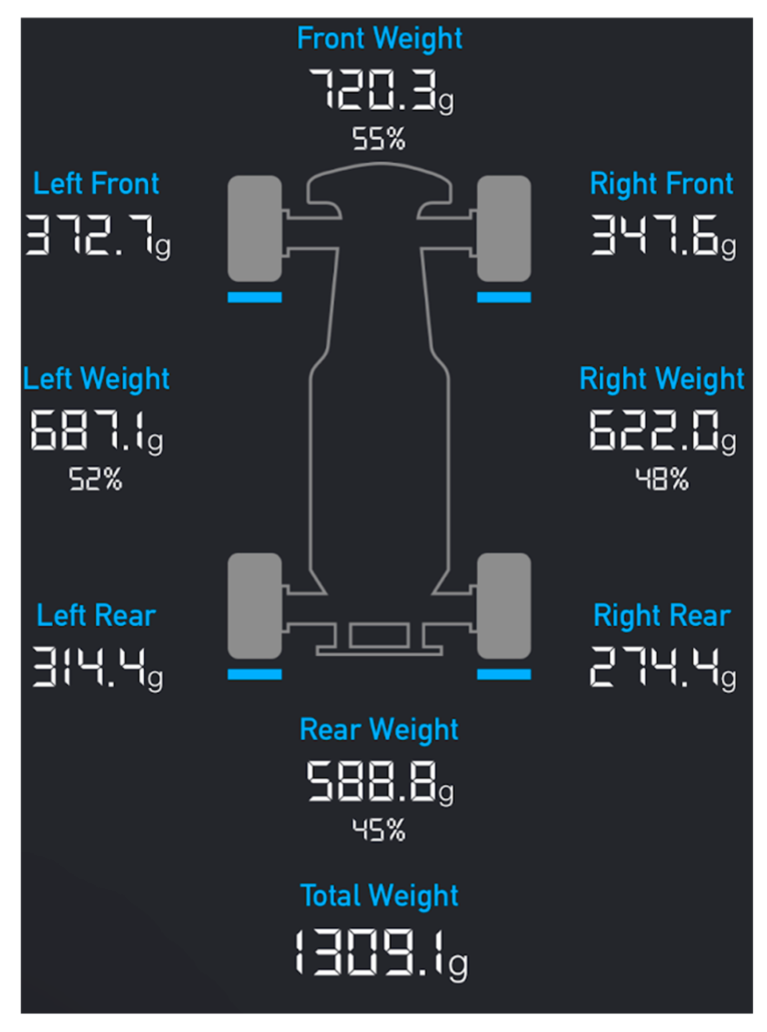
Figure 8.
Crawler with regular transmission.
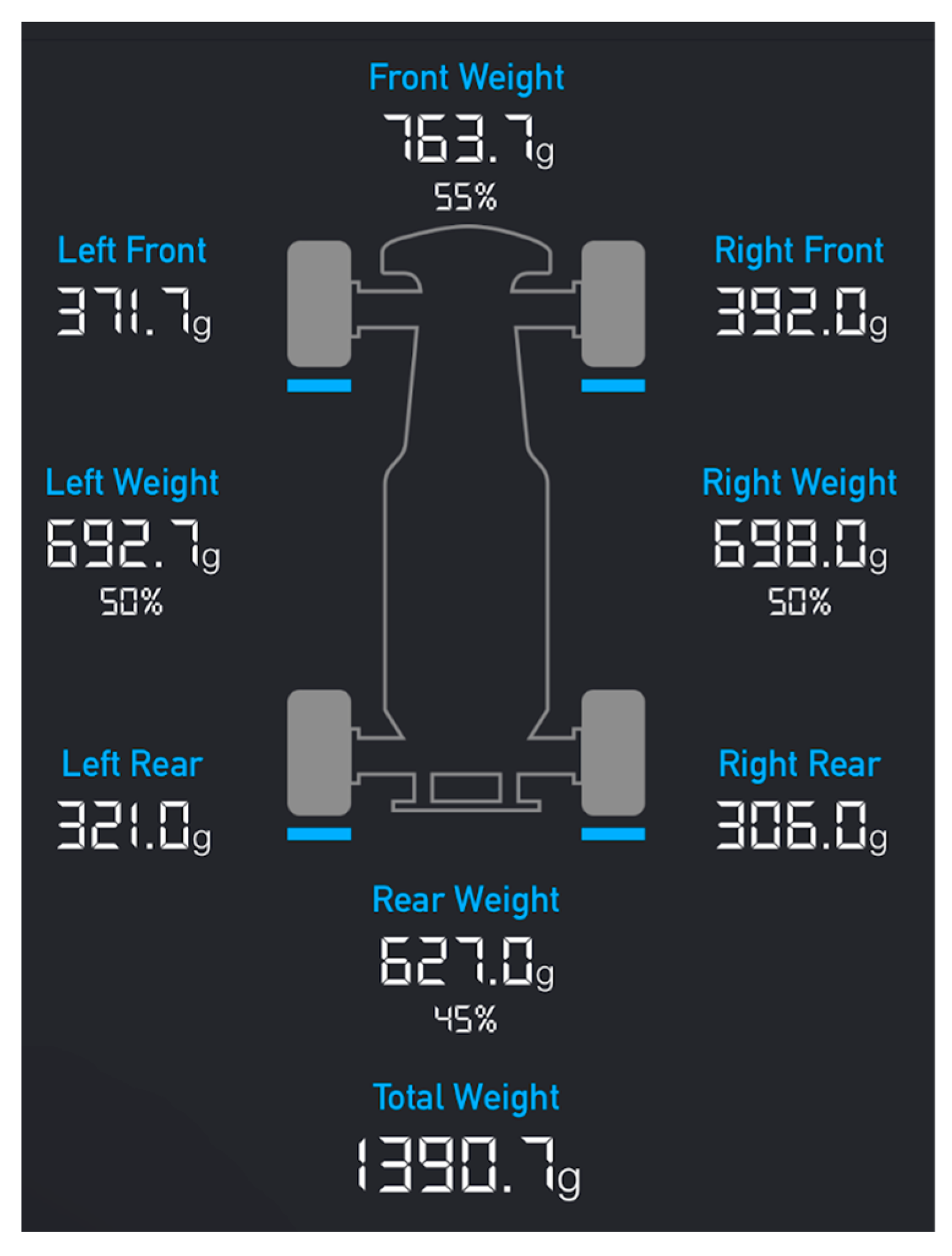
After Adjusting
Figure 9.
Crawler with IRDSS.
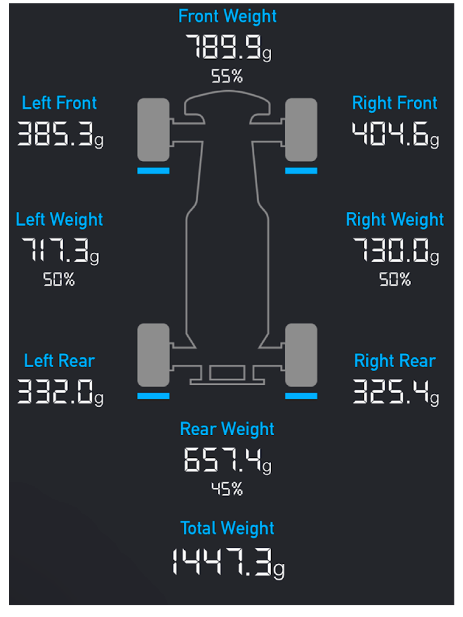
Figure 10.
Crawler with regular transmission.
Center of Mass Measurement And Maximum Climb Angle Analysis
According to the data shown above, the center of mass would be at 55% of the total wheelbase from the rear axle. The wheelbase of both the chassis are 337mm. The center of mass will be located at 185.4mm from the rear axle. After measurement, H equals 66mm, and Equation 1.1 can be used to solve for [6]
3. Real World Testing
To validate the simulation results and theoretical analyses, real-world tests were conducted using both the RC crawler equipped with the inverse rotating drive shaft system (IRDSS) and a standard crawler model. These tests aimed to assess the climbing capabilities, stability, and overall performance of the crawlers on different simulated terrain types. The test was done four times each on the testing board.
3.1. Test On Simulated Coastal Rock Surface
The coastal rock surface was simulated using 40-grit sandpaper, chosen for its rough texture, which closely mimics the grip conditions found on natural rocky terrains near coastlines [7]. The goal was to determine the maximum climb angle achievable by each crawler and observe any instability, such as wheel lift or roll-over, that could occur during the ascent. The final results of the maximum climbing angles for both crawlers are shown in Table 2 as average values.
3.1.1. Standard Crawler Analysis
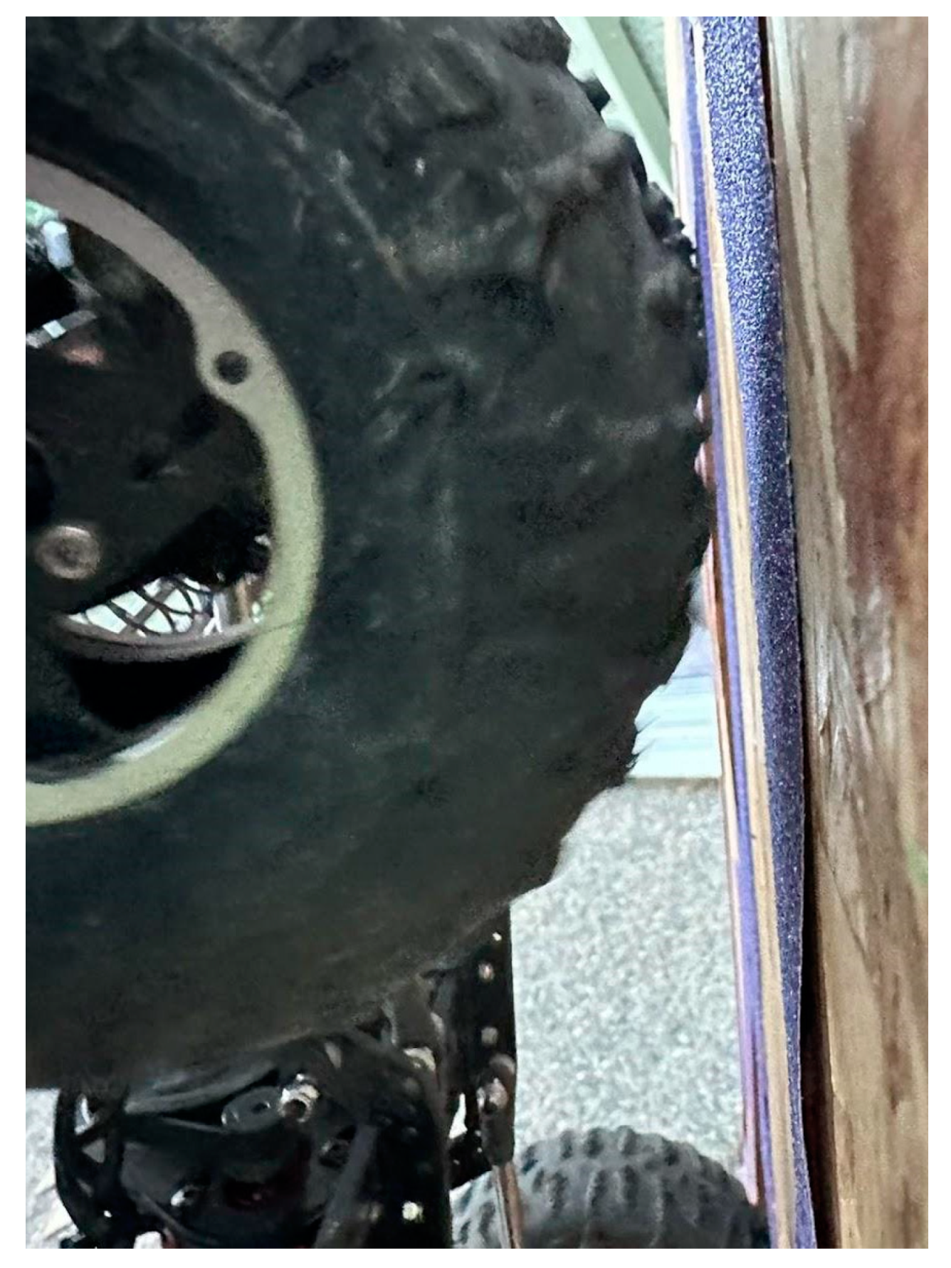
The standard crawler, lacking the IRDSS, exhibited significant instability as the climb angle approached around 60.3°.At approximately 58°, because of the torque twist effect, the right front wheel began to lift off the surface, indicating a loss of balance, and the reduce in friction area, as shown in Figure 8 and Figure 9. As the angle increased to 60.3°, the crawler could no longer maintain its position and rolled over backwards, failing to match the performance of the IRDSS-equipped model.
Figure 11.
inside view of front right wheel.
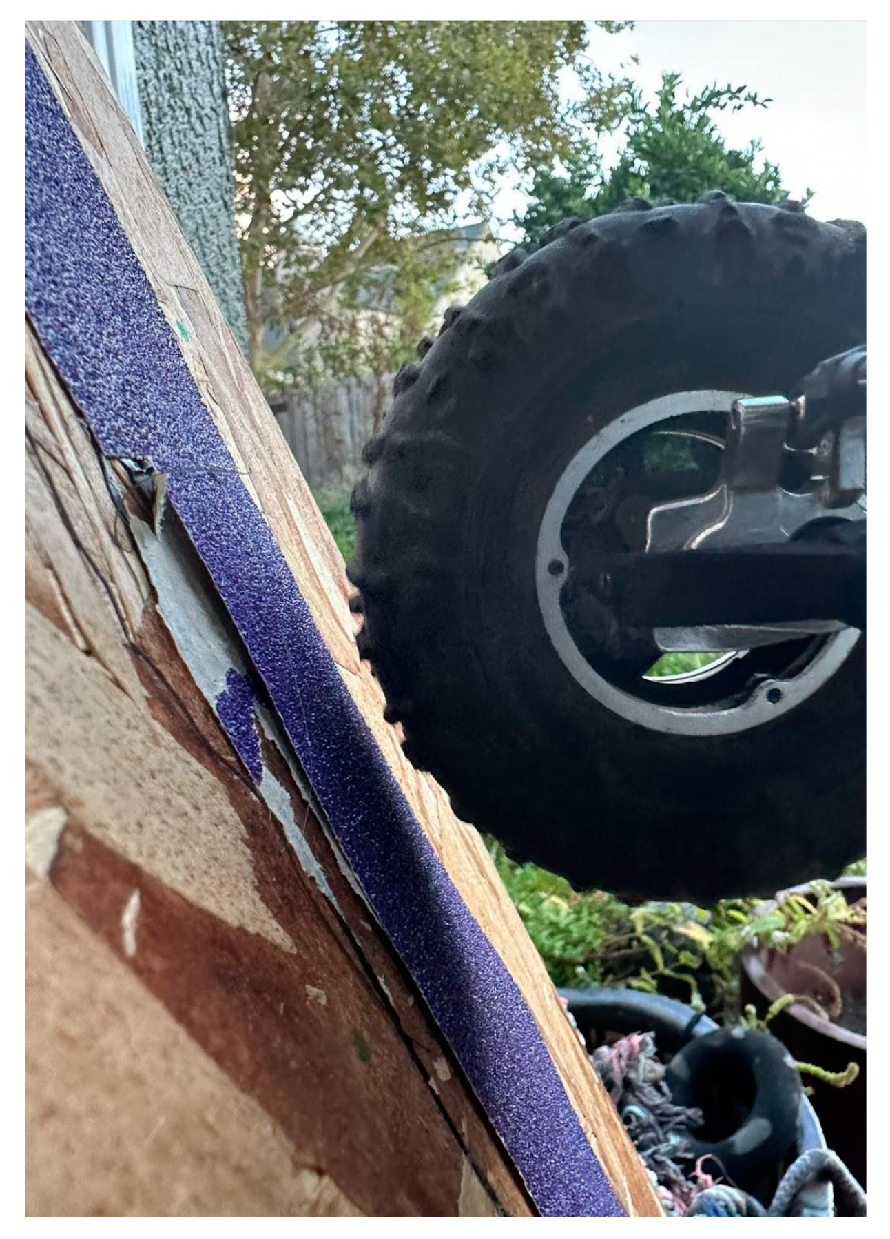
Figure 12.
outside view of front right wheel.
3.1.2. IRDSS-Equipped Crawler Analysis
The crawler equipped with the IRDSS demonstrated superior stability during the ascent.It successfully achieved a maximum climbing angle of 64.8° before the onset of instability was observed, and the improvement is beyond the error bars . As shown in Figure 6 and Figure 7, at this angle, the crawler remained close to the tipping point but did not experience any wheel lift or roll-over. Which can prove that the torque twist effet has been mostly canceled by introducing IRDSS.
Figure 13.
Inside view of the front right wheel.
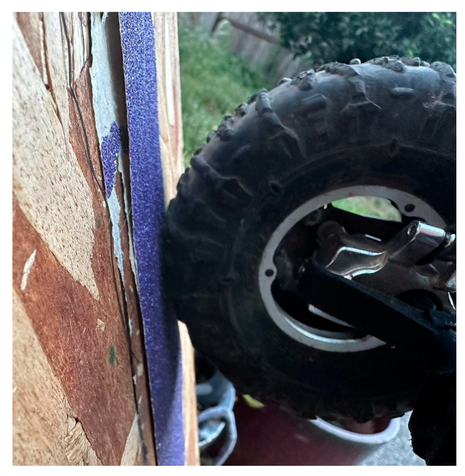
Figure 14.
Outside view of the front right wheel.
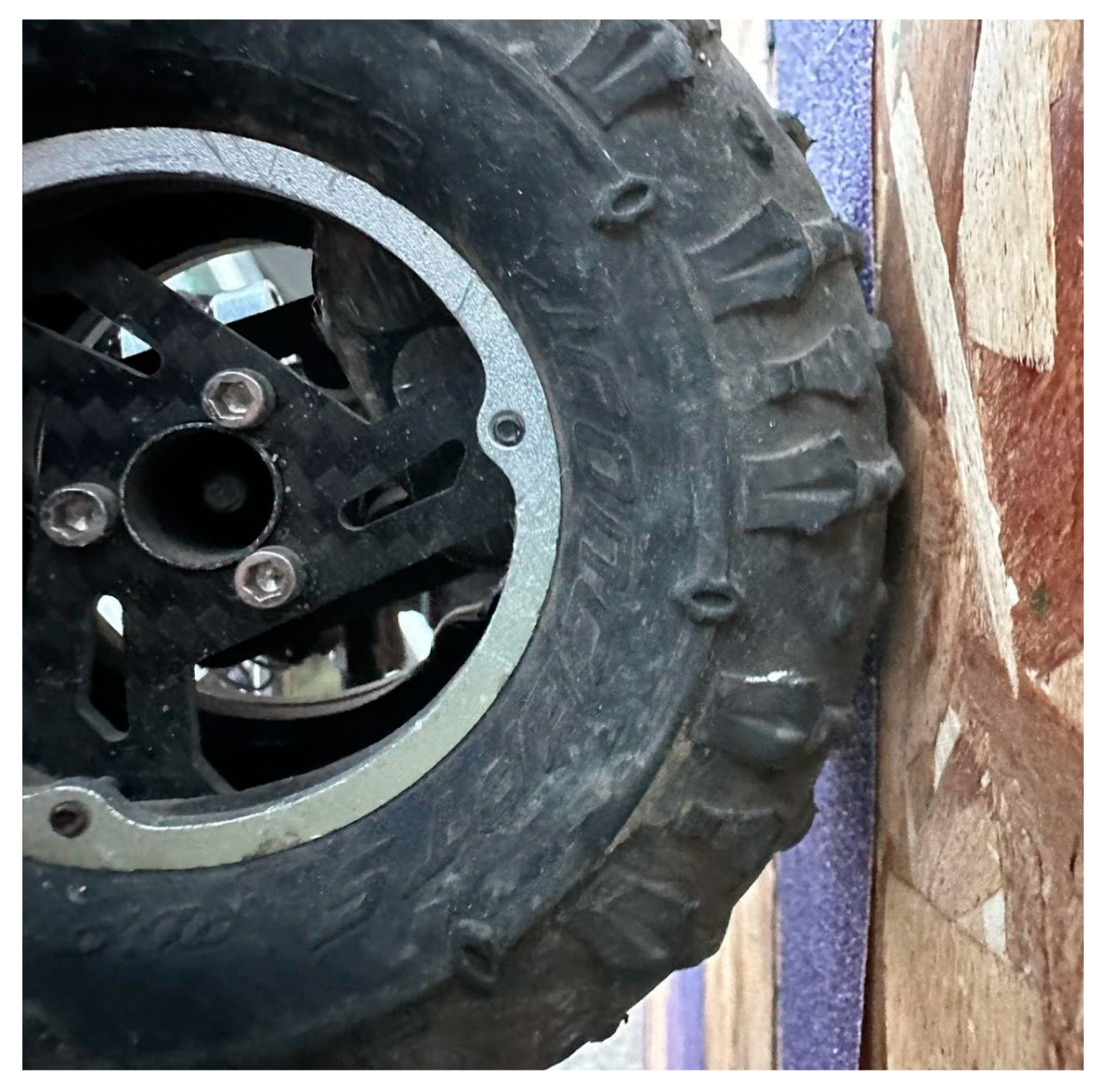
The IRDSS effectively counteracted the torque-induced instability, allowing for a steeper climb.
3.1.3. General Analysis
In testing the coastal rock surface simulation, the IRDSS provided a clear advantage in maintaining stability on steep, uneven surfaces, allowing the crawler to climb at angles that would cause a standard crawler to lose traction and tip over.
3.2. Test on Simulated Clay Surface
The clay surface will be simulated by using 220-grit sandpaper, representing a lower-friction environment typical of clay or loose dirt terrains. The test aimed to measure the maximum climb angle before traction was lost, comparing the grip capabilities of both crawlers under these conditions. The testing results of IRDSS-Equipped Crawler and Standard Crawler on the 220-grit sandpaper are shown in Table 3.
According to Table 3, both crawlers experienced a loss of traction at an angle of approximately 48°. Due to the extra weight from the IRDSS system, the crawler’s climbing angle is less than 2% smaller than that of the regular system. Neither crawler could maintain grip beyond this point, resulting in a failure to climb any further.
The lack of traction was the primary limiting factor, rather than torque-induced roll-over. The IRDSS did not significantly impact the crawler’s performance on this surface, as the limiting factor was the grip between the tires and the clay-like surface, rather than the crawler’s balance or torque management.
3.3. Summary of Findings
The IRDSS improved stability on steep, rocky surfaces, allowing for higher climb angles before instability occurred. However, on low-friction surfaces like simulated clay, both crawlers were similarly limited by traction, and the IRDSS offered no significant advantage. These results highlight that terrain type plays a critical role in the benefits of the IRDSS. For rocky terrains, the IRDSS significantly boosts performance, but on softer, low-traction surfaces, other modifications may be more useful.
4. Analysis of Discrepancies Between Theoretical and Real-World Climbing Angles
The previous results are shown in the following graphs
Figure 15.
The result of average climbing angle for regular and IRDSS crawlers on different Surfaces.
Figure 15.
The result of average climbing angle for regular and IRDSS crawlers on different Surfaces.
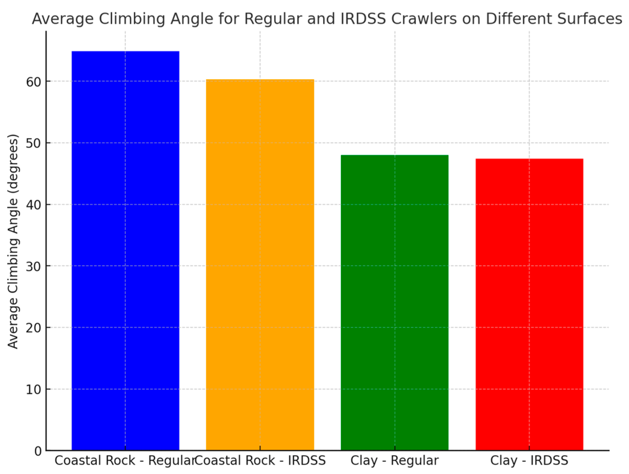
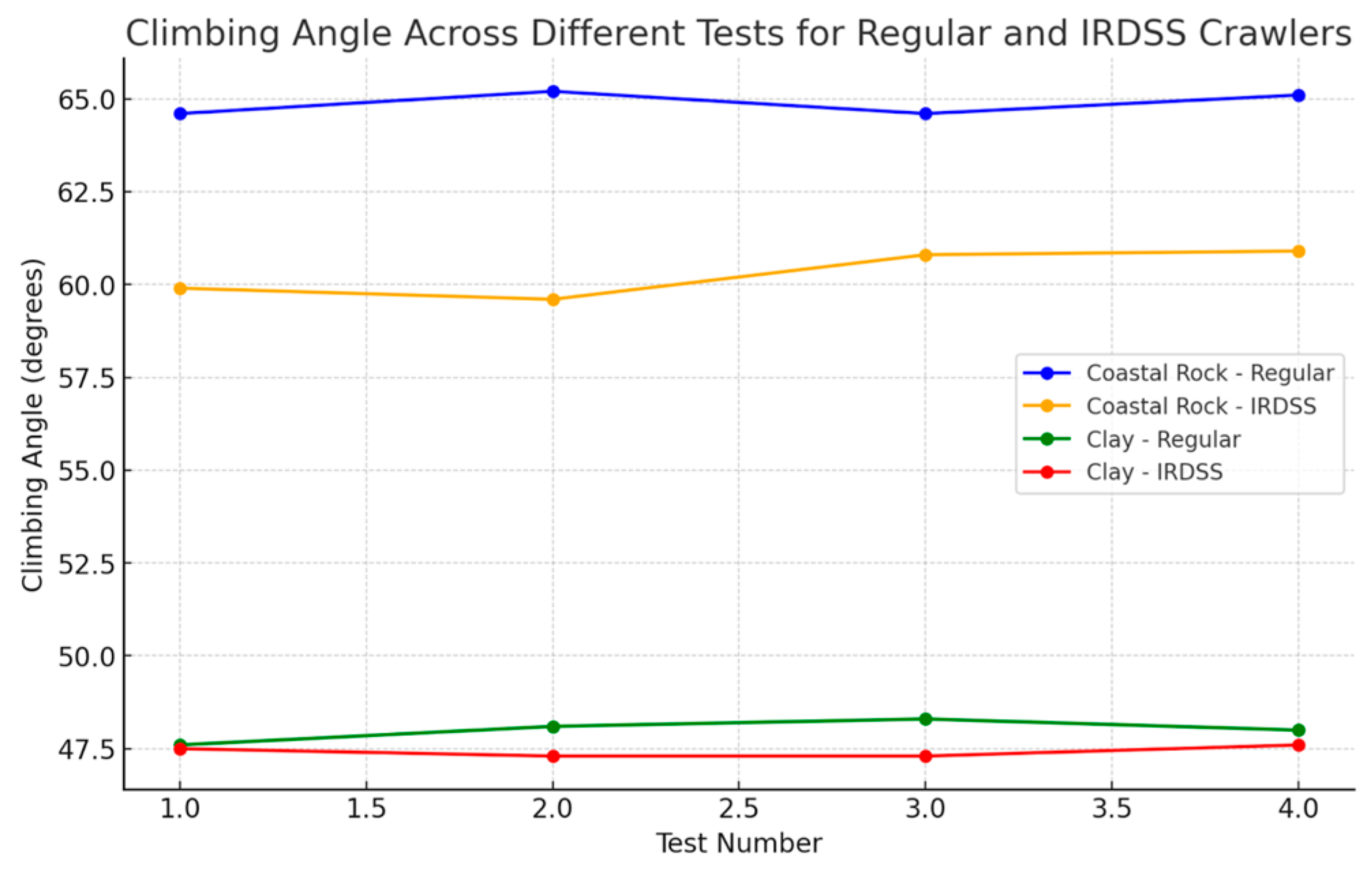
Figure 16.
The result of climbing angle across different tests for regular and IRDSS crawlers.
Possible Error Analysis
The maximum climbing angles observed in real-world tests were lower than the theoretical predictions due to several factors. The first and the most possible error might be caused by theoretical models assuming ideal traction, but real-world factors such as tire wear, tread pattern, and surface irregularities reduce grip, lowering the effective climb angle. Even minor debris on the surface can affect performance. Also, the dynamic load shifts during climbing alter weight distribution, temporarily reducing traction and causing the crawler to lose grip. Additionally, suspension and chassis flex under load can result in uneven weight distribution, affecting traction. Moreover, temperature and humidity impact both tire pliability and surface grip. Cooler temperatures may reduce the tires’ ability to conform to the surface, and humidity may lower friction if moisture accumulates, further decreasing traction. Furthermore, idealized assumptions in theoretical models—like uniform tire pressure and consistent friction—do not fully capture the complexity of real-world conditions, leading to discrepancies between predicted and actual performance.
5. Conclusion
This study aimed to assess how the IRDSS and mass distribution adjustments could enhance RC crawler climbing performance on difficult terrains. The results showed that while the IRDSS improved performance on high-friction surfaces like rocky terrains, the actual climbing angles were lower than predicted due to real-world complexities.
Key findings include:
The IRDSS-equipped crawler performed better on simulated coastal rocks, achieving a higher climb angle than the standard crawler, but the actual angles were lower than theoretical predictions due to factors like tire traction, dynamic forces, and environmental conditions.The IRDSS’s benefits were most pronounced on rocky, high-friction surfaces, whereas on low-friction surfaces like clay, both the IRDSS and standard crawlers were equally limited by traction.Theoretical analysis is a valuable baseline for predicting performance, but real-world testing is essential to account for factors such as terrain-specific conditions, dynamic forces, and environmental influences.
References
- John. “What Is an RC Crawler?—RC Lobby.” Rc-Lobby.com, 2024, rc-lobby.com/what-is-an-rc-crawler. Accessed 26 Aug. 2024.
- “Discussion on RC Crawling.” RCCrawler, www.rccrawler.com/forum/showthread.php?t=631912. Accessed 30 Aug. 2024.
- “Flashback: AX10 Scorpion—Celebrating 10 Years of the RC Crawler Revolution.” Axial Adventure, www.axialadventure.com/axi-blog-flashback-ax10.html. Accessed 30 Sept. 2024.
- RSRC.biz. “Quick Tutorial: 10 Driveshafts Comparison for Your RC Car.” RSRC.biz, https://rsrc.biz/en/blog/quick-tutorial-10-driveshafts-comparaison-for-your-rc-car-n115. Accessed 29 Sep. 2024.
- “RC Crawler Weight Distribution Guide: How to Balance Your RC Crawler for Better Performance.” RC Tech Tips, rctechtips.com/rc-cars/rc-crawler-weight-distribution/. Accessed 30 Sep. 2024.
- Zeng. “关于陡坡攀爬状态下轴效应的一些探讨及解决方案.” Rcfans.com, 2018, app.rcfans.com/mag/circle/v1/forum/threadWapPage?tid=1048798&themecolor=f8980f&circle_id=117app.rcfans.com/mag/circle/v1/forum/threadWapPage?tid=1048798&themecolor=f8980f&circle_id=117. Accessed 26 Aug. 2024.
- Byerlee, Jim D. “Friction of Rocks.” U.S. Geological Survey, 1978, earthquake.usgs.gov/static/lfs/research/rockphysics/Friction_of_rocks.pdf. Accessed 30 Aug. 2024.
Figure 1.
Testing slope setup. The two sets of sandpaper tracks simulate different grips under the different surfaces of the run condition.
Figure 1.
Testing slope setup. The two sets of sandpaper tracks simulate different grips under the different surfaces of the run condition.
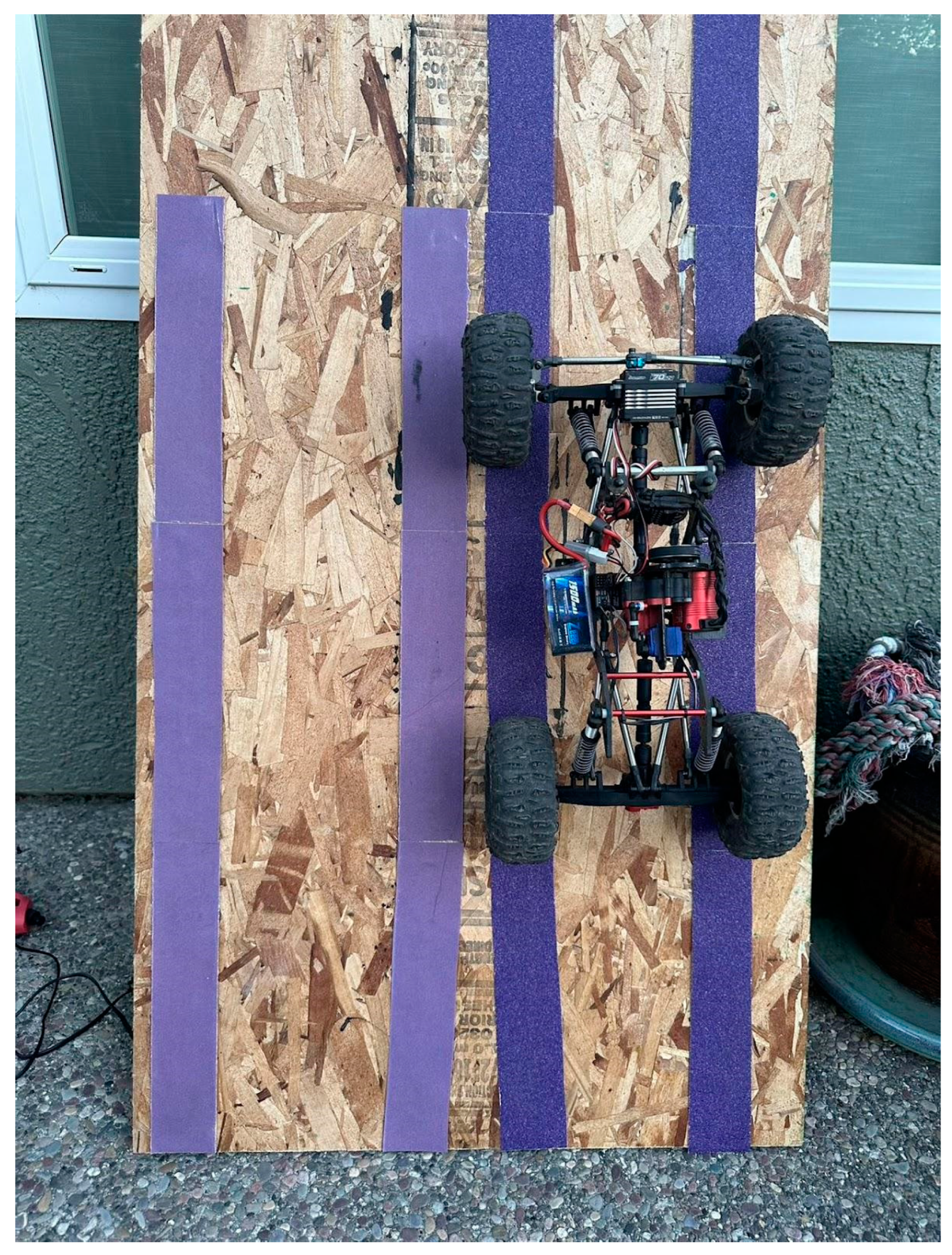

Table 1.
The IRDSS crawler will replace the regular transmission to the AX10 Transmission with IRDSS kit.
Table 1.
The IRDSS crawler will replace the regular transmission to the AX10 Transmission with IRDSS kit.
| Item ame | |
| Chassis | GrassHopper v3 |
| Transmission | AX10 Transmission |
| Axle | Meus Racing Plastic Nylon Portal Axles |
| Links | D1RC Stainless link set |
| Drive Shaft | D1RC Titanium Drive shaft |
| Rod ends | D1RC Rod End |
| Shocks | Icon 61-90mm Aluminum Shock |
| Power | Hobbywing Fusion SE 1800KV |
| Servo | AFRC-D3642HBM-S |
Table 2.
Climb angle results for both the IRDSS and regular crawler on the coastal rock surface simulation.
Table 2.
Climb angle results for both the IRDSS and regular crawler on the coastal rock surface simulation.
| Test 1 | Test 2 | Test 3 | Test 4 | |
| IRDSS | 64.6° | 65.2° | 64.6° | 65.1° |
| Regular | 59.9° | 59.6° | 60.8° | 60.9° |
Table 3.
Climb Angle Result For the Clay Surface Simulation.
| Test 1 | Test 2 | Test 3 | Test 4 | |
| Regular | 47.6° | 48.1° | 48.3° | 48.0° |
| IRDSS | 47.5° | 47.3° | 47.3° | 47.6° |
Disclaimer/Publisher’s Note: The statements, opinions and data contained in all publications are solely those of the individual author(s) and contributor(s) and not of MDPI and/or the editor(s). MDPI and/or the editor(s) disclaim responsibility for any injury to people or property resulting from any ideas, methods, instructions or products referred to in the content. |
© 2024 by the authors. Licensee MDPI, Basel, Switzerland. This article is an open access article distributed under the terms and conditions of the Creative Commons Attribution (CC BY) license (http://creativecommons.org/licenses/by/4.0/).
Copyright: This open access article is published under a Creative Commons CC BY 4.0 license, which permit the free download, distribution, and reuse, provided that the author and preprint are cited in any reuse.


