Methodology
To calculate the thrust power and torque for wall-mounted robots and quad-rotor drones, several methods can be applied to ensure accuracy and efficiency in robotic lifting systems. Below are the key methods used for these calculations:
1. Thrust Calculation for Quad-Rotor Drones
a) Basic Thrust Equation
To calculate the thrust required to lift a payload, the following basic formula can be used:
T is the thrust needed per rotor,
is the total mass of the drone plus the payload
g is the acceleration due to gravity
This calculation helps determine the baseline thrust each rotor needs to generate to counteract gravity.
b) Power Required for Hovering and Maneuvering
For drones, the power needed to maintain hover or perform maneuvers can be approximated using the formula:
P is the power required per rotor,
T is the thrust generated,
v is the velocity of the rotor's downward airflow.
This approach calculates the energy necessary to sustain hover, accounting for factors like rotor speed and air density.
Propeller Efficiency and Motor Sizing
To optimize thrust efficiency, it’s essential to account for propeller and motor characteristics. The following formula is helpful for determining the thrust coefficient
CT is the thrust coefficient based on propeller characteristics,
ρ is the air density
n is the rotor speed in revolutions per second,
D is the diameter of the propeller.
The thrust coefficient CT is typically obtained through testing or from manufacturer data and is crucial for selecting the appropriate motor and propeller configuration.
Control System Calculations (PID/LQ)
For drones that require stability in flight, control systems such as PID (Proportional-Integral-Derivative) and LQ (Linear Quadratic) techniques are used to adjust thrust dynamically. These control systems fine-tune rotor speeds in response to real-time changes in orientation and payload weight, maintaining stability and achieving precise maneuvers.
Torque Calculation for Wall-Mounted Robots
a) Torque Requirements for Vertical Motion
Wall-mounted robots require torque to lift and maneuver on vertical surfaces. Torque can be calculated using:
τ is the torque,
F is the force exerted by the motor to lift the payload,
r is the radius (distance from the axis of rotation to the point of force application).
The required force FFF is typically equal to the gravitational force acting on the payload, calculated as
Motor Sizing for Stability and Load Handling
The torque constant of the motor, often denoted as Kt is used to determine the appropriate motor size for the torque requirements. The torque provided by the motor can be calculated as:
τ is the torque,
Kt is the motor’s torque constant,
I is the current supplied to the motor.
Selecting the correct motor involves matching its torque constant with the load requirements, ensuring it can handle the desired payload without stalling or losing stability.
Control Algorithms for Vertical Navigation
For vertical wall-mounted systems, implementing control algorithms helps to counteract gravitational pull and manage load shifts. These algorithms adjust the torque output based on sensor feedback, ensuring the system remains stable on vertical surfaces. PID controllers are commonly used here as well, as they can dynamically adjust torque based on sensor input to maintain precise positioning.
Energy Efficiency and Optimization
a) Power Consumption Calculation
Power efficiency is critical in both systems. Power consumption in wall-mounted robots is calculated by:
P is the power consumed,
V is the voltage supplied to the motor,
I is the current drawn by the motor.
This helps to evaluate the energy requirements of each motor, ensuring that the design remains within the power limits of the system, which is especially important for battery-operated devices like drones.
Battery Sizing for Drones
Since drones rely on battery power, it’s essential to calculate the required battery capacity to sustain flight with the target payload. The battery capacity in milliamp-hours can be estimated based on total power requirements and desired flight time:
P is the power requirement in watts,
t is the desired time in hours,
V is the voltage in volts.
This calculation ensures that the drone can maintain sufficient flight time while carrying the specified payload, optimizing battery usage without sacrificing performance.
To calculate the requirements for a robot on a string driven by a stepper motor, we’ll consider the essential aspects: torque to lift the load, motor steps, and power consumption.
1. Determine Required Torque
For a robot suspended by a string, the motor must generate sufficient torque to lift its weight. The required torque τ depends on the gravitational force and the radius of the drum or pulley around which the string is wound.
Given parameters:
Mass of the robot (m) = e.g., 0.5 kg
Acceleration due to gravity (g) = 9.81 m/s²
Radius of the pulley (r) = e.g., 0.05 m
Torque Calculation:
The torque required τ to lift the robot can be calculated using:
Let’s substitute some values:
m=0.5kg
r=0.05m
This means the stepper motor must produce at least 0.245 Nm of torque to lift the robot.
2. Motor Steps for Desired Movement
To determine the required motor steps, we need to know the step angle of the motor and the circumference of the pulley.
If we want to lift the robot by a certain distance ddd, we can calculate the number of pulley rotations needed and, subsequently, the required motor steps.
Steps Calculation:
For a given
step angle θ of the motor (e.g., 1.8° per step, typical for many stepper motors), the
steps per revolution N can be found by:
If we need to lift the robot by, say, 0.1 m, the required number of steps is:
Power Consumption
The power required by the stepper motor depends on the voltage and current.
Power Calculation:
For a motor with a rated voltage V and current I, the power P consumed is:
For instance, if the motor operates at 12 V and 1.5 A:
Summary of Calculations:
Torque required: 0.245 Nm
Steps for 0.1 m lift: ~64 steps (for a motor with 1.8° step angle)
Power consumption: 18 W (for a 12 V, 1.5 A motor)
These calculations will help you determine if a specific stepper motor can effectively lift the robot along the string and estimate the power needed. Let me know if you’d like any adjustments or additional details!
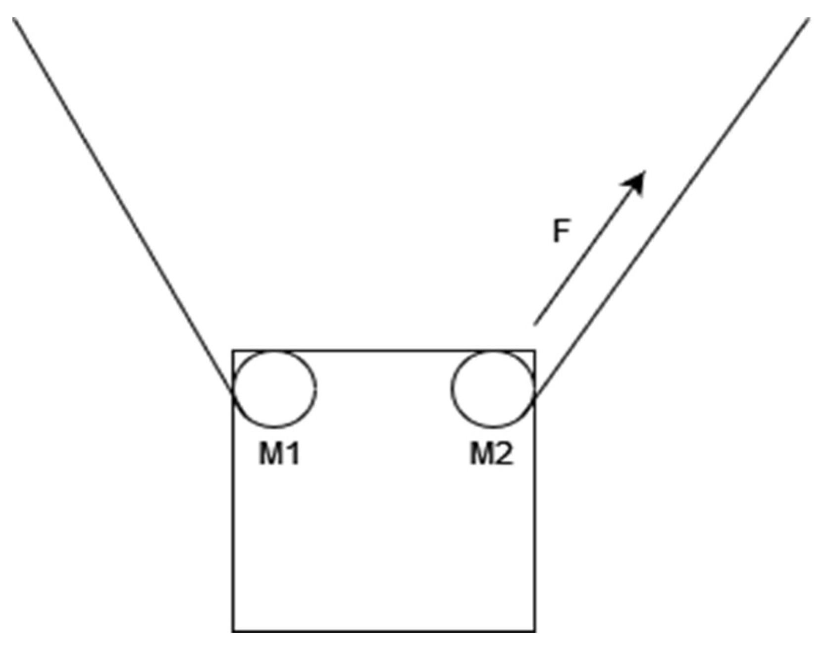
Figure 1.
Wall Mounted Robot Used for Vector Outline Drawing.
Figure 1.
Wall Mounted Robot Used for Vector Outline Drawing.
Table 1.
Table of a System.
Table 1.
Table of a System.
| Weight (g) |
Weight (KG) |
Torque (NM) |
Power (W) |
Voltage (V) |
Current (A) |
| 200 |
0.2 |
0.2×9.81×0.05=0.098 |
≈2.4 |
12 |
0.2 |
| 300 |
0.3 |
0.3×9.81×0.05=0.147 |
≈3.6 |
12 |
0.3 |
| 400 |
0.4 |
0.4×9.81×0.05=0.196 |
≈4.8 |
12 |
0.4 |
| 500 |
0.5 |
0.5×9.81×0.05=0.245 |
≈6.0 |
12 |
0.5 |
Discussion
The calculations and results presented in this study offer valuable insights into the specific power, torque, and motor requirements for a robotic system designed to lift weights along a vertical path using a stepper motor. By examining weights ranging from 200g to 500g, this analysis provides a framework for understanding the limitations and optimizations needed for robotic lifting applications.
Torque Requirements and Stability
The torque requirements for lifting weights of varying masses highlight the impact of load weight on motor performance. As demonstrated, a higher payload requires greater torque to overcome gravitational forces and achieve a stable lift. The torque values calculated (0.098 Nm to 0.245 Nm) reflect the increasing demands placed on the motor as the weight increases. For real-world applications, this insight emphasizes the importance of selecting a motor with sufficient torque capacity to handle peak load requirements without sacrificing stability. In cases where precise vertical movement is critical—such as inspection robots on vertical surfaces—this analysis underscores the need for motors capable of generating reliable torque across different load scenarios.
Power Consumption and Efficiency
The power consumption values obtained (ranging from 2.4 W to 6.0 W) suggest that the system remains within manageable power requirements even as the payload increases. However, as weight increases, so does the demand on both the motor and power supply. This result indicates a trade-off between load capacity and energy efficiency. For applications where battery life or energy usage is a constraint—such as in drones or mobile robots—optimizing the weight of the payload becomes essential to maintaining efficiency. Power efficiency can be further optimized by selecting motors that match the specific torque and power requirements, potentially reducing the current draw and extending operational time.
Voltage and Current Implications
The voltage and current requirements provide a practical guide for powering the robotic system. The consistent use of 12V across different weights simplifies the power supply setup, making it feasible to use a single, standardized voltage source. The increasing current requirements (from 0.2A for 200g to 0.5A for 500g) indicate the need for a power source capable of supplying variable current to match the lifting demands. This is particularly important in systems where weight might vary dynamically, necessitating a flexible power supply that can adapt to different load scenarios without risking motor burnout or power insufficiency.
Implications for Robotic Design
These findings have several implications for the design of robotic lifting systems:
Motor Selection and Sizing: Selecting a motor with an appropriate torque constant is essential to ensure the robot can lift the maximum expected payload while maintaining control and stability. Motors with higher torque constants may be more suitable for heavy-lift applications, while motors optimized for efficiency may be preferable for lighter tasks where energy conservation is a priority.
Energy Management: The relationship between payload weight and power consumption suggests that energy management strategies should be incorporated into the design. For example, lighter materials or optimized load distribution can help reduce power draw, thereby enhancing battery life in mobile applications. Additionally, incorporating regenerative braking or energy recovery mechanisms could further improve efficiency in systems with frequent lift-and-release cycles.
Control Systems: Implementing control systems such as PID or LQ controllers can improve precision in torque and power application, especially for variable loads. By dynamically adjusting motor power based on real-time load feedback, control systems can optimize the lifting process, maintaining stability and reducing unnecessary power expenditure.
Application-Specific Considerations: Different applications may have distinct requirements based on the operating environment and system constraints. For instance, wall-mounted robots used for vertical inspections require high torque and stability for safe operation, while drones used in aerial lifting prioritize weight and power efficiency to maximize flight time. Understanding the unique needs of each application allows for the customization of motor parameters to meet specific operational goals.